WO2017047109A1 - Dispositif de commande de purification d'échappement - Google Patents
Dispositif de commande de purification d'échappement Download PDFInfo
- Publication number
- WO2017047109A1 WO2017047109A1 PCT/JP2016/053031 JP2016053031W WO2017047109A1 WO 2017047109 A1 WO2017047109 A1 WO 2017047109A1 JP 2016053031 W JP2016053031 W JP 2016053031W WO 2017047109 A1 WO2017047109 A1 WO 2017047109A1
- Authority
- WO
- WIPO (PCT)
- Prior art keywords
- catalyst
- oxygen storage
- storage capacity
- fuel cut
- time
- Prior art date
Links
Images

Classifications
-
- F—MECHANICAL ENGINEERING; LIGHTING; HEATING; WEAPONS; BLASTING
- F02—COMBUSTION ENGINES; HOT-GAS OR COMBUSTION-PRODUCT ENGINE PLANTS
- F02D—CONTROLLING COMBUSTION ENGINES
- F02D41/00—Electrical control of supply of combustible mixture or its constituents
- F02D41/02—Circuit arrangements for generating control signals
- F02D41/04—Introducing corrections for particular operating conditions
- F02D41/12—Introducing corrections for particular operating conditions for deceleration
- F02D41/123—Introducing corrections for particular operating conditions for deceleration the fuel injection being cut-off
-
- F—MECHANICAL ENGINEERING; LIGHTING; HEATING; WEAPONS; BLASTING
- F01—MACHINES OR ENGINES IN GENERAL; ENGINE PLANTS IN GENERAL; STEAM ENGINES
- F01N—GAS-FLOW SILENCERS OR EXHAUST APPARATUS FOR MACHINES OR ENGINES IN GENERAL; GAS-FLOW SILENCERS OR EXHAUST APPARATUS FOR INTERNAL COMBUSTION ENGINES
- F01N11/00—Monitoring or diagnostic devices for exhaust-gas treatment apparatus, e.g. for catalytic activity
- F01N11/002—Monitoring or diagnostic devices for exhaust-gas treatment apparatus, e.g. for catalytic activity the diagnostic devices measuring or estimating temperature or pressure in, or downstream of the exhaust apparatus
-
- F—MECHANICAL ENGINEERING; LIGHTING; HEATING; WEAPONS; BLASTING
- F01—MACHINES OR ENGINES IN GENERAL; ENGINE PLANTS IN GENERAL; STEAM ENGINES
- F01N—GAS-FLOW SILENCERS OR EXHAUST APPARATUS FOR MACHINES OR ENGINES IN GENERAL; GAS-FLOW SILENCERS OR EXHAUST APPARATUS FOR INTERNAL COMBUSTION ENGINES
- F01N11/00—Monitoring or diagnostic devices for exhaust-gas treatment apparatus, e.g. for catalytic activity
- F01N11/007—Monitoring or diagnostic devices for exhaust-gas treatment apparatus, e.g. for catalytic activity the diagnostic devices measuring oxygen or air concentration downstream of the exhaust apparatus
-
- F—MECHANICAL ENGINEERING; LIGHTING; HEATING; WEAPONS; BLASTING
- F01—MACHINES OR ENGINES IN GENERAL; ENGINE PLANTS IN GENERAL; STEAM ENGINES
- F01N—GAS-FLOW SILENCERS OR EXHAUST APPARATUS FOR MACHINES OR ENGINES IN GENERAL; GAS-FLOW SILENCERS OR EXHAUST APPARATUS FOR INTERNAL COMBUSTION ENGINES
- F01N13/00—Exhaust or silencing apparatus characterised by constructional features ; Exhaust or silencing apparatus, or parts thereof, having pertinent characteristics not provided for in, or of interest apart from, groups F01N1/00 - F01N5/00, F01N9/00, F01N11/00
- F01N13/009—Exhaust or silencing apparatus characterised by constructional features ; Exhaust or silencing apparatus, or parts thereof, having pertinent characteristics not provided for in, or of interest apart from, groups F01N1/00 - F01N5/00, F01N9/00, F01N11/00 having two or more separate purifying devices arranged in series
- F01N13/0093—Exhaust or silencing apparatus characterised by constructional features ; Exhaust or silencing apparatus, or parts thereof, having pertinent characteristics not provided for in, or of interest apart from, groups F01N1/00 - F01N5/00, F01N9/00, F01N11/00 having two or more separate purifying devices arranged in series the purifying devices are of the same type
-
- F—MECHANICAL ENGINEERING; LIGHTING; HEATING; WEAPONS; BLASTING
- F01—MACHINES OR ENGINES IN GENERAL; ENGINE PLANTS IN GENERAL; STEAM ENGINES
- F01N—GAS-FLOW SILENCERS OR EXHAUST APPARATUS FOR MACHINES OR ENGINES IN GENERAL; GAS-FLOW SILENCERS OR EXHAUST APPARATUS FOR INTERNAL COMBUSTION ENGINES
- F01N3/00—Exhaust or silencing apparatus having means for purifying, rendering innocuous, or otherwise treating exhaust
- F01N3/08—Exhaust or silencing apparatus having means for purifying, rendering innocuous, or otherwise treating exhaust for rendering innocuous
- F01N3/10—Exhaust or silencing apparatus having means for purifying, rendering innocuous, or otherwise treating exhaust for rendering innocuous by thermal or catalytic conversion of noxious components of exhaust
- F01N3/101—Three-way catalysts
-
- F—MECHANICAL ENGINEERING; LIGHTING; HEATING; WEAPONS; BLASTING
- F01—MACHINES OR ENGINES IN GENERAL; ENGINE PLANTS IN GENERAL; STEAM ENGINES
- F01N—GAS-FLOW SILENCERS OR EXHAUST APPARATUS FOR MACHINES OR ENGINES IN GENERAL; GAS-FLOW SILENCERS OR EXHAUST APPARATUS FOR INTERNAL COMBUSTION ENGINES
- F01N3/00—Exhaust or silencing apparatus having means for purifying, rendering innocuous, or otherwise treating exhaust
- F01N3/08—Exhaust or silencing apparatus having means for purifying, rendering innocuous, or otherwise treating exhaust for rendering innocuous
- F01N3/10—Exhaust or silencing apparatus having means for purifying, rendering innocuous, or otherwise treating exhaust for rendering innocuous by thermal or catalytic conversion of noxious components of exhaust
- F01N3/18—Exhaust or silencing apparatus having means for purifying, rendering innocuous, or otherwise treating exhaust for rendering innocuous by thermal or catalytic conversion of noxious components of exhaust characterised by methods of operation; Control
- F01N3/20—Exhaust or silencing apparatus having means for purifying, rendering innocuous, or otherwise treating exhaust for rendering innocuous by thermal or catalytic conversion of noxious components of exhaust characterised by methods of operation; Control specially adapted for catalytic conversion ; Methods of operation or control of catalytic converters
-
- F—MECHANICAL ENGINEERING; LIGHTING; HEATING; WEAPONS; BLASTING
- F01—MACHINES OR ENGINES IN GENERAL; ENGINE PLANTS IN GENERAL; STEAM ENGINES
- F01N—GAS-FLOW SILENCERS OR EXHAUST APPARATUS FOR MACHINES OR ENGINES IN GENERAL; GAS-FLOW SILENCERS OR EXHAUST APPARATUS FOR INTERNAL COMBUSTION ENGINES
- F01N3/00—Exhaust or silencing apparatus having means for purifying, rendering innocuous, or otherwise treating exhaust
- F01N3/08—Exhaust or silencing apparatus having means for purifying, rendering innocuous, or otherwise treating exhaust for rendering innocuous
- F01N3/10—Exhaust or silencing apparatus having means for purifying, rendering innocuous, or otherwise treating exhaust for rendering innocuous by thermal or catalytic conversion of noxious components of exhaust
- F01N3/24—Exhaust or silencing apparatus having means for purifying, rendering innocuous, or otherwise treating exhaust for rendering innocuous by thermal or catalytic conversion of noxious components of exhaust characterised by constructional aspects of converting apparatus
- F01N3/28—Construction of catalytic reactors
-
- F—MECHANICAL ENGINEERING; LIGHTING; HEATING; WEAPONS; BLASTING
- F01—MACHINES OR ENGINES IN GENERAL; ENGINE PLANTS IN GENERAL; STEAM ENGINES
- F01N—GAS-FLOW SILENCERS OR EXHAUST APPARATUS FOR MACHINES OR ENGINES IN GENERAL; GAS-FLOW SILENCERS OR EXHAUST APPARATUS FOR INTERNAL COMBUSTION ENGINES
- F01N9/00—Electrical control of exhaust gas treating apparatus
-
- F—MECHANICAL ENGINEERING; LIGHTING; HEATING; WEAPONS; BLASTING
- F02—COMBUSTION ENGINES; HOT-GAS OR COMBUSTION-PRODUCT ENGINE PLANTS
- F02D—CONTROLLING COMBUSTION ENGINES
- F02D41/00—Electrical control of supply of combustible mixture or its constituents
- F02D41/02—Circuit arrangements for generating control signals
- F02D41/021—Introducing corrections for particular conditions exterior to the engine
- F02D41/0235—Introducing corrections for particular conditions exterior to the engine in relation with the state of the exhaust gas treating apparatus
- F02D41/0295—Control according to the amount of oxygen that is stored on the exhaust gas treating apparatus
-
- F—MECHANICAL ENGINEERING; LIGHTING; HEATING; WEAPONS; BLASTING
- F02—COMBUSTION ENGINES; HOT-GAS OR COMBUSTION-PRODUCT ENGINE PLANTS
- F02D—CONTROLLING COMBUSTION ENGINES
- F02D41/00—Electrical control of supply of combustible mixture or its constituents
- F02D41/02—Circuit arrangements for generating control signals
- F02D41/04—Introducing corrections for particular operating conditions
- F02D41/12—Introducing corrections for particular operating conditions for deceleration
-
- F—MECHANICAL ENGINEERING; LIGHTING; HEATING; WEAPONS; BLASTING
- F02—COMBUSTION ENGINES; HOT-GAS OR COMBUSTION-PRODUCT ENGINE PLANTS
- F02D—CONTROLLING COMBUSTION ENGINES
- F02D41/00—Electrical control of supply of combustible mixture or its constituents
- F02D41/02—Circuit arrangements for generating control signals
- F02D41/14—Introducing closed-loop corrections
- F02D41/1438—Introducing closed-loop corrections using means for determining characteristics of the combustion gases; Sensors therefor
- F02D41/1439—Introducing closed-loop corrections using means for determining characteristics of the combustion gases; Sensors therefor characterised by the position of the sensor
- F02D41/1441—Plural sensors
-
- F—MECHANICAL ENGINEERING; LIGHTING; HEATING; WEAPONS; BLASTING
- F02—COMBUSTION ENGINES; HOT-GAS OR COMBUSTION-PRODUCT ENGINE PLANTS
- F02D—CONTROLLING COMBUSTION ENGINES
- F02D41/00—Electrical control of supply of combustible mixture or its constituents
- F02D41/02—Circuit arrangements for generating control signals
- F02D41/14—Introducing closed-loop corrections
- F02D41/1438—Introducing closed-loop corrections using means for determining characteristics of the combustion gases; Sensors therefor
- F02D41/1444—Introducing closed-loop corrections using means for determining characteristics of the combustion gases; Sensors therefor characterised by the characteristics of the combustion gases
- F02D41/1454—Introducing closed-loop corrections using means for determining characteristics of the combustion gases; Sensors therefor characterised by the characteristics of the combustion gases the characteristics being an oxygen content or concentration or the air-fuel ratio
-
- F—MECHANICAL ENGINEERING; LIGHTING; HEATING; WEAPONS; BLASTING
- F01—MACHINES OR ENGINES IN GENERAL; ENGINE PLANTS IN GENERAL; STEAM ENGINES
- F01N—GAS-FLOW SILENCERS OR EXHAUST APPARATUS FOR MACHINES OR ENGINES IN GENERAL; GAS-FLOW SILENCERS OR EXHAUST APPARATUS FOR INTERNAL COMBUSTION ENGINES
- F01N2550/00—Monitoring or diagnosing the deterioration of exhaust systems
- F01N2550/02—Catalytic activity of catalytic converters
-
- F—MECHANICAL ENGINEERING; LIGHTING; HEATING; WEAPONS; BLASTING
- F01—MACHINES OR ENGINES IN GENERAL; ENGINE PLANTS IN GENERAL; STEAM ENGINES
- F01N—GAS-FLOW SILENCERS OR EXHAUST APPARATUS FOR MACHINES OR ENGINES IN GENERAL; GAS-FLOW SILENCERS OR EXHAUST APPARATUS FOR INTERNAL COMBUSTION ENGINES
- F01N2560/00—Exhaust systems with means for detecting or measuring exhaust gas components or characteristics
- F01N2560/02—Exhaust systems with means for detecting or measuring exhaust gas components or characteristics the means being an exhaust gas sensor
- F01N2560/025—Exhaust systems with means for detecting or measuring exhaust gas components or characteristics the means being an exhaust gas sensor for measuring or detecting O2, e.g. lambda sensors
-
- F—MECHANICAL ENGINEERING; LIGHTING; HEATING; WEAPONS; BLASTING
- F01—MACHINES OR ENGINES IN GENERAL; ENGINE PLANTS IN GENERAL; STEAM ENGINES
- F01N—GAS-FLOW SILENCERS OR EXHAUST APPARATUS FOR MACHINES OR ENGINES IN GENERAL; GAS-FLOW SILENCERS OR EXHAUST APPARATUS FOR INTERNAL COMBUSTION ENGINES
- F01N2570/00—Exhaust treating apparatus eliminating, absorbing or adsorbing specific elements or compounds
- F01N2570/16—Oxygen
-
- F—MECHANICAL ENGINEERING; LIGHTING; HEATING; WEAPONS; BLASTING
- F01—MACHINES OR ENGINES IN GENERAL; ENGINE PLANTS IN GENERAL; STEAM ENGINES
- F01N—GAS-FLOW SILENCERS OR EXHAUST APPARATUS FOR MACHINES OR ENGINES IN GENERAL; GAS-FLOW SILENCERS OR EXHAUST APPARATUS FOR INTERNAL COMBUSTION ENGINES
- F01N2900/00—Details of electrical control or of the monitoring of the exhaust gas treating apparatus
- F01N2900/06—Parameters used for exhaust control or diagnosing
- F01N2900/08—Parameters used for exhaust control or diagnosing said parameters being related to the engine
-
- F—MECHANICAL ENGINEERING; LIGHTING; HEATING; WEAPONS; BLASTING
- F01—MACHINES OR ENGINES IN GENERAL; ENGINE PLANTS IN GENERAL; STEAM ENGINES
- F01N—GAS-FLOW SILENCERS OR EXHAUST APPARATUS FOR MACHINES OR ENGINES IN GENERAL; GAS-FLOW SILENCERS OR EXHAUST APPARATUS FOR INTERNAL COMBUSTION ENGINES
- F01N2900/00—Details of electrical control or of the monitoring of the exhaust gas treating apparatus
- F01N2900/06—Parameters used for exhaust control or diagnosing
- F01N2900/16—Parameters used for exhaust control or diagnosing said parameters being related to the exhaust apparatus, e.g. particulate filter or catalyst
- F01N2900/1602—Temperature of exhaust gas apparatus
-
- F—MECHANICAL ENGINEERING; LIGHTING; HEATING; WEAPONS; BLASTING
- F01—MACHINES OR ENGINES IN GENERAL; ENGINE PLANTS IN GENERAL; STEAM ENGINES
- F01N—GAS-FLOW SILENCERS OR EXHAUST APPARATUS FOR MACHINES OR ENGINES IN GENERAL; GAS-FLOW SILENCERS OR EXHAUST APPARATUS FOR INTERNAL COMBUSTION ENGINES
- F01N2900/00—Details of electrical control or of the monitoring of the exhaust gas treating apparatus
- F01N2900/06—Parameters used for exhaust control or diagnosing
- F01N2900/16—Parameters used for exhaust control or diagnosing said parameters being related to the exhaust apparatus, e.g. particulate filter or catalyst
- F01N2900/1621—Catalyst conversion efficiency
-
- F—MECHANICAL ENGINEERING; LIGHTING; HEATING; WEAPONS; BLASTING
- F01—MACHINES OR ENGINES IN GENERAL; ENGINE PLANTS IN GENERAL; STEAM ENGINES
- F01N—GAS-FLOW SILENCERS OR EXHAUST APPARATUS FOR MACHINES OR ENGINES IN GENERAL; GAS-FLOW SILENCERS OR EXHAUST APPARATUS FOR INTERNAL COMBUSTION ENGINES
- F01N2900/00—Details of electrical control or of the monitoring of the exhaust gas treating apparatus
- F01N2900/06—Parameters used for exhaust control or diagnosing
- F01N2900/16—Parameters used for exhaust control or diagnosing said parameters being related to the exhaust apparatus, e.g. particulate filter or catalyst
- F01N2900/1624—Catalyst oxygen storage capacity
-
- F—MECHANICAL ENGINEERING; LIGHTING; HEATING; WEAPONS; BLASTING
- F02—COMBUSTION ENGINES; HOT-GAS OR COMBUSTION-PRODUCT ENGINE PLANTS
- F02D—CONTROLLING COMBUSTION ENGINES
- F02D41/00—Electrical control of supply of combustible mixture or its constituents
- F02D41/02—Circuit arrangements for generating control signals
- F02D41/14—Introducing closed-loop corrections
- F02D41/1401—Introducing closed-loop corrections characterised by the control or regulation method
- F02D2041/1413—Controller structures or design
- F02D2041/1431—Controller structures or design the system including an input-output delay
-
- F—MECHANICAL ENGINEERING; LIGHTING; HEATING; WEAPONS; BLASTING
- F02—COMBUSTION ENGINES; HOT-GAS OR COMBUSTION-PRODUCT ENGINE PLANTS
- F02D—CONTROLLING COMBUSTION ENGINES
- F02D2200/00—Input parameters for engine control
- F02D2200/02—Input parameters for engine control the parameters being related to the engine
- F02D2200/08—Exhaust gas treatment apparatus parameters
- F02D2200/0802—Temperature of the exhaust gas treatment apparatus
-
- Y—GENERAL TAGGING OF NEW TECHNOLOGICAL DEVELOPMENTS; GENERAL TAGGING OF CROSS-SECTIONAL TECHNOLOGIES SPANNING OVER SEVERAL SECTIONS OF THE IPC; TECHNICAL SUBJECTS COVERED BY FORMER USPC CROSS-REFERENCE ART COLLECTIONS [XRACs] AND DIGESTS
- Y02—TECHNOLOGIES OR APPLICATIONS FOR MITIGATION OR ADAPTATION AGAINST CLIMATE CHANGE
- Y02T—CLIMATE CHANGE MITIGATION TECHNOLOGIES RELATED TO TRANSPORTATION
- Y02T10/00—Road transport of goods or passengers
- Y02T10/10—Internal combustion engine [ICE] based vehicles
- Y02T10/12—Improving ICE efficiencies
-
- Y—GENERAL TAGGING OF NEW TECHNOLOGICAL DEVELOPMENTS; GENERAL TAGGING OF CROSS-SECTIONAL TECHNOLOGIES SPANNING OVER SEVERAL SECTIONS OF THE IPC; TECHNICAL SUBJECTS COVERED BY FORMER USPC CROSS-REFERENCE ART COLLECTIONS [XRACs] AND DIGESTS
- Y02—TECHNOLOGIES OR APPLICATIONS FOR MITIGATION OR ADAPTATION AGAINST CLIMATE CHANGE
- Y02T—CLIMATE CHANGE MITIGATION TECHNOLOGIES RELATED TO TRANSPORTATION
- Y02T10/00—Road transport of goods or passengers
- Y02T10/10—Internal combustion engine [ICE] based vehicles
- Y02T10/40—Engine management systems
Definitions
- the present invention relates to a vehicle exhaust gas purification control apparatus in which a catalyst containing an oxygen storage material is interposed in an engine exhaust system.
- a three-way catalyst containing an oxygen storage material is known as one of the catalysts interposed in the exhaust system of a gasoline vehicle.
- a three-way catalyst is a catalyst that simultaneously promotes a reduction reaction of nitrogen oxides (NOx), an oxidation reaction of hydrocarbons (HnCm), and an oxidation reaction of carbon monoxide (CO) in an atmosphere near the theoretical air-fuel ratio.
- the oxygen storage material is a promoter having a characteristic of storing oxygen in a lean atmosphere and desorbing the stored oxygen during a lean operation in a rich atmosphere.
- oxygen storage materials include ceria (CeO 2 ), ceria-zirconia composite material (CeO 2 -ZrO 2 ), alumina-ceria-zirconia composite material (Al 2 O 3 -CeO 2 -ZrO 2 ), these Examples include a material in which the second and third element components are combined with the material.
- these oxygen storage materials include a material in which the second and third element components are combined with the material.
- a control called fuel cut may be performed on an engine equipped with the above catalyst in an exhaust system.
- the fuel cut is a control for temporarily stopping the fuel supply to the engine when a predetermined fuel cut condition is satisfied.
- This control is performed, for example, during inertia running or deceleration of the vehicle, and functions to suppress wasteful fuel consumption. That is, the fuel consumption of the vehicle can be improved by performing the fuel cut.
- the amount of oxygen stored in the oxygen storage material of the catalyst may become excessive.
- Such excessive stored oxygen can reduce the exhaust purification performance when returning from the fuel cut. That is, when the engine returns from the fuel cut, the amount of oxygen desorbed from the oxygen storage material temporarily increases, so the air-fuel ratio becomes slightly leaner and the nitrogen oxide purification rate tends to decrease.
- the fuel injection amount in order to set the air-fuel ratio around the catalyst to the stoichiometric air-fuel ratio in consideration of the amount of desorbed oxygen, the fuel injection amount must be increased. As a result, the total fuel injection amount increases, and the fuel efficiency improvement effect due to the fuel cut can be offset.
- One of the objects of the present invention was created in view of the above-described problems, and provides an exhaust purification control device that can improve fuel efficiency while suppressing a decrease in exhaust purification performance of a catalyst. is there. It should be noted that the present invention is not limited to this purpose, and is an operational effect that is derived from each configuration shown in “Mode for Carrying Out the Invention” to be described later. Can be positioned as a purpose.
- the exhaust purification control device disclosed herein includes a fuel cut control unit that shuts off fuel supply to the engine after a predetermined delay time has elapsed when a predetermined fuel cut condition is satisfied. Further, a calculation unit is provided for calculating an oxygen storage capacity (for example, an index value representing the oxygen storage capacity) of the catalyst including the oxygen storage material interposed in the exhaust system of the engine. Furthermore, a setting unit is provided for setting the length of the delay time according to the oxygen storage capacity calculated by the calculation unit.
- the oxygen storage capacity preferably represents the weight of oxygen stored in the catalyst. For example, it is preferable that the oxygen storage capacity is the highest when the catalyst is new, and that the oxygen storage capacity decreases as the catalyst is used for a long time.
- the setting unit shortens the delay time as the oxygen storage capacity is lower.
- the delay time when the catalyst is new is set to be the longest, and the delay time is set to be shorter as the catalyst is used longer.
- the calculation unit determines that the oxygen storage capacity is lower as the output inversion time from the response time of the upstream sensor to the response time of the downstream sensor with respect to a change in the air-fuel ratio is shorter.
- the catalyst has a front catalyst located upstream of the exhaust system and a rear catalyst located downstream. Moreover, it is preferable to provide an intermediate sensor for detecting an oxygen concentration between the front catalyst and the rear catalyst. In this case, it is preferable that the calculation unit determines that the oxygen storage capacity is lower as the second output inversion time from the response time of the upstream sensor to the response time of the intermediate sensor with respect to the change in air-fuel ratio is shorter. . (5) It is preferable that the calculation unit calculates the oxygen storage capacity in the previous period based on the degree of aging of the catalyst. For example, the oxygen storage capacity in the previous period may be calculated based on the usage time of the catalyst (accumulated value obtained by accumulating the usage time from when the catalyst is new).
- the calculation unit calculates the oxygen storage capacity when a condition that the operation state of the engine is stable for a predetermined period is satisfied. In other words, “the operating state of the engine is stable for a predetermined period” is preferably included in the condition for calculating the oxygen storage capacity. (7) It is preferable that the calculation unit calculates the oxygen storage capacity when a condition that the temperature of the catalyst is within a predetermined temperature range is satisfied. In other words, “the temperature of the catalyst is within a predetermined temperature range” is preferably included in the condition for calculating the oxygen storage capacity.
- the amount of oxygen stored in the catalyst can be adjusted, and the deterioration of the exhaust purification performance of the catalyst can be suppressed.
- the occlusion of oxygen it is possible to suppress the enrichment of the combustion air-fuel ratio of the engine that is performed after returning from the fuel cut, and it is possible to improve fuel efficiency.
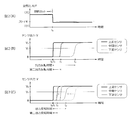
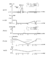
- FIG. 2A is a graph for explaining a method for calculating the oxygen storage capacity of a catalyst
- FIG. 2A is the air-fuel ratio change at the time of fuel cut return
- FIGS. 2B and 2C are output characteristics of the oxygen concentration sensor. Represents. It is a graph which shows the relationship between the oxygen storage capacity of a catalyst, and the delay time of a fuel cut. It is a flowchart which illustrates the control procedure of a fuel cut. It is a flowchart which illustrates the setting procedure of delay time.
- FIGS. 6A and 6B are time charts for explaining the action and effect of control by the exhaust purification control device, FIG. 6A is the air-fuel ratio, FIG. 6B is the throttle opening, FIG. 6C is the NOx emission concentration, FIG. 6 (D) corresponds to the engine speed, and FIG. 6 (E) corresponds to the vehicle speed.
- an exhaust purification control apparatus as an embodiment will be described.
- the minimum configuration of the exhaust purification control device can be realized only by the engine control device 1 described below, the entire system including the engine control device 1 and the oxygen concentration sensors 15 to 17 may be realized as the exhaust purification control device.
- the embodiment described below is merely an example, and there is no intention to exclude various modifications and technical applications that are not explicitly described in the following embodiment.
- Each configuration of the present embodiment can be implemented with various modifications without departing from the spirit thereof. Further, they can be selected as necessary, or can be appropriately combined.
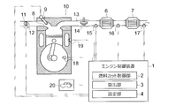
- FIG. 1 is a diagram schematically showing an engine 10 mounted on a vehicle and an engine control device 1 that controls the engine 10.
- the engine 10 has a fuel cut function for temporarily stopping fuel injection from an injector 9 provided in the intake port 8.
- a throttle valve 12 is interposed in the intake passage 11 of the engine 10.
- a turbocharger turbine 14, a pre-stage catalyst 6, and a post-stage catalyst 7 are disposed in the exhaust passage 13 in order from the upstream side.
- the front stage catalyst 6 and the rear stage catalyst 7 are both three-way catalysts and have a function of purifying nitrogen oxides, hydrocarbons, and carbon monoxide in an atmosphere near the theoretical air-fuel ratio. Further, these pre-stage catalyst 6 and post-stage catalyst 7 carry oxygen storage materials such as ceria-based materials, ceria / zirconia-based materials, and ceria / zirconia / alumina-based composite materials.
- the oxygen storage material has a characteristic of storing oxygen in a lean atmosphere and desorbing the stored oxygen during a lean operation in a rich atmosphere.
- the front catalyst 6 has a larger amount of noble metal supported on the catalyst than the rear catalyst 7.
- oxygen concentration sensors 15 to 17 for detecting the oxygen concentration in the exhaust gas are interposed.
- an upstream sensor 15 a sensor disposed between the front catalyst 6 and the rear catalyst 7 is also referred to as an intermediate sensor 16, and a sensor disposed downstream of the rear catalyst 7 is also referred to as a downstream sensor 17.
- Each of the upstream sensor 15, the intermediate sensor 16, and the downstream sensor 17 is a switching output type zirconia O 2 sensor that changes the sensor output V in a binary manner with an oxygen concentration corresponding to the theoretical air-fuel ratio as a threshold value.
- the sensor output V when the air-fuel ratio is rich is a predetermined value V 0 and the sensor output V when the air-fuel ratio is lean is zero. Since the sensor output V of the zirconia O 2 sensor changes depending on the temperature, the sensor output V may be corrected according to the exhaust gas temperature. Sensor outputs V from the oxygen concentration sensors 15 to 17 are transmitted to the engine control device 1.
- the engine 10 is provided with an engine speed sensor 18 that detects an engine speed N (engine speed) and a water temperature sensor 19 that detects a cooling water temperature W of the engine 10.
- a vehicle speed sensor 20 that detects the vehicle speed S is provided at an arbitrary position of the vehicle. Information on the engine speed N, the coolant temperature W, and the vehicle speed S detected by these sensors 18 to 20 is transmitted to the engine control device 1. Information on the opening degree of the throttle valve 12 (throttle opening degree) is also transmitted to the engine control apparatus 1.
- the engine control device 1 (exhaust gas purification control device) is a computer that comprehensively controls the engine 10, and is connected to a communication line of an in-vehicle network.
- the engine control device 1 is an electronic device (ECU) that integrates a microprocessor such as a CPU (Central Processing Unit), an MPU (Micro Processing Unit), a ROM (Read Only Memory), a RAM (Random Access Memory), a nonvolatile memory, , Electronic control device).
- the processor here is, for example, a processing device (processor) incorporating a control unit (control circuit), an arithmetic unit (arithmetic circuit), a cache memory (register), and the like.
- the ROM, RAM, and nonvolatile memory are memory devices that store programs and working data.
- the contents of control executed by the engine control apparatus 1 are recorded in ROM, RAM, nonvolatile memory, and removable media as firmware and application programs. When the program is executed, the contents of the program are expanded in the memory space in the RAM and
- the engine control device 1 has a function of controlling the fuel cut of the engine 10 according to the oxygen storage capacity A of the catalysts 6 and 7.
- the fuel supply from the injector 9 is not immediately interrupted, but the fuel supply is interrupted after a delay time B set according to the oxygen storage capacity A elapses. Is done. That is, if the start condition is not satisfied before the delay time B elapses with reference to the time when the fuel cut start condition is satisfied, the fuel cut is not performed. As a result, an instantaneous fuel cut that is shorter than the delay time B is suppressed.
- the engine control device 1 is provided with a fuel cut control unit 2, a calculation unit 3, and a setting unit 4. These indicate some functions of a program executed by the engine control apparatus 1 and are realized by software. However, some or all of the functions may be realized by hardware (electronic control circuit), or may be realized by using software and hardware together.
- the fuel cut control unit 2 controls the fuel cut of the engine 10, and performs the fuel cut according to the success or failure of a predetermined fuel cut condition.
- a predetermined fuel cut condition is, for example, that all the following conditions 1 to 4 are satisfied.
- the fuel cut is started when the delay time B elapses while these conditions are satisfied. Further, if any of the conditions is not satisfied during the fuel cut, the fuel cut ends. If any of the conditions is not satisfied during the delay time B, the fuel cut is not performed.
- Fuel cut condition 1.
- the engine speed N is not less than the first speed N 1 and not more than the second speed N 2 (N 1 ⁇ N ⁇ N 2 ) 2.
- the throttle opening is fully closed (below a predetermined opening).
- the vehicle speed S is a predetermined vehicle speed S 1 or more and a predetermined vehicle speed S 2 or less (S 1 ⁇ S ⁇ S 2 ). 4).
- the cooling water temperature W is equal to or higher than the predetermined water temperature W 1 (W 1 ⁇ W).
- the calculation unit 3 calculates the oxygen storage capacity A of the catalysts 6 and 7.
- the oxygen storage capacity A represents the weight of oxygen stored in the catalysts 6 and 7.
- the oxygen storage capacity A has a characteristic of decreasing as the catalysts 6 and 7 deteriorate. For example, when the catalysts 6 and 7 are new, the oxygen storage capacity A is the highest, and the oxygen storage capacity A decreases as the usage time of the catalysts 6 and 7 increases.
- the calculation unit 3 of the present embodiment calculates the oxygen storage capacity A of the catalysts 6 and 7 based on the sensor output V output from each oxygen concentration sensor 15 to 17 when the air-fuel ratio is changed. That is, the oxygen storage capacity A corresponding to the time (output inversion time) until the response time of the downstream sensor 17 is calculated with reference to the response time of the upstream sensor 15.
- the time from the response time of the upstream sensor 15 to the response time of the downstream sensor 17 is shorter, it is determined that the total oxygen storage capacity A of the catalyst 6 and the catalyst 7 is lower, and the oxygen storage capacity A having a lower value Is calculated.
- the oxygen storage capacity AD of only the rear catalyst 7 is calculated as a value obtained by subtracting the oxygen storage capacity A U of only the front catalyst 6 from the total oxygen storage capacity A.
- the air-fuel ratio is lean during the fuel cut.
- the air-fuel ratio is controlled to be near the stoichiometric range (for example, the feedback target air-fuel ratio corresponding to a slightly rich level).
- the change in the air-fuel ratio is detected as a change in oxygen concentration in each of the oxygen concentration sensors 15-17.
- the upstream sensor 15 Since the upstream sensor 15 is provided at a position closer to the engine 10 than the other sensors 16 and 17, the upstream sensor 15 outputs a predetermined value V 0 at time t 1 immediately after time t 0 .
- the intermediate sensor 16 outputs a predetermined value V 0 at time t 2 slightly delayed from time t 1 due to the influence of oxygen desorbed from the pre-stage catalyst 6.
- the downstream sensor 17, also receiving desorbed influence of oxygen from the rear catalyst 7, and outputs a predetermined value V 0 to the time t 3 when further delayed than the time t 2.
- the change in sensor output V of each sensor 15 to 17 is shown in FIG.
- the response time t 4 of the intermediate sensor 16 is earlier than the time t 2 before deterioration.
- the response time t 5 of the downstream sensor 17 also, a time earlier than the time t 3 before deterioration. Therefore, based on the time t 1, as an intermediate sensor 16, the time until the sensor output V of the downstream sensor 17 is changed shorter, it can be determined that the oxygen storage capacity A is low.
- the time t 0 may determine the level of oxygen storage capability A. Information on the oxygen storage capacity A calculated here is transmitted to the setting unit 4.
- the air-fuel ratio is changed from lean to near stoichiometric at time t 0 , but the change in sensor output V can also be detected when the air-fuel ratio is changed from near stoichiometric to the lean side. . Therefore, for example, by observing the change in the sensor output V immediately after the start of the fuel cut, it is possible to grasp the oxygen storage capacity A. Further, the sensor output V of each of the sensors 15 to 17 at the air-fuel ratio in the vicinity of the stoichiometry can change according to the temperature. Therefore, as shown in FIGS. 2B and 2C, a threshold value V 1 smaller than the predetermined value V 0 is set in advance, and the time when the sensor output V becomes equal to or higher than the threshold value V 1 is responded. It may be regarded as time.
- the setting unit 4 sets the length of the delay time B according to the oxygen storage capacity A calculated by the calculation unit 3.
- the delay time B is set according to the total oxygen storage capacity A of the catalyst 6 and the catalyst 7.
- the delay time B is set longer as the total oxygen storage capacity A of the catalyst 6 and the catalyst 7 is higher, and the delay time B is set shorter as the oxygen storage capacity A is lower.
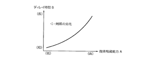
- a correspondence relationship between the oxygen storage capacity A and the delay time B is illustrated in FIG.
- the oxygen storage capacity A is low, the amount of oxygen desorbed from the catalysts 6 and 7 immediately after returning from the fuel cut decreases, so the exhaust purification performance does not deteriorate so much. Therefore, by setting the delay time B longer as the oxygen storage capacity A is higher, it is possible to efficiently suppress a decrease in exhaust purification performance due to desorbed oxygen.
- the delay time B may be set by using the oxygen storage capacities A U and A D of the respective catalysts 6 and 7 calculated by the calculation unit 3.
- the oxygen storage capacity AD of the rear catalyst 7 can be obtained by subtracting the oxygen storage capacity A U of the front catalyst 6 from the total oxygen storage capacity A.
- the first delay time B U corresponding to the oxygen storage capacity A U of the front catalyst 6 is set, and the second delay time B D corresponding to the oxygen storage capacity A D of the rear catalyst 7 is set.
- These added values can also be calculated as the delay time B.
- FIG. 4 is a flowchart illustrating a fuel cut control procedure. This flow is repeatedly performed at a predetermined cycle when, for example, the ignition key switch (main switch) of the vehicle is on.
- the symbol C in the flow is a counter value corresponding to the time during which the fuel cut condition continues to be established.
- the value C + 1 is substituted into the counter value C, and the elapsed time is measured (step A4).
- step A8 the control in this calculation cycle is completed.
- step A5 it is determined whether or not the elapsed time is equal to or longer than the delay time B (step A5). This determination can be replaced by determining whether or not the counter value C is equal to or greater than a predetermined value C 0 corresponding to the delay time B.
- step A9 it is determined whether or not the fuel cut end condition is satisfied.
- the fuel cut is continued (step A13).
- the delay time B setting flow is started (step A12)
- the control in the calculation cycle ends.
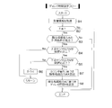
- FIG. 5 is a flowchart illustrating a procedure for setting the delay time B. This flow is started immediately after the fuel cut is completed, and is performed in parallel with the flow shown in FIG. 4 until the fuel cut is started again.
- the symbol T in the flow is a counter value corresponding to the output inversion time of the downstream sensor 17.
- step B4 whether the sensor output V of the upstream sensor 15 is the threshold value V 1 or more is determined.
- V ⁇ in case of V 1 completed control in the calculation cycle the flow proceeds to step B5 in the case of V ⁇ V 1.
- step B5 whether the sensor output V of the downstream sensor 17 is the threshold value V 1 or more is determined.
- the value T + 1 to the counter value T is substituted when a V ⁇ V 1, the elapsed time is measured (step B6).
- the oxygen storage capacity A of the catalyst 6, 7 is calculated by the calculating unit 3 (step B7).
- the setting unit 4 sets a delay time B based on the oxygen storage capacity A (step B8).
- the set delay time B is reflected in the determination content in step A5 in FIG. 4 (e.g., the value of the predetermined value C 0).
- a traveling state of a vehicle equipped with the engine control device 1 will be described with reference to FIGS. 6 (A) to 6 (E).
- Time t 10 the accelerator pedal is returned stepping in, the throttle opening is fully closed [FIG. 6 (B)], the engine rotational speed N gradually decreases [FIG 6 (D)], the vehicle speed S is reduced [FIG. 6 (E)].
- the fuel cut condition is satisfied.
- the fuel cut delay time B is not set, as shown by the broken line in FIG. 6A, outside air is introduced into the exhaust passage 13 to increase the air-fuel ratio, and the catalyst 6, A large amount of oxygen is stored in the oxygen storage material 7. Accordingly, as indicated by a broken line in FIG. 6 (C), the exhaust purification performance of the catalyst 6 is reduced immediately after the time t 13 where the fuel cut is finished, NOx exhaust concentration will temporarily increase.
- delay time B of the fuel cut is set delay time B of the fuel cut, the period from at least the time t 11 to time t 12 that the delay time B has elapsed, fuel cut is suspended without being started.
- the fuel cut execution period is shortened by the delay time B, and the amount of oxygen stored in the catalysts 6 and 7 is reduced. Therefore, as shown by a solid line in FIG. 6C, the exhaust purification performance of the catalysts 6 and 7 is improved as compared with the case where the delay time B is not set.
- the fuel cut-off condition at time t 16 is the same when satisfied, until the delay time B has elapsed, fuel cut is suspended without being started. Further, if the accelerator pedal is depressed during the delay time B and the throttle opening is increased, the fuel cut condition is not satisfied and the fuel cut is not started. If the fuel cut delay time B is not set, an instantaneous fuel cut that can be completed in less than a few seconds occurs as shown by the broken line in FIG. . Thus, as indicated by the broken line in FIG. 6 (C), the reduced exhaust gas purification performance after the time t 17 the throttle opening starts to increase, NOx exhaust concentration will temporarily increase. On the other hand, in this embodiment, such an instantaneous fuel cut is suppressed or prohibited. Thus, while suppressing the deterioration of fuel economy of the vehicle, the exhaust purification performance after the time t 17 can be maintained without lowering.
- the fuel cut delay time B is set based on the total oxygen storage capacity A of the catalyst 6 and the catalyst 7. Accordingly, the amount of time for performing the fuel cut can be determined in consideration of the amount of oxygen that can be desorbed from the catalysts 6 and 7 after the end of the fuel cut. Therefore, it is possible to accurately suppress the deterioration of the exhaust purification performance after returning from the fuel cut.
- the delay time B is extended as the oxygen storage capacity A is higher, and the delay time B is shortened as the oxygen storage capacity A is lower.
- This setting is derived from the fact that the higher the oxygen storage capacity A, the greater the amount of oxygen desorbed from the catalysts 6 and 7 when returning from the fuel cut, and the greater the adverse effect on the exhaust purification performance. That is, as the oxygen storage capacity A is higher, the delay time B is extended, so that the fuel cut can be made difficult to start, and the fuel cut execution time can be shortened. Therefore, the amount of oxygen desorbed from the catalysts 6 and 7 after returning from the fuel cut can be reduced, and the exhaust purification performance can be improved.
- the upstream sensor 15 disposed on the upstream side of the catalysts 6 and 7 and the downstream sensor 17 disposed on the downstream side are used.
- the oxygen storage capacity A is calculated.
- the response time difference here corresponds to the time from time t 1 to time t 3 (output inversion time) in FIG.
- the pre-stage catalyst 6 of the present embodiment has a larger amount of catalyst precious metal than the post-stage catalyst 7, the pre-stage catalyst 6 is larger than the post-stage catalyst 7 in terms of influence on the total exhaust purification performance.
- the engine control device 1 instead of referring to the total of oxygen storage capacity A of the catalyst 6 and the catalyst 7, it may be a case you want a oxygen storage capacity A U only precatalyst 6.
- the engine control device 1 using an intermediate sensor 16 that is disposed between the catalyst 6 and 7, it is possible to calculate the oxygen storage capacity A U of the pre-stage catalyst 6. That is, referring to the time (second output inversion time) from time t 1 to time t 2 in FIG.
- the oxygen storage capacity A U of the front catalyst 6 is lower as this time is shorter.
- the oxygen storage capacity A U of the front catalyst 6 may be calculated.
- the oxygen storage capacity AD of the rear catalyst 7 may be obtained by subtracting the oxygen storage capacity A U of the front catalyst 6 from the total oxygen storage capacity A.
- the calculation unit 3 that calculates the delay time B based on the oxygen storage capacity A of the catalysts 6 and 7 is exemplified, but it is also possible to calculate the delay time B in consideration of other parameters.
- the ease of adsorption of oxygen to the oxygen storage material can vary depending on the catalyst temperature, exhaust temperature, and ambient temperature (outside temperature). Therefore, the delay time B may be corrected in consideration of these various temperatures.
- the relationship between the oxygen storage capacity A and the delay time B is not limited to the relationship shown in FIG.
- the lower the oxygen storage capacity A the lower the exhaust purification performance of the catalysts 6 and 7. Therefore, by shortening the fuel cut execution time as much as possible, It may be possible to reduce the amount of oxygen released.
- the delay time B longer as the oxygen storage capacity A is lower, it is possible to suppress a decrease in exhaust purification performance due to desorbed oxygen.
- the oxygen storage capacity A is calculated based on the output reversal time when the air-fuel ratio is changed from lean to weakly rich (when returning from the fuel cut).
- the calculation method of A is not limited to this.
- the oxygen storage capacity A may be calculated based on the oscillation cycle (frequency) of the oxygen concentration detected on the downstream side of the catalysts 6 and 7 when the air-fuel ratio is vibrated near the stoichiometric range. This oscillation period becomes shorter as the oxygen storage capacity A of the catalysts 6 and 7 decreases.
- the vibration frequency on the downstream side of the catalysts 6 and 7 changes so as to approach the vibration frequency on the upstream side as the oxygen storage capacity A decreases. Therefore, the vibration period (frequency) of the oxygen concentration, the vibration frequency ratio in the upstream and downstream, and the like can be used as an index of the oxygen storage capacity A.
Landscapes
- Engineering & Computer Science (AREA)
- Chemical & Material Sciences (AREA)
- Combustion & Propulsion (AREA)
- Mechanical Engineering (AREA)
- General Engineering & Computer Science (AREA)
- Chemical Kinetics & Catalysis (AREA)
- Health & Medical Sciences (AREA)
- Toxicology (AREA)
- Materials Engineering (AREA)
- Electrical Control Of Air Or Fuel Supplied To Internal-Combustion Engine (AREA)
- Exhaust Gas After Treatment (AREA)
- Combined Controls Of Internal Combustion Engines (AREA)
Abstract
La présente invention concerne : une unité de commande de coupure de carburant (2) qui, lorsqu'une condition de coupure de carburant prescrite est satisfaite, coupe l'alimentation de carburant vers un moteur (10) après écoulement d'un délai prescrit (B) ; une unité de calcul (3) qui calcule la capacité d'absorption d'oxygène de catalyseurs (6, 7) interposés dans le système d'échappement du moteur (10) ; et une unité de réglage (4) qui règle la durée du délai (B) conformément à la capacité d'absorption d'oxygène calculée par l'unité de calcul (3).
Priority Applications (2)
| Application Number | Priority Date | Filing Date | Title |
|---|---|---|---|
| EP16845983.2A EP3351780B1 (fr) | 2015-09-16 | 2016-02-02 | Dispositif de commande de purification d'échappement |
| US15/757,736 US10526988B2 (en) | 2015-09-16 | 2016-02-02 | Controlling device for purifying exhaust gas purifying |
Applications Claiming Priority (2)
| Application Number | Priority Date | Filing Date | Title |
|---|---|---|---|
| JP2015-182547 | 2015-09-16 | ||
| JP2015182547A JP6597101B2 (ja) | 2015-09-16 | 2015-09-16 | 排気浄化制御装置 |
Publications (1)
| Publication Number | Publication Date |
|---|---|
| WO2017047109A1 true WO2017047109A1 (fr) | 2017-03-23 |
Family
ID=58288638
Family Applications (1)
| Application Number | Title | Priority Date | Filing Date |
|---|---|---|---|
| PCT/JP2016/053031 WO2017047109A1 (fr) | 2015-09-16 | 2016-02-02 | Dispositif de commande de purification d'échappement |
Country Status (4)
| Country | Link |
|---|---|
| US (1) | US10526988B2 (fr) |
| EP (1) | EP3351780B1 (fr) |
| JP (1) | JP6597101B2 (fr) |
| WO (1) | WO2017047109A1 (fr) |
Families Citing this family (6)
| Publication number | Priority date | Publication date | Assignee | Title |
|---|---|---|---|---|
| DE102016123426A1 (de) * | 2016-12-05 | 2018-06-07 | Volkswagen Aktiengesellschaft | Verfahren und Abgasanlage zur Prüfung eines Beladungszustands eines Partikelfilters |
| DE102018119010A1 (de) * | 2018-08-06 | 2020-02-06 | Volkswagen Aktiengesellschaft | Verfahren und Vorrichtung zur Abgasnachbehandlung eines Verbrennungsmotors |
| JP7077883B2 (ja) | 2018-09-06 | 2022-05-31 | トヨタ自動車株式会社 | 内燃機関の排気浄化装置 |
| KR102654452B1 (ko) | 2019-02-21 | 2024-04-03 | 현대자동차 주식회사 | 자동차의 배기가스 정화장치 및 그 제어방법 |
| FR3134149A1 (fr) * | 2022-03-29 | 2023-10-06 | Renault S.A.S | Système d’injection configuré pour la stabilisation de la valeur de la richesse d’un mélange air-carburant en fonction de la capacité de stockage en oxygène courante d’un catalyseur |
| CN118049302B (zh) * | 2024-04-16 | 2024-06-28 | 江苏创泰特钢制品有限公司 | 一种汽车尾气净化装置 |
Citations (3)
| Publication number | Priority date | Publication date | Assignee | Title |
|---|---|---|---|---|
| JP2011106352A (ja) * | 2009-11-18 | 2011-06-02 | Nissan Motor Co Ltd | 内燃機関の燃料噴射制御装置 |
| JP2014181623A (ja) * | 2013-03-19 | 2014-09-29 | Hitachi Automotive Systems Ltd | 内燃機関の制御装置 |
| JP2015010489A (ja) * | 2013-06-27 | 2015-01-19 | ダイハツ工業株式会社 | 内燃機関の制御装置 |
Family Cites Families (13)
| Publication number | Priority date | Publication date | Assignee | Title |
|---|---|---|---|---|
| JPS58110805A (ja) * | 1981-12-24 | 1983-07-01 | Honda Motor Co Ltd | 自動二輪車用内燃機関における二次空気供給およびスロツトルオプナの作動制御装置 |
| US6667018B2 (en) * | 1994-07-05 | 2003-12-23 | Ngk Insulators, Ltd. | Catalyst-adsorbent for purification of exhaust gases and method for purification of exhaust gases |
| JP3966014B2 (ja) * | 2002-02-25 | 2007-08-29 | 株式会社デンソー | 内燃機関の排気浄化装置 |
| JP2005248781A (ja) * | 2004-03-03 | 2005-09-15 | Toyota Motor Corp | 内燃機関の燃料カット制御装置 |
| JP4671130B2 (ja) | 2006-07-21 | 2011-04-13 | トヨタ自動車株式会社 | 内燃機関の触媒劣化検出装置 |
| FR2905371B1 (fr) * | 2006-08-31 | 2010-11-05 | Rhodia Recherches & Tech | Composition a reductibilite elevee a base d'un oxyde de cerium nanometrique sur un support, procede de preparation et utilisation comme catalyseur |
| JP2010084750A (ja) * | 2008-09-04 | 2010-04-15 | Denso Corp | 排気浄化用触媒の劣化診断装置 |
| CN102470363B (zh) * | 2009-07-24 | 2015-01-28 | 株式会社科特拉 | 废气净化用催化剂 |
| JP5029718B2 (ja) * | 2010-03-18 | 2012-09-19 | トヨタ自動車株式会社 | 内燃機関の排気浄化装置 |
| US8826642B2 (en) * | 2010-04-13 | 2014-09-09 | Toyota Jidosha Kabushiki Kaisha | Device for purifying exhaust gas of internal combustion engine |
| JP5796635B2 (ja) * | 2011-11-28 | 2015-10-21 | 日産自動車株式会社 | 内燃機関の燃料カット制御装置及び燃料カット制御方法 |
| JP5642107B2 (ja) * | 2012-03-30 | 2014-12-17 | 本田技研工業株式会社 | 鞍乗型車両用排気ガス浄化装置及びそれに用いるパラジウム単層触媒 |
| JP2015071985A (ja) * | 2013-10-03 | 2015-04-16 | トヨタ自動車株式会社 | 内燃機関の制御装置 |
-
2015
- 2015-09-16 JP JP2015182547A patent/JP6597101B2/ja active Active
-
2016
- 2016-02-02 WO PCT/JP2016/053031 patent/WO2017047109A1/fr unknown
- 2016-02-02 US US15/757,736 patent/US10526988B2/en active Active
- 2016-02-02 EP EP16845983.2A patent/EP3351780B1/fr active Active
Patent Citations (3)
| Publication number | Priority date | Publication date | Assignee | Title |
|---|---|---|---|---|
| JP2011106352A (ja) * | 2009-11-18 | 2011-06-02 | Nissan Motor Co Ltd | 内燃機関の燃料噴射制御装置 |
| JP2014181623A (ja) * | 2013-03-19 | 2014-09-29 | Hitachi Automotive Systems Ltd | 内燃機関の制御装置 |
| JP2015010489A (ja) * | 2013-06-27 | 2015-01-19 | ダイハツ工業株式会社 | 内燃機関の制御装置 |
Also Published As
| Publication number | Publication date |
|---|---|
| EP3351780B1 (fr) | 2020-08-26 |
| JP2017057777A (ja) | 2017-03-23 |
| JP6597101B2 (ja) | 2019-10-30 |
| EP3351780A4 (fr) | 2019-03-20 |
| US20180347492A1 (en) | 2018-12-06 |
| US10526988B2 (en) | 2020-01-07 |
| EP3351780A1 (fr) | 2018-07-25 |
Similar Documents
| Publication | Publication Date | Title |
|---|---|---|
| JP6597101B2 (ja) | 排気浄化制御装置 | |
| JP5029718B2 (ja) | 内燃機関の排気浄化装置 | |
| JP6256240B2 (ja) | 内燃機関の制御装置 | |
| US10598063B2 (en) | Exhaust purification system of internal combustion engine | |
| JP2000345830A (ja) | 内燃機関の排気浄化装置 | |
| JP5338974B2 (ja) | 内燃機関の排気浄化装置 | |
| JP2017031946A (ja) | 内燃機関 | |
| JP2018178762A (ja) | 内燃機関の排気浄化装置 | |
| JP6056726B2 (ja) | 内燃機関の制御装置 | |
| JP6248978B2 (ja) | 内燃機関の制御装置 | |
| JP2007239698A (ja) | 内燃機関の空燃比制御装置 | |
| KR20180068164A (ko) | 배기가스 정화장치 및 그 제어 방법 | |
| JP4938532B2 (ja) | 内燃機関の空燃比制御装置 | |
| JP2017115621A (ja) | 排気浄化装置 | |
| JP2015121118A (ja) | 内燃機関の排気浄化装置 | |
| JP4366976B2 (ja) | 排気ガスセンサの異常検出装置 | |
| JP6613750B2 (ja) | 排気浄化制御装置 | |
| JP6244626B2 (ja) | ディーゼルエンジンの排気後処理装置 | |
| US11193408B2 (en) | Reactivation control apparatus and method | |
| JP2007092609A (ja) | 内燃機関の制御装置 | |
| JP6380264B2 (ja) | 酸素センサの異常診断装置 | |
| JP2019065797A (ja) | 内燃機関の排気浄化装置 | |
| JP2004232576A (ja) | 内燃機関の排気浄化装置 | |
| JP2004060613A (ja) | 内燃機関の空燃比制御装置 | |
| JP2004285841A (ja) | 内燃機関の排気浄化装置 |
Legal Events
| Date | Code | Title | Description |
|---|---|---|---|
| 121 | Ep: the epo has been informed by wipo that ep was designated in this application |
Ref document number: 16845983 Country of ref document: EP Kind code of ref document: A1 |
|
| NENP | Non-entry into the national phase |
Ref country code: DE |