WO2017047109A1 - 排気浄化制御装置 - Google Patents
排気浄化制御装置 Download PDFInfo
- Publication number
- WO2017047109A1 WO2017047109A1 PCT/JP2016/053031 JP2016053031W WO2017047109A1 WO 2017047109 A1 WO2017047109 A1 WO 2017047109A1 JP 2016053031 W JP2016053031 W JP 2016053031W WO 2017047109 A1 WO2017047109 A1 WO 2017047109A1
- Authority
- WO
- WIPO (PCT)
- Prior art keywords
- catalyst
- oxygen storage
- storage capacity
- fuel cut
- time
- Prior art date
Links
Images

Classifications
-
- F—MECHANICAL ENGINEERING; LIGHTING; HEATING; WEAPONS; BLASTING
- F02—COMBUSTION ENGINES; HOT-GAS OR COMBUSTION-PRODUCT ENGINE PLANTS
- F02D—CONTROLLING COMBUSTION ENGINES
- F02D41/00—Electrical control of supply of combustible mixture or its constituents
- F02D41/02—Circuit arrangements for generating control signals
- F02D41/04—Introducing corrections for particular operating conditions
- F02D41/12—Introducing corrections for particular operating conditions for deceleration
- F02D41/123—Introducing corrections for particular operating conditions for deceleration the fuel injection being cut-off
-
- F—MECHANICAL ENGINEERING; LIGHTING; HEATING; WEAPONS; BLASTING
- F01—MACHINES OR ENGINES IN GENERAL; ENGINE PLANTS IN GENERAL; STEAM ENGINES
- F01N—GAS-FLOW SILENCERS OR EXHAUST APPARATUS FOR MACHINES OR ENGINES IN GENERAL; GAS-FLOW SILENCERS OR EXHAUST APPARATUS FOR INTERNAL COMBUSTION ENGINES
- F01N11/00—Monitoring or diagnostic devices for exhaust-gas treatment apparatus, e.g. for catalytic activity
- F01N11/002—Monitoring or diagnostic devices for exhaust-gas treatment apparatus, e.g. for catalytic activity the diagnostic devices measuring or estimating temperature or pressure in, or downstream of the exhaust apparatus
-
- F—MECHANICAL ENGINEERING; LIGHTING; HEATING; WEAPONS; BLASTING
- F01—MACHINES OR ENGINES IN GENERAL; ENGINE PLANTS IN GENERAL; STEAM ENGINES
- F01N—GAS-FLOW SILENCERS OR EXHAUST APPARATUS FOR MACHINES OR ENGINES IN GENERAL; GAS-FLOW SILENCERS OR EXHAUST APPARATUS FOR INTERNAL COMBUSTION ENGINES
- F01N11/00—Monitoring or diagnostic devices for exhaust-gas treatment apparatus, e.g. for catalytic activity
- F01N11/007—Monitoring or diagnostic devices for exhaust-gas treatment apparatus, e.g. for catalytic activity the diagnostic devices measuring oxygen or air concentration downstream of the exhaust apparatus
-
- F—MECHANICAL ENGINEERING; LIGHTING; HEATING; WEAPONS; BLASTING
- F01—MACHINES OR ENGINES IN GENERAL; ENGINE PLANTS IN GENERAL; STEAM ENGINES
- F01N—GAS-FLOW SILENCERS OR EXHAUST APPARATUS FOR MACHINES OR ENGINES IN GENERAL; GAS-FLOW SILENCERS OR EXHAUST APPARATUS FOR INTERNAL COMBUSTION ENGINES
- F01N13/00—Exhaust or silencing apparatus characterised by constructional features ; Exhaust or silencing apparatus, or parts thereof, having pertinent characteristics not provided for in, or of interest apart from, groups F01N1/00 - F01N5/00, F01N9/00, F01N11/00
- F01N13/009—Exhaust or silencing apparatus characterised by constructional features ; Exhaust or silencing apparatus, or parts thereof, having pertinent characteristics not provided for in, or of interest apart from, groups F01N1/00 - F01N5/00, F01N9/00, F01N11/00 having two or more separate purifying devices arranged in series
- F01N13/0093—Exhaust or silencing apparatus characterised by constructional features ; Exhaust or silencing apparatus, or parts thereof, having pertinent characteristics not provided for in, or of interest apart from, groups F01N1/00 - F01N5/00, F01N9/00, F01N11/00 having two or more separate purifying devices arranged in series the purifying devices are of the same type
-
- F—MECHANICAL ENGINEERING; LIGHTING; HEATING; WEAPONS; BLASTING
- F01—MACHINES OR ENGINES IN GENERAL; ENGINE PLANTS IN GENERAL; STEAM ENGINES
- F01N—GAS-FLOW SILENCERS OR EXHAUST APPARATUS FOR MACHINES OR ENGINES IN GENERAL; GAS-FLOW SILENCERS OR EXHAUST APPARATUS FOR INTERNAL COMBUSTION ENGINES
- F01N3/00—Exhaust or silencing apparatus having means for purifying, rendering innocuous, or otherwise treating exhaust
- F01N3/08—Exhaust or silencing apparatus having means for purifying, rendering innocuous, or otherwise treating exhaust for rendering innocuous
- F01N3/10—Exhaust or silencing apparatus having means for purifying, rendering innocuous, or otherwise treating exhaust for rendering innocuous by thermal or catalytic conversion of noxious components of exhaust
- F01N3/101—Three-way catalysts
-
- F—MECHANICAL ENGINEERING; LIGHTING; HEATING; WEAPONS; BLASTING
- F01—MACHINES OR ENGINES IN GENERAL; ENGINE PLANTS IN GENERAL; STEAM ENGINES
- F01N—GAS-FLOW SILENCERS OR EXHAUST APPARATUS FOR MACHINES OR ENGINES IN GENERAL; GAS-FLOW SILENCERS OR EXHAUST APPARATUS FOR INTERNAL COMBUSTION ENGINES
- F01N3/00—Exhaust or silencing apparatus having means for purifying, rendering innocuous, or otherwise treating exhaust
- F01N3/08—Exhaust or silencing apparatus having means for purifying, rendering innocuous, or otherwise treating exhaust for rendering innocuous
- F01N3/10—Exhaust or silencing apparatus having means for purifying, rendering innocuous, or otherwise treating exhaust for rendering innocuous by thermal or catalytic conversion of noxious components of exhaust
- F01N3/18—Exhaust or silencing apparatus having means for purifying, rendering innocuous, or otherwise treating exhaust for rendering innocuous by thermal or catalytic conversion of noxious components of exhaust characterised by methods of operation; Control
- F01N3/20—Exhaust or silencing apparatus having means for purifying, rendering innocuous, or otherwise treating exhaust for rendering innocuous by thermal or catalytic conversion of noxious components of exhaust characterised by methods of operation; Control specially adapted for catalytic conversion ; Methods of operation or control of catalytic converters
-
- F—MECHANICAL ENGINEERING; LIGHTING; HEATING; WEAPONS; BLASTING
- F01—MACHINES OR ENGINES IN GENERAL; ENGINE PLANTS IN GENERAL; STEAM ENGINES
- F01N—GAS-FLOW SILENCERS OR EXHAUST APPARATUS FOR MACHINES OR ENGINES IN GENERAL; GAS-FLOW SILENCERS OR EXHAUST APPARATUS FOR INTERNAL COMBUSTION ENGINES
- F01N3/00—Exhaust or silencing apparatus having means for purifying, rendering innocuous, or otherwise treating exhaust
- F01N3/08—Exhaust or silencing apparatus having means for purifying, rendering innocuous, or otherwise treating exhaust for rendering innocuous
- F01N3/10—Exhaust or silencing apparatus having means for purifying, rendering innocuous, or otherwise treating exhaust for rendering innocuous by thermal or catalytic conversion of noxious components of exhaust
- F01N3/24—Exhaust or silencing apparatus having means for purifying, rendering innocuous, or otherwise treating exhaust for rendering innocuous by thermal or catalytic conversion of noxious components of exhaust characterised by constructional aspects of converting apparatus
- F01N3/28—Construction of catalytic reactors
-
- F—MECHANICAL ENGINEERING; LIGHTING; HEATING; WEAPONS; BLASTING
- F01—MACHINES OR ENGINES IN GENERAL; ENGINE PLANTS IN GENERAL; STEAM ENGINES
- F01N—GAS-FLOW SILENCERS OR EXHAUST APPARATUS FOR MACHINES OR ENGINES IN GENERAL; GAS-FLOW SILENCERS OR EXHAUST APPARATUS FOR INTERNAL COMBUSTION ENGINES
- F01N9/00—Electrical control of exhaust gas treating apparatus
-
- F—MECHANICAL ENGINEERING; LIGHTING; HEATING; WEAPONS; BLASTING
- F02—COMBUSTION ENGINES; HOT-GAS OR COMBUSTION-PRODUCT ENGINE PLANTS
- F02D—CONTROLLING COMBUSTION ENGINES
- F02D41/00—Electrical control of supply of combustible mixture or its constituents
- F02D41/02—Circuit arrangements for generating control signals
- F02D41/021—Introducing corrections for particular conditions exterior to the engine
- F02D41/0235—Introducing corrections for particular conditions exterior to the engine in relation with the state of the exhaust gas treating apparatus
- F02D41/0295—Control according to the amount of oxygen that is stored on the exhaust gas treating apparatus
-
- F—MECHANICAL ENGINEERING; LIGHTING; HEATING; WEAPONS; BLASTING
- F02—COMBUSTION ENGINES; HOT-GAS OR COMBUSTION-PRODUCT ENGINE PLANTS
- F02D—CONTROLLING COMBUSTION ENGINES
- F02D41/00—Electrical control of supply of combustible mixture or its constituents
- F02D41/02—Circuit arrangements for generating control signals
- F02D41/04—Introducing corrections for particular operating conditions
- F02D41/12—Introducing corrections for particular operating conditions for deceleration
-
- F—MECHANICAL ENGINEERING; LIGHTING; HEATING; WEAPONS; BLASTING
- F02—COMBUSTION ENGINES; HOT-GAS OR COMBUSTION-PRODUCT ENGINE PLANTS
- F02D—CONTROLLING COMBUSTION ENGINES
- F02D41/00—Electrical control of supply of combustible mixture or its constituents
- F02D41/02—Circuit arrangements for generating control signals
- F02D41/14—Introducing closed-loop corrections
- F02D41/1438—Introducing closed-loop corrections using means for determining characteristics of the combustion gases; Sensors therefor
- F02D41/1439—Introducing closed-loop corrections using means for determining characteristics of the combustion gases; Sensors therefor characterised by the position of the sensor
- F02D41/1441—Plural sensors
-
- F—MECHANICAL ENGINEERING; LIGHTING; HEATING; WEAPONS; BLASTING
- F02—COMBUSTION ENGINES; HOT-GAS OR COMBUSTION-PRODUCT ENGINE PLANTS
- F02D—CONTROLLING COMBUSTION ENGINES
- F02D41/00—Electrical control of supply of combustible mixture or its constituents
- F02D41/02—Circuit arrangements for generating control signals
- F02D41/14—Introducing closed-loop corrections
- F02D41/1438—Introducing closed-loop corrections using means for determining characteristics of the combustion gases; Sensors therefor
- F02D41/1444—Introducing closed-loop corrections using means for determining characteristics of the combustion gases; Sensors therefor characterised by the characteristics of the combustion gases
- F02D41/1454—Introducing closed-loop corrections using means for determining characteristics of the combustion gases; Sensors therefor characterised by the characteristics of the combustion gases the characteristics being an oxygen content or concentration or the air-fuel ratio
-
- F—MECHANICAL ENGINEERING; LIGHTING; HEATING; WEAPONS; BLASTING
- F01—MACHINES OR ENGINES IN GENERAL; ENGINE PLANTS IN GENERAL; STEAM ENGINES
- F01N—GAS-FLOW SILENCERS OR EXHAUST APPARATUS FOR MACHINES OR ENGINES IN GENERAL; GAS-FLOW SILENCERS OR EXHAUST APPARATUS FOR INTERNAL COMBUSTION ENGINES
- F01N2550/00—Monitoring or diagnosing the deterioration of exhaust systems
- F01N2550/02—Catalytic activity of catalytic converters
-
- F—MECHANICAL ENGINEERING; LIGHTING; HEATING; WEAPONS; BLASTING
- F01—MACHINES OR ENGINES IN GENERAL; ENGINE PLANTS IN GENERAL; STEAM ENGINES
- F01N—GAS-FLOW SILENCERS OR EXHAUST APPARATUS FOR MACHINES OR ENGINES IN GENERAL; GAS-FLOW SILENCERS OR EXHAUST APPARATUS FOR INTERNAL COMBUSTION ENGINES
- F01N2560/00—Exhaust systems with means for detecting or measuring exhaust gas components or characteristics
- F01N2560/02—Exhaust systems with means for detecting or measuring exhaust gas components or characteristics the means being an exhaust gas sensor
- F01N2560/025—Exhaust systems with means for detecting or measuring exhaust gas components or characteristics the means being an exhaust gas sensor for measuring or detecting O2, e.g. lambda sensors
-
- F—MECHANICAL ENGINEERING; LIGHTING; HEATING; WEAPONS; BLASTING
- F01—MACHINES OR ENGINES IN GENERAL; ENGINE PLANTS IN GENERAL; STEAM ENGINES
- F01N—GAS-FLOW SILENCERS OR EXHAUST APPARATUS FOR MACHINES OR ENGINES IN GENERAL; GAS-FLOW SILENCERS OR EXHAUST APPARATUS FOR INTERNAL COMBUSTION ENGINES
- F01N2570/00—Exhaust treating apparatus eliminating, absorbing or adsorbing specific elements or compounds
- F01N2570/16—Oxygen
-
- F—MECHANICAL ENGINEERING; LIGHTING; HEATING; WEAPONS; BLASTING
- F01—MACHINES OR ENGINES IN GENERAL; ENGINE PLANTS IN GENERAL; STEAM ENGINES
- F01N—GAS-FLOW SILENCERS OR EXHAUST APPARATUS FOR MACHINES OR ENGINES IN GENERAL; GAS-FLOW SILENCERS OR EXHAUST APPARATUS FOR INTERNAL COMBUSTION ENGINES
- F01N2900/00—Details of electrical control or of the monitoring of the exhaust gas treating apparatus
- F01N2900/06—Parameters used for exhaust control or diagnosing
- F01N2900/08—Parameters used for exhaust control or diagnosing said parameters being related to the engine
-
- F—MECHANICAL ENGINEERING; LIGHTING; HEATING; WEAPONS; BLASTING
- F01—MACHINES OR ENGINES IN GENERAL; ENGINE PLANTS IN GENERAL; STEAM ENGINES
- F01N—GAS-FLOW SILENCERS OR EXHAUST APPARATUS FOR MACHINES OR ENGINES IN GENERAL; GAS-FLOW SILENCERS OR EXHAUST APPARATUS FOR INTERNAL COMBUSTION ENGINES
- F01N2900/00—Details of electrical control or of the monitoring of the exhaust gas treating apparatus
- F01N2900/06—Parameters used for exhaust control or diagnosing
- F01N2900/16—Parameters used for exhaust control or diagnosing said parameters being related to the exhaust apparatus, e.g. particulate filter or catalyst
- F01N2900/1602—Temperature of exhaust gas apparatus
-
- F—MECHANICAL ENGINEERING; LIGHTING; HEATING; WEAPONS; BLASTING
- F01—MACHINES OR ENGINES IN GENERAL; ENGINE PLANTS IN GENERAL; STEAM ENGINES
- F01N—GAS-FLOW SILENCERS OR EXHAUST APPARATUS FOR MACHINES OR ENGINES IN GENERAL; GAS-FLOW SILENCERS OR EXHAUST APPARATUS FOR INTERNAL COMBUSTION ENGINES
- F01N2900/00—Details of electrical control or of the monitoring of the exhaust gas treating apparatus
- F01N2900/06—Parameters used for exhaust control or diagnosing
- F01N2900/16—Parameters used for exhaust control or diagnosing said parameters being related to the exhaust apparatus, e.g. particulate filter or catalyst
- F01N2900/1621—Catalyst conversion efficiency
-
- F—MECHANICAL ENGINEERING; LIGHTING; HEATING; WEAPONS; BLASTING
- F01—MACHINES OR ENGINES IN GENERAL; ENGINE PLANTS IN GENERAL; STEAM ENGINES
- F01N—GAS-FLOW SILENCERS OR EXHAUST APPARATUS FOR MACHINES OR ENGINES IN GENERAL; GAS-FLOW SILENCERS OR EXHAUST APPARATUS FOR INTERNAL COMBUSTION ENGINES
- F01N2900/00—Details of electrical control or of the monitoring of the exhaust gas treating apparatus
- F01N2900/06—Parameters used for exhaust control or diagnosing
- F01N2900/16—Parameters used for exhaust control or diagnosing said parameters being related to the exhaust apparatus, e.g. particulate filter or catalyst
- F01N2900/1624—Catalyst oxygen storage capacity
-
- F—MECHANICAL ENGINEERING; LIGHTING; HEATING; WEAPONS; BLASTING
- F02—COMBUSTION ENGINES; HOT-GAS OR COMBUSTION-PRODUCT ENGINE PLANTS
- F02D—CONTROLLING COMBUSTION ENGINES
- F02D41/00—Electrical control of supply of combustible mixture or its constituents
- F02D41/02—Circuit arrangements for generating control signals
- F02D41/14—Introducing closed-loop corrections
- F02D41/1401—Introducing closed-loop corrections characterised by the control or regulation method
- F02D2041/1413—Controller structures or design
- F02D2041/1431—Controller structures or design the system including an input-output delay
-
- F—MECHANICAL ENGINEERING; LIGHTING; HEATING; WEAPONS; BLASTING
- F02—COMBUSTION ENGINES; HOT-GAS OR COMBUSTION-PRODUCT ENGINE PLANTS
- F02D—CONTROLLING COMBUSTION ENGINES
- F02D2200/00—Input parameters for engine control
- F02D2200/02—Input parameters for engine control the parameters being related to the engine
- F02D2200/08—Exhaust gas treatment apparatus parameters
- F02D2200/0802—Temperature of the exhaust gas treatment apparatus
-
- Y—GENERAL TAGGING OF NEW TECHNOLOGICAL DEVELOPMENTS; GENERAL TAGGING OF CROSS-SECTIONAL TECHNOLOGIES SPANNING OVER SEVERAL SECTIONS OF THE IPC; TECHNICAL SUBJECTS COVERED BY FORMER USPC CROSS-REFERENCE ART COLLECTIONS [XRACs] AND DIGESTS
- Y02—TECHNOLOGIES OR APPLICATIONS FOR MITIGATION OR ADAPTATION AGAINST CLIMATE CHANGE
- Y02T—CLIMATE CHANGE MITIGATION TECHNOLOGIES RELATED TO TRANSPORTATION
- Y02T10/00—Road transport of goods or passengers
- Y02T10/10—Internal combustion engine [ICE] based vehicles
- Y02T10/12—Improving ICE efficiencies
-
- Y—GENERAL TAGGING OF NEW TECHNOLOGICAL DEVELOPMENTS; GENERAL TAGGING OF CROSS-SECTIONAL TECHNOLOGIES SPANNING OVER SEVERAL SECTIONS OF THE IPC; TECHNICAL SUBJECTS COVERED BY FORMER USPC CROSS-REFERENCE ART COLLECTIONS [XRACs] AND DIGESTS
- Y02—TECHNOLOGIES OR APPLICATIONS FOR MITIGATION OR ADAPTATION AGAINST CLIMATE CHANGE
- Y02T—CLIMATE CHANGE MITIGATION TECHNOLOGIES RELATED TO TRANSPORTATION
- Y02T10/00—Road transport of goods or passengers
- Y02T10/10—Internal combustion engine [ICE] based vehicles
- Y02T10/40—Engine management systems
Definitions
- the present invention relates to a vehicle exhaust gas purification control apparatus in which a catalyst containing an oxygen storage material is interposed in an engine exhaust system.
- a three-way catalyst containing an oxygen storage material is known as one of the catalysts interposed in the exhaust system of a gasoline vehicle.
- a three-way catalyst is a catalyst that simultaneously promotes a reduction reaction of nitrogen oxides (NOx), an oxidation reaction of hydrocarbons (HnCm), and an oxidation reaction of carbon monoxide (CO) in an atmosphere near the theoretical air-fuel ratio.
- the oxygen storage material is a promoter having a characteristic of storing oxygen in a lean atmosphere and desorbing the stored oxygen during a lean operation in a rich atmosphere.
- oxygen storage materials include ceria (CeO 2 ), ceria-zirconia composite material (CeO 2 -ZrO 2 ), alumina-ceria-zirconia composite material (Al 2 O 3 -CeO 2 -ZrO 2 ), these Examples include a material in which the second and third element components are combined with the material.
- these oxygen storage materials include a material in which the second and third element components are combined with the material.
- a control called fuel cut may be performed on an engine equipped with the above catalyst in an exhaust system.
- the fuel cut is a control for temporarily stopping the fuel supply to the engine when a predetermined fuel cut condition is satisfied.
- This control is performed, for example, during inertia running or deceleration of the vehicle, and functions to suppress wasteful fuel consumption. That is, the fuel consumption of the vehicle can be improved by performing the fuel cut.
- the amount of oxygen stored in the oxygen storage material of the catalyst may become excessive.
- Such excessive stored oxygen can reduce the exhaust purification performance when returning from the fuel cut. That is, when the engine returns from the fuel cut, the amount of oxygen desorbed from the oxygen storage material temporarily increases, so the air-fuel ratio becomes slightly leaner and the nitrogen oxide purification rate tends to decrease.
- the fuel injection amount in order to set the air-fuel ratio around the catalyst to the stoichiometric air-fuel ratio in consideration of the amount of desorbed oxygen, the fuel injection amount must be increased. As a result, the total fuel injection amount increases, and the fuel efficiency improvement effect due to the fuel cut can be offset.
- One of the objects of the present invention was created in view of the above-described problems, and provides an exhaust purification control device that can improve fuel efficiency while suppressing a decrease in exhaust purification performance of a catalyst. is there. It should be noted that the present invention is not limited to this purpose, and is an operational effect that is derived from each configuration shown in “Mode for Carrying Out the Invention” to be described later. Can be positioned as a purpose.
- the exhaust purification control device disclosed herein includes a fuel cut control unit that shuts off fuel supply to the engine after a predetermined delay time has elapsed when a predetermined fuel cut condition is satisfied. Further, a calculation unit is provided for calculating an oxygen storage capacity (for example, an index value representing the oxygen storage capacity) of the catalyst including the oxygen storage material interposed in the exhaust system of the engine. Furthermore, a setting unit is provided for setting the length of the delay time according to the oxygen storage capacity calculated by the calculation unit.
- the oxygen storage capacity preferably represents the weight of oxygen stored in the catalyst. For example, it is preferable that the oxygen storage capacity is the highest when the catalyst is new, and that the oxygen storage capacity decreases as the catalyst is used for a long time.
- the setting unit shortens the delay time as the oxygen storage capacity is lower.
- the delay time when the catalyst is new is set to be the longest, and the delay time is set to be shorter as the catalyst is used longer.
- the calculation unit determines that the oxygen storage capacity is lower as the output inversion time from the response time of the upstream sensor to the response time of the downstream sensor with respect to a change in the air-fuel ratio is shorter.
- the catalyst has a front catalyst located upstream of the exhaust system and a rear catalyst located downstream. Moreover, it is preferable to provide an intermediate sensor for detecting an oxygen concentration between the front catalyst and the rear catalyst. In this case, it is preferable that the calculation unit determines that the oxygen storage capacity is lower as the second output inversion time from the response time of the upstream sensor to the response time of the intermediate sensor with respect to the change in air-fuel ratio is shorter. . (5) It is preferable that the calculation unit calculates the oxygen storage capacity in the previous period based on the degree of aging of the catalyst. For example, the oxygen storage capacity in the previous period may be calculated based on the usage time of the catalyst (accumulated value obtained by accumulating the usage time from when the catalyst is new).
- the calculation unit calculates the oxygen storage capacity when a condition that the operation state of the engine is stable for a predetermined period is satisfied. In other words, “the operating state of the engine is stable for a predetermined period” is preferably included in the condition for calculating the oxygen storage capacity. (7) It is preferable that the calculation unit calculates the oxygen storage capacity when a condition that the temperature of the catalyst is within a predetermined temperature range is satisfied. In other words, “the temperature of the catalyst is within a predetermined temperature range” is preferably included in the condition for calculating the oxygen storage capacity.
- the amount of oxygen stored in the catalyst can be adjusted, and the deterioration of the exhaust purification performance of the catalyst can be suppressed.
- the occlusion of oxygen it is possible to suppress the enrichment of the combustion air-fuel ratio of the engine that is performed after returning from the fuel cut, and it is possible to improve fuel efficiency.
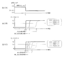
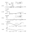
- FIG. 2A is a graph for explaining a method for calculating the oxygen storage capacity of a catalyst
- FIG. 2A is the air-fuel ratio change at the time of fuel cut return
- FIGS. 2B and 2C are output characteristics of the oxygen concentration sensor. Represents. It is a graph which shows the relationship between the oxygen storage capacity of a catalyst, and the delay time of a fuel cut. It is a flowchart which illustrates the control procedure of a fuel cut. It is a flowchart which illustrates the setting procedure of delay time.
- FIGS. 6A and 6B are time charts for explaining the action and effect of control by the exhaust purification control device, FIG. 6A is the air-fuel ratio, FIG. 6B is the throttle opening, FIG. 6C is the NOx emission concentration, FIG. 6 (D) corresponds to the engine speed, and FIG. 6 (E) corresponds to the vehicle speed.
- an exhaust purification control apparatus as an embodiment will be described.
- the minimum configuration of the exhaust purification control device can be realized only by the engine control device 1 described below, the entire system including the engine control device 1 and the oxygen concentration sensors 15 to 17 may be realized as the exhaust purification control device.
- the embodiment described below is merely an example, and there is no intention to exclude various modifications and technical applications that are not explicitly described in the following embodiment.
- Each configuration of the present embodiment can be implemented with various modifications without departing from the spirit thereof. Further, they can be selected as necessary, or can be appropriately combined.
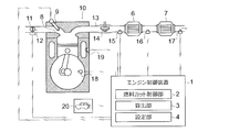
- FIG. 1 is a diagram schematically showing an engine 10 mounted on a vehicle and an engine control device 1 that controls the engine 10.
- the engine 10 has a fuel cut function for temporarily stopping fuel injection from an injector 9 provided in the intake port 8.
- a throttle valve 12 is interposed in the intake passage 11 of the engine 10.
- a turbocharger turbine 14, a pre-stage catalyst 6, and a post-stage catalyst 7 are disposed in the exhaust passage 13 in order from the upstream side.
- the front stage catalyst 6 and the rear stage catalyst 7 are both three-way catalysts and have a function of purifying nitrogen oxides, hydrocarbons, and carbon monoxide in an atmosphere near the theoretical air-fuel ratio. Further, these pre-stage catalyst 6 and post-stage catalyst 7 carry oxygen storage materials such as ceria-based materials, ceria / zirconia-based materials, and ceria / zirconia / alumina-based composite materials.
- the oxygen storage material has a characteristic of storing oxygen in a lean atmosphere and desorbing the stored oxygen during a lean operation in a rich atmosphere.
- the front catalyst 6 has a larger amount of noble metal supported on the catalyst than the rear catalyst 7.
- oxygen concentration sensors 15 to 17 for detecting the oxygen concentration in the exhaust gas are interposed.
- an upstream sensor 15 a sensor disposed between the front catalyst 6 and the rear catalyst 7 is also referred to as an intermediate sensor 16, and a sensor disposed downstream of the rear catalyst 7 is also referred to as a downstream sensor 17.
- Each of the upstream sensor 15, the intermediate sensor 16, and the downstream sensor 17 is a switching output type zirconia O 2 sensor that changes the sensor output V in a binary manner with an oxygen concentration corresponding to the theoretical air-fuel ratio as a threshold value.
- the sensor output V when the air-fuel ratio is rich is a predetermined value V 0 and the sensor output V when the air-fuel ratio is lean is zero. Since the sensor output V of the zirconia O 2 sensor changes depending on the temperature, the sensor output V may be corrected according to the exhaust gas temperature. Sensor outputs V from the oxygen concentration sensors 15 to 17 are transmitted to the engine control device 1.
- the engine 10 is provided with an engine speed sensor 18 that detects an engine speed N (engine speed) and a water temperature sensor 19 that detects a cooling water temperature W of the engine 10.
- a vehicle speed sensor 20 that detects the vehicle speed S is provided at an arbitrary position of the vehicle. Information on the engine speed N, the coolant temperature W, and the vehicle speed S detected by these sensors 18 to 20 is transmitted to the engine control device 1. Information on the opening degree of the throttle valve 12 (throttle opening degree) is also transmitted to the engine control apparatus 1.
- the engine control device 1 (exhaust gas purification control device) is a computer that comprehensively controls the engine 10, and is connected to a communication line of an in-vehicle network.
- the engine control device 1 is an electronic device (ECU) that integrates a microprocessor such as a CPU (Central Processing Unit), an MPU (Micro Processing Unit), a ROM (Read Only Memory), a RAM (Random Access Memory), a nonvolatile memory, , Electronic control device).
- the processor here is, for example, a processing device (processor) incorporating a control unit (control circuit), an arithmetic unit (arithmetic circuit), a cache memory (register), and the like.
- the ROM, RAM, and nonvolatile memory are memory devices that store programs and working data.
- the contents of control executed by the engine control apparatus 1 are recorded in ROM, RAM, nonvolatile memory, and removable media as firmware and application programs. When the program is executed, the contents of the program are expanded in the memory space in the RAM and
- the engine control device 1 has a function of controlling the fuel cut of the engine 10 according to the oxygen storage capacity A of the catalysts 6 and 7.
- the fuel supply from the injector 9 is not immediately interrupted, but the fuel supply is interrupted after a delay time B set according to the oxygen storage capacity A elapses. Is done. That is, if the start condition is not satisfied before the delay time B elapses with reference to the time when the fuel cut start condition is satisfied, the fuel cut is not performed. As a result, an instantaneous fuel cut that is shorter than the delay time B is suppressed.
- the engine control device 1 is provided with a fuel cut control unit 2, a calculation unit 3, and a setting unit 4. These indicate some functions of a program executed by the engine control apparatus 1 and are realized by software. However, some or all of the functions may be realized by hardware (electronic control circuit), or may be realized by using software and hardware together.
- the fuel cut control unit 2 controls the fuel cut of the engine 10, and performs the fuel cut according to the success or failure of a predetermined fuel cut condition.
- a predetermined fuel cut condition is, for example, that all the following conditions 1 to 4 are satisfied.
- the fuel cut is started when the delay time B elapses while these conditions are satisfied. Further, if any of the conditions is not satisfied during the fuel cut, the fuel cut ends. If any of the conditions is not satisfied during the delay time B, the fuel cut is not performed.
- Fuel cut condition 1.
- the engine speed N is not less than the first speed N 1 and not more than the second speed N 2 (N 1 ⁇ N ⁇ N 2 ) 2.
- the throttle opening is fully closed (below a predetermined opening).
- the vehicle speed S is a predetermined vehicle speed S 1 or more and a predetermined vehicle speed S 2 or less (S 1 ⁇ S ⁇ S 2 ). 4).
- the cooling water temperature W is equal to or higher than the predetermined water temperature W 1 (W 1 ⁇ W).
- the calculation unit 3 calculates the oxygen storage capacity A of the catalysts 6 and 7.
- the oxygen storage capacity A represents the weight of oxygen stored in the catalysts 6 and 7.
- the oxygen storage capacity A has a characteristic of decreasing as the catalysts 6 and 7 deteriorate. For example, when the catalysts 6 and 7 are new, the oxygen storage capacity A is the highest, and the oxygen storage capacity A decreases as the usage time of the catalysts 6 and 7 increases.
- the calculation unit 3 of the present embodiment calculates the oxygen storage capacity A of the catalysts 6 and 7 based on the sensor output V output from each oxygen concentration sensor 15 to 17 when the air-fuel ratio is changed. That is, the oxygen storage capacity A corresponding to the time (output inversion time) until the response time of the downstream sensor 17 is calculated with reference to the response time of the upstream sensor 15.
- the time from the response time of the upstream sensor 15 to the response time of the downstream sensor 17 is shorter, it is determined that the total oxygen storage capacity A of the catalyst 6 and the catalyst 7 is lower, and the oxygen storage capacity A having a lower value Is calculated.
- the oxygen storage capacity AD of only the rear catalyst 7 is calculated as a value obtained by subtracting the oxygen storage capacity A U of only the front catalyst 6 from the total oxygen storage capacity A.
- the air-fuel ratio is lean during the fuel cut.
- the air-fuel ratio is controlled to be near the stoichiometric range (for example, the feedback target air-fuel ratio corresponding to a slightly rich level).
- the change in the air-fuel ratio is detected as a change in oxygen concentration in each of the oxygen concentration sensors 15-17.
- the upstream sensor 15 Since the upstream sensor 15 is provided at a position closer to the engine 10 than the other sensors 16 and 17, the upstream sensor 15 outputs a predetermined value V 0 at time t 1 immediately after time t 0 .
- the intermediate sensor 16 outputs a predetermined value V 0 at time t 2 slightly delayed from time t 1 due to the influence of oxygen desorbed from the pre-stage catalyst 6.
- the downstream sensor 17, also receiving desorbed influence of oxygen from the rear catalyst 7, and outputs a predetermined value V 0 to the time t 3 when further delayed than the time t 2.
- the change in sensor output V of each sensor 15 to 17 is shown in FIG.
- the response time t 4 of the intermediate sensor 16 is earlier than the time t 2 before deterioration.
- the response time t 5 of the downstream sensor 17 also, a time earlier than the time t 3 before deterioration. Therefore, based on the time t 1, as an intermediate sensor 16, the time until the sensor output V of the downstream sensor 17 is changed shorter, it can be determined that the oxygen storage capacity A is low.
- the time t 0 may determine the level of oxygen storage capability A. Information on the oxygen storage capacity A calculated here is transmitted to the setting unit 4.
- the air-fuel ratio is changed from lean to near stoichiometric at time t 0 , but the change in sensor output V can also be detected when the air-fuel ratio is changed from near stoichiometric to the lean side. . Therefore, for example, by observing the change in the sensor output V immediately after the start of the fuel cut, it is possible to grasp the oxygen storage capacity A. Further, the sensor output V of each of the sensors 15 to 17 at the air-fuel ratio in the vicinity of the stoichiometry can change according to the temperature. Therefore, as shown in FIGS. 2B and 2C, a threshold value V 1 smaller than the predetermined value V 0 is set in advance, and the time when the sensor output V becomes equal to or higher than the threshold value V 1 is responded. It may be regarded as time.
- the setting unit 4 sets the length of the delay time B according to the oxygen storage capacity A calculated by the calculation unit 3.
- the delay time B is set according to the total oxygen storage capacity A of the catalyst 6 and the catalyst 7.
- the delay time B is set longer as the total oxygen storage capacity A of the catalyst 6 and the catalyst 7 is higher, and the delay time B is set shorter as the oxygen storage capacity A is lower.
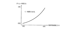
- a correspondence relationship between the oxygen storage capacity A and the delay time B is illustrated in FIG.
- the oxygen storage capacity A is low, the amount of oxygen desorbed from the catalysts 6 and 7 immediately after returning from the fuel cut decreases, so the exhaust purification performance does not deteriorate so much. Therefore, by setting the delay time B longer as the oxygen storage capacity A is higher, it is possible to efficiently suppress a decrease in exhaust purification performance due to desorbed oxygen.
- the delay time B may be set by using the oxygen storage capacities A U and A D of the respective catalysts 6 and 7 calculated by the calculation unit 3.
- the oxygen storage capacity AD of the rear catalyst 7 can be obtained by subtracting the oxygen storage capacity A U of the front catalyst 6 from the total oxygen storage capacity A.
- the first delay time B U corresponding to the oxygen storage capacity A U of the front catalyst 6 is set, and the second delay time B D corresponding to the oxygen storage capacity A D of the rear catalyst 7 is set.
- These added values can also be calculated as the delay time B.
- FIG. 4 is a flowchart illustrating a fuel cut control procedure. This flow is repeatedly performed at a predetermined cycle when, for example, the ignition key switch (main switch) of the vehicle is on.
- the symbol C in the flow is a counter value corresponding to the time during which the fuel cut condition continues to be established.
- the value C + 1 is substituted into the counter value C, and the elapsed time is measured (step A4).
- step A8 the control in this calculation cycle is completed.
- step A5 it is determined whether or not the elapsed time is equal to or longer than the delay time B (step A5). This determination can be replaced by determining whether or not the counter value C is equal to or greater than a predetermined value C 0 corresponding to the delay time B.
- step A9 it is determined whether or not the fuel cut end condition is satisfied.
- the fuel cut is continued (step A13).
- the delay time B setting flow is started (step A12)
- the control in the calculation cycle ends.
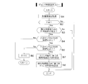
- FIG. 5 is a flowchart illustrating a procedure for setting the delay time B. This flow is started immediately after the fuel cut is completed, and is performed in parallel with the flow shown in FIG. 4 until the fuel cut is started again.
- the symbol T in the flow is a counter value corresponding to the output inversion time of the downstream sensor 17.
- step B4 whether the sensor output V of the upstream sensor 15 is the threshold value V 1 or more is determined.
- V ⁇ in case of V 1 completed control in the calculation cycle the flow proceeds to step B5 in the case of V ⁇ V 1.
- step B5 whether the sensor output V of the downstream sensor 17 is the threshold value V 1 or more is determined.
- the value T + 1 to the counter value T is substituted when a V ⁇ V 1, the elapsed time is measured (step B6).
- the oxygen storage capacity A of the catalyst 6, 7 is calculated by the calculating unit 3 (step B7).
- the setting unit 4 sets a delay time B based on the oxygen storage capacity A (step B8).
- the set delay time B is reflected in the determination content in step A5 in FIG. 4 (e.g., the value of the predetermined value C 0).
- a traveling state of a vehicle equipped with the engine control device 1 will be described with reference to FIGS. 6 (A) to 6 (E).
- Time t 10 the accelerator pedal is returned stepping in, the throttle opening is fully closed [FIG. 6 (B)], the engine rotational speed N gradually decreases [FIG 6 (D)], the vehicle speed S is reduced [FIG. 6 (E)].
- the fuel cut condition is satisfied.
- the fuel cut delay time B is not set, as shown by the broken line in FIG. 6A, outside air is introduced into the exhaust passage 13 to increase the air-fuel ratio, and the catalyst 6, A large amount of oxygen is stored in the oxygen storage material 7. Accordingly, as indicated by a broken line in FIG. 6 (C), the exhaust purification performance of the catalyst 6 is reduced immediately after the time t 13 where the fuel cut is finished, NOx exhaust concentration will temporarily increase.
- delay time B of the fuel cut is set delay time B of the fuel cut, the period from at least the time t 11 to time t 12 that the delay time B has elapsed, fuel cut is suspended without being started.
- the fuel cut execution period is shortened by the delay time B, and the amount of oxygen stored in the catalysts 6 and 7 is reduced. Therefore, as shown by a solid line in FIG. 6C, the exhaust purification performance of the catalysts 6 and 7 is improved as compared with the case where the delay time B is not set.
- the fuel cut-off condition at time t 16 is the same when satisfied, until the delay time B has elapsed, fuel cut is suspended without being started. Further, if the accelerator pedal is depressed during the delay time B and the throttle opening is increased, the fuel cut condition is not satisfied and the fuel cut is not started. If the fuel cut delay time B is not set, an instantaneous fuel cut that can be completed in less than a few seconds occurs as shown by the broken line in FIG. . Thus, as indicated by the broken line in FIG. 6 (C), the reduced exhaust gas purification performance after the time t 17 the throttle opening starts to increase, NOx exhaust concentration will temporarily increase. On the other hand, in this embodiment, such an instantaneous fuel cut is suppressed or prohibited. Thus, while suppressing the deterioration of fuel economy of the vehicle, the exhaust purification performance after the time t 17 can be maintained without lowering.
- the fuel cut delay time B is set based on the total oxygen storage capacity A of the catalyst 6 and the catalyst 7. Accordingly, the amount of time for performing the fuel cut can be determined in consideration of the amount of oxygen that can be desorbed from the catalysts 6 and 7 after the end of the fuel cut. Therefore, it is possible to accurately suppress the deterioration of the exhaust purification performance after returning from the fuel cut.
- the delay time B is extended as the oxygen storage capacity A is higher, and the delay time B is shortened as the oxygen storage capacity A is lower.
- This setting is derived from the fact that the higher the oxygen storage capacity A, the greater the amount of oxygen desorbed from the catalysts 6 and 7 when returning from the fuel cut, and the greater the adverse effect on the exhaust purification performance. That is, as the oxygen storage capacity A is higher, the delay time B is extended, so that the fuel cut can be made difficult to start, and the fuel cut execution time can be shortened. Therefore, the amount of oxygen desorbed from the catalysts 6 and 7 after returning from the fuel cut can be reduced, and the exhaust purification performance can be improved.
- the upstream sensor 15 disposed on the upstream side of the catalysts 6 and 7 and the downstream sensor 17 disposed on the downstream side are used.
- the oxygen storage capacity A is calculated.
- the response time difference here corresponds to the time from time t 1 to time t 3 (output inversion time) in FIG.
- the pre-stage catalyst 6 of the present embodiment has a larger amount of catalyst precious metal than the post-stage catalyst 7, the pre-stage catalyst 6 is larger than the post-stage catalyst 7 in terms of influence on the total exhaust purification performance.
- the engine control device 1 instead of referring to the total of oxygen storage capacity A of the catalyst 6 and the catalyst 7, it may be a case you want a oxygen storage capacity A U only precatalyst 6.
- the engine control device 1 using an intermediate sensor 16 that is disposed between the catalyst 6 and 7, it is possible to calculate the oxygen storage capacity A U of the pre-stage catalyst 6. That is, referring to the time (second output inversion time) from time t 1 to time t 2 in FIG.
- the oxygen storage capacity A U of the front catalyst 6 is lower as this time is shorter.
- the oxygen storage capacity A U of the front catalyst 6 may be calculated.
- the oxygen storage capacity AD of the rear catalyst 7 may be obtained by subtracting the oxygen storage capacity A U of the front catalyst 6 from the total oxygen storage capacity A.
- the calculation unit 3 that calculates the delay time B based on the oxygen storage capacity A of the catalysts 6 and 7 is exemplified, but it is also possible to calculate the delay time B in consideration of other parameters.
- the ease of adsorption of oxygen to the oxygen storage material can vary depending on the catalyst temperature, exhaust temperature, and ambient temperature (outside temperature). Therefore, the delay time B may be corrected in consideration of these various temperatures.
- the relationship between the oxygen storage capacity A and the delay time B is not limited to the relationship shown in FIG.
- the lower the oxygen storage capacity A the lower the exhaust purification performance of the catalysts 6 and 7. Therefore, by shortening the fuel cut execution time as much as possible, It may be possible to reduce the amount of oxygen released.
- the delay time B longer as the oxygen storage capacity A is lower, it is possible to suppress a decrease in exhaust purification performance due to desorbed oxygen.
- the oxygen storage capacity A is calculated based on the output reversal time when the air-fuel ratio is changed from lean to weakly rich (when returning from the fuel cut).
- the calculation method of A is not limited to this.
- the oxygen storage capacity A may be calculated based on the oscillation cycle (frequency) of the oxygen concentration detected on the downstream side of the catalysts 6 and 7 when the air-fuel ratio is vibrated near the stoichiometric range. This oscillation period becomes shorter as the oxygen storage capacity A of the catalysts 6 and 7 decreases.
- the vibration frequency on the downstream side of the catalysts 6 and 7 changes so as to approach the vibration frequency on the upstream side as the oxygen storage capacity A decreases. Therefore, the vibration period (frequency) of the oxygen concentration, the vibration frequency ratio in the upstream and downstream, and the like can be used as an index of the oxygen storage capacity A.
Landscapes
- Engineering & Computer Science (AREA)
- Chemical & Material Sciences (AREA)
- Combustion & Propulsion (AREA)
- Mechanical Engineering (AREA)
- General Engineering & Computer Science (AREA)
- Chemical Kinetics & Catalysis (AREA)
- Health & Medical Sciences (AREA)
- Toxicology (AREA)
- Materials Engineering (AREA)
- Electrical Control Of Air Or Fuel Supplied To Internal-Combustion Engine (AREA)
- Exhaust Gas After Treatment (AREA)
- Combined Controls Of Internal Combustion Engines (AREA)
Abstract
所定の燃料カット条件が成立した場合に、所定のディレイ時間(B)が経過した後にエンジン(10)への燃料供給を遮断する燃料カット制御部(2)を備える。また、エンジン(10)の排気系に介装された触媒(6、7)の酸素吸蔵能力を算出する算出部(3)を備える。さらに、算出部(3)で算出された酸素吸蔵能力に応じて、ディレイ時間(B)の長さを設定する設定部(4)を備える。
Description
本発明は、酸素吸蔵材を含む触媒がエンジンの排気系に介装された車両の排気浄化制御装置に関する。
従来、ガソリン車両の排気系に介装される触媒の一つとして、酸素吸蔵材を含む三元触媒が知られている。三元触媒とは、理論空燃比近傍の雰囲気下で窒素酸化物(NOx)の還元反応、炭化水素(HnCm)の酸化反応、一酸化炭素(CO)の酸化反応を同時に促進する触媒である。また、酸素吸蔵材とは、リーン雰囲気下で酸素を吸蔵し、リッチ雰囲気下において、リーン運転中に吸蔵した酸素を脱離させる特性を持った助触媒である。酸素吸蔵材の具体例としては、セリア(CeO2)、セリア・ジルコニア複合材料(CeO2-ZrO2)、アルミナ・セリア・ジルコニア複合材料(Al2O3-CeO2-ZrO2)、これらの材料に第2、第3の元素成分を複合した材料などが挙げられる。これらの酸素吸蔵材を触媒に含ませることで、触媒の活性サイト周囲の酸素濃度が理論空燃比近傍の濃度に維持されやすくなる。これにより、触媒活性が良好となる空燃比が確保され、触媒の排気浄化性能が向上する。なお、酸素吸蔵材に吸蔵された酸素は、炭化水素、一酸化炭素、水素の酸化反応に消費されうる(特許文献1参照)。
ところで、上記の触媒を排気系に備えたエンジンに対して、燃料カットと呼ばれる制御が実施されることがある。燃料カットとは、所定の燃料カット条件が成立したときに、エンジンへの燃料供給を一時的に停止する制御である。この制御は、例えば車両の惰性走行中や減速中に実施されて、無駄な燃料消費を抑制するように機能する。つまり、燃料カットを実施することで、車両の燃費を改善することができる。
しかしながら、燃料カットの実施中は排気系に外気が流入するため、触媒の酸素吸蔵材に吸蔵される酸素量が過剰となる場合がある。このような過剰な吸蔵酸素は、燃料カットからの復帰時における排気浄化性能を低下させうる。すなわち、エンジンが燃料カットから復帰したときに、酸素吸蔵材から脱離する酸素量が一時的に増加するため、空燃比がややリーン寄りとなり窒素酸化物の浄化率が低下しやすい。また、脱離する酸素量を考慮して触媒周囲の空燃比を理論空燃比にするためには、燃料噴射量を増加させなければならない。これにより、結果的にトータルの燃料噴射量が増加することになり、燃料カットによる燃費改善効果が相殺されうる。
なお、仮に燃料カットを全く実施しなければ、触媒に酸素が過剰に吸蔵されることが防止されるため、高い排気浄化性能を維持することが可能である。しかしこの場合、車両の惰性走行中や減速中に無駄な燃料が消費されることになり、燃費が低下する。したがって、燃料カットを完全に不実施とすることは、現実的な解決策ではない。一方、数秒未満で完了するような瞬間的な燃料カットは、燃費改善効果が比較的小さいにもかかわらず、排気浄化性能を大きく低下させるおそれがある。したがって、燃費改善効果を損なわずに排気浄化性能を向上させるには、上記のような瞬間的な燃料カットが発生しないようにエンジンを制御することが望ましい。
本件の目的の一つは、上記のような課題に鑑みて創案されたものであり、触媒の排気浄化性能の低下を抑制しつつ燃費を改善することができる排気浄化制御装置を提供することである。なお、この目的に限らず、後述する「発明を実施するための形態」に示す各構成から導き出される作用効果であって、従来の技術では得られない作用効果を奏することも、本件の他の目的として位置付けることができる。
(1)ここで開示する排気浄化制御装置は、所定の燃料カット条件が成立した場合に、所定のディレイ時間が経過した後にエンジンへの燃料供給を遮断する燃料カット制御部を備える。また、前記エンジンの排気系に介装された酸素吸蔵材を含む触媒の酸素吸蔵能力(例えば、酸素吸蔵能力を表す指標値)を算出する算出部を備える。さらに、前記算出部で算出された前記酸素吸蔵能力に応じて、前記ディレイ時間の長さを設定する設定部を備える。
前記酸素吸蔵能力は、前記触媒に吸蔵される酸素の重量を表すことが好ましい。例えば、前記触媒が新品であるときの前記酸素吸蔵能力が最も高く、前記触媒を長く使用するほど前記酸素吸蔵能力が低下する特性を持つものであることが好ましい。
前記酸素吸蔵能力は、前記触媒に吸蔵される酸素の重量を表すことが好ましい。例えば、前記触媒が新品であるときの前記酸素吸蔵能力が最も高く、前記触媒を長く使用するほど前記酸素吸蔵能力が低下する特性を持つものであることが好ましい。
(2)前記設定部は、前記酸素吸蔵能力が低いほど前記ディレイ時間を短縮することが好ましい。例えば、前記触媒が新品であるときの前記ディレイ時間が最も長く設定され、前記触媒を長く使用するほど前記ディレイ時間が短く設定されることが好ましい。
(3)前記触媒の上流側の酸素濃度を検出する上流センサと、前記触媒の下流側の酸素濃度を検出する下流センサとを備えることが好ましい。この場合、前記算出部は、空燃比の変化に対する前記上流センサの応答時刻から前記下流センサの応答時刻までの出力反転時間が短いほど、前記酸素吸蔵能力が低いものと判断することが好ましい。
(3)前記触媒の上流側の酸素濃度を検出する上流センサと、前記触媒の下流側の酸素濃度を検出する下流センサとを備えることが好ましい。この場合、前記算出部は、空燃比の変化に対する前記上流センサの応答時刻から前記下流センサの応答時刻までの出力反転時間が短いほど、前記酸素吸蔵能力が低いものと判断することが好ましい。
(4)前記触媒は、前記排気系の上流側に位置する前段触媒と下流側に位置する後段触媒とを有することが好ましい。また、前記前段触媒と前記後段触媒との間の酸素濃度を検出する中間センサを備えることが好ましい。この場合、前記算出部は、空燃比の変化に対する前記上流センサの応答時刻から前記中間センサの応答時刻までの第二出力反転時間が短いほど、前記酸素吸蔵能力が低いものと判断することが好ましい。
(5)前記算出部は、前記触媒の経年劣化度合いに基づいて前期酸素吸蔵能力を算出することが好ましい。例えば、前記触媒の使用時間(前記触媒が新品のときからの使用時間を累積した積算値)に基づいて前期酸素吸蔵能力を算出してもよい。
(5)前記算出部は、前記触媒の経年劣化度合いに基づいて前期酸素吸蔵能力を算出することが好ましい。例えば、前記触媒の使用時間(前記触媒が新品のときからの使用時間を累積した積算値)に基づいて前期酸素吸蔵能力を算出してもよい。
(6)前記算出部は、前記エンジンの運転状態が所定期間安定したとの条件が成立している場合に、前記酸素吸蔵能力を算出することが好ましい。換言すれば、「前記エンジンの運転状態が所定期間安定すること」が、前記酸素吸蔵能力を算出するための条件に含まれることが好ましい。
(7)前記算出部は、前記触媒の温度が所定の温度範囲内にあるとの条件が成立している場合に、前記酸素吸蔵能力を算出することが好ましい。換言すれば、「前記触媒の温度が所定の温度範囲内にあること」が、前記酸素吸蔵能力を算出するための条件に含まれることが好ましい。
(7)前記算出部は、前記触媒の温度が所定の温度範囲内にあるとの条件が成立している場合に、前記酸素吸蔵能力を算出することが好ましい。換言すれば、「前記触媒の温度が所定の温度範囲内にあること」が、前記酸素吸蔵能力を算出するための条件に含まれることが好ましい。
触媒の酸素吸蔵能力に応じて燃料カットのディレイ時間の長さを任意に設定することで、触媒吸蔵される酸素量を調節することができ、触媒の排気浄化性能の低下を抑制することができる。また、酸素の過剰な吸蔵を抑制することで、燃料カット復帰後に行うエンジンの燃焼空燃比のリッチ化を抑制することができ、燃費を改善することができる。
図面を参照して、実施形態としての排気浄化制御装置について説明する。排気浄化制御装置の最小構成は、以下に説明するエンジン制御装置1のみで実現可能であるが、エンジン制御装置1及び酸素濃度センサ15~17を含むシステム全体を排気浄化制御装置として実現することも可能である。なお、以下に示す実施形態はあくまでも例示に過ぎず、以下の実施形態で明示しない種々の変形や技術の適用を排除する意図はない。本実施形態の各構成は、それらの趣旨を逸脱しない範囲で種々変形して実施することができる。また、必要に応じて取捨選択することができ、あるいは適宜組み合わせることができる。
[1.装置構成]
図1は、車両に搭載されるエンジン10及びこれを制御するエンジン制御装置1を模式的に示す図である。このエンジン10は、吸気ポート8内に設けられたインジェクタ9からの燃料噴射を一時的に停止する燃料カット機能を備えている。また、エンジン10の吸気通路11にはスロットル弁12が介装される。一方、排気通路13には上流側から順に、過給機のタービン14、前段触媒6、後段触媒7が配置される。
図1は、車両に搭載されるエンジン10及びこれを制御するエンジン制御装置1を模式的に示す図である。このエンジン10は、吸気ポート8内に設けられたインジェクタ9からの燃料噴射を一時的に停止する燃料カット機能を備えている。また、エンジン10の吸気通路11にはスロットル弁12が介装される。一方、排気通路13には上流側から順に、過給機のタービン14、前段触媒6、後段触媒7が配置される。
前段触媒6、後段触媒7はともに三元触媒であり、理論空燃比近傍の雰囲気下で窒素酸化物、炭化水素、一酸化炭素を浄化する機能を持つ。また、これらの前段触媒6、後段触媒7には、セリア系材料、セリア・ジルコニア系材料、セリア・ジルコニア・アルミナ系複合材料などの酸素吸蔵材が担持される。酸素吸蔵材はリーン雰囲気下で酸素を吸蔵し、リッチ雰囲気下において、リーン運転中に吸蔵した酸素を脱離させる特性を持つ。なお、前段触媒6は後段触媒7よりも触媒に担持する貴金属量が多い。
排気通路13上には、排ガス中の酸素濃度を検出する酸素濃度センサ15~17が介装される。以下、前段触媒6の上流側に配置されたものを、上流センサ15とも呼ぶ。同様に、前段触媒6と後段触媒7との間に配置されたものを中間センサ16とも呼び、後段触媒7の下流側に配置されたものを下流センサ17とも呼ぶ。上流センサ15、中間センサ16、下流センサ17のそれぞれは、理論空燃比相当の酸素濃度を閾値として、センサ出力Vを二値的に変化させるスイッチング出力型のジルコニアO2センサである。ここでは、空燃比がリッチであるときのセンサ出力Vが所定値V0であり、空燃比がリーンであるときのセンサ出力Vがゼロであるものとする。なお、ジルコニアO2センサのセンサ出力Vは温度によって変化するため、センサ出力Vを排気温度に応じて補正する制御構成としてもよい。各酸素濃度センサ15~17からのセンサ出力Vは、エンジン制御装置1に伝達される。
図1に示すように、エンジン10には、エンジン回転速度N(エンジン回転数)を検出するエンジン回転数センサ18と、エンジン10の冷却水温Wを検出する水温センサ19とが設けられる。また、車両の任意の位置には、車速Sを検出する車速センサ20が設けられる。これらのセンサ18~20で検出されたエンジン回転速度N、冷却水温W、車速Sの情報は、エンジン制御装置1に伝達される。また、スロットル弁12の開度(スロットル開度)の情報も、エンジン制御装置1に伝達される。
エンジン制御装置1(排気浄化制御装置)は、エンジン10を総合的に制御するコンピュータであり、車載ネットワーク網の通信ラインに接続される。このエンジン制御装置1は、例えばCPU(Central Processing Unit)、MPU(Micro Processing Unit)などのマイクロプロセッサやROM(Read Only Memory)、RAM(Random Access Memory)、不揮発メモリなどを集積した電子デバイス(ECU、電子制御装置)として形成される。ここでいうプロセッサとは、例えば制御ユニット(制御回路)や演算ユニット(演算回路)、キャッシュメモリ(レジスタ)等を内蔵する処理装置(プロセッサ)である。また、ROM、RAM及び不揮発メモリは、プログラムや作業中のデータが格納されるメモリ装置である。エンジン制御装置1で実施される制御の内容は、ファームウェアやアプリケーションプログラムとしてROM、RAM、不揮発メモリ、リムーバブルメディア内に記録される。また、プログラムの実行時には、プログラムの内容がRAM内のメモリ空間内に展開され、プロセッサによって実行される。
[2.制御構成]
エンジン制御装置1は、触媒6、7の酸素吸蔵能力Aに応じて、エンジン10の燃料カットを制御する機能を持つ。ここでは、燃料カットの開始条件が成立したときに、直ちにインジェクタ9からの燃料供給が遮断されるのではなく、酸素吸蔵能力Aに応じて設定されるディレイ時間Bが経過した後に燃料供給が遮断される。つまり、燃料カットの開始条件が成立した時点を基準として、ディレイ時間Bが経過する前にその開始条件が不成立となった場合には、その燃料カットは不実施とされる。これにより、ディレイ時間Bよりも短時間の瞬間的な燃料カットが抑制される。
エンジン制御装置1は、触媒6、7の酸素吸蔵能力Aに応じて、エンジン10の燃料カットを制御する機能を持つ。ここでは、燃料カットの開始条件が成立したときに、直ちにインジェクタ9からの燃料供給が遮断されるのではなく、酸素吸蔵能力Aに応じて設定されるディレイ時間Bが経過した後に燃料供給が遮断される。つまり、燃料カットの開始条件が成立した時点を基準として、ディレイ時間Bが経過する前にその開始条件が不成立となった場合には、その燃料カットは不実施とされる。これにより、ディレイ時間Bよりも短時間の瞬間的な燃料カットが抑制される。
上記のような制御を実施するための要素として、エンジン制御装置1には燃料カット制御部2、算出部3、設定部4が設けられる。これらはエンジン制御装置1で実行されるプログラムの一部の機能を示すものであり、ソフトウェアで実現されるものとする。ただし、各機能の一部又は全部をハードウェア(電子制御回路)で実現してもよく、あるいはソフトウェアとハードウェアとを併用して実現してもよい。
[2-1.燃料カット制御部]
燃料カット制御部2は、エンジン10の燃料カットを司るものであり、所定の燃料カット条件の成否に応じて燃料カットを実施するものである。ここでは、燃料カット条件が成立した場合に、所定のディレイ時間Bが経過した後にエンジン10への燃料供給を遮断する制御が実施される。燃料カット条件は、例えば以下の全ての条件1~4が成立することである。これらの条件が成立したままディレイ時間Bが経過した場合に、燃料カットが開始される。また、燃料カットの実施中にいずれかの条件が不成立になると、燃料カットが終了する。なお、ディレイ時間Bの間にいずれかの条件が不成立になった場合には、燃料カットが不実施とされる。
燃料カット制御部2は、エンジン10の燃料カットを司るものであり、所定の燃料カット条件の成否に応じて燃料カットを実施するものである。ここでは、燃料カット条件が成立した場合に、所定のディレイ時間Bが経過した後にエンジン10への燃料供給を遮断する制御が実施される。燃料カット条件は、例えば以下の全ての条件1~4が成立することである。これらの条件が成立したままディレイ時間Bが経過した場合に、燃料カットが開始される。また、燃料カットの実施中にいずれかの条件が不成立になると、燃料カットが終了する。なお、ディレイ時間Bの間にいずれかの条件が不成立になった場合には、燃料カットが不実施とされる。
=燃料カット条件=
1.エンジン回転速度Nが第一速度N1以上、第二速度N2以下である(N1≦N≦N2)
2.スロットル開度が全閉状態(所定開度以下)である
3.車速Sが所定車速S1以上、所定車速S2以下である(S1≦S≦S2)
4.冷却水温Wが所定水温W1以上である(W1≦W)
1.エンジン回転速度Nが第一速度N1以上、第二速度N2以下である(N1≦N≦N2)
2.スロットル開度が全閉状態(所定開度以下)である
3.車速Sが所定車速S1以上、所定車速S2以下である(S1≦S≦S2)
4.冷却水温Wが所定水温W1以上である(W1≦W)
[2-2.算出部]
算出部3は、触媒6、7の酸素吸蔵能力Aを算出するものである。ここでいう酸素吸蔵能力Aとは、触媒6、7に吸蔵される酸素の重量を表す。酸素吸蔵能力Aは、触媒6、7が劣化するに連れて低下する特性を有する。例えば、触媒6、7が新品であるときの酸素吸蔵能力Aは最も高く、触媒6、7の使用時間が長くなるほど酸素吸蔵能力Aは低下する特性を持つ。
算出部3は、触媒6、7の酸素吸蔵能力Aを算出するものである。ここでいう酸素吸蔵能力Aとは、触媒6、7に吸蔵される酸素の重量を表す。酸素吸蔵能力Aは、触媒6、7が劣化するに連れて低下する特性を有する。例えば、触媒6、7が新品であるときの酸素吸蔵能力Aは最も高く、触媒6、7の使用時間が長くなるほど酸素吸蔵能力Aは低下する特性を持つ。
本実施形態の算出部3は、空燃比を変化させたときに各酸素濃度センサ15~17が出力するセンサ出力Vに基づいて、触媒6、7の酸素吸蔵能力Aを算出する。すなわち、上流センサ15の応答時刻を基準として、下流センサ17の応答時刻までの時間(出力反転時間)に応じた酸素吸蔵能力Aを算出する。ここで、上流センサ15の応答時刻から下流センサ17の応答時刻までの時間が短いほど、触媒6と触媒7の総合的な酸素吸蔵能力Aが低いものと判断され、低い値の酸素吸蔵能力Aが算出される。
また、前段触媒6のみの酸素吸蔵能力AUに関して、上流センサ15の応答時刻を基準として、中間センサ16の応答時刻までの時間(第二出力反転時間)が短いほど低く算出される。一方、後段触媒7のみの酸素吸蔵能力ADは、総合的な酸素吸蔵能力Aから前段触媒6のみの酸素吸蔵能力AUを減じた値として算出される。触媒6、7各々の上下流に酸素濃度センサ15~17を配置することで、触媒6、7各々の酸素吸蔵能力AU、ADが精度よく算出される。
ここで、図2(A)~図2(C)を用いて酸素吸蔵能力Aの算出手法を詳述する。
図2(A)に示すように、燃料カットの実施中には空燃比がリーンである。時刻t0に燃料カットが終了してエンジン10の燃焼が再開すると、空燃比がストイキ近傍(例えば弱リッチ程度に相当するフィードバック目標空燃比)に制御される。空燃比の変動は、各酸素濃度センサ15~17における酸素濃度の変化として検出される。上流センサ15は、他のセンサ16、17と比較してエンジン10に近い位置に設けられていることから、時刻t0の直後である時刻t1に所定値V0を出力する。これに対し、中間センサ16は、前段触媒6から脱離した酸素の影響を受けて、時刻t1よりもやや遅れた時刻t2に所定値V0を出力する。さらに、下流センサ17は、後段触媒7から脱離した酸素の影響も受けて、時刻t2よりもさらに遅れた時刻t3に所定値V0を出力する。各センサ15~17のセンサ出力Vの変化を図2(B)に示す。
図2(A)に示すように、燃料カットの実施中には空燃比がリーンである。時刻t0に燃料カットが終了してエンジン10の燃焼が再開すると、空燃比がストイキ近傍(例えば弱リッチ程度に相当するフィードバック目標空燃比)に制御される。空燃比の変動は、各酸素濃度センサ15~17における酸素濃度の変化として検出される。上流センサ15は、他のセンサ16、17と比較してエンジン10に近い位置に設けられていることから、時刻t0の直後である時刻t1に所定値V0を出力する。これに対し、中間センサ16は、前段触媒6から脱離した酸素の影響を受けて、時刻t1よりもやや遅れた時刻t2に所定値V0を出力する。さらに、下流センサ17は、後段触媒7から脱離した酸素の影響も受けて、時刻t2よりもさらに遅れた時刻t3に所定値V0を出力する。各センサ15~17のセンサ出力Vの変化を図2(B)に示す。
一方、触媒6、7が経時劣化して酸素吸蔵能力Aが低下すると、各触媒6、7に吸蔵される酸素量が減少することから、各触媒6、7からの脱離酸素量も減少する。これにより、図2(C)に示すように、中間センサ16の応答時刻t4は、劣化前の時刻t2よりも早い時刻となる。同様に、下流センサ17の応答時刻t5も、劣化前の時刻t3より早い時刻となる。したがって、時刻t1を基準として、中間センサ16、下流センサ17のセンサ出力Vが変化するまでの時間が短いほど、酸素吸蔵能力Aが低いものと判断することができる。なお、時刻t1が時刻t0とほぼ同時刻であるとみなせる場合には、時刻t0を基準とした出力反転時間に基づいて、酸素吸蔵能力Aの高低を判断してもよい。ここで算出された酸素吸蔵能力Aの情報は、設定部4に伝達される。
上記の説明では、時刻t0に空燃比をリーンからストイキ近傍まで変化させているが、センサ出力Vの変化は、空燃比をストイキ近傍からリーン側へと変化させた場合にも検出可能である。したがって、例えば燃料カットの開始直後におけるセンサ出力Vの変化を観察することで、酸素吸蔵能力Aを把握することも可能である。また、ストイキ近傍の空燃比における各センサ15~17のセンサ出力Vは、温度に応じて変化しうる。そこで、図2(B)、図2(C)中に示すように、所定値V0よりも小さい閾値V1を予め設定しておき、センサ出力Vが閾値V1以上になった時刻を応答時刻とみなしてもよい。
[2-3.設定部]
設定部4は、算出部3で算出された酸素吸蔵能力Aに応じて、ディレイ時間Bの長さを設定するものである。ここでは、ディレイ時間Bが、触媒6と触媒7が有する総合的な酸素吸蔵能力Aに応じて設定される。本実施形態では、触媒6と触媒7が有する総合的な酸素吸蔵能力Aが高いほどディレイ時間Bが長く、酸素吸蔵能力Aが低いほどディレイ時間Bが短く設定される。酸素吸蔵能力Aとディレイ時間Bとの対応関係を図3に例示する。
設定部4は、算出部3で算出された酸素吸蔵能力Aに応じて、ディレイ時間Bの長さを設定するものである。ここでは、ディレイ時間Bが、触媒6と触媒7が有する総合的な酸素吸蔵能力Aに応じて設定される。本実施形態では、触媒6と触媒7が有する総合的な酸素吸蔵能力Aが高いほどディレイ時間Bが長く、酸素吸蔵能力Aが低いほどディレイ時間Bが短く設定される。酸素吸蔵能力Aとディレイ時間Bとの対応関係を図3に例示する。
酸素吸蔵能力Aが高いほど、エンジン10が燃料カットから復帰したときに、触媒6、7から脱離する酸素量が増大し、排気浄化性能に与える悪影響が大きくなる。一方、酸素吸蔵能力Aが低ければ、燃料カットからの復帰直後に触媒6、7から脱離する酸素量が減少するため、排気浄化性能はそれほど低下しない。そこで、酸素吸蔵能力Aが高いほどディレイ時間Bを長く設定することで、脱離酸素による排気浄化性能の低下を効率的に抑制できる。
なお、算出部3で算出された各々の触媒6、7の酸素吸蔵能力AU、ADを用いてディレイ時間Bを設定してもよい。なお、後段触媒7の酸素吸蔵能力ADは、トータルの酸素吸蔵能力Aから前段触媒6の酸素吸蔵能力AUを減算して求めることができる。そして、この場合、前段触媒6の酸素吸蔵能力AUに対応する第一ディレイ時間BUを設定するとともに、後段触媒7の酸素吸蔵能力ADに対応する第二ディレイ時間BDを設定し、これらの加算値をディレイ時間Bとして算出することも可能である。各々の触媒6、7の酸素吸蔵能力AU、ADを考慮することで、各触媒6、7の劣化度合いに応じたより適切なディレイ時間Bが与えられることになり、総合的な排気浄化性能の低下が抑制される。
[3.フローチャート]
[3-1.燃料カット制御]
図4は、燃料カットの制御手順を例示するフローチャートである。このフローは、例えば車両のイグニッションキースイッチ(メインスイッチ)がオンの状態であるときに、所定周期で繰り返し実施される。このフロー中で使用される制御フラグFは、燃料カットの実施状態を表すものであり、燃料カットの実施中にF=1に設定される。また、フロー中の記号Cは、燃料カット条件が成立し続けている時間に相当するカウンタ値である。
[3-1.燃料カット制御]
図4は、燃料カットの制御手順を例示するフローチャートである。このフローは、例えば車両のイグニッションキースイッチ(メインスイッチ)がオンの状態であるときに、所定周期で繰り返し実施される。このフロー中で使用される制御フラグFは、燃料カットの実施状態を表すものであり、燃料カットの実施中にF=1に設定される。また、フロー中の記号Cは、燃料カット条件が成立し続けている時間に相当するカウンタ値である。
最初に、燃料カット条件の判定に用いられる各種情報が取得され(ステップA1)、制御フラグFがF=0であることを条件として(ステップA2)、燃料カットの開始条件が成立するか否かが判定される(ステップA3)。ここで、例えば上記の条件1~4の全てが成立する場合には、カウンタ値Cに値C+1が代入されて、経過時間が計測される(ステップA4)。一方、条件1~4のいずれかが成立しない場合には、カウンタ値CがC=0にリセットされ(ステップA8)、この演算周期での制御が終了する。
燃料カットの開始条件が成立し続けた場合、その経過時間がディレイ時間B以上であるか否かが判定される(ステップA5)。この判定は、カウンタ値Cが、ディレイ時間Bに相当する所定値C0以上であるか否かを判定することに代えることができる。この条件が成立すると、燃料カット制御部2にて燃料カットが開始され、エンジン10への燃料供給が遮断される(ステップA6)。また、制御フラグFがF=1に設定され(ステップA7)、その演算周期での制御が終了する。
制御フラグFがF=1となる燃料カットの実施中には、燃料カットの終了条件が成立するか否かが判定される(ステップA9)。ここで、例えば上記の条件1~4の全てが成立したままであれば、燃料カットが継続される(ステップA13)。一方、条件1~4のいずれかが不成立になると、燃料カットが終了する(ステップA10)。また、制御フラグFがF=0に設定されるとともに(ステップA11)、ディレイ時間Bの設定フローが開始され(ステップA12)、その演算周期での制御が終了する。
[3-2.ディレイ時間の設定]
図5は、ディレイ時間Bの設定手順を例示するフローチャートである。このフローは、燃料カットが終了した直後に開始され、燃料カットが再び開始されるまでの間に、図4に示すフローと並行して実施される。フロー中の記号Tは、下流センサ17の出力反転時間に相当するカウンタ値である。
図5は、ディレイ時間Bの設定手順を例示するフローチャートである。このフローは、燃料カットが終了した直後に開始され、燃料カットが再び開始されるまでの間に、図4に示すフローと並行して実施される。フロー中の記号Tは、下流センサ17の出力反転時間に相当するカウンタ値である。
まず、ディレイ時間Bの設定に用いられる各種情報が取得され(ステップB1)、制御フラグFがF=0であることを条件として(ステップB2)、車両の走行条件やエンジン10の運転条件が、触媒6、7の有する酸素吸蔵能力Aを精度よく計測できる条件となっているか否かが判定される(ステップB3)。例えば、車両の走行状態やエンジン10の運転状態が安定して連続しているか否かが判定される。また、酸素吸蔵能力Aの算出精度は触媒温度の影響を強く受けて変化するため、触媒温度が指定温度範囲内(例えば、400℃~600℃)であるか否かが判定される。これらの条件が成立する場合には、酸素吸蔵能力Aを精度よく計測できる状態であると判断されて、ステップB4に進む。一方、本フローと並行して実施される図4のフローで制御フラグFがF=1に設定された場合や、ステップB3の条件が不成立の場合には、本フローは終了する。
ステップB4では、上流センサ15のセンサ出力Vが閾値V1以上であるか否かが判定される。ここで、V<V1である場合にはこの演算周期での制御が終了し、V≧V1である場合にはステップB5に進む。ステップB5では、下流センサ17のセンサ出力Vが閾値V1以上であるか否かが判定される。ここで、V<V1である場合にはカウンタ値Tに値T+1が代入されて、経過時間が計測される(ステップB6)。一方、V≧V1になると、その時点におけるカウンタ値Tに基づき、算出部3で触媒6、7の酸素吸蔵能力Aが算出される(ステップB7)。また、設定部4では、酸素吸蔵能力Aに基づいてディレイ時間Bが設定される(ステップB8)。ここで設定されたディレイ時間Bは、図4中のステップA5での判定内容(例えば、所定値C0の値)に反映される。
[4.作用]
上記のエンジン制御装置1を搭載した車両の走行状態について、図6(A)~図6(E)を用いて説明する。時刻t10にアクセルペダルが踏み戻され、スロットル開度が全閉になると〔図6(B)〕、エンジン回転速度Nが徐々に低下するとともに〔図6(D)〕、車速Sが減少する〔図6(E)〕。その後、時刻t11にエンジン回転速度Nが第二速度N2以下になると、燃料カット条件が成立する。ここで仮に、燃料カットのディレイ時間Bが設定されなかった場合には、図6(A)中に破線で示すように、排気通路13に外気が導入されて空燃比が増大し、触媒6、7の酸素吸蔵材に多量の酸素が吸蔵されることになる。したがって、図6(C)に破線で示すように、燃料カットが終了した時刻t13の直後から触媒6、7の排気浄化性能が低下し、NOx排出濃度が一時的に上昇してしまう。
上記のエンジン制御装置1を搭載した車両の走行状態について、図6(A)~図6(E)を用いて説明する。時刻t10にアクセルペダルが踏み戻され、スロットル開度が全閉になると〔図6(B)〕、エンジン回転速度Nが徐々に低下するとともに〔図6(D)〕、車速Sが減少する〔図6(E)〕。その後、時刻t11にエンジン回転速度Nが第二速度N2以下になると、燃料カット条件が成立する。ここで仮に、燃料カットのディレイ時間Bが設定されなかった場合には、図6(A)中に破線で示すように、排気通路13に外気が導入されて空燃比が増大し、触媒6、7の酸素吸蔵材に多量の酸素が吸蔵されることになる。したがって、図6(C)に破線で示すように、燃料カットが終了した時刻t13の直後から触媒6、7の排気浄化性能が低下し、NOx排出濃度が一時的に上昇してしまう。
これに対し、本実施形態では燃料カットのディレイ時間Bが設定され、少なくとも時刻t11からディレイ時間Bが経過した時刻t12までの間は、燃料カットが開始されずに保留される。これにより、図6(A)に示すように、ディレイ時間Bの分だけ燃料カットの実施期間が短縮されることになり、触媒6、7に吸蔵される酸素量が減少する。したがって、図6(C)に実線で示すように、ディレイ時間Bが設定されなかった場合と比較して、触媒6、7の排気浄化性能が向上する。
その後、時刻t16に再び燃料カット条件が成立した場合も同様であり、ディレイ時間Bが経過するまでの間は、燃料カットが開始されずに保留される。また、ディレイ時間Bの間にアクセルペダルが踏み込まれてスロットル開度が大きくなると、燃料カット条件が不成立となり、燃料カットが開始されない。ここで仮に、燃料カットのディレイ時間Bが設定されなかった場合には、図6(A)中に破線で示すように、数秒未満で完了するような瞬間的な燃料カットが発生することになる。これにより、図6(C)中に破線で示すように、スロットル開度が増大し始める時刻t17以降の排気浄化性能が低下し、NOx排出濃度が一時的に上昇してしまう。一方、本実施形態では、このような瞬間的な燃料カットが抑制、禁止される。したがって、車両の燃費悪化を抑制しつつ、時刻t17以降の排気浄化性能を低下させることなく維持することができる。
[5.効果]
(1)上記のエンジン制御装置1(排気浄化制御装置)では、燃料カット条件が成立した場合に、エンジン10への燃料供給を停止させるためのディレイ時間Bが設定されるため、瞬間的な燃料カットの発生を防止することができる。また、触媒6、7に酸素が吸蔵される機会を減少させることができるとともに、燃料カットの実施時間を短縮することができる。これにより、触媒6、7に吸蔵される酸素量を減少させることができ、燃料カットからの復帰後における排気浄化性能の低下を抑制することができる。また、ディレイ時間Bが経過した後には燃料カットが実施されるため、無駄な燃料消費を抑制することができ、燃費を改善することができる。したがって、触媒6、7の排気浄化性能の低下を抑制しつつ燃費を改善することができる。
(1)上記のエンジン制御装置1(排気浄化制御装置)では、燃料カット条件が成立した場合に、エンジン10への燃料供給を停止させるためのディレイ時間Bが設定されるため、瞬間的な燃料カットの発生を防止することができる。また、触媒6、7に酸素が吸蔵される機会を減少させることができるとともに、燃料カットの実施時間を短縮することができる。これにより、触媒6、7に吸蔵される酸素量を減少させることができ、燃料カットからの復帰後における排気浄化性能の低下を抑制することができる。また、ディレイ時間Bが経過した後には燃料カットが実施されるため、無駄な燃料消費を抑制することができ、燃費を改善することができる。したがって、触媒6、7の排気浄化性能の低下を抑制しつつ燃費を改善することができる。
また、上記のエンジン制御装置1では、触媒6と触媒7のトータルの酸素吸蔵能力Aに基づいて燃料カットのディレイ時間Bが設定される。これにより、燃料カットの終了後に触媒6、7から脱離しうる酸素量を考慮して、燃料カットを実施する時間の短縮量を決定することができる。したがって、燃料カットからの復帰後における排気浄化性能の低下を精度よく抑制することができる。
(2)上記のエンジン制御装置1では、例えば図3に示すように、酸素吸蔵能力Aが高いほどディレイ時間Bが延長され、酸素吸蔵能力Aが低いほどディレイ時間Bが短縮される。この設定は、酸素吸蔵能力Aが高いほど、燃料カットから復帰したときに触媒6、7から脱離する酸素量が増大し、排気浄化性能に与える悪影響が大きくなることに由来する。つまり、酸素吸蔵能力Aが高いほどディレイ時間Bを延長することで、燃料カットを開始されにくくすることができ、かつ、燃料カットの実施時間を短縮することができる。したがって、燃料カットからの復帰後に触媒6、7から脱離する酸素量を減少させることができ、排気浄化性能を向上させることができる。
(3)上記のエンジン制御装置1では、触媒6、7の上流側に配置された上流センサ15と下流側に配置された下流センサ17とを用いて、空燃比の変化に対する応答時刻差に基づいて酸素吸蔵能力Aを算出している。ここでいう応答時刻差とは、図2(B)中の時刻t1から時刻t3までの時間(出力反転時間)に相当する。この応答時刻差が短いほど酸素吸蔵能力Aが低いものと判断することで、触媒6と触媒7のトータルの酸素吸蔵能力Aを精度よく把握することができ、適切にディレイ時間Bを設定することができる。したがって、排気浄化性能を向上させることができる。
(4)本実施形態の前段触媒6は、後段触媒7よりも触媒貴金属の担持量が多いため、トータルの排気浄化性能に与える影響についても、後段触媒7よりも前段触媒6の方が大きい。これを踏まえて、触媒6と触媒7のトータルの酸素吸蔵能力Aを参照する代わりに、前段触媒6のみの酸素吸蔵能力AUを参照したい場合も考えられる。このような要望に対し、上記のエンジン制御装置1では、触媒6、7の間に配置された中間センサ16を用いて、前段触媒6の酸素吸蔵能力AUを算出することが可能である。すなわち、図2(B)中の時刻t1から時刻t2までの時間(第二出力反転時間)を参照し、この時間が短いほど前段触媒6の酸素吸蔵能力AUが低いものと判断して、前段触媒6の酸素吸蔵能力AUを算出すればよい。また、後段触媒7の酸素吸蔵能力ADは、トータルの酸素吸蔵能力Aから前段触媒6の酸素吸蔵能力AUを減算して求めればよい。このように、個々の酸素吸蔵能力AU、ADを用いることで、燃料カットのディレイ時間Bを適正化することができ、排気浄化性能を向上させることができる。
[6.変形例]
上述の実施形態では、排気通路13に二つの触媒6、7が介装された排気系を例示したが、具体的な触媒6、7の個数やレイアウトはこれに限定されない。また、触媒6、7の種類に関しても同様であり、三元触媒だけでなく、三元機能を有するNOx吸蔵還元触媒やNOx選択還元触媒などの触媒を対象とすることができる。なお、触媒6、7に含有される酸素吸蔵材の種類についても同様である。
上述の実施形態では、排気通路13に二つの触媒6、7が介装された排気系を例示したが、具体的な触媒6、7の個数やレイアウトはこれに限定されない。また、触媒6、7の種類に関しても同様であり、三元触媒だけでなく、三元機能を有するNOx吸蔵還元触媒やNOx選択還元触媒などの触媒を対象とすることができる。なお、触媒6、7に含有される酸素吸蔵材の種類についても同様である。
上述の実施形態では、触媒6、7の酸素吸蔵能力Aに基づいてディレイ時間Bを算出する算出部3を例示したが、他のパラメータを考慮してディレイ時間Bを算出することも考えられる。酸素吸蔵材への酸素の吸着しやすさは、触媒温度や排気温度、雰囲気温度(外気温)に依存して変化しうる。そこで、これらの各種温度を考慮してディレイ時間Bを補正してもよい。
また、酸素吸蔵能力Aとディレイ時間Bとの関係は、図3に示すような関係に限定されない。例えば、酸素吸蔵能力Aが低いほど触媒6、7の排気浄化性能が低下しているものと推定されることから、できるだけ燃料カットの実施時間を短縮することで、燃料カットからの復帰後における脱離酸素量を減少させたいことも考えられる。この場合、酸素吸蔵能力Aが低いほどディレイ時間Bを長く設定することで、脱離酸素による排気浄化性能の低下を抑制することができる。
上述の実施形態では4つの燃料カット条件を例示したが、具体的な燃料カット条件は任意に設定可能であり、各条件の組み合わせについても任意に設定可能である。また、車両走行中の燃料カットだけでなく、車両停止中の燃料カット(アイドリングストップ制御)に対して、上記の制御を適用することも可能である。少なくとも、瞬間的な燃料カットの発生を抑制することで、上述の実施形態と同様の効果を奏するものとなる。
また、上述の実施形態では、空燃比をリーンから弱リッチへと変化させたとき(燃料カットから復帰したとき)の出力反転時間に基づいて酸素吸蔵能力Aを算出しているが、酸素吸蔵能力Aの算出手法はこれに限定されない。例えば、空燃比をストイキ近傍で振動させたときに、触媒6、7の下流側にて検出される酸素濃度の振動周期(周波数)に基づき、酸素吸蔵能力Aを算出してもよい。この振動周期は、触媒6、7の酸素吸蔵能力Aが低下するに連れて短くなる。また、触媒6、7の下流側における振動周波数は、酸素吸蔵能力Aが低下するに連れて、上流側における振動周波数に近づくように変化する。したがって、酸素濃度の振動周期(周波数)や上下流における振動周波数比などを酸素吸蔵能力Aの指標として用いることができる。
1 エンジン制御装置
2 燃料カット制御部
3 算出部
4 設定部
6 前段触媒
7 後段触媒
10 エンジン
15 上流センサ(上流O2センサ)
16 中間センサ(中間O2センサ)
17 下流センサ(下流O2センサ)
18 エンジン回転数センサ
19 水温センサ
20 車速センサ
A 酸素吸蔵能力
B ディレイ時間
2 燃料カット制御部
3 算出部
4 設定部
6 前段触媒
7 後段触媒
10 エンジン
15 上流センサ(上流O2センサ)
16 中間センサ(中間O2センサ)
17 下流センサ(下流O2センサ)
18 エンジン回転数センサ
19 水温センサ
20 車速センサ
A 酸素吸蔵能力
B ディレイ時間
Claims (7)
- 所定の燃料カット条件が成立した場合に、所定のディレイ時間が経過した後にエンジンへの燃料供給を遮断する燃料カット制御部と、
前記エンジンの排気系に介装された酸素吸蔵材を含む触媒の酸素吸蔵能力を算出する算出部と、
前記算出部で算出された前記酸素吸蔵能力に応じて、前記ディレイ時間の長さを設定する設定部と、
を備えたことを特徴とする、排気浄化制御装置。 - 前記設定部は、前記酸素吸蔵能力が低いほど前記ディレイ時間を短縮する
ことを特徴とする、請求項1記載の排気浄化制御装置。 - 前記触媒の上流側の酸素濃度を検出する上流センサと、
前記触媒の下流側の酸素濃度を検出する下流センサとを備え、
前記算出部は、空燃比の変化に対する前記上流センサの応答時刻から前記下流センサの応答時刻までの出力反転時間が短いほど、前記酸素吸蔵能力が低いものと判断する
ことを特徴とする、請求項1又は2記載の排気浄化制御装置。 - 前記触媒が、前記排気系の上流側に位置する前段触媒と下流側に位置する後段触媒とを有するとともに、
前記前段触媒と前記後段触媒との間の酸素濃度を検出する中間センサを備え、
前記算出部は、空燃比の変化に対する前記上流センサの応答時刻から前記中間センサの応答時刻までの第二出力反転時間が短いほど、前記酸素吸蔵能力が低いものと判断する
ことを特徴とする、請求項3記載の排気浄化制御装置。 - 前記算出部は、前記触媒の経年劣化度合いに基づいて前期酸素吸蔵能力を算出する
ことを特徴とする、請求項1又は2記載の排気浄化制御装置。 - 前記算出部は、前記エンジンの運転状態が所定期間安定したとの条件が成立している場合に、前記酸素吸蔵能力を算出する
ことを特徴とする、請求項1~5の何れか1項に記載の排気浄化制御装置。 - 前記算出部は、前記触媒の温度が所定の温度範囲内にあるとの条件が成立している場合に、前記酸素吸蔵能力を算出する
ことを特徴とする、請求項1~6の何れか1項に記載の排気浄化制御装置。
Priority Applications (2)
| Application Number | Priority Date | Filing Date | Title |
|---|---|---|---|
| EP16845983.2A EP3351780B1 (en) | 2015-09-16 | 2016-02-02 | Exhaust purification control device |
| US15/757,736 US10526988B2 (en) | 2015-09-16 | 2016-02-02 | Controlling device for purifying exhaust gas purifying |
Applications Claiming Priority (2)
| Application Number | Priority Date | Filing Date | Title |
|---|---|---|---|
| JP2015-182547 | 2015-09-16 | ||
| JP2015182547A JP6597101B2 (ja) | 2015-09-16 | 2015-09-16 | 排気浄化制御装置 |
Publications (1)
| Publication Number | Publication Date |
|---|---|
| WO2017047109A1 true WO2017047109A1 (ja) | 2017-03-23 |
Family
ID=58288638
Family Applications (1)
| Application Number | Title | Priority Date | Filing Date |
|---|---|---|---|
| PCT/JP2016/053031 WO2017047109A1 (ja) | 2015-09-16 | 2016-02-02 | 排気浄化制御装置 |
Country Status (4)
| Country | Link |
|---|---|
| US (1) | US10526988B2 (ja) |
| EP (1) | EP3351780B1 (ja) |
| JP (1) | JP6597101B2 (ja) |
| WO (1) | WO2017047109A1 (ja) |
Families Citing this family (6)
| Publication number | Priority date | Publication date | Assignee | Title |
|---|---|---|---|---|
| DE102016123426A1 (de) * | 2016-12-05 | 2018-06-07 | Volkswagen Aktiengesellschaft | Verfahren und Abgasanlage zur Prüfung eines Beladungszustands eines Partikelfilters |
| DE102018119010A1 (de) * | 2018-08-06 | 2020-02-06 | Volkswagen Aktiengesellschaft | Verfahren und Vorrichtung zur Abgasnachbehandlung eines Verbrennungsmotors |
| JP7077883B2 (ja) | 2018-09-06 | 2022-05-31 | トヨタ自動車株式会社 | 内燃機関の排気浄化装置 |
| KR102654452B1 (ko) | 2019-02-21 | 2024-04-03 | 현대자동차 주식회사 | 자동차의 배기가스 정화장치 및 그 제어방법 |
| FR3134149A1 (fr) * | 2022-03-29 | 2023-10-06 | Renault S.A.S | Système d’injection configuré pour la stabilisation de la valeur de la richesse d’un mélange air-carburant en fonction de la capacité de stockage en oxygène courante d’un catalyseur |
| CN118049302B (zh) * | 2024-04-16 | 2024-06-28 | 江苏创泰特钢制品有限公司 | 一种汽车尾气净化装置 |
Citations (3)
| Publication number | Priority date | Publication date | Assignee | Title |
|---|---|---|---|---|
| JP2011106352A (ja) * | 2009-11-18 | 2011-06-02 | Nissan Motor Co Ltd | 内燃機関の燃料噴射制御装置 |
| JP2014181623A (ja) * | 2013-03-19 | 2014-09-29 | Hitachi Automotive Systems Ltd | 内燃機関の制御装置 |
| JP2015010489A (ja) * | 2013-06-27 | 2015-01-19 | ダイハツ工業株式会社 | 内燃機関の制御装置 |
Family Cites Families (13)
| Publication number | Priority date | Publication date | Assignee | Title |
|---|---|---|---|---|
| JPS58110805A (ja) * | 1981-12-24 | 1983-07-01 | Honda Motor Co Ltd | 自動二輪車用内燃機関における二次空気供給およびスロツトルオプナの作動制御装置 |
| US6667018B2 (en) * | 1994-07-05 | 2003-12-23 | Ngk Insulators, Ltd. | Catalyst-adsorbent for purification of exhaust gases and method for purification of exhaust gases |
| JP3966014B2 (ja) * | 2002-02-25 | 2007-08-29 | 株式会社デンソー | 内燃機関の排気浄化装置 |
| JP2005248781A (ja) * | 2004-03-03 | 2005-09-15 | Toyota Motor Corp | 内燃機関の燃料カット制御装置 |
| JP4671130B2 (ja) | 2006-07-21 | 2011-04-13 | トヨタ自動車株式会社 | 内燃機関の触媒劣化検出装置 |
| FR2905371B1 (fr) * | 2006-08-31 | 2010-11-05 | Rhodia Recherches & Tech | Composition a reductibilite elevee a base d'un oxyde de cerium nanometrique sur un support, procede de preparation et utilisation comme catalyseur |
| JP2010084750A (ja) * | 2008-09-04 | 2010-04-15 | Denso Corp | 排気浄化用触媒の劣化診断装置 |
| CN102470363B (zh) * | 2009-07-24 | 2015-01-28 | 株式会社科特拉 | 废气净化用催化剂 |
| JP5029718B2 (ja) * | 2010-03-18 | 2012-09-19 | トヨタ自動車株式会社 | 内燃機関の排気浄化装置 |
| US8826642B2 (en) * | 2010-04-13 | 2014-09-09 | Toyota Jidosha Kabushiki Kaisha | Device for purifying exhaust gas of internal combustion engine |
| JP5796635B2 (ja) * | 2011-11-28 | 2015-10-21 | 日産自動車株式会社 | 内燃機関の燃料カット制御装置及び燃料カット制御方法 |
| JP5642107B2 (ja) * | 2012-03-30 | 2014-12-17 | 本田技研工業株式会社 | 鞍乗型車両用排気ガス浄化装置及びそれに用いるパラジウム単層触媒 |
| JP2015071985A (ja) * | 2013-10-03 | 2015-04-16 | トヨタ自動車株式会社 | 内燃機関の制御装置 |
-
2015
- 2015-09-16 JP JP2015182547A patent/JP6597101B2/ja active Active
-
2016
- 2016-02-02 WO PCT/JP2016/053031 patent/WO2017047109A1/ja unknown
- 2016-02-02 US US15/757,736 patent/US10526988B2/en active Active
- 2016-02-02 EP EP16845983.2A patent/EP3351780B1/en active Active
Patent Citations (3)
| Publication number | Priority date | Publication date | Assignee | Title |
|---|---|---|---|---|
| JP2011106352A (ja) * | 2009-11-18 | 2011-06-02 | Nissan Motor Co Ltd | 内燃機関の燃料噴射制御装置 |
| JP2014181623A (ja) * | 2013-03-19 | 2014-09-29 | Hitachi Automotive Systems Ltd | 内燃機関の制御装置 |
| JP2015010489A (ja) * | 2013-06-27 | 2015-01-19 | ダイハツ工業株式会社 | 内燃機関の制御装置 |
Also Published As
| Publication number | Publication date |
|---|---|
| EP3351780B1 (en) | 2020-08-26 |
| JP2017057777A (ja) | 2017-03-23 |
| JP6597101B2 (ja) | 2019-10-30 |
| EP3351780A4 (en) | 2019-03-20 |
| US20180347492A1 (en) | 2018-12-06 |
| US10526988B2 (en) | 2020-01-07 |
| EP3351780A1 (en) | 2018-07-25 |
Similar Documents
| Publication | Publication Date | Title |
|---|---|---|
| JP6597101B2 (ja) | 排気浄化制御装置 | |
| JP5029718B2 (ja) | 内燃機関の排気浄化装置 | |
| JP6256240B2 (ja) | 内燃機関の制御装置 | |
| US10598063B2 (en) | Exhaust purification system of internal combustion engine | |
| JP2000345830A (ja) | 内燃機関の排気浄化装置 | |
| JP5338974B2 (ja) | 内燃機関の排気浄化装置 | |
| JP2017031946A (ja) | 内燃機関 | |
| JP2018178762A (ja) | 内燃機関の排気浄化装置 | |
| JP6056726B2 (ja) | 内燃機関の制御装置 | |
| JP6248978B2 (ja) | 内燃機関の制御装置 | |
| JP2007239698A (ja) | 内燃機関の空燃比制御装置 | |
| KR20180068164A (ko) | 배기가스 정화장치 및 그 제어 방법 | |
| JP4938532B2 (ja) | 内燃機関の空燃比制御装置 | |
| JP2017115621A (ja) | 排気浄化装置 | |
| JP2015121118A (ja) | 内燃機関の排気浄化装置 | |
| JP4366976B2 (ja) | 排気ガスセンサの異常検出装置 | |
| JP6613750B2 (ja) | 排気浄化制御装置 | |
| JP6244626B2 (ja) | ディーゼルエンジンの排気後処理装置 | |
| US11193408B2 (en) | Reactivation control apparatus and method | |
| JP2007092609A (ja) | 内燃機関の制御装置 | |
| JP6380264B2 (ja) | 酸素センサの異常診断装置 | |
| JP2019065797A (ja) | 内燃機関の排気浄化装置 | |
| JP2004232576A (ja) | 内燃機関の排気浄化装置 | |
| JP2004060613A (ja) | 内燃機関の空燃比制御装置 | |
| JP2004285841A (ja) | 内燃機関の排気浄化装置 |
Legal Events
| Date | Code | Title | Description |
|---|---|---|---|
| 121 | Ep: the epo has been informed by wipo that ep was designated in this application |
Ref document number: 16845983 Country of ref document: EP Kind code of ref document: A1 |
|
| NENP | Non-entry into the national phase |
Ref country code: DE |