WO2017043213A1 - パワーステアリング装置の制御装置及びパワーステアリング装置 - Google Patents
パワーステアリング装置の制御装置及びパワーステアリング装置 Download PDFInfo
- Publication number
- WO2017043213A1 WO2017043213A1 PCT/JP2016/072288 JP2016072288W WO2017043213A1 WO 2017043213 A1 WO2017043213 A1 WO 2017043213A1 JP 2016072288 W JP2016072288 W JP 2016072288W WO 2017043213 A1 WO2017043213 A1 WO 2017043213A1
- Authority
- WO
- WIPO (PCT)
- Prior art keywords
- motor
- phase
- electric motor
- real axis
- control
- Prior art date
- Legal status (The legal status is an assumption and is not a legal conclusion. Google has not performed a legal analysis and makes no representation as to the accuracy of the status listed.)
- Ceased
Links
Images


Classifications
-
- B—PERFORMING OPERATIONS; TRANSPORTING
- B62—LAND VEHICLES FOR TRAVELLING OTHERWISE THAN ON RAILS
- B62D—MOTOR VEHICLES; TRAILERS
- B62D5/00—Power-assisted or power-driven steering
- B62D5/04—Power-assisted or power-driven steering electrical, e.g. using an electric servo-motor connected to, or forming part of, the steering gear
- B62D5/0457—Power-assisted or power-driven steering electrical, e.g. using an electric servo-motor connected to, or forming part of, the steering gear characterised by control features of the drive means as such
- B62D5/0481—Power-assisted or power-driven steering electrical, e.g. using an electric servo-motor connected to, or forming part of, the steering gear characterised by control features of the drive means as such monitoring the steering system, e.g. failures
- B62D5/049—Power-assisted or power-driven steering electrical, e.g. using an electric servo-motor connected to, or forming part of, the steering gear characterised by control features of the drive means as such monitoring the steering system, e.g. failures detecting sensor failures
-
- B—PERFORMING OPERATIONS; TRANSPORTING
- B62—LAND VEHICLES FOR TRAVELLING OTHERWISE THAN ON RAILS
- B62D—MOTOR VEHICLES; TRAILERS
- B62D5/00—Power-assisted or power-driven steering
- B62D5/04—Power-assisted or power-driven steering electrical, e.g. using an electric servo-motor connected to, or forming part of, the steering gear
- B62D5/0457—Power-assisted or power-driven steering electrical, e.g. using an electric servo-motor connected to, or forming part of, the steering gear characterised by control features of the drive means as such
- B62D5/046—Controlling the motor
- B62D5/0463—Controlling the motor calculating assisting torque from the motor based on driver input
-
- H—ELECTRICITY
- H02—GENERATION; CONVERSION OR DISTRIBUTION OF ELECTRIC POWER
- H02P—CONTROL OR REGULATION OF ELECTRIC MOTORS, ELECTRIC GENERATORS OR DYNAMO-ELECTRIC CONVERTERS; CONTROLLING TRANSFORMERS, REACTORS OR CHOKE COILS
- H02P29/00—Arrangements for regulating or controlling electric motors, appropriate for both AC and DC motors
- H02P29/02—Providing protection against overload without automatic interruption of supply
- H02P29/032—Preventing damage to the motor, e.g. setting individual current limits for different drive conditions
-
- H—ELECTRICITY
- H02—GENERATION; CONVERSION OR DISTRIBUTION OF ELECTRIC POWER
- H02P—CONTROL OR REGULATION OF ELECTRIC MOTORS, ELECTRIC GENERATORS OR DYNAMO-ELECTRIC CONVERTERS; CONTROLLING TRANSFORMERS, REACTORS OR CHOKE COILS
- H02P6/00—Arrangements for controlling synchronous motors or other dynamo-electric motors using electronic commutation dependent on the rotor position; Electronic commutators therefor
- H02P6/14—Electronic commutators
- H02P6/16—Circuit arrangements for detecting position
-
- B—PERFORMING OPERATIONS; TRANSPORTING
- B60—VEHICLES IN GENERAL
- B60Y—INDEXING SCHEME RELATING TO ASPECTS CROSS-CUTTING VEHICLE TECHNOLOGY
- B60Y2400/00—Special features of vehicle units
- B60Y2400/30—Sensors
- B60Y2400/301—Sensors for position or displacement
Definitions
- the present invention relates to a control device and a power steering device for a power steering device applied to a vehicle.
- Patent Document 1 As a control device of a conventional power steering device, one described in Patent Document 1 below is known.
- the control device detects a steering mechanism that transmits the rotation of the steering wheel to the steered wheels, an electric motor that applies a steering assist force to the steering mechanism, and a real axis phase that is a rotational position of a rotor of the electric motor. And a control phase estimated based on a resistance and inductance of a winding of the electric motor, a current detection value, a voltage command value, and a steering speed, and the real axis phase.
- the driving efficiency of the electric motor is improved by detecting the phase difference and correcting the phase difference.
- the present invention has been devised in view of the technical problems described above, and an object thereof is to provide a control device for a power steering device and a power steering device capable of detecting an abnormality of a motor rotational position sensor.
- the present invention is provided with a steering mechanism that transmits rotation of a steering wheel to a steered wheel, an electric motor that applies a steering assist force to the steering mechanism, and the electric motor that is provided between the steering mechanism and the electric motor.
- a control device for a power steering apparatus comprising: a transmission mechanism that transmits the rotational force of the motor to a steering mechanism; and a motor rotational position sensor that detects a real axis phase that is a rotational position of a rotor of the electric motor, A control phase estimation unit that estimates a control phase that is a phase of an induced voltage generated in the electric motor based on a signal of a current value flowing through the electric motor, and the motor rotational position based on a difference between the real axis phase and the control phase.
- a sensor abnormality determination unit that determines whether or not the sensor is abnormal.
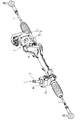
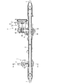
- FIG. 1 is a perspective view showing a power steering device according to a first embodiment of the present invention. It is a longitudinal cross-sectional view of the same power steering apparatus.
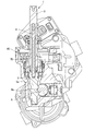
- FIG. 3 is a sectional view taken along line AA in FIG. 2.
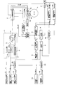
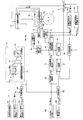
- It is a block diagram which shows the structure of the electric system which concerns on the control apparatus of this embodiment.
- It is a control block diagram which shows the arithmetic circuit structure of the control apparatus which concerns on this embodiment.
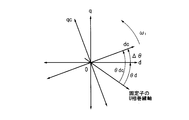
- It is a figure which shows the relationship between a real-axis phase and a control phase, and the definition of a phase difference.
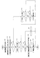
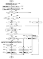
- It is a flowchart which shows abnormality determination process control of the motor rotation position sensor in 1st Embodiment.
- the power steering device includes a steering mechanism 1 that transmits the rotation of a steering wheel (not shown) to a steered wheel (not shown), and applies a steering assist force to the steering mechanism 1 based on steering information and the like. And a steering assist mechanism 2 that assists the driver's steering operation.
- the steering mechanism 1 has an input shaft 3 whose one end is linked to the steering wheel so as to be integrally rotatable, an output shaft 5 whose one end is linked to the input shaft 3 via a torsion bar 4 so as to be relatively rotatable, and an outer periphery.
- the formed rack teeth 6a are mainly composed of rack bars 6 that mesh with the pinion teeth 5a on the outer periphery of the other end of the output shaft 5 and move in the axial direction.
- the both ends of the rack bar 6 are linked to the steered wheels via tie rods 7 and 7 and a knuckle arm (not shown), respectively.
- tie rods 7 and 7 and a knuckle arm not shown
- a sensor housing that houses the input shaft 3 and the output shaft 5 includes a torque sensor TS that detects a steering torque generated in the steering mechanism 1 by a driver's steering operation, and a neutral position from the steering wheel. And a steering angle sensor AS that detects a steering angle that is a rotation amount.
- the torque sensor TS calculates a steering torque based on a relative rotation angle difference between the input shaft 3 and the output shaft 5 due to torsion of the torsion bar 4, and transmits a series of steering force from the steering wheel to the rack bar 6.
- the input shaft 3 is provided on the steering wheel side of the torsion bar 4 so as to be integrally rotatable.
- the torque sensor TS has a pair of main and sub torque sensors TS1 and TS2 (see FIG. 4). After the main and sub steering torques are detected by the torque sensors TS1 and TS2, the steering is performed.
- the main and sub steering torque signals Tr (Main) and Tr (Sub) which are torque signals, are output to steering torque signal receivers 37a and 37b in the control device 11 to be described later.
- the rudder angle sensor AS has a pair of rudder angle sensors AS1 and AS2 composed of a main and a sub (see FIG. 4). After the main and sub rudder angles are detected by the two rudder angle sensors AS1 and AS2, The main and sub steering angle signals ⁇ s (Main) and ⁇ s (Sub), which are steering angle signals, are output to the steering angle signal receiving units 40 a and 40 b in the control device 11.
- the steering assist mechanism 2 includes a motor unit 8 that outputs a steering assist force based on detection results of the torque sensor TS and the steering angle sensor AS, and a steering assist force ( And a transmission mechanism 9 that converts the rotational force) into the axial movement force of the rack bar 6 and transmits it to the rack bar 6.
- the motor unit 8 is provided with an electric motor 10 that applies a steering assist force to the rack bar 6 via a transmission mechanism 9 by rotationally driving an input pulley 12 that will be described later, and the electric motor 10.
- a control device 11 that drives and controls the electric motor 10 in accordance with a parameter such as a vehicle speed is integrally configured.
- the electric motor 10 is a so-called permanent magnet field type three-phase brushless motor, and a housing that houses the electric motor 10 has a real axis phase that is a rotational position of a rotor (not shown) of the electric motor 10.
- a pair of main and sub motor rotational position sensors PS1 and PS2 (see FIG. 4), which are first and second motor rotational position sensors to be detected, are attached.
- the dq axis composed of the d axis that is the magnetic pole direction of the permanent magnet of the rotor and the q axis that is an axis orthogonal to the d axis is simply defined as a real axis
- the phase of the d axis when the U phase winding axis of the stator (not shown) of the motor 10 is defined as a real axis phase.
- the polarity of the real axis phase is positive when the real axis is rotating in the counterclockwise direction (forward rotation direction) in FIG. 6, and is negative when the real axis is rotating in the clockwise direction (reverse rotation direction). .
- Each of the motor rotational position sensors PS1 and PS2 is formed so as to be able to detect the above-described real axis phase, and a pair of real and sub signals that are the first and second real axis phase signals detected.
- the shaft phase signals ⁇ d (Main) and ⁇ d (Sub) are output to actual shaft phase signal receivers 44a and 44b described later in the control device 11, respectively.
- the transmission mechanism 9 is provided on the outer peripheral side of the output shaft 10 a of the electric motor 10 so as to be integrally rotatable.
- the input pulley 12 rotates around the axis of the output shaft 10 a and the rack bar 6.
- An output pulley 13 that rotates relative to the axis of the rack bar 6 based on the rotational force of the input pulley 12, and is interposed between the output pulley 13 and the rack bar 6.
- a ball screw mechanism 14 serving as a speed reduction mechanism that converts the rotation of the output pulley 13 into an axial movement of the rack bar 6 while decelerating the windings is wound between the pulleys 12 and 13.
- the belt 15 is provided mainly for synchronous rotation.
- control device 11 Next, a specific configuration of the control device 11 according to the present embodiment will be described based on FIGS. 4 and 5.
- the control device 11 includes a power supply circuit 21 having a role of a power supply in the control device 11, and an arithmetic operation that is activated when power is supplied from the power supply circuit 21 and performs various arithmetic processes.
- a device (microprocessor unit) 22 a pre-driver 23 that is an integrated circuit (IC) to which a command signal is input from the arithmetic device 22, and an inverter circuit 24 that is driven and controlled based on the command signal from the pre-driver 23.
- IC integrated circuit
- the power supply circuit 21 When power is supplied from the battery VB as the vehicle ignition switch IGN-SW is turned on, the power supply circuit 21 appropriately reduces the power while the arithmetic unit 22, torque sensors TS1, TS2, and steering angles The sensors AS1, AS2, motor rotational position sensors PS1, PS2 and the pre-driver 23 are supplied.
- the vehicle speed sensor 25 installed in a differential gear (not shown) or the like is electrically connected to the arithmetic unit 22, and a vehicle speed signal Vs is input from the vehicle speed sensor 25.
- the computing device 22 is also electrically connected to the torque sensors TS1, TS2, the steering angle sensors AS1, AS2, and the motor rotational position sensors PS1, PS2.
- the main and sub steering torque signals Tr (Main) and Tr (Sub) are output from the torque sensors TS1 and TS2, and the main and sub steering angle signals ⁇ s (Main) and ⁇ s (Sub) are output from the steering angle sensors AS1 and AS2.
- Main and sub real axis phase signals ⁇ d (Main) and ⁇ d (Sub) are input from the motor rotational position sensors PS1 and PS2.
- the inverter circuit 24 When the inverter circuit 24 receives a command signal from the pre-driver 23, the inverter circuit 24 converts the power from the battery VB from direct current to three-phase alternating current in accordance with the command signal, and supplies it to the electric motor 10. Note that a fail-safe circuit is provided between the battery VB and the inverter circuit 24 to cut off the power sent from the battery VB to the inverter circuit 24 based on a command from the arithmetic unit 22 when a failure or the like occurs in the power steering device. 26 is interposed.
- a motor current sensor 27 for detecting a motor actual current Id that is an actual current flowing through the electric motor 10 is provided on the downstream side of the inverter circuit 24.
- the motor actual current Id detected by the motor current sensor 27 is input to a current monitoring circuit 28 provided in the control device 11, and then is increased by a pair of current detection circuits 29a and 29b consisting of a main and a sub for motor control.
- the feedback is fed back to the arithmetic device 22, and the arithmetic device is also used in the state where the low response filter processing is performed by the pair of current detection circuits 29c and 29d composed of the main and sub for overcurrent detection. 22 is fed back.
- the control device 11 includes a motor command signal calculation unit 31 that calculates a motor command signal Io for driving and controlling the electric motor 10 based on a main steering torque signal Tr (Main), and the like.
- a command voltage is output to the inverter circuit 24 based on the motor command signal Io and the like, and the motor drive control unit 32 that controls the drive of the electric motor 10 is compared with the main and sub detection signals output from the various sensors.
- a fail-safe determination unit 33 that determines whether or not a safe process is necessary, and a fail-safe processing unit 34 that performs various fail-safe processes based on the determination result by the fail-safe determination unit 33 or the like.
- the motor command signal calculation unit 31 receives the main steering torque signal Tr (Main) input from the main torque sensor TS1 via the steering torque signal reception unit 37a and the vehicle speed sensor 25 via the vehicle speed signal reception unit 38. Based on the input vehicle speed signal Vs, a basic signal Ib is calculated based on an assist Map 39 prepared in advance. In addition, the motor command signal calculation unit 31 performs steering assist control based on the main steering angle signal ⁇ s (Main) input from the main steering angle sensor AS1 through the steering angle signal receiving unit 40a. The correction signal Ic is calculated by the unit 41, and the motor command signal Io is calculated by adding the correction signal Ic to the basic signal Ib by the adder.
- the motor command signal calculation unit 31 includes a limiter processing unit 43 that variably controls the upper limit value of the motor command signal Io. For example, when the electric motor 10 is overheated by the limiter processing unit 43, etc. In addition, the upper limit value of the motor command signal Io is set lower than normal.
- the motor drive control unit 32 basically includes a motor command signal Io input from a motor command signal calculation unit 31 (limiter processing unit 43), a real axis phase signal reception unit 44a from a main motor rotational position sensor PS1, and a later-described
- the main real axis phase signal ⁇ d (Main) input through the switching unit 47 and the three-phase voltage values Vu, Vv, and Vw detected by the voltage sensors 45a to 45c provided in the inverter circuit 24. Based on this, the electric motor 10 is driven and controlled.
- the sub motor rotation is used as an alternative signal for the main real axis phase signal ⁇ d (Main).
- the electric motor 10 is controlled using the sub real axis phase signal ⁇ d (Sub) input from the position sensor PS2 via the real axis phase signal receiving unit 44b and the switching unit 47 described later.
- the fail safe determination unit 33 includes a first redundancy monitoring unit 46a that monitors main and sub steering torque signals Tr (Main) and Tr (Sub) input via the steering torque signal receiving units 37a and 37b, and A second redundancy monitoring unit 46b that monitors main and sub steering angle signals ⁇ s (Main) and ⁇ s (Sub) input via the steering angle signal receiving units 40a and 40b, and real axis phase signal receiving units 44a and 44b. And a third redundancy monitoring unit 46c for monitoring the main and sub real axis phase signals ⁇ d (Main) and ⁇ d (Sub) input via the.
- Each of the redundancy monitoring units 46a to 46c calculates the difference between the input main and sub signals, and if this difference exceeds a predetermined value, it is determined that an abnormality has occurred in the corresponding sensor and a fail-safe determination is made. A signal indicating that an abnormality has occurred in the unit 33 is output.
- the fail-safe processing unit 34 displays a warning light (not shown) provided on the instrument panel of the vehicle according to an abnormality occurrence signal input from the fail-safe determination unit 33 or a determination result of a sensor abnormality determination unit 49 described later. Warning notification processing to the driver by lighting, switching processing of real axis phase signals ⁇ d (Main) and ⁇ d (Sub) input to the motor drive control unit 32 by operating the switching unit 47, steering assist control Perform fail-safe processing such as system shutdown processing as appropriate.
- the control device 11 is configured to estimate the control phase that is the phase of the induced voltage (control axis) generated in the electric motor 10 and the control estimated by the real axis phase and control phase estimation unit 48.
- a sensor abnormality determination unit 49 that determines whether there is an abnormality in the main and sub motor rotational position sensors PS1 and PS2 based on the phase difference.
- a dc-qc axis consisting of a dc axis that is the magnetic pole direction of the virtual rotor for control and a qc axis that is an axis orthogonal to the dc axis
- the electric motor The phase of the dc axis when the U-phase winding axis of 10 stators (not shown) is used as a reference is defined as the control phase.
- the polarity of the control phase is positive when the control axis is rotating in the counterclockwise direction (forward rotation direction) in FIG. 6 and negative when the control axis is rotating in the clockwise direction (reverse rotation direction).
- the control phase estimator 48 includes the dc axis component of the command voltage calculated in the motor drive controller 32 and the voltages Vdc and Vqc that are qc axis components, and the motor actual signal input via the motor current signal receiver 50.
- Dc-axis component of current Im and currents Idc and Iqc which are qc-axis components, rotation speed ⁇ 1 of the control phase calculated based on the frequency of the voltage applied to electric motor 10, resistance r of windings of electric motor 10, and
- a control phase is estimated based on the inductance Lq of the electric motor 10, and a control phase signal ⁇ dc that is a signal of this control phase is output to the sensor abnormality determination unit 49.
- the sensor abnormality determination unit 49 detects the abnormality of the main motor rotational position sensor PS1.
- the electric motor 10 is driven and controlled based on the sub real axis phase signal ⁇ d (Sub)
- the abnormality of the sub motor rotational position sensor PS2 is determined.
- the sensor abnormality determination unit 49 is configured to control the control phase signal ⁇ dc input from the control phase estimation unit 48 and the main real axis phase signal ⁇ d (Main) detected by the motor rotation position sensors PS1 and PS2 or the sub-phase.
- the main and sub phase differences ⁇ (Main) and ⁇ (Sub) are calculated.
- Equation (1) is a well-known arithmetic expression used when the electric motor 10 is controlled with high accuracy in a sensorless state, and its derivation method is described in Patent Document 1 (Japanese Patent Laid-Open No. 2006-166677). Is specifically disclosed.
- the expression (1) is an arithmetic expression of the main and sub phase differences ⁇ (Main) and ⁇ (Sub) when the electric motor 10 rotates forward.
- the phase differences ⁇ (Main) and ⁇ (Sub) are calculated based on the equation (2), but the calculation result is the same value as the equation (1).
- the main and sub phase differences ⁇ (Main) and ⁇ (Sub) can also be calculated by the following equation (3).
- the main and sub phase differences ⁇ (Main) and ⁇ (Sub) calculated in this way are such that the motor rotational position sensors PS1 and PS2 are normally attached to the electric motor 10 and are operating normally. In some cases, even if a slight calculation error or attachment error occurs, it is basically within a predetermined angle range.
- the sensor abnormality determination unit 49 determines that an abnormality has occurred in the corresponding motor rotational position sensors PS1 and PS2 when the calculated phase differences ⁇ (Main) and ⁇ (Sub) exceed the predetermined angle range. The determination result is output to the fail safe processing unit 34.
- the fail-safe processing unit 34 performs various types of fail-safe processing according to the situation, and the details thereof will be described in the item of the abnormality determination control flow of the motor rotation position sensors PS1 and PS2.
- phase differences ⁇ (Main) and ⁇ (Sub) calculated by the calculation formulas such as the above-described formulas (1) to (3) are the rotational speed ⁇ r of the electric motor 10 (hereinafter simply referred to as “motor rotational speed ⁇ r”).
- motor rotational speed ⁇ r the rotational speed of the electric motor 10
- the sensor abnormality determination unit 49 receives the motor rotation speed ⁇ r from the motor rotation speed estimation unit 51 that estimates the motor rotation speed ⁇ r, and when the motor rotation speed ⁇ r is equal to or less than a predetermined value, The above-described abnormality determination of the motor rotational position sensors PS1 and PS2 is not performed.
- the motor rotation speed estimation unit 51 considers the amount of twist of the torsion bar 4 based on the steering speed signal ⁇ s obtained by time differentiation of the main steering angle signal ⁇ s (Main) input from the steering speed calculation unit 52.
- the motor rotation speed ⁇ r is estimated above, and this is output to the sensor abnormality determination unit 49.
- the steering speed signal ⁇ s is fetched from the steering speed calculator 52 (step S101), and the actual axis phase signal ⁇ d (Main) detected by the main motor rotational position sensor PS1 is fetched (step S102). Subsequently, after taking in the real axis phase signal ⁇ d (Sub) detected by the sub motor rotational position sensor PS2 (step S103), it is determined whether or not a sub sensor diagnosis flag Fs to be described later is set (step S104). ).
- step S104 If it is determined No in step S104, it is determined that the main motor rotational position sensor PS1 is abnormal, and the main real axis phase signal ⁇ d (Main) and control are performed based on the above-described equation (1).
- a phase difference ⁇ (Main) with respect to the phase is calculated (step S105), and it is further determined whether or not the motor rotation speed ⁇ r estimated from the steering speed signal ⁇ s is larger than a predetermined value ⁇ x (step S106).
- the program ends without performing diagnosis in order to suppress misdiagnosis, whereas when it is determined Yes, the diagnosis is continued and the process proceeds to step S107. .
- step S107 it is determined whether or not the phase difference ⁇ (Main) calculated in step S105 is larger than a predetermined value ⁇ x.
- ⁇ Main
- ⁇ x a predetermined value
- step S107 it is assumed that an abnormality has occurred in the main motor rotation position sensor PS1, and the real axis phase signal used for control of the electric motor 10 is changed to the main real axis phase signal ⁇ d.
- Main is switched to the sub real axis phase signal ⁇ d (Sub) (step S108), the sub sensor diagnosis flag Fs which is a flag relating to the abnormality determination of the sub motor rotation position sensor PS2 is set (step S109), and further operation is performed.
- the warning is output to the person, that is, the warning light on the instrument panel of the vehicle is turned on (step S110), the program ends.
- step S104 the sub sensor diagnosis flag Fs is set
- the sub motor rotation position sensor PS2 is determined to be abnormal, based on the above-described equation (1) and the like.
- step S112 the phase difference ⁇ (Sub) between the sub real axis phase signal ⁇ d (Sub) and the control phase is calculated (step S112), and it is further determined whether or not the motor rotational speed ⁇ r is larger than the predetermined value ⁇ x.
- Step S113 the program ends without performing diagnosis in order to suppress misdiagnosis, whereas when it is determined Yes, the diagnosis is continued and the process proceeds to step S114. .
- step S114 it is determined whether or not the phase difference ⁇ (Sub) calculated in step S112 is larger than a predetermined value ⁇ x.
- this program ends, assuming that no abnormality has occurred in the sub motor rotational position sensor PS2.
- step S114 if it is determined Yes in step S114, it is assumed that an abnormality has occurred in both the main and sub motor rotational position sensors PS1 and PS2, and the steering assist control system by the electric motor 10 is executed by the fail safe processing unit 34. Is interrupted (step S115), the program ends. [Effects of First Embodiment] Therefore, according to the power steering device or the like configured as described above, the abnormality of the motor rotational position sensors PS1 and PS2 can be determined by the sensor abnormality determination unit 49. As a result, it is possible to improve the safety of the power steering device when driving the electric motor 10 based on the motor rotational position sensors PS1 and PS2.
- the sensor abnormality determination unit 49 when the abnormality determination of each of the motor rotational position sensors PS1 and PS2 is performed by the sensor abnormality determination unit 49, calculation is performed based on an arithmetic expression that uses the phase differences ⁇ (Main) and ⁇ (Sub) for sensorless control. Therefore, it is possible to make a highly accurate abnormality determination.
- a sensor for detecting various parameters necessary for calculating the phase difference ⁇ is already provided for the configuration in which the electric motor is driven using sensorless control like the technique described in Patent Document 1 described above. Therefore, the present invention can be easily applied only by changing the control system configuration in the arithmetic unit 22 without providing a new sensor or the like.
- the motor drive control unit is based on the actual axis phase signal ⁇ d (Sub) detected by the sub motor rotation position sensor PS2. Since the drive control of the electric motor 10 by 32 can be continued, the driver's steering load can be continuously reduced.
- the motor drive control unit 32 controls the drive of the electric motor 10 based on the sub real axis phase signal ⁇ d (Sub)
- the sensor abnormality determination unit 49 performs the sub motor rotation position. Since the abnormality of the sensor PS2 is determined, the continuity of the abnormality determination control is ensured, so that the safety of the power steering apparatus is further improved.
- the sensor abnormality determination unit 49 performs a large calculation when the motor rotation speed ⁇ r estimated from the steering speed signal ⁇ s is equal to or smaller than the predetermined value ⁇ x, that is, the phase differences ⁇ (Main) and ⁇ (Sub). In the case where an error may occur, the determination of abnormality of each of the motor rotational position sensors PS1 and PS2 is not performed, so that erroneous determination based on calculation error can be suppressed.
- the motor rotational speed ⁇ r is not estimated based on the actual axis phase signals ⁇ d (Main) and ⁇ d (Sub) output from the motor rotational position sensors PS1 and PS2 that are the targets of abnormality determination. Since the estimation is based on other signals, it is possible to correctly determine whether or not to perform abnormality determination.
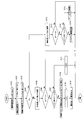
- FIG. 8 is a flowchart of the abnormality determination control of the motor rotational position sensors PS1 and PS2 according to the second embodiment of the present invention.
- the basic configuration is the same as that of the first embodiment, but the main motor rotational position sensor PS1 is When it is determined that there is an abnormality and the sensor used for motor control is switched to the sub-motor rotation position sensor PS2, the voltage command value output to the inverter circuit 24 by the motor drive control unit 32 is reduced. The output of the electric motor 10 is limited.
- step S114 that is, the phase difference ⁇ (Sub) between the sub real axis phase signal ⁇ d (Sub) and the control phase. Is determined to be smaller than the predetermined value ⁇ x, the output of the electric motor 10 is limited by the motor drive control unit 32 (step S116), and then this program ends.
- FIG. 9 is a flowchart of the abnormality determination control of the motor rotational position sensors PS1 and PS2 according to the third embodiment of the present invention, and the motor output restriction process (step S116 in FIG. 8) in the abnormality determination control flow of the second embodiment. ) Is replaced by a motor output gradual decrease process (step S117) in which the motor output is gradually decreased with time by the motor drive control unit 32.
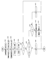
- FIG. 10 is a flowchart of the abnormality determination control of the motor rotational position sensors PS1 and PS2 according to the fourth embodiment of the present invention, and the abnormality determination of each motor rotational position sensor PS1 and PS2 by the sensor abnormality determination unit 49 is determined. This is based on a comparison between the phase difference ⁇ (Main) and the phase difference ⁇ (Sub).
- steps S201 to S203 processing similar to that in steps S101 to S103 in the flowchart of the first embodiment is performed.
- step S204 After calculating the phase difference ⁇ (Sub) with respect to the signal ⁇ dc (steps S204 and S205), it is determined whether or not the motor rotational speed ⁇ r estimated from the steering speed signal ⁇ s is larger than a predetermined value ⁇ x (step S206). .
- the program ends without performing diagnosis to suppress misdiagnosis, whereas when it is determined Yes, the diagnosis is continued and the process proceeds to step S207.
- step S207 it is determined whether or not the difference between the main phase difference ⁇ (Main) calculated in steps S204 and S205 and the sub phase difference ⁇ (Sub) is smaller than a predetermined value ⁇ y. If the determination is Yes, it is assumed that no abnormality has occurred in each of the motor rotational position sensors PS1 and PS2, and after decrementing the motor rotational position sensor abnormality counter Cs (step S208), this program ends. To do.
- step S207 it is determined that an abnormality has occurred in at least one of the motor rotational position sensors PS1 and PS2, and the process proceeds to step S209.
- step S209 it is determined whether or not the motor rotation position sensor abnormality counter Cs is larger than the predetermined value Cx. If it is determined No, the motor rotation position sensor abnormality counter Cs is set to continue the abnormality determination. After incrementing (step S212), this program ends.
- step S209 it is determined that an abnormality has occurred in at least one of the motor rotational position sensors PS1 and PS2, and the steering assist control system is shut off by the failsafe processing unit 34.
- step S210 After performing a process for shifting to a safe state such as a process (step S210), and further giving a warning to the driver, that is, a warning light on the instrument panel of the vehicle is turned on (step S211)
- step S210 After performing a process for shifting to a safe state such as a process (step S210), and further giving a warning to the driver, that is, a warning light on the instrument panel of the vehicle is turned on (step S211)
- step S210 After performing a process for shifting to a safe state such as a process (step S210), and further giving a warning to the driver, that is, a warning light on the instrument panel of the vehicle is turned on (step S211)
- the sensor abnormality determination unit 49 can determine the abnormality of the motor rotational position sensors PS1 and PS2 with high accuracy. As a result, it is possible to improve the safety of the power steering apparatus when driving the electric motor 10 based on the motor rotational position sensors PS1 and PS2.
- [Fifth Embodiment] 11 to 13 show a fifth embodiment of the power steering apparatus and the like according to the present invention. In addition to the configuration of the first embodiment, the abnormality of each motor rotational position sensor PS1 and PS2 by the sensor abnormality determination unit 49 is shown. In the determination, the difference between the main real axis phase signal ⁇ m (Main) and the sub real axis phase signal ⁇ m (Sub) is taken into consideration.
- the control device 11 includes a main real axis phase signal ⁇ d (Main) and a sub real axis phase signal ⁇ d (Sub). ) Is provided.
- a real axis phase comparison unit 53 is provided.
- This real axis phase comparison unit 53 is the absolute value of the difference between the main real axis phase signal ⁇ d (Main) input from each real axis phase signal receiver 44a, 44b and the sub real axis phase signal ⁇ d (Sub). And outputs the calculation result (comparison result) to the sensor abnormality determination unit 49.
- the sensor abnormality determination unit 49 outputs the difference between the main real axis phase signal ⁇ d (Main) or the sub real axis phase signal ⁇ d (Sub) and the control phase signal ⁇ dc, and the real axis phase comparison unit 53.
- the presence / absence of abnormality of the main and sub motor rotational position sensors PS1 and PS2 is determined based on the comparison result.
- the sensor abnormality determination unit 49 calculates the absolute difference between the main real axis phase signal ⁇ d (Main) output from the real axis phase comparison unit 53 and the sub real axis phase signal ⁇ d (Sub). When the value is larger than the predetermined value ⁇ z and the phase differences ⁇ (Main) and ⁇ (Sub) are larger than the predetermined value ⁇ x, it is determined that an abnormality has occurred in the corresponding motor rotational position sensor PS1 (PS2). .
- the sensor abnormality determination unit 49 starts from the state where the motor drive control unit 32 drives and controls the electric motor 10 based on the main real axis phase signal ⁇ d (Main).
- the abnormality determination is started immediately after a predetermined settling time has elapsed without performing the abnormality determination of the sub motor rotational position sensor PS2. It is supposed to be.
- step S304 it is determined whether or not a main sensor diagnosis flag Fm set in step S314 to be described later or a sub sensor diagnosis flag Fs set in step S317 is set, and No (both are not set). ), The process proceeds to step S305.
- step S305 whether or not the absolute value of the difference between the main real axis phase signal ⁇ d (Main) calculated by the real axis phase comparison unit 53 and the sub real axis phase signal ⁇ d (Sub) is greater than a predetermined value ⁇ z. If it is determined No, it is determined that both the motor rotational position sensors PS1 and PS2 are normal and the motor rotational position sensor abnormality counter Cs is cleared (step S321). finish.
- step S305 After incrementing the motor rotation position sensor abnormality counter Cs (step S306), it is determined whether or not the motor rotation position sensor abnormality counter Cs is greater than a predetermined value Cx. (Step S307) If it is determined No, the program ends without confirming the abnormality.
- step S307 it is determined that an abnormality has occurred in at least one of the motor rotational position sensors PS1 and PS2, and thereafter, the motor rotational position sensors PS1 and PS2 The process after step S308 which confirms which has failed is performed.
- step S308 After calculating the main phase difference ⁇ (Main) (step S308), it is determined whether or not the motor rotational speed ⁇ r estimated from the steering speed signal ⁇ s is larger than a predetermined value ⁇ x (step S309).
- step S309 If it is determined No in step S309, it is difficult to determine which of the motor rotational position sensors PS1 and PS2 has failed. Therefore, the fail safe processing unit 34 shuts off the steering assist control system. The processing is performed (step S319), and further warning is given to the driver, that is, a warning lamp on the vehicle instrument panel is turned on (step S320), and then the program ends.
- step S309 it is then determined whether or not the main phase difference ⁇ (Main) is larger than a predetermined value ⁇ x (step S310).
- step S311 If YES is determined, it is determined that the main motor rotational position sensor PS1 has failed, and the real axis phase signal used for motor drive control is changed from the main real axis phase signal ⁇ d (Main) to the sub real axis.
- step S311 the settling timer counter Tset is cleared (step S312), the sub sensor diagnosis flag Fs is set (step S313), and the main sensor diagnosis flag Fm is reset (step S313).
- step S314 After outputting a warning to the driver (step S315), the program is terminated.
- step S310 if it is determined No in step S310, it is assumed that the sub motor rotation position sensor PS2 has failed, the sub sensor diagnosis flag Fs is reset (step S316), and the main sensor diagnosis flag Fm is set ( In step S317), a warning is output to the driver (step S318), and the program ends.
- step S304 if Yes, that is, if an abnormality occurs in at least one of the main and sub motor rotational position sensors PS1 and PS2, and the main sensor diagnosis flag Fm or the sub sensor diagnosis flag Fs is set, Subsequently, the process proceeds to step S322 shown in FIG.
- step S322 it is determined whether or not the sub sensor diagnosis flag Fs is set. If YES is determined, it is subsequently determined whether or not the settling timer counter Tset is larger than a predetermined value Tx (step S322). S323). Here, if it is determined No, the program ends after the settling timer counter Tset is incremented (step S328).
- step S323 determines whether or not the motor rotational speed ⁇ r is larger than a predetermined value ⁇ x.
- the program ends without performing diagnosis to suppress misdiagnosis, whereas when it is determined Yes, the diagnosis is continued and the process proceeds to step S326.
- step S326 it is determined whether or not the sub phase difference ⁇ (Sub) calculated in step S324 is larger than a predetermined value ⁇ x.
- this program ends, assuming that no abnormality has occurred in the sub motor rotational position sensor PS2.
- step S326 it is assumed that an abnormality has occurred in both the main and sub motor rotational position sensors PS1 and PS2, and the steering assist control system by the electric motor 10 is executed by the fail safe processing unit 34. Is interrupted (step S327), the program ends.
- step S322 If it is determined No in step S322, the main phase difference ⁇ (Main) is calculated (step S329), and then it is determined whether or not the motor rotation speed ⁇ r is greater than a predetermined value ⁇ x (step S329). Step S330).
- the program ends without performing diagnosis to suppress misdiagnosis, whereas when it is determined Yes, the diagnosis is continued and the process proceeds to step S331.
- step S331 it is determined whether or not the main phase difference ⁇ (Main) calculated in step S329 is greater than a predetermined value ⁇ x.
- ⁇ x main phase difference
- step S331 it is assumed that an abnormality has occurred in both the main and sub motor rotational position sensors PS1 and PS2, and the steering assist control system by the electric motor 10 is executed by the failsafe processing unit 34. Is cut off (step S332), the program ends.
- the sensor abnormality determination unit 49 can determine the abnormality of each of the motor rotational position sensors PS1 and PS2 with high accuracy.
- the main and sub real axis phase signals ⁇ d (Main) output by the motor rotation position sensors PS1 and PS2 are output.
- ⁇ d (Sub) is also taken into account, so that the accuracy of abnormality determination can be further improved.
- the main motor rotational position sensor PS1 the real axis phase signal ⁇ d (Main) output from the main motor rotational position sensor PS1 is the actual axis phase signal output from the sub motor rotational position sensor PS2. Since the abnormality is determined when it is far from both ⁇ d (Sub) and the control phase signal ⁇ dc, the abnormality of the motor rotational position sensor PS1 can be determined with higher accuracy.
- the sensor abnormality determination unit 49 immediately after the motor rotation position sensor used for driving control of the electric motor 10 is switched from the main motor rotation position sensor PS1 to the sub motor rotation position sensor PS2. Since the abnormality determination of the motor rotational position sensor PS2 is not performed, the abnormality determination is performed based on the sub real axis phase signal ⁇ d (Sub) in a state where the sub motor rotational position sensor PS2 is not fully raised. Since this can be avoided, it is possible to further suppress misjudgment.
- the present invention is not limited to the configuration of each of the embodiments described above, and the configuration can be appropriately changed according to the specifications of the apparatus and the like without departing from the spirit of the invention.
- the control device for the power steering device includes a steering mechanism that transmits the rotation of the steering wheel to the steered wheels, an electric motor that applies a steering assist force to the steering mechanism, the steering mechanism, and the electric motor.
- a transmission mechanism that is provided in between and transmits a rotational force of the electric motor to the steering mechanism; and a first motor rotational position sensor that detects a real axis phase that is a rotational position of a rotor of the electric motor.
- a motor current signal receiving unit for receiving a signal, and a control phase estimation for estimating a control phase which is a phase of an induced voltage generated in the electric motor based on the signal of the current value.
- said first sensor abnormality determining section for determining the presence or absence of abnormality of the first motor rotational position sensor based on the difference of the real axis phase and the control phase, the.
- the power steering device includes a second motor rotation position sensor that detects a real axis phase that is a rotation position of a rotor of the electric motor, and the control device includes: And a motor drive control unit that controls the drive of the electric motor based on the signal of the first real axis phase, and the motor drive control unit determines that the first motor rotational position sensor is abnormal. Then, the electric motor is driven and controlled based on a signal of a second real axis phase which is an output signal of the second motor rotational position sensor.
- the control device compares the first real-axis phase signal with the second real-axis phase signal.
- a phase comparison unit wherein the sensor abnormality determination unit determines whether the first motor rotational position sensor is abnormal based on a difference between the first real axis phase and the control phase and a comparison result of the real axis phase comparison unit. Judging.
- the sensor abnormality determination unit may calculate a difference between the signal of the first real axis phase and the signal of the second real axis phase. When the difference is greater than a predetermined value and the difference between the first real axis phase and the control phase is greater than a predetermined value, it is determined that the first motor rotational position sensor is abnormal.
- the sensor abnormality determination unit drives the electric motor based on the signal of the second real axis phase.
- the control it is determined whether or not the second motor rotational position sensor is abnormal based on a difference between the second real axis phase and the control phase.
- the sensor abnormality determination unit is configured such that the motor drive control unit controls the drive of the electric motor based on the signal of the first real axis phase. After a predetermined time has elapsed since switching to drive control of the electric motor based on the second real axis phase signal, determination of whether or not there is an abnormality in the second motor rotational position sensor is started.
- the sensor abnormality determination unit drives the electric motor based on the signal of the second real axis phase.
- the control it is determined whether or not the second motor rotational position sensor is abnormal based on a difference between the second real axis phase and the control phase.
- the motor drive control unit performs the second control from the drive control of the electric motor based on the signal of the first real axis phase. After switching to the drive control of the electric motor based on the signal of the real axis phase, the drive control of the electric motor is performed so that the output of the electric motor decreases.
- the motor drive control unit performs the second control from the drive control of the electric motor based on the signal of the first real axis phase. After switching to the drive control of the electric motor based on the signal of the real axis phase, the drive control of the electric motor is performed so that the output of the electric motor gradually decreases.
- the sensor abnormality determination unit includes a difference between the first real axis phase and the control phase, and the second real axis phase. And whether there is an abnormality in the first motor rotational position sensor based on a comparison between the control phase differences.
- the sensor abnormality determination unit may detect the first motor rotational position sensor when the rotational speed of the electric motor is equal to or lower than a predetermined value. Abnormality judgment is not performed.
- the rotational speed of the electric motor is estimated based on a signal other than the output signal of the first motor rotational position sensor.
- the control device includes a steering angle signal receiving unit that receives a steering angle signal that is a rotation angle of the steering wheel, The rotational speed of the electric motor is estimated based on the steering angle signal.
- the power steering apparatus is provided on the steering wheel side of the torsion bar provided in the steering mechanism and on the steering wheel side.
- a steering angle sensor that detects the steering angle, and the rotational speed of the electric motor is estimated in consideration of the amount of twist of the torsion bar.
- the sensor abnormality determination unit is configured to have a d-axis voltage Vdc that is a magnetic pole direction of the rotor of the electric motor, and is orthogonal to the d-axis. Calculating the difference between the first real axis phase and the control phase based on the q-axis voltage Vqc, the d-axis detection current Idc, the q-axis detection current Iqc, and the rotation speed ⁇ 1 of the control phase; Based on the calculation result, it is determined whether or not the first motor rotational position sensor is abnormal.
- the sensor abnormality determination unit further considers the resistance r of the winding of the electric motor and the inductance Lq of the electric motor. The difference between the first real axis phase and the control phase is calculated.
- the sensor abnormality determination unit is a formula
- the difference between the first real axis phase and the control phase is calculated.
- the sensor abnormality determination unit is a formula
- the difference between the first real axis phase and the control phase is calculated.
- the power steering device is provided with a steering mechanism that transmits the rotation of the steering wheel to the steered wheels, an electric motor that applies a steering assist force to the steering mechanism, and a space between the steering mechanism and the electric motor.
- a transmission mechanism that transmits the rotational force of the electric motor to the steering mechanism, a first motor rotational position sensor that detects a real axis phase that is a rotational position of the rotor of the electric motor, and the electric motor.
- a real steering phase signal receiving unit that receives a first real axis phase signal output from the first motor rotational position sensor.
- a motor current signal receiving unit that receives a signal of a current value flowing through the electric motor, and an induced voltage generated in the electric motor based on the signal of the current value
- a control phase estimation unit that estimates a control phase that is a phase
- a sensor abnormality determination unit that determines whether there is an abnormality in the first motor rotational position sensor based on a difference between the first real axis phase and the control phase;
- the power steering device includes a second motor rotational position sensor that detects a real axis phase that is a rotational position of a rotor of the electric motor, and the control device includes the first And a motor drive control unit that drives and controls the electric motor based on the signal of the real axis phase of 1 when the motor drive control unit determines that the first motor rotation position sensor is abnormal.
- the electric motor is driven and controlled based on a second real axis phase signal which is an output signal of the second motor rotational position sensor.
Landscapes
- Engineering & Computer Science (AREA)
- Chemical & Material Sciences (AREA)
- Combustion & Propulsion (AREA)
- Transportation (AREA)
- Mechanical Engineering (AREA)
- Power Engineering (AREA)
- Steering Control In Accordance With Driving Conditions (AREA)
- Power Steering Mechanism (AREA)
- Control Of Motors That Do Not Use Commutators (AREA)
Abstract
Description
〔第1実施形態〕
前記パワーステアリング装置は、図1~図3に示すように、図示外のステアリングホイールの回転を図示外の転舵輪に伝達する操舵機構1と、操舵情報等に基づき操舵機構1に操舵アシスト力を付与して運転者のステアリング操作を補助する操舵アシスト機構2と、を備えている。



〔第1実施形態の作用効果〕
したがって、以上のように構成されたパワーステアリング装置等によれば、センサ異常判断部49によって各モータ回転位置センサPS1,PS2の異常を判断することができる。この結果、各モータ回転位置センサPS1,PS2に基づいて電動モータ10を駆動制御する際の前記パワーステアリング装置の安全性を向上することができる。
〔第2実施形態〕
図8は本発明の第2実施形態に係るモータ回転位置センサPS1,PS2の異常判断制御のフローチャートであって、基本構成は第1実施形態と同様であるが、メインのモータ回転位置センサPS1が異常と判断されて、モータ制御に用いられるセンサがサブのモータ回転位置センサPS2に切り換えられた場合に、モータ駆動制御部32がインバータ回路24に出力する電圧指令値を減少させる等の手段により、電動モータ10の出力を制限するようになっている。
〔第3実施形態〕
図9は、本発明の第3実施形態に係るモータ回転位置センサPS1,PS2の異常判断制御のフローチャートであって、第2実施形態の異常判断制御フローにおけるモータ出力制限処理(図8のステップS116)を、モータ駆動制御部32によってモータ出力を時間経過に伴い徐々に低下させるモータ出力漸減処理(ステップS117)に置き換えたものである。
〔第4実施形態〕
図10は、本発明の第4実施形態に係るモータ回転位置センサPS1,PS2の異常判断制御のフローチャートであって、センサ異常判断部49による各モータ回転位置センサPS1,PS2の異常判断を、位相差Δθ(Main)と位相差Δθ(Sub)との比較に基づいて行うようにしたものである。
〔第5実施形態〕
図11~図13は、本発明に係るパワーステアリング装置等の第5実施形態を示し、前記第1実施形態の構成に加えて、センサ異常判断部49による各モータ回転位置センサPS1,PS2の異常判断に際し、メインの実軸位相信号θm(Main)とサブの実軸位相信号θm(Sub)との差を考慮するようにしたものである。


Claims (20)
- ステアリングホイールの回転を転舵輪に伝達する操舵機構と、
該操舵機構に操舵アシスト力を付与する電動モータと、
前記操舵機構と前記電動モータの間に設けられ、前記電動モータの回転力を前記操舵機構に伝達する伝達機構と、
前記電動モータの回転子の回転位置である実軸位相を検出する第1のモータ回転位置センサと、
を備えたパワーステアリング装置の制御装置であって、
前記第1のモータ回転位置センサから出力された第1の実軸位相の信号を受信する実軸位相信号受信部と、
前記電動モータに流れる電流値の信号を受信するモータ電流信号受信部と、
前記電流値の信号に基づき前記電動モータに発生する誘起電圧の位相である制御位相を推定する制御位相推定部と、
前記第1の実軸位相と前記制御位相の差に基づき前記第1のモータ回転位置センサの異常の有無を判断するセンサ異常判断部と、
を有することを特徴とするパワーステアリング装置の制御装置。 - 請求項1に記載のパワーステアリング装置の制御装置において、
前記パワーステアリング装置は、前記電動モータの回転子の回転位置である実軸位相を検出する第2のモータ回転位置センサを有し、
前記制御装置は、前記第1の実軸位相の信号に基づき前記電動モータを駆動制御するモータ駆動制御部を有し、
該モータ駆動制御部は、前記第1のモータ回転位置センサが異常であると判断されたとき、前記第2のモータ回転位置センサの出力信号である第2の実軸位相の信号に基づき前記電動モータを駆動制御することを特徴とするパワーステアリング装置の制御装置。 - 請求項2に記載のパワーステアリング装置の制御装置は、
前記第1の実軸位相の信号と前記第2の実軸位相の信号とを比較する実軸位相比較部を備え、
前記センサ異常判断部は、前記第1の実軸位相と前記制御位相の差および前記実軸位相比較部の比較結果に基づき前記第1のモータ回転位置センサの異常の有無を判断することを特徴とするパワーステアリング装置の制御装置。 - 請求項3に記載のパワーステアリング装置の制御装置において、
前記センサ異常判断部は、前記第1の実軸位相の信号と前記第2の実軸位相の信号の差が所定値よりも大きく、かつ前記第1の実軸位相と前記制御位相の差が所定値よりも大きいとき、前記第1のモータ回転位置センサの異常と判断することを特徴とするパワーステアリング装置の制御装置。 - 請求項4に記載のパワーステアリング装置の制御装置において、
前記センサ異常判断部は、前記モータ駆動制御部が前記第2の実軸位相の信号に基づき前記電動モータを駆動制御するとき、前記第2の実軸位相と前記制御位相の差に基づき前記第2のモータ回転位置センサの異常の有無を判断することを特徴とするパワーステアリング装置の制御装置。 - 請求項5に記載のパワーステアリング装置の制御装置において、
前記センサ異常判断部は、前記モータ駆動制御部が前記第1の実軸位相の信号による前記電動モータの駆動制御から前記第2の実軸位相の信号による前記電動モータの駆動制御に切り替えてから所定時間が経過した後に、前記第2のモータ回転位置センサの異常の有無の判断を開始することを特徴とするパワーステアリング装置の制御装置。 - 請求項2に記載のパワーステアリング装置の制御装置において、
前記センサ異常判断部は、前記モータ駆動制御部が前記第2の実軸位相の信号に基づき前記電動モータを駆動制御するとき、前記第2の実軸位相と前記制御位相の差に基づき前記第2のモータ回転位置センサの異常の有無を判断することを特徴とするパワーステアリング装置の制御装置。 - 請求項2に記載のパワーステアリング装置の制御装置において、
前記モータ駆動制御部は、前記第1の実軸位相の信号に基づく前記電動モータの駆動制御から前記第2の実軸位相の信号に基づく前記電動モータの駆動制御に切り替えた後、前記電動モータの出力が減少するように前記電動モータを駆動制御することを特徴とするパワーステアリング装置の制御装置。 - 請求項2に記載のパワーステアリング装置の制御装置において、
前記モータ駆動制御部は、前記第1の実軸位相の信号に基づく前記電動モータの駆動制御から前記第2の実軸位相の信号に基づく前記電動モータの駆動制御に切り替えた後、前記電動モータの出力が漸減するように前記電動モータを駆動制御することを特徴とするパワーステアリング装置の制御装置。 - 請求項2に記載のパワーステアリング装置の制御装置において、
前記センサ異常判断部は、前記第1の実軸位相と前記制御位相の差、および前記第2の実軸位相と前記制御位相の差の比較に基づき前記第1のモータ回転位置センサの異常の有無を判断することを特徴とするパワーステアリング装置の制御装置。 - 請求項1に記載のパワーステアリング装置の制御装置において、
前記センサ異常判断部は、前記電動モータの回転速度が所定値以下のとき、前記第1のモータ回転位置センサの異常判断を行わないことを特徴とするパワーステアリング装置の制御装置。 - 請求項11に記載のパワーステアリング装置の制御装置において、
前記電動モータの回転速度は、前記第1のモータ回転位置センサの出力信号以外の信号に基づき推定されることを特徴とするパワーステアリング装置の制御装置。 - 請求項12に記載のパワーステアリング装置の制御装置は、前記ステアリングホイールの回転角である舵角の信号を受信する舵角信号受信部を備え、
前記電動モータの回転速度は、前記舵角の信号に基づき推定されることを特徴とするパワーステアリング装置の制御装置。 - 請求項13に記載のパワーステアリング装置の制御装置において、
前記パワーステアリング装置は、前記操舵機構に設けられたトーションバーと、該トーションバーよりも前記ステアリングホイール側に設けられ、前記舵角を検出する舵角センサと、を備え、
前記電動モータの回転速度は、前記トーションバーの捩れ量を考慮して推定されることを特徴とするパワーステアリング装置の制御装置。 - 請求項1に記載のパワーステアリング装置の制御装置において、
前記センサ異常判断部は、前記電動モータの回転子の磁極方向であるd軸の電圧Vdc、前記d軸と直交するq軸の電圧Vqc、前記d軸の検出電流Idc、前記q軸の検出電流Iqc、および前記制御位相の回転速度ω1に基づき前記第1の実軸位相と前記制御位相の差を演算し、この演算結果に基づいて前記第1のモータ回転位置センサの異常の有無を判断することを特徴とするパワーステアリング装置の制御装置。 - 請求項15に記載のパワーステアリング装置の制御装置において、
前記センサ異常判断部は、前記電動モータの巻線の抵抗rおよび前記電動モータのインダクタンスLqを更に考慮して前記第1の実軸位相と前記制御位相の差を演算することを特徴とするパワーステアリング装置の制御装置。 - 請求項16に記載のパワーステアリング装置の制御装置において、
前記センサ異常判断部は、式

- 請求項17に記載のパワーステアリング装置の制御装置において、
前記センサ異常判断部は、式

- ステアリングホイールの回転を転舵輪に伝達する操舵機構と、
前記操舵機構に操舵アシスト力を付与する電動モータと、
前記操舵機構と前記電動モータの間に設けられ、前記電動モータの回転力を前記操舵機構に伝達する伝達機構と、
前記電動モータの回転子の回転位置である実軸位相を検出する第1のモータ回転位置センサと、
前記電動モータを駆動制御する制御装置と、を備えたパワーステアリング装置であって、
前記制御装置は、
前記第1のモータ回転位置センサから出力された第1の実軸位相の信号を受信する実軸位相信号受信部と、
前記電動モータに流れる電流値の信号を受信するモータ電流信号受信部と、
前記電流値の信号に基づき前記電動モータに発生する誘起電圧の位相である制御位相を推定する制御位相推定部と、
前記第1の実軸位相と前記制御位相の差に基づき前記第1のモータ回転位置センサの異常の有無を判断するセンサ異常判断部と、
を有することを特徴とするパワーステアリング装置。 - 請求項19に記載のパワーステアリング装置は、前記電動モータの回転子の回転位置である実軸位相を検出する第2のモータ回転位置センサを有し、
前記制御装置は、前記第1の実軸位相の信号に基づき前記電動モータを駆動制御するモータ駆動制御部を有すると共に、
該モータ駆動制御部は、前記第1のモータ回転位置センサが異常であると判断されたとき、前記第2のモータ回転位置センサの出力信号である第2の実軸位相の信号に基づき前記電動モータを駆動制御することを特徴とするパワーステアリング装置。
Priority Applications (5)
| Application Number | Priority Date | Filing Date | Title |
|---|---|---|---|
| CN201680051703.4A CN108093676B (zh) | 2015-09-10 | 2016-07-29 | 动力转向装置的控制装置及动力转向装置 |
| KR1020187006216A KR20180037030A (ko) | 2015-09-10 | 2016-07-29 | 파워 스티어링 장치의 제어 장치 및 파워 스티어링 장치 |
| US15/752,679 US10745045B2 (en) | 2015-09-10 | 2016-07-29 | Control device for power steering device, and power steering device |
| DE112016004093.8T DE112016004093T5 (de) | 2015-09-10 | 2016-07-29 | Servolenkvorrichtungs-steuereinrichtung und servolenkvorrichtung |
| JP2017539059A JP6557345B2 (ja) | 2015-09-10 | 2016-07-29 | パワーステアリング装置の制御装置及びパワーステアリング装置 |
Applications Claiming Priority (2)
| Application Number | Priority Date | Filing Date | Title |
|---|---|---|---|
| JP2015-178051 | 2015-09-10 | ||
| JP2015178051 | 2015-09-10 |
Publications (1)
| Publication Number | Publication Date |
|---|---|
| WO2017043213A1 true WO2017043213A1 (ja) | 2017-03-16 |
Family
ID=58239678
Family Applications (1)
| Application Number | Title | Priority Date | Filing Date |
|---|---|---|---|
| PCT/JP2016/072288 Ceased WO2017043213A1 (ja) | 2015-09-10 | 2016-07-29 | パワーステアリング装置の制御装置及びパワーステアリング装置 |
Country Status (6)
| Country | Link |
|---|---|
| US (1) | US10745045B2 (ja) |
| JP (1) | JP6557345B2 (ja) |
| KR (1) | KR20180037030A (ja) |
| CN (1) | CN108093676B (ja) |
| DE (1) | DE112016004093T5 (ja) |
| WO (1) | WO2017043213A1 (ja) |
Cited By (2)
| Publication number | Priority date | Publication date | Assignee | Title |
|---|---|---|---|---|
| CN109664934A (zh) * | 2017-10-16 | 2019-04-23 | 株式会社万都 | 电动转向系统的故障安全控制装置、控制方法及转向系统 |
| KR20220086266A (ko) * | 2020-12-16 | 2022-06-23 | 현대모비스 주식회사 | 전동식 조향 시스템에서 dc 모터의 속도 추정 장치 및 그 방법 |
Families Citing this family (6)
| Publication number | Priority date | Publication date | Assignee | Title |
|---|---|---|---|---|
| US10822024B2 (en) * | 2017-11-06 | 2020-11-03 | Steering Solutions Ip Holding Corporation | Current sensor fault mitigation for steering systems with permanent magnet DC drives |
| US11440580B2 (en) | 2018-06-01 | 2022-09-13 | Mando Corporation | Electric power steering apparatus and control method for the same, apparatus for synchronization dual steering motor and method i'hereof |
| JP7141893B2 (ja) * | 2018-09-04 | 2022-09-26 | 日立Astemo株式会社 | ステアリング装置 |
| DE102019106568A1 (de) * | 2019-03-14 | 2020-09-17 | Zf Automotive Germany Gmbh | Verfahren und Vorrichtung zum Bestimmen eines Sensoroffsets |
| CN114167154A (zh) * | 2021-12-07 | 2022-03-11 | 西安西变组件有限公司 | 一种相序自校验的电动机及相序校验方法 |
| US20250392241A1 (en) * | 2024-06-21 | 2025-12-25 | Steering Solutions Ip Holding Corporation | Motion sensing diagnostics for permanent magnet dc motor drive |
Citations (2)
| Publication number | Priority date | Publication date | Assignee | Title |
|---|---|---|---|---|
| JP2004274947A (ja) * | 2003-03-11 | 2004-09-30 | Aisin Seiki Co Ltd | ブラシレスモータ制御装置 |
| JP2005335591A (ja) * | 2004-05-27 | 2005-12-08 | Nissan Motor Co Ltd | 電動式パワーステアリング装置及びブラシレスモータの異常検出装置 |
Family Cites Families (10)
| Publication number | Priority date | Publication date | Assignee | Title |
|---|---|---|---|---|
| JP2001119914A (ja) * | 1999-10-15 | 2001-04-27 | Yamaha Motor Co Ltd | 電動機の回転子位置検出装置 |
| JP3593050B2 (ja) * | 2001-03-27 | 2004-11-24 | 三菱電機株式会社 | 位置検出装置の異常検出方法および装置並びに電動パワーステアリング装置 |
| JP4355189B2 (ja) * | 2003-10-10 | 2009-10-28 | 日本精工株式会社 | 電動パワーステアリング装置の制御装置 |
| JP4589093B2 (ja) | 2004-12-10 | 2010-12-01 | 日立オートモティブシステムズ株式会社 | 同期モータ駆動装置及び方法 |
| JP2006273155A (ja) * | 2005-03-29 | 2006-10-12 | Showa Corp | 電動パワーステアリング装置 |
| JP2010057228A (ja) * | 2008-08-27 | 2010-03-11 | Hitachi Ltd | モータ制御装置 |
| JP5165545B2 (ja) * | 2008-12-08 | 2013-03-21 | 本田技研工業株式会社 | 電動機の磁極位置推定装置 |
| JP4911231B2 (ja) * | 2010-02-15 | 2012-04-04 | 株式会社デンソー | 回転電機制御装置、および、これを用いた電動パワーステアリング装置 |
| US20130147408A1 (en) * | 2010-09-15 | 2013-06-13 | Panasonic Corporation | Motor current phase detecting device and motor drive device having same |
| JP5409678B2 (ja) * | 2011-03-17 | 2014-02-05 | 三菱電機株式会社 | 電動機制御装置 |
-
2016
- 2016-07-29 DE DE112016004093.8T patent/DE112016004093T5/de not_active Withdrawn
- 2016-07-29 CN CN201680051703.4A patent/CN108093676B/zh active Active
- 2016-07-29 US US15/752,679 patent/US10745045B2/en active Active
- 2016-07-29 JP JP2017539059A patent/JP6557345B2/ja active Active
- 2016-07-29 WO PCT/JP2016/072288 patent/WO2017043213A1/ja not_active Ceased
- 2016-07-29 KR KR1020187006216A patent/KR20180037030A/ko not_active Withdrawn
Patent Citations (2)
| Publication number | Priority date | Publication date | Assignee | Title |
|---|---|---|---|---|
| JP2004274947A (ja) * | 2003-03-11 | 2004-09-30 | Aisin Seiki Co Ltd | ブラシレスモータ制御装置 |
| JP2005335591A (ja) * | 2004-05-27 | 2005-12-08 | Nissan Motor Co Ltd | 電動式パワーステアリング装置及びブラシレスモータの異常検出装置 |
Cited By (3)
| Publication number | Priority date | Publication date | Assignee | Title |
|---|---|---|---|---|
| CN109664934A (zh) * | 2017-10-16 | 2019-04-23 | 株式会社万都 | 电动转向系统的故障安全控制装置、控制方法及转向系统 |
| KR20220086266A (ko) * | 2020-12-16 | 2022-06-23 | 현대모비스 주식회사 | 전동식 조향 시스템에서 dc 모터의 속도 추정 장치 및 그 방법 |
| KR102496766B1 (ko) * | 2020-12-16 | 2023-02-07 | 현대모비스 주식회사 | 전동식 조향 시스템에서 dc 모터의 속도 추정 장치 및 그 방법 |
Also Published As
| Publication number | Publication date |
|---|---|
| JP6557345B2 (ja) | 2019-08-07 |
| KR20180037030A (ko) | 2018-04-10 |
| US20190023309A1 (en) | 2019-01-24 |
| DE112016004093T5 (de) | 2018-06-07 |
| CN108093676B (zh) | 2022-01-14 |
| CN108093676A (zh) | 2018-05-29 |
| US10745045B2 (en) | 2020-08-18 |
| JPWO2017043213A1 (ja) | 2018-07-26 |
Similar Documents
| Publication | Publication Date | Title |
|---|---|---|
| JP6557345B2 (ja) | パワーステアリング装置の制御装置及びパワーステアリング装置 | |
| US10266198B2 (en) | Motor control device | |
| JP4329792B2 (ja) | 電動パワーステアリング装置 | |
| CN106029471B (zh) | 动力转向装置及动力转向装置的控制装置 | |
| EP2024220B1 (en) | Electric power steering apparatus and method for controlling the electric power steering apparatus | |
| US8855857B2 (en) | Electric motor controller and electric motor controller for vehicle steering apparatus | |
| US8909429B2 (en) | Vehicle steering system | |
| US8380398B2 (en) | Motor control unit and motor control unit for vehicle steering apparatus | |
| EP3219579A1 (en) | Motor control device and steering control device | |
| EP3331158A1 (en) | Electric power steering apparatus | |
| EP2177422A2 (en) | Vehicle steering apparatus | |
| EP2279927A2 (en) | Electric power steering system | |
| US8855858B2 (en) | Motor control unit and vehicle steering system | |
| EP2228899A1 (en) | Motor control unit and motor control unit for vehicle steering apparatus | |
| KR20120138454A (ko) | 전동식 동력 조향장치의 제어방법 | |
| JP2018128429A (ja) | 回転検出装置 | |
| EP3483036B1 (en) | Steering control apparatus | |
| EP3254929B1 (en) | Vehicle steering system | |
| JP5263079B2 (ja) | 電動パワーステアリング装置 | |
| JP3915595B2 (ja) | レゾルバを用いた回転角度検出装置およびこの装置を用いた制御装置 | |
| JP5181540B2 (ja) | 電動パワーステアリング装置 | |
| US12351251B2 (en) | Motor control device and motor control method | |
| JP5287698B2 (ja) | 電動パワーステアリング装置 |
Legal Events
| Date | Code | Title | Description |
|---|---|---|---|
| 121 | Ep: the epo has been informed by wipo that ep was designated in this application |
Ref document number: 16844077 Country of ref document: EP Kind code of ref document: A1 |
|
| ENP | Entry into the national phase |
Ref document number: 2017539059 Country of ref document: JP Kind code of ref document: A |
|
| ENP | Entry into the national phase |
Ref document number: 20187006216 Country of ref document: KR Kind code of ref document: A |
|
| WWE | Wipo information: entry into national phase |
Ref document number: 112016004093 Country of ref document: DE |
|
| 122 | Ep: pct application non-entry in european phase |
Ref document number: 16844077 Country of ref document: EP Kind code of ref document: A1 |