WO2017042893A1 - 電気装置 - Google Patents
電気装置 Download PDFInfo
- Publication number
- WO2017042893A1 WO2017042893A1 PCT/JP2015/075513 JP2015075513W WO2017042893A1 WO 2017042893 A1 WO2017042893 A1 WO 2017042893A1 JP 2015075513 W JP2015075513 W JP 2015075513W WO 2017042893 A1 WO2017042893 A1 WO 2017042893A1
- Authority
- WO
- WIPO (PCT)
- Prior art keywords
- wall
- housing
- air passage
- wall portion
- module
- Prior art date
- Legal status (The legal status is an assumption and is not a legal conclusion. Google has not performed a legal analysis and makes no representation as to the accuracy of the status listed.)
- Ceased
Links
Images




Classifications
-
- H—ELECTRICITY
- H01—ELECTRIC ELEMENTS
- H01M—PROCESSES OR MEANS, e.g. BATTERIES, FOR THE DIRECT CONVERSION OF CHEMICAL ENERGY INTO ELECTRICAL ENERGY
- H01M50/00—Constructional details or processes of manufacture of the non-active parts of electrochemical cells other than fuel cells, e.g. hybrid cells
- H01M50/20—Mountings; Secondary casings or frames; Racks, modules or packs; Suspension devices; Shock absorbers; Transport or carrying devices; Holders
- H01M50/204—Racks, modules or packs for multiple batteries or multiple cells
-
- H—ELECTRICITY
- H01—ELECTRIC ELEMENTS
- H01M—PROCESSES OR MEANS, e.g. BATTERIES, FOR THE DIRECT CONVERSION OF CHEMICAL ENERGY INTO ELECTRICAL ENERGY
- H01M10/00—Secondary cells; Manufacture thereof
- H01M10/60—Heating or cooling; Temperature control
- H01M10/61—Types of temperature control
- H01M10/613—Cooling or keeping cold
-
- H—ELECTRICITY
- H01—ELECTRIC ELEMENTS
- H01M—PROCESSES OR MEANS, e.g. BATTERIES, FOR THE DIRECT CONVERSION OF CHEMICAL ENERGY INTO ELECTRICAL ENERGY
- H01M10/00—Secondary cells; Manufacture thereof
- H01M10/60—Heating or cooling; Temperature control
- H01M10/65—Means for temperature control structurally associated with the cells
- H01M10/655—Solid structures for heat exchange or heat conduction
- H01M10/6556—Solid parts with flow channel passages or pipes for heat exchange
- H01M10/6557—Solid parts with flow channel passages or pipes for heat exchange arranged between the cells
-
- Y—GENERAL TAGGING OF NEW TECHNOLOGICAL DEVELOPMENTS; GENERAL TAGGING OF CROSS-SECTIONAL TECHNOLOGIES SPANNING OVER SEVERAL SECTIONS OF THE IPC; TECHNICAL SUBJECTS COVERED BY FORMER USPC CROSS-REFERENCE ART COLLECTIONS [XRACs] AND DIGESTS
- Y02—TECHNOLOGIES OR APPLICATIONS FOR MITIGATION OR ADAPTATION AGAINST CLIMATE CHANGE
- Y02E—REDUCTION OF GREENHOUSE GAS [GHG] EMISSIONS, RELATED TO ENERGY GENERATION, TRANSMISSION OR DISTRIBUTION
- Y02E60/00—Enabling technologies; Technologies with a potential or indirect contribution to GHG emissions mitigation
- Y02E60/10—Energy storage using batteries
Definitions
- Embodiments of the present invention relate to an electrical device.
- an electric device in which an air passage extending along a floor surface is provided between two modules adjacent in a direction away from the floor surface in a casing.
- the electrical apparatus includes, for example, a plurality of modules and a housing.
- the plurality of modules generate heat.
- the housing is provided with a plurality of shelves that support each of the modules side by side in a first direction away from the floor surface, and is inclined with respect to the floor surface between two modules adjacent in the first direction.
- a first air passage extending along a second direction is provided.
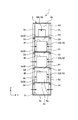
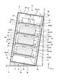
- FIG. 1 is an exemplary side view (partially sectional view) of the electric device according to the first embodiment.
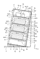
- 2 is a cross-sectional view taken along the line II-II in FIG.
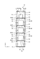
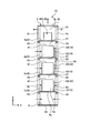
- FIG. 3 is an exemplary side view (partially sectional view) of the electric device according to the second embodiment.
- 4 is a cross-sectional view taken along the line IV-IV in FIG.
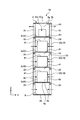
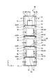
- FIG. 5 is an exemplary side view (partially sectional view) of the electric device according to the third embodiment.
- 6 is a cross-sectional view taken along the line VI-VI in FIG.
- FIG. 7 is an exemplary side view (partially sectional view) of the electric device according to the fourth embodiment.
- FIG. 1 is an exemplary side view (partially sectional view) of the electric device according to the first embodiment.
- 2 is a cross-sectional view taken along the line II-II in FIG.
- FIG. 3 is an exemplary side view (partially sectional view) of the electric device according to
- FIG. 8 is an exemplary side view (partially sectional view) of the electric device according to the fifth embodiment.
- 9 is a cross-sectional view taken along the line IX-IX in FIG.
- FIG. 10 is an exemplary side view (partially sectional view) of the electric device according to the sixth embodiment.
- 11 is a cross-sectional view taken along the line XI-XI in FIG.
- the same components are included in the embodiments disclosed below. Therefore, below, the same code
- the electric device is configured as a storage battery device is illustrated, but the electric device of the present embodiment is not limited to this, and for example, heat is generated in a housing such as a control panel device. It can be configured as various electric devices provided with a plurality of modules (electronic components).
- the storage battery device 1 (assembled battery device, battery rack, electric device) includes, for example, a housing 2, a battery module 3 and a control module 4 as a plurality of modules 10, and a support member. 5 is provided.
- the module 10 may be referred to as a unit or the like, and the housing 2 may be referred to as a first housing or the like.
- a plurality of storage battery devices 1 are mounted in a container, and the storage battery system is configured by connecting the plurality of storage battery devices 1 in series or in parallel.
- This container-type storage battery system can be used, for example, as a power source for outdoor equipment or an emergency power source.
- the support member 5 has, for example, a right triangle shape or a wedge shape in the line of sight (side view) shown in FIG.
- the support member 5 has a first surface 5a that faces the floor surface P of the container, and a second surface 5b that faces the opposite side of the first surface 5a and supports the housing 2.
- the second surface 5b is inclined with respect to the floor surface P (plane).
- the second surface 5b is inclined so as to gradually move away from the floor surface P from the end on the side wall S (vertical wall, standing wall) side of the container toward the end opposite to the side wall S.
- the angle at which the floor surface P and the second surface 5b intersect is, for example, an acute angle of 45 ° or less, preferably 15 ° or less, and, for example, 5 ° in the present embodiment.
- the support member 5 only needs to have a structure that can support the housing 2 in an inclined state, and the shape of the support member 5 is not limited to that shown in FIG.
- the second surface 5b is an example of an inclined surface.
- the housing 2 has a rectangular parallelepiped shape that is long in the vertical direction (vertical direction).
- the housing 2 includes, for example, a plurality of wall portions 2a and 2b, a plurality of column portions 2c, a plurality of beam portions 2d, and the like.
- the housing 2 has a posture in which any one of the plurality of wall portions 2 a and 2 b (for example, the wall portion 2 a) is along the second surface 5 b (inclined surface). Installed.
- the wall 2a is an example of a first wall. In the following, for the sake of convenience, the direction is defined with reference to the posture of the wall 2a along the second surface 5b.
- the X direction is the depth direction (front-rear direction) of the housing 2
- the Y direction is the width direction (short direction) of the housing 2
- the Z direction is the height direction (longitudinal direction) of the housing 2.
- the X direction, the Y direction, and the Z direction are orthogonal to each other.
- the X direction is an example of a second direction inclined with respect to the floor surface P
- the Y direction is an example of a third direction that intersects the second direction and extends along the wall portion 2a.
- Z direction is an example of a first direction away from the floor surface P.
- the wall 2a and the wall 2b are both along a direction (X direction and Y direction) orthogonal to the Z direction, and are parallel to each other with a gap in the Z direction. Is provided.
- the wall 2a can be referred to as a lower wall or a bottom wall.
- the wall portion 2a faces the second surface 5b and overlaps the floor surface P of the container with the support member 5 interposed therebetween.
- the wall part 2b is called an upper wall part, a top wall part, etc., and faces the ceiling surface (not shown) of a container.
- one side of the wall 2b in the X direction that is, the floor surface P side, the right end 2b1 in FIG.
- the wall portion 2b may be provided with a flange portion that extends from the end portion 2b1 along the side wall S, and the flange portion and the side wall S may be coupled to each other by a coupling tool (for example, a bolt or a screw). .
- the walls 2a and 2b can also be referred to as panels.
- the plurality of (for example, four) pillar portions 2c are each configured in a rod shape extending in the Z direction.
- the column part 2c can be configured in a hollow prismatic shape, for example. As shown in FIGS. 1 and 2, the column part 2c is provided at each of the four corners of the wall parts 2a and 2b, and extends between the wall part 2a and the wall part 2b.
- the column part 2c may also be referred to as a first structural material, a vertical wall part, a frame, or the like.
- the wall portions 2a and 2b and the column portion 2c can be coupled to each other by a coupling tool such as a screw or an adhesive.
- the plurality of (for example, eight) beam portions 2d are each configured in a bar shape extending along the X direction.
- the beam portion 2d can be configured in a hollow prism shape, for example.
- Each of the beam portions 2d is positioned between the wall portion 2a and the wall portion 2b and extends between the two column portions 2c arranged in the X direction.
- four beam portions 2d positioned on one side in the Y direction are provided at equal intervals in the Z direction, and four beams positioned on the other side in the Y direction.
- Two beam portions 2d are provided at equal intervals in the Z direction.
- the beam portion 2d can also be referred to as a second structural material, a lateral wall portion, a frame, or the like.
- the column portion 2c and the beam portion 2d can be coupled to each other by, for example, a coupling tool such as a screw or an adhesive.
- a coupling tool such as a screw or an adhesive.
- the pillar part 2c and the beam part 2d may be an angle material whose section is L-shaped.
- a plurality of wall portions 2 e along the wall portions 2 a and 2 b are provided in the housing 2.
- each of the wall portions 2e is located between the wall portion 2a and the wall portion 2b and extends between the two beam portions 2d arranged in the Y direction.
- the wall 2e can also be referred to as a third structural material, a shelf board, a partition wall, a support wall, a tray member, or the like.
- the beam portion 2d and the wall portion 2e can be coupled to each other by a coupling tool such as a screw or an adhesive. As shown in FIG.
- the width of the wall 2e along the X direction is configured to be smaller (shorter) than the width of the beam 2d along the X direction, and the wall 2e is formed of the beam 2d. It is positioned close to the center in the X direction. That is, an opening 2t penetrating between two beam portions 2d arranged in the Y direction is formed on one side and the other side in the X direction of the wall portion 2e. In the opening 2t, the upward air flow shown in FIG. 1 is allowed to pass.
- the wall 2e is provided with a space in the Z direction together with the wall 2a and the wall 2b.
- a plurality of shelves 9 that support each of the modules 10 are formed in the housing 2.
- the shelf 9 can also be referred to as a storage unit, a storage room, a storage region, or the like.
- the control module 4 is accommodated in the uppermost shelf 9 among the plurality of shelves 9 arranged in the Z direction, and the lowermost shelf 9.
- the module 10 is not provided.
- the battery modules 3 are accommodated in a plurality of (for example, three) shelves 9 between the upper shelves 9 and the lower shelves 9, respectively.
- the housing 2 has no wall portion other than the wall portions 2a, 2b, and 2e that are separated from each other in the Z direction. In other words, except for the column part 2c and the beam part 2d, both ends in the X direction and both ends in the Y direction of the housing 2 are open.
- the battery module 3 includes, for example, a housing 6 and a plurality of battery cells 7.
- the battery cell 7 is an example of a heat generating component.
- the battery cell 7 can be composed of, for example, a lithium ion secondary battery.
- the battery cell 7 may be another secondary battery such as a nickel metal hydride battery, a nickel cadmium battery, or a lead storage battery.
- a plurality of (for example, twelve) battery cells 7 are accommodated in the housing 6 in a state of being arranged in an example along the X direction.
- the battery module 3 may be referred to as an assembled battery or the like, and the battery cell 7 may be referred to as a single battery or the like.
- the housing 6 can also be referred to as a second housing.
- the housing 6 has a rectangular parallelepiped shape that is long in the horizontal direction (left-right direction).
- the housing 6 has a plurality of wall portions 6a to 6f.
- both the wall 6a and the wall 6c are along a direction (Y direction and Z direction) orthogonal to the X direction, and are parallel to each other with an interval in the X direction. Is provided.
- both the wall 6b and the wall 6d are along a direction (X direction and Z direction) orthogonal to the Y direction, with a gap in the Y direction. They are provided parallel to each other.
- the wall portions 6a to 6d can be referred to as side wall portions or the like.
- the wall parts 6a and 6c are an example of the short side part in a side wall part
- the wall parts 6b and 6d are an example of the long side part in a side wall part
- the wall 6e and the wall 6f are both along a direction (X direction and Y direction) orthogonal to the Z direction, and are provided in parallel to each other with an interval in the Z direction.
- the wall 6e can be referred to as a lower wall, a bottom wall, or the like
- the wall 6f can be referred to as an upper wall, a ceiling wall, or the like.
- the control module 4 includes, for example, a housing 8 and a heat generating component (not shown) accommodated in the housing 8.
- the housing 8 includes, for example, a board on which electronic components are mounted.
- the housing 8 has a plurality of wall portions similarly to the housing 6 of the battery module 3.
- the housing 8 can also be referred to as a third housing.
- the plurality of modules 10 (battery module 3 and control module 4) are fixed (coupled) to each wall 2e (shelf 9) in the housing 2 with, for example, a coupling tool such as a screw or an adhesive. Can be done.
- the plurality of modules 10 may have tray members or the like that support the respective housings 6 and 8.
- air passages A1 are provided between two modules 10 adjacent in the Z direction and between the module 10 and the wall 2b. ing.
- the housing 2 is installed inclined with respect to the vertical direction and the horizontal direction. Therefore, the air passage A1 defined by the wall portion 6f (upper wall portion), the wall portions 2e, 2b, and the like is inclined with respect to the horizontal direction (floor surface P).
- the air passage A1 is an example of a first air passage. If the air passage between the two modules 10 and between the module 10 and the wall 2b extends in the horizontal direction, the air warmed by heat exchange with the module 10 tends to stay. There is a risk that.
- the air passage A1 is inclined with respect to the horizontal direction, for example, the air heated by heat exchange with the module 10 is transferred to the upper side of the air passage A1, that is, in the X direction. It becomes possible to guide toward the other side (the side opposite to the floor surface P, the left side in FIG. 1). Thereby, the air flow (diagonal flow) facing the upper left shown in FIG. 1 can be generated. Therefore, according to the present embodiment, for example, the air that is warmed and raised by heat exchange with the module 10 is easily suppressed from staying in the air passage A1, that is, is easily discharged from the air passage A1, As a result, the heat dissipation of the module 10 can be improved.
- the wall 2e is provided between two modules 10 adjacent in the Z direction, and the wall 2e and the wall 6f (upper wall) of the module 10 face the air passage A1.
- the present invention is not limited to this.
- one wall portion 6e (lower wall portion) and the other wall portion 6f (upper wall portion) of the two modules 10 are provided. May be configured to face each other.
- the module 10 is provided with, for example, a flange portion projecting in the Y direction, and the flange portion and the beam portion 2d can be coupled to each other by a coupling tool such as a screw or an adhesive.
- casing 2 is arrange
- casing 2 is illustrated.
- the present invention is not limited to this.
- the wall 2a of the housing 2 is arranged in a posture along the floor surface P, and the surface facing the air passage A1 of the walls 2b and 2e An inclined surface along the direction may be provided. Even in this case, the air heated by the heat exchange with the module 10 can be guided to the other side in the X direction (the side opposite to the floor surface P) by the inclined surface.
- the air path A1 inclined between the edge part of the one side of the X direction of the module 10 and the edge part of the other side was provided was illustrated, it is limited to this.
- a partially inclined air passage A1 may be provided.
- casing 2 was installed in contact with the side wall S of a container was illustrated, it is not limited to this,
- casing 2 is It may be set apart from the side wall S of the container. In this case, there is an advantage that air can easily enter the housing 2 from the end portion on one side (floor surface P side) in the X direction of the housing 2.
- the storage battery device 1 (electric device) includes a plurality of modules 10 that generate heat and the modules 10 arranged in the Z direction (first direction) away from the floor surface P.
- a housing 2 provided with a plurality of shelves 9 to be supported, and between two modules 10 adjacent in the Z direction, the X direction (second direction) inclined with respect to the floor surface P (horizontal direction)
- An air passage A1 (first air passage) extending along the direction) is provided. Therefore, according to the present embodiment, for example, the inclined air passage A1 can easily suppress the air warmed by the heat exchange with the module 10 from staying in the air passage A1, that is, through the air passage A1. It becomes easy to discharge
- the housing 2 has a wall portion 2a (first wall portion) that overlaps the floor surface P and is arranged in a posture along the X direction (second direction). Therefore, according to the present embodiment, for example, the air passage inclined with respect to the floor surface P (horizontal direction) with a relatively simple configuration in which the wall portion 2a of the housing 2 is arranged in a posture along the X direction.
- the storage battery device 1 (electric device) provided with A1 (first air passage) can be realized.
- the ends on both sides (in the third direction) are open. Therefore, according to the present embodiment, for example, air can easily enter the air passage A1 from the open ends on both sides in the X direction and the ends on both sides in the Y direction, and the heat dissipation of the module 10 is further enhanced. May increase easily.
- the battery module 3 as the module 10 includes a plurality of battery cells 7 (heat generating components) arranged in the X direction (second direction). Therefore, according to the present embodiment, for example, the cooling effect (temperature) of the plurality of battery cells 7 is compared with the case where the plurality of battery cells 7 are arranged side by side in a direction intersecting the X direction (for example, the Z direction). ) Is easily suppressed, and as a result, the life of the battery module 3 may be easily extended.
- the storage battery device 1A of the embodiment shown in FIGS. 3 and 4 has the same configuration as the storage battery device 1 of the first embodiment. Therefore, also according to this embodiment, the same result (effect) based on the same configuration as that of the first embodiment can be obtained.
- the housing 2 has a wall 2f.
- the wall 2f is positioned at one end of the walls 2a and 2b in the X direction (the floor surface P side, the right side in FIG. 3) and extends in the Z direction between the wall 2a and the wall 2b. Extending along.
- an air passage A ⁇ b> 2 that extends along the Z direction is provided between the wall 2 f and the plurality of modules 10.
- the wall 2f is an example of a second wall, and the air passage A2 is an example of a second air passage.
- the wall 2a, 2b, 2e, 2f excludes the pillar 2c and the beam 2d, and the other side in the X direction of the housing 2 (the side opposite to the floor surface P, the left side in FIG. 3). And both ends in the Y direction are open.
- the air passage A2 extends in the Z direction, that is, substantially in the vertical direction, and is sandwiched between the wall 6a and the wall 2f from the left and right sides of Fig. 3. Therefore, the chimney effect is obtained in the air passage A2. Specifically, air heated by heat exchange with the module 10 rises, and air is introduced from the outside of the housing 2 to the upstream side of the air passage A2, that is, the lower side as the air rises. Therefore, according to the present embodiment, the cooling performance is likely to be improved by improving the discharge performance of the warmed air in the air passage A2. Further, as the air flow in the air passage A2 rises, air having a relatively low temperature is introduced from the outside of the housing 2 on the upstream side of the air passage A2, and thus the cooling performance is further improved.
- an opening 2g is provided at a position of the wall 2b that overlaps at least a part of the air passage A2 in the Z direction.
- the opening 2g is an example of a first opening
- the wall 2b is an example of a fourth wall.
- the opening 2g is provided in the wall 2b, the exhaustability of the air flowing in the housing 2 is enhanced. Therefore, according to the present embodiment, for example, the flow rate of the airflow flowing along the air passages A1 and A2 is likely to increase, and the cooling effect of the module 10 by the airflow, that is, the battery cell 7 (heat generating component) is likely to be further increased. .
- the opening 2g is disposed in the vicinity of the wall 2f, and is aligned with the gap between the wall 6a and the wall 2f and the opening 2t in the Z direction. That is, the opening 2g faces the downstream side of the air passage A2. Therefore, in the present embodiment, since the opening 2g constitutes the downstream end of the air passage A2, the air resistance is easily reduced, and the air discharge performance in the air passage A2 is further increased. Therefore, the cooling effect of the module 10, that is, the battery cell 7 (heat generating component) by the airflow is further easily increased.
- the storage battery device 1B of the embodiment shown in FIGS. 5 and 6 has the same configuration as the storage battery device 1A of the second embodiment. Therefore, according to this embodiment, the same result (effect) based on the same configuration as that of the second embodiment can be obtained.
- the housing 2 has a wall portion 2 h.
- the wall 2h is located at the end of the other side in the X direction of the walls 2a and 2b (on the opposite side to the floor surface P, the left side in FIG. 5), and extends between the wall 2a and the wall 2b. It extends along the Z direction.
- an air passage A3 extending along the Z direction is provided between the wall 2h and the plurality of modules 10.
- the wall 2h is an example of a third wall, and the air passage A3 is an example of a third air passage.
- the end portions on both sides in the Y direction of the housing 2 are opened by the walls 2a, 2b, 2e, 2f, and 2h, except for the column portion 2c and the beam portion 2d.
- an air passage A2 similar to that in the second embodiment is provided. Therefore, the effect by air passage A2 is acquired also in this embodiment.
- an air passage A3 is provided. As shown in FIG. 5, the air passage A3 extends in the Z direction, that is, substantially in the vertical direction, and is sandwiched between the wall 6c and the wall 2h from the left and right sides of FIG. Therefore, a chimney effect is obtained in the air passage A3. Specifically, air heated by heat exchange with the module 10 rises, and air is introduced from the outside of the housing 2 to the upstream side, that is, the lower side of the air passage A3 as the air rises.
- the cooling performance is likely to be improved by improving the discharge performance of the warmed air in the air passage A3.
- air having a relatively low temperature is introduced from the outside of the housing 2 on the upstream side of the air passage A3, so that the cooling performance can be further enhanced.
- the air passage A1 is connected to the upstream side or the downstream side of the air passages A2 and A3 where the chimney effect is obtained. Therefore, the flow rate of the air flow in the air passage A1 is likely to increase, and the cooling effect of the module 10, that is, the battery cell 7 (heat generating component) by the air flow flowing along the air passage A1 is further enhanced.
- an opening 2g is provided in the wall 2b as in the second embodiment. Therefore, the flow rate of the air flow that flows along the air passages A1, A2, and A3 is likely to increase, and the cooling effect of the module 10, that is, the battery cell 7 (heat generating component) by the air flow is more likely to be increased.
- the opening 2g is provided at a position overlapping the air passage A2 of the wall 2b in the Z direction, but the present invention is not limited to this.
- the opening 2g is the wall.
- the air passage A3 of 2b may be provided at a position overlapping with the Z direction, and the plurality of openings 2g may be provided at positions overlapping with the air passages A2 and A3 of the wall portion 2b in the Z direction. Even when the opening 2g is arranged so as to face the downstream side of the air passage A3, the same effect can be obtained.
- the storage battery device 1C of the embodiment shown in FIG. 7 has the same configuration as the storage battery device 1B of the third embodiment. Therefore, according to this embodiment, the same result (effect) based on the same configuration as that of the third embodiment can be obtained.
- an opening 2 i is provided at the end of the wall 2 h on the other side in the Z direction (the floor P side, the lower side of FIG. 7).
- a plurality of storage battery devices 1C may be installed side by side in the Y direction (see FIG. 6) in the same posture.
- the opening 2i opened in the direction (X direction) intersecting the Y direction is provided, the amount of air flowing into the housing 2 is secured by the opening 2i. In some cases, the heat dissipation of the module 10 is likely to increase.
- the storage battery device 1D of the embodiment shown in FIGS. 8 and 9 has the same configuration as the storage battery device 1B of the third embodiment. Therefore, according to this embodiment, the same result (effect) based on the same configuration as that of the third embodiment can be obtained.
- the storage battery device 1 ⁇ / b> D includes a heat transfer unit 15.
- the heat transfer unit 15 includes, for example, a plurality of heat transfer plates 12 extending along the wall portion 6 d of the module 10.
- the plurality of heat transfer plates 12 are provided in contact with the wall 6d and the wall 2e of the module 10, respectively, and are thermally connected.
- the heat transfer plate 12 is made of a material having high thermal conductivity. Therefore, according to the present embodiment, for example, the heat transfer plate 12 increases the amount of heat transferred to the wall 2e, so that the heat dissipation of the module 10 can be further enhanced.
- the heat of the battery cell 7 (heat generating component) of the module 10 is transferred by the heat transfer via the heat transfer plate 12, and thus the wall 2 e, the column 2 c of the housing 2, and the beam 2 d. Etc. can be escaped.
- the heat transfer plate 12 heat transfer portion 15
- a heat dissipation portion such as a heat sink is provided. It may be provided.
- the storage battery device 1E of the embodiment shown in FIGS. 10 and 11 has the same configuration as the storage battery device 1D of the fifth embodiment. Therefore, also in this embodiment, the same result (effect) based on the same configuration as that of the fifth embodiment can be obtained.
- the heat transfer section 15 includes, for example, a plurality of heat transfer sheets 13 extending along the wall section 6 e (lower wall section) of the module 10.
- the plurality of heat transfer sheets 13 are provided in contact with the wall 6e and the wall 2e of the module 10, respectively, and are thermally connected.
- the heat transfer sheet 13 can be made of a material having a high thermal conductivity such as a synthetic resin material containing a heat conductive filler (metal material). Therefore, according to the present embodiment, for example, the heat transfer sheet 13 increases the amount of heat transferred to the wall portion 2e, so that the heat dissipation of the module 10 is further enhanced.
- the heat of the battery cell 7 (heat generating component) of the module 10 is transferred by the heat transfer via the heat transfer sheet 13, and thus the wall 2 e, the column 2 c of the housing 2, and the beam 2 d. Etc. can be escaped.
Landscapes
- Chemical & Material Sciences (AREA)
- Chemical Kinetics & Catalysis (AREA)
- Electrochemistry (AREA)
- General Chemical & Material Sciences (AREA)
- Engineering & Computer Science (AREA)
- Manufacturing & Machinery (AREA)
- Secondary Cells (AREA)
- Battery Mounting, Suspending (AREA)
Abstract
実施形態の電気装置は、例えば、複数のモジュールと、筐体と、を備える。複数のモジュールは、発熱する。筐体には、床面から離れる第一の方向に並んでモジュールのそれぞれを支持する複数の棚部が設けられ、第一の方向に隣接する二つのモジュールの間に、床面に対して傾斜する第二の方向に沿って延びた第一の空気通路が設けられる。
Description
本発明の実施形態は、電気装置に関する。
従来、筐体内で床面から離れる方向に隣接する二つのモジュールの間に、床面に沿って延びる空気通路が設けられた電気装置が、知られている。
この種の電気装置では、例えば、モジュールの放熱性をより高めることが可能な新規な構成が得られれば、好ましい。
実施形態の電気装置は、例えば、複数のモジュールと、筐体と、を備える。複数のモジュールは、発熱する。筐体には、床面から離れる第一の方向に並んでモジュールのそれぞれを支持する複数の棚部が設けられ、第一の方向に隣接する二つのモジュールの間に、床面に対して傾斜する第二の方向に沿って延びた第一の空気通路が設けられる。
以下、本発明の例示的な実施形態が開示される。以下に示される実施形態の構成、ならびに当該構成によってもたらされる作用および結果(効果)は、一例である。本発明は、以下の実施形態に開示される構成以外によっても実現可能である。また、本発明によれば、構成によって得られる種々の効果(派生的な効果も含む)のうち少なくとも一つが得られうる。
また、以下に開示される複数の実施形態には、同様の構成要素が含まれる。よって、以下では、それら同様の構成要素には共通の符号が付与されるとともに、重複する説明が省略される。なお、以下の実施形態では、電気装置が蓄電池装置として構成された場合が例示されるが、本実施形態の電気装置はこれには限定されず、例えば、制御盤装置等、筐体内に発熱する複数のモジュール(電子部品)が設けられる種々の電気装置として構成されうる。
<第1実施形態>
図1,2に示されるように、蓄電池装置1(組電池装置、電池ラック、電気装置)は、例えば、筐体2と、複数のモジュール10としての電池モジュール3および制御モジュール4と、支持部材5と、を備える。モジュール10は、ユニット等とも称され、筐体2は、第一の筐体等とも称されうる。本実施形態では、例えば、複数の蓄電池装置1がコンテナ内に搭載され、これら複数の蓄電池装置1が直列あるいは並列に接続されることにより蓄電池システムが構成される。このコンテナ型の蓄電池システムは、例えば、屋外の設備等の電源や、非常用の電源として使用されうる。
図1,2に示されるように、蓄電池装置1(組電池装置、電池ラック、電気装置)は、例えば、筐体2と、複数のモジュール10としての電池モジュール3および制御モジュール4と、支持部材5と、を備える。モジュール10は、ユニット等とも称され、筐体2は、第一の筐体等とも称されうる。本実施形態では、例えば、複数の蓄電池装置1がコンテナ内に搭載され、これら複数の蓄電池装置1が直列あるいは並列に接続されることにより蓄電池システムが構成される。このコンテナ型の蓄電池システムは、例えば、屋外の設備等の電源や、非常用の電源として使用されうる。
支持部材5は、例えば、図1に示される視線(側面視)では、直角三角形状あるいはくさび形状に構成されている。支持部材5は、コンテナの床面Pと面する第一の面5aと、第一の面5aとは反対側を向いて筐体2を支持する第二の面5bと、を有する。第二の面5bは、床面P(平面)に対して傾斜している。第二の面5bは、例えば、コンテナの側壁S(縦壁、立壁)側の端部から側壁Sとは反対側の端部に向かって徐々に床面Pから離れるように傾斜している。図1に示される視線で、床面Pと第二の面5bとの交わる角度は、例えば45°以下、好ましくは15°以下、本実施形態では、例えば5°の鋭角である。なお、支持部材5は、筐体2を傾斜した状態に支持できる構造であればよく、支持部材5の形状は、図1に示されるものには限定されない。第二の面5bは、傾斜面の一例である。
筐体2は、縦方向(上下方向)に長い直方体状に構成されている。筐体2は、例えば、複数の壁部2a,2bや、複数の柱部2c、複数の梁部2d等を有する。図1に示されるように、筐体2は、複数の壁部2a,2bのうちいずれか一つの壁部(例えば、壁部2a)が第二の面5b(傾斜面)に沿った姿勢で、設置される。壁部2aは、第一の壁部の一例である。なお、以下では、便宜上、壁部2aが第二の面5bに沿った姿勢を基準として方向を規定する。X方向は、筐体2の奥行方向(前後方向)、Y方向は、筐体2の幅方向(短手方向)、Z方向は、筐体2の高さ方向(長手方向)である。X方向、Y方向、およびZ方向は、互いに直交している。本実施形態では、X方向は、床面Pに対して傾斜する第二の方向の一例であり、Y方向は、第二の方向と交差し壁部2aに沿う第三の方向の一例であり、Z方向は、床面Pから離れる第一の方向の一例である。
図1,2に示されるように、壁部2aおよび壁部2bは、いずれも、Z方向と直交する方向(X方向およびY方向)に沿っており、Z方向に間隔をあけて互いに平行に設けられている。壁部2aは、下壁部や、底壁部等と称されうる。壁部2aは、第二の面5bと面し、支持部材5を介して、コンテナの床面Pと重なっている。また、壁部2bは、上壁部や、天壁部等と称され、コンテナの天井面(図示されず)と面する。本実施形態では、壁部2bのX方向の一方側、すなわち床面P側、図1の右側の端部2b1は、コンテナの側壁Sと当接し、当該側壁Sに支持されている。なお、壁部2bには、端部2b1から側壁Sに沿って張り出すフランジ部が設けられ、当該フランジ部と側壁Sとが結合具(例えば、ボルトやネジ等)によって互いに結合されてもよい。壁部2a,2bは、パネル等とも称されうる。
複数(例えば、四つ)の柱部2cは、いずれも、Z方向に沿って延びた棒状に構成されている。柱部2cは、例えば、中空の角柱状に構成されうる。図1,2に示されるように、柱部2cは、壁部2a,2bの四つの角部のそれぞれに設けられ、壁部2aと壁部2bとの間に亘っている。柱部2cは、第一の構造材や、縦壁部、フレーム等とも称されうる。壁部2a,2bと柱部2cとは、例えば、ネジ等の結合具や、接着剤等によって、互いに結合されうる。
複数(例えば、八つ)の梁部2dは、いずれも、X方向に沿って延びた棒状に構成されている。梁部2dは、例えば、中空の角柱状に構成されうる。梁部2dは、いずれも、壁部2aと壁部2bとの間に位置され、X方向に並んだ二つの柱部2cの間に亘っている。図2に示されるように、本実施形態では、Y方向の一方側に位置された四つの梁部2dが、Z方向に互いに等間隔で設けられるとともに、Y方向の他方側に位置された四つの梁部2dが、Z方向に互いに等間隔で設けられている。梁部2dは、第二の構造材や、横壁部、フレーム等とも称されうる。柱部2cと梁部2dとは、例えば、ネジ等の結合具や、接着剤等によって、互いに結合されうる。なお、柱部2cおよび梁部2dは、その断面がL字状のアングル材であってもよい。
また、本実施形態では、例えば、筐体2内には、壁部2a,2bに沿った複数の壁部2eが設けられている。図2に示されるように、壁部2eは、いずれも、壁部2aと壁部2bとの間に位置され、Y方向に並んだ二つの梁部2dの間に亘っている。壁部2eは、第三の構造材や、棚板、仕切壁、支持壁、トレイ部材等とも称されうる。梁部2dと壁部2eとは、例えば、ネジ等の結合具や、接着剤等によって、互いに結合されうる。なお、図1に示されるように、壁部2eのX方向に沿った幅は、梁部2dのX方向に沿った幅よりも小さく(短く)構成され、壁部2eは、梁部2dのX方向の中央部側に寄せて位置されている。すなわち、壁部2eのX方向の一方側および他方側には、それぞれ、Y方向に並んだ二つの梁部2dの間を貫通する開口部2tが形成されている。この開口部2tにおいて、図1に示される上向きの空気流の通過が許容されている。
また、図2に示されるように、本実施形態では、壁部2eは、壁部2aおよび壁部2bとともにZ方向に互いに間隔をあけて設けられている。これにより、筐体2内には、モジュール10のそれぞれを支持する複数の棚部9が形成されている。棚部9は、収容部や、収容室、収容領域等とも称されうる。図1,2に示されるように、本実施形態では、Z方向に並んだ複数の棚部9のうち最も上段の棚部9には、制御モジュール4が収容され、最も下段の棚部9には、モジュール10は設けられていない。また、上段の棚部9と下段の棚部9との間の複数(例えば、三つ)の棚部9には、それぞれ、電池モジュール3が収容されている。
上述したように、筐体2は、Z方向に互いに離間した壁部2a,2b,2e以外に、壁部を有さない。すなわち、柱部2cおよび梁部2dを除き、筐体2のX方向の両側の端部、およびY方向の両側の端部は、開放されている。
電池モジュール3は、例えば、筐体6や、複数の電池セル7等を有する。電池セル7は、発熱部品の一例である。電池セル7は、例えば、リチウムイオン二次電池等で構成されうる。なお、電池セル7は、ニッケル水素電池や、ニッケルカドミウム電池、鉛蓄電池等、他の二次電池であってもよい。図1に示されるように、本実施形態では、複数(例えば、十二個)の電池セル7は、X方向に沿って一例に並んだ状態で、筐体6に収容されている。電池モジュール3は、組電池等とも称され、電池セル7は、単電池等とも称されうる。また、筐体6は、第二の筐体等とも称されうる。
筐体6は、横方向(左右方向)に長い直方体状に構成されている。筐体6は、複数の壁部6a~6fを有する。図1の下側に示されるように、壁部6aおよび壁部6cは、いずれも、X方向と直交する方向(Y方向およびZ方向)に沿っており、X方向に間隔をあけて互いに平行に設けられている。また、図2の下側に示されるように、壁部6bおよび壁部6dは、いずれも、Y方向と直交する方向(X方向およびZ方向)に沿っており、Y方向に間隔をあけて互いに平行に設けられている。壁部6a~6dは、側壁部等と称されうる。また、壁部6a,6cは、側壁部のうちの短辺部の一例であり、壁部6b,6dは、側壁部のうちの長辺部の一例である。また、壁部6eおよび壁部6fは、いずれも、Z方向と直交する方向(X方向およびY方向)に沿っており、Z方向に間隔をあけて互いに平行に設けられている。壁部6eは、下壁部や、底壁部等と称され、壁部6fは、上壁部や、天壁部等と称されうる。
制御モジュール4は、例えば、筐体8や、筐体8内に収容される不図示の発熱部品等を有する。筐体8内には、例えば、電子部品が実装された基板等が含まれている。筐体8は、電池モジュール3の筐体6と同様に、複数の壁部を有している。筐体8は、第三の筐体等とも称されうる。複数のモジュール10(電池モジュール3および制御モジュール4)は、筐体2内のそれぞれの壁部2e(棚部9)に、例えば、ネジ等の結合具や、接着剤等によって、固定(結合)されうる。なお、複数のモジュール10は、それぞれの筐体6,8を支持するトレイ部材等を有してもよい。
また、図1,2に示されるように、本実施形態では、Z方向に隣接する二つのモジュール10の間、およびモジュール10と壁部2bとの間には、それぞれ、空気通路A1が設けられている。筐体2は、上述したように、鉛直方向および水平方向に対して傾いて設置されている。よって、壁部6f(上壁部)や、壁部2e,2b等で定まる空気通路A1は、水平方向(床面P)に対して傾斜している。空気通路A1は、第一の空気通路の一例である。仮に、二つのモジュール10の間、およびモジュール10と壁部2bとの間の空気通路が水平方向に沿って延びている場合、モジュール10との熱交換によって暖められた空気が、滞留しやすくなってしまう虞がある。その点、本実施形態によれば、空気通路A1が水平方向に対して傾斜しているため、例えば、モジュール10との熱交換によって暖められた空気を、空気通路A1の上側、すなわち、X方向の他方側(床面Pとは反対側、図1の左側)に向けてガイドすることができるようになる。これにより、図1に示される左上向きの空気流(斜流)が生成されうる。よって、本実施形態によれば、例えば、モジュール10との熱交換によって暖められて上昇する空気が、空気通路A1に滞留するのが抑制されやすくなり、すなわち、空気通路A1から排出されやすくなり、ひいてはモジュール10の放熱性を高めることができる。
なお、本実施形態では、Z方向に隣接する二つのモジュール10の間に壁部2eが設けられ、空気通路A1には、壁部2eとモジュール10の壁部6f(上壁部)とが面した場合が例示されたが、これには限定されず、例えば、空気通路A1には、二つのモジュール10のうち一方の壁部6e(下壁部)と他方の壁部6f(上壁部)とが面するように構成されてもよい。この場合、モジュール10には、例えば、Y方向に張り出すフランジ部が設けられ、当該フランジ部と梁部2dとが、ネジ等の結合具や、接着剤等によって、互いに結合されうる。また、本実施形態では、筐体2の壁部2aがX方向に沿った姿勢で配置されることにより、筐体2内に、X方向に沿って延びる空気通路A1が設けられた場合が例示されたが、これには限定されず、例えば、筐体2の壁部2aが床面Pに沿った姿勢で配置されるとともに、壁部2b,2eの空気通路A1に面した面に、X方向に沿った傾斜面が設けられてもよい。この場合でも、モジュール10との熱交換によって暖められた空気を、傾斜面によって、X方向の他方側(床面Pとは反対側)に誘導することができる。また、本実施形態では、モジュール10のX方向の一方側の端部と他方側の端部との間に亘って傾斜した空気通路A1が設けられた場合が例示されたが、これには限定されず、例えば、部分的に傾斜した空気通路A1が設けられてもよい。また、本実施形態では、筐体2の壁部2bがコンテナの側壁Sに当接して設置された場合が例示されたが、これには限定されず、例えば、筐体2の壁部2bがコンテナの側壁Sから離間して設置されてもよい。この場合、筐体2のX方向の一方側(床面P側)の端部から、筐体2内に空気が入りやすくなるという利点がある。
以上のように、本実施形態では、例えば、蓄電池装置1(電気装置)は、発熱する複数のモジュール10と、床面Pから離れるZ方向(第一の方向)に並んでモジュール10のそれぞれを支持する複数の棚部9が設けられた筐体2と、を備え、Z方向に隣接する二つのモジュール10の間に、床面P(水平方向)に対して傾斜するX方向(第二の方向)に沿って延びた空気通路A1(第一の空気通路)が設けられている。よって、本実施形態によれば、例えば、傾斜した空気通路A1によって、モジュール10との熱交換によって暖められた空気が、空気通路A1に滞留するのが抑制されやすくなり、すなわち、空気通路A1を通じて排出されやすくなり、ひいてはモジュール10の放熱性を高めることができる。
また、本実施形態では、例えば、筐体2は、床面Pと重なり、X方向(第二の方向)に沿った姿勢で配置された壁部2a(第一の壁部)を有する。よって、本実施形態によれば、例えば、筐体2の壁部2aをX方向に沿った姿勢で配置するといった比較的簡素な構成で、床面P(水平方向)に対して傾斜した空気通路A1(第一の空気通路)が設けられた蓄電池装置1(電気装置)が実現されうる。
また、本実施形態では、例えば、筐体2の、X方向(第二の方向)の両側の端部、およびX方向と交差し壁部2a(第一の壁部)に沿うY方向(第三の方向)の両側の端部が、開放されている。よって、本実施形態によれば、例えば、開放されたX方向の両側の端部、およびY方向の両側の端部から空気通路A1に空気が入りやすくなり、ひいてはモジュール10の放熱性がより一層高まりやすい場合がある。
また、本実施形態では、例えば、モジュール10としての電池モジュール3は、X方向(第二の方向)に沿って並んだ複数の電池セル7(発熱部品)を有する。よって、本実施形態によれば、例えば、複数の電池セル7がX方向と交差する方向(例えば、Z方向)に並んで配置された場合と比べて、複数の電池セル7の冷却効果(温度)にばらつきが生じるのが抑制されやすく、ひいては電池モジュール3の寿命が延びやすい場合がある。
<第2実施形態>
図3,4に示される実施形態の蓄電池装置1Aは、上記第1実施形態の蓄電池装置1と同様の構成を備えている。よって、本実施形態によっても、上記第1実施形態と同様の構成に基づく同様の結果(効果)が得られる。
図3,4に示される実施形態の蓄電池装置1Aは、上記第1実施形態の蓄電池装置1と同様の構成を備えている。よって、本実施形態によっても、上記第1実施形態と同様の構成に基づく同様の結果(効果)が得られる。
ただし、本実施形態では、例えば、図3に示されるように、筐体2は、壁部2fを有している。壁部2fは、壁部2a,2bのX方向の一方側(床面P側、図3の右側)の端部に位置され、壁部2aと壁部2bとの間に亘ってZ方向に沿って延びている。そして、本実施形態では、壁部2fと複数のモジュール10との間に、Z方向に沿って延びる空気通路A2が設けられている。壁部2fは、第二の壁部の一例であり、空気通路A2は、第二の空気通路の一例である。本実施形態では、壁部2a,2b,2e,2fによって、柱部2cおよび梁部2dを除き、筐体2の、X方向の他方側(床面Pとは反対側、図3の左側)の端部、およびY方向の両側の端部は、開放されている。
図3に示されるように、空気通路A2は、Z方向、すなわち略上下方向に延びるとともに、図3の左右両側から、壁部6aと壁部2fとで挟まれている。よって、空気通路A2では煙突効果が得られる。具体的には、モジュール10との熱交換によって暖められた空気が上昇し、その空気の上昇に伴って空気通路A2の上流側、すなわち下側に筐体2外から空気が導入される。よって、本実施形態によれば、空気通路A2における暖められた空気の排出性が向上することにより、冷却性能が高まりやすい。また、空気通路A2での空気流の上昇に伴って空気通路A2の上流側で筐体2外から比較的温度の低い空気が導入されるため、より一層冷却性能が高まりやすい。
また、図3,4に示されるように、本実施形態では、壁部2bの、空気通路A2の少なくとも一部とZ方向に重なる位置には、開口部2gが設けられている。開口部2gは、第一の開口部の一例であり、壁部2bは、第四の壁部の一例である。本実施形態では、壁部2bに開口部2gが設けられたことにより、筐体2内を流れる空気の排出性が高まる。よって、本実施形態によれば、例えば、空気通路A1,A2に沿って流れる空気流の流量が増大しやすくなり、空気流によるモジュール10すなわち電池セル7(発熱部品)の冷却効果がより高まりやすい。また、開口部2gは、壁部2fの近傍に配置され、壁部6aと壁部2fとの間の隙間、および開口部2tと、Z方向に並んでいる。すなわち、開口部2gは、空気通路A2の下流側に臨んでいる。よって、本実施形態では、開口部2gが空気通路A2の下流側の端部を構成しているため、空気抵抗が減りやすくなり、空気通路A2における空気の排出性がさらに高まる。よって、空気流によるモジュール10すなわち電池セル7(発熱部品)の冷却効果がより一層高まりやすい。
<第3実施形態>
図5,6に示される実施形態の蓄電池装置1Bは、上記第2実施形態の蓄電池装置1Aと同様の構成を備えている。よって、本実施形態によっても、上記第2実施形態と同様の構成に基づく同様の結果(効果)が得られる。
図5,6に示される実施形態の蓄電池装置1Bは、上記第2実施形態の蓄電池装置1Aと同様の構成を備えている。よって、本実施形態によっても、上記第2実施形態と同様の構成に基づく同様の結果(効果)が得られる。
ただし、本実施形態では、例えば、図5に示されるように、筐体2は、壁部2hを有している。壁部2hは、壁部2a,2bのX方向の他方側(床面Pとは反対側、図5の左側)の端部に位置され、壁部2aと壁部2bとの間に亘ってZ方向に沿って延びている。そして、本実施形態では、壁部2hと複数のモジュール10との間に、Z方向に沿って延びる空気通路A3が設けられている。壁部2hは、第三の壁部の一例であり、空気通路A3は、第三の空気通路の一例である。本実施形態では、壁部2a,2b,2e,2f,2hによって、柱部2cおよび梁部2dを除き、筐体2の、Y方向の両側の端部は、開放されている。
本実施形態でも、上記第2実施形態と同様の空気通路A2が設けられている。よって、本実施形態でも、空気通路A2による効果が得られる。また、本実施形態では、空気通路A3が設けられている。図5に示されるように、空気通路A3は、Z方向、すなわち略上下方向に延びるとともに、図5の左右両側から、壁部6cと壁部2hとで挟まれている。よって、空気通路A3では煙突効果が得られる。具体的には、モジュール10との熱交換によって暖められた空気が上昇し、その空気の上昇に伴って空気通路A3の上流側、すなわち下側に筐体2外から空気が導入される。よって、本実施形態によれば、空気通路A3における暖められた空気の排出性が向上することにより、冷却性能が高まりやすい。また、空気通路A3での空気流の上昇に伴って空気通路A3の上流側で筐体2外から比較的温度の低い空気が導入されるため、より一層冷却性能が高まりやすい。また、空気通路A1は、煙突効果が得られる空気通路A2,A3の上流側または下流側に繋がっている。よって、空気通路A1における空気流の流量が、増大しやすくなり、空気通路A1に沿って流れる空気流によるモジュール10すなわち電池セル7(発熱部品)の冷却効果がより一層高まりやすい。
また、本実施形態でも、上記第2実施形態と同様に、壁部2bには、開口部2gが設けられている。よって、空気通路A1,A2,A3に沿って流れる空気流の流量が増大しやすくなり、空気流によるモジュール10すなわち電池セル7(発熱部品)の冷却効果がより高まりやすい。なお、本実施形態では、開口部2gが壁部2bの空気通路A2とZ方向に重なる位置に設けられた場合が例示されたが、これには限定されず、例えば、開口部2gが壁部2bの空気通路A3とZ方向に重なる位置に設けられてもよいし、複数の開口部2gが壁部2bの空気通路A2,A3のそれぞれとZ方向に重なる位置に設けられてもよい。開口部2gが、空気通路A3の下流側に臨むように配置された場合にあっても、同様の効果が得られる。
<第4実施形態>
図7に示される実施形態の蓄電池装置1Cは、上記第3実施形態の蓄電池装置1Bと同様の構成を備えている。よって、本実施形態によっても、上記第3実施形態と同様の構成に基づく同様の結果(効果)が得られる。
図7に示される実施形態の蓄電池装置1Cは、上記第3実施形態の蓄電池装置1Bと同様の構成を備えている。よって、本実施形態によっても、上記第3実施形態と同様の構成に基づく同様の結果(効果)が得られる。
ただし、本実施形態では、例えば、図7に示されるように、壁部2hのZ方向の他方側(床面P側、図7の下側)の端部に、開口部2iが設けられている。コンテナ内には、複数の蓄電池装置1Cが、互いに同じ姿勢でY方向(図6参照)に並べられて設置される場合がある。この場合、開放されたY方向の両側の端部から筐体2内に空気が入り難くなり、筐体2に流入する空気量を確保し難くなってしまう虞がある。その点、本実施形態によれば、Y方向と交差する方向(X方向)に開放された開口部2iが設けられているため、当該開口部2iによって、筐体2に流入する空気量を確保しやすくなり、ひいてはモジュール10の放熱性が高まりやすい場合がある。
<第5実施形態>
図8,9に示される実施形態の蓄電池装置1Dは、上記第3実施形態の蓄電池装置1Bと同様の構成を備えている。よって、本実施形態によっても、上記第3実施形態と同様の構成に基づく同様の結果(効果)が得られる。
図8,9に示される実施形態の蓄電池装置1Dは、上記第3実施形態の蓄電池装置1Bと同様の構成を備えている。よって、本実施形態によっても、上記第3実施形態と同様の構成に基づく同様の結果(効果)が得られる。
ただし、本実施形態では、例えば、図8,9に示されるように、蓄電池装置1Dは、伝熱部15を備えている。伝熱部15は、例えば、モジュール10の壁部6dに沿って延びた複数の伝熱板12を有する。そして、本実施形態では、複数の伝熱板12は、それぞれ、モジュール10の壁部6dおよび壁部2eと接触して設けられ、熱的に接続されている。伝熱板12は、熱伝導率の高い材料で構成されている。よって、本実施形態によれば、例えば、伝熱板12によって、壁部2eへの伝熱量が増大するため、モジュール10の放熱性がより一層高まりやすい。すなわち、本実施形態によれば、モジュール10の電池セル7(発熱部品)の熱を、伝熱板12を介した熱伝達により、壁部2eひいては筐体2の柱部2cや、梁部2d等に逃がすことができる。なお、本実施形態では、モジュール10の壁部6dに伝熱板12(伝熱部15)が設けられた場合が例示されたが、これには限定されず、例えば、ヒートシンク等の放熱部が設けられてもよい。
<第6実施形態>
図10,11に示される実施形態の蓄電池装置1Eは、上記第5実施形態の蓄電池装置1Dと同様の構成を備えている。よって、本実施形態によっても、上記第5実施形態と同様の構成に基づく同様の結果(効果)が得られる。
図10,11に示される実施形態の蓄電池装置1Eは、上記第5実施形態の蓄電池装置1Dと同様の構成を備えている。よって、本実施形態によっても、上記第5実施形態と同様の構成に基づく同様の結果(効果)が得られる。
ただし、本実施形態では、例えば、図10,11に示されるように、伝熱部15は、例えば、モジュール10の壁部6e(下壁部)に沿って延びた複数の伝熱シート13を有している。そして、本実施形態では、複数の伝熱シート13は、それぞれ、モジュール10の壁部6eおよび壁部2eと接触して設けられ、熱的に接続されている。伝熱シート13は、例えば、熱伝導性フィラー(金属材料)が含有された合成樹脂材料等、熱伝導率の高い材料で構成されうる。よって、本実施形態によれば、例えば、伝熱シート13によって、壁部2eへの伝熱量が増大するため、モジュール10の放熱性がより一層高まりやすい。すなわち、本実施形態によれば、モジュール10の電池セル7(発熱部品)の熱を、伝熱シート13を介した熱伝達により、壁部2eひいては筐体2の柱部2cや、梁部2d等に逃がすことができる。
以上、本発明の実施形態を例示したが、上記実施形態はあくまで一例であって、発明の範囲を限定することは意図していない。上記実施形態は、その他の様々な形態で実施されることが可能であり、発明の要旨を逸脱しない範囲で、種々の省略、置き換え、組み合わせ、変更を行うことができる。上記実施形態は、発明の範囲や要旨に含まれるとともに、請求の範囲に記載された発明とその均等の範囲に含まれる。本発明は、上記実施形態に開示される構成以外によっても実現可能であるとともに、基本的な構成(技術的特徴)によって得られる種々の効果(派生的な効果も含む)を得ることが可能である。また、各構成要素のスペック(構造や、種類、方向、形状、大きさ、長さ、幅、厚さ、高さ、数、配置、位置、材質等)は、適宜に変更して実施することができる。
Claims (8)
- 発熱する複数のモジュールと、
床面から離れる第一の方向に並んで前記モジュールのそれぞれを支持する複数の棚部が設けられた筐体と、
を備え、
前記第一の方向に隣接する二つの前記モジュールの間に、前記床面に対して傾斜する第二の方向に沿って延びた第一の空気通路が設けられた、電気装置。 - 前記筐体は、前記床面と重なり、前記第二の方向に沿った姿勢で配置された第一の壁部、を有した、請求項1に記載の電気装置。
- 前記筐体の、前記第二の方向の両側の端部、および前記第二の方向と交差し前記第一の壁部に沿う第三の方向の両側の端部が、開放された、請求項2に記載の電気装置。
- 前記筐体は、前記第一の壁部の、前記第二の方向の前記床面側の端部に位置され、前記第一の方向に沿って延びた第二の壁部、を有し、
前記第二の壁部と前記モジュールとの間に、前記第一の方向に沿って延びた第二の空気通路が設けられ、
前記筐体の、前記第二の方向の前記床面とは反対側の端部、および前記第二の方向と交差し前記第一の壁部に沿う第三の方向の両側の端部が、開放された、請求項2に記載の電気装置。 - 前記筐体は、
前記第一の壁部の、前記第二の方向の前記床面側の端部に位置され、前記第一の方向に沿って延びた第二の壁部と、
前記第一の壁部の、前記第二の方向の前記床面とは反対側の端部に位置され、前記第一の方向に沿って延びた第三の壁部と、
を有し、
前記第二の壁部と前記モジュールとの間に、前記第一の方向に沿って延びた第二の空気通路が設けられ、
前記第三の壁部と前記モジュールとの間に、前記第一の方向に沿って延びた第三の空気通路が設けられ、
前記筐体の、前記第二の方向と交差し前記第一の壁部に沿う第三の方向の両側の端部が、開放された、請求項2に記載の電気装置。 - 前記筐体は、前記第一の方向の前記第一の壁部とは反対側の端部に位置され、前記第一の壁部に沿った第四の壁部、を有し、
前記第四の壁部の、前記第二の空気通路および前記第三の空気通路のうち少なくとも一方と前記第一の方向に重なる位置に、第一の開口部が設けられた、請求項4または5に記載の電気装置。 - 前記モジュールは、前記第二の方向に沿って並んだ複数の発熱部品、を有した、請求項1~6のうちいずれか一つに記載の電気装置。
- 前記モジュールの熱を前記筐体に伝達する伝熱部、を備えた、請求項1~7のうちいずれか一つに記載の電気装置。
Priority Applications (1)
| Application Number | Priority Date | Filing Date | Title |
|---|---|---|---|
| PCT/JP2015/075513 WO2017042893A1 (ja) | 2015-09-08 | 2015-09-08 | 電気装置 |
Applications Claiming Priority (1)
| Application Number | Priority Date | Filing Date | Title |
|---|---|---|---|
| PCT/JP2015/075513 WO2017042893A1 (ja) | 2015-09-08 | 2015-09-08 | 電気装置 |
Publications (1)
| Publication Number | Publication Date |
|---|---|
| WO2017042893A1 true WO2017042893A1 (ja) | 2017-03-16 |
Family
ID=58239218
Family Applications (1)
| Application Number | Title | Priority Date | Filing Date |
|---|---|---|---|
| PCT/JP2015/075513 Ceased WO2017042893A1 (ja) | 2015-09-08 | 2015-09-08 | 電気装置 |
Country Status (1)
| Country | Link |
|---|---|
| WO (1) | WO2017042893A1 (ja) |
Cited By (1)
| Publication number | Priority date | Publication date | Assignee | Title |
|---|---|---|---|---|
| JP2022003621A (ja) * | 2020-06-23 | 2022-01-11 | 株式会社Soken | 電池温調装置 |
Citations (3)
| Publication number | Priority date | Publication date | Assignee | Title |
|---|---|---|---|---|
| JP2004022317A (ja) * | 2002-06-14 | 2004-01-22 | Panasonic Ev Energy Co Ltd | 無停電電源装置 |
| JP2012113874A (ja) * | 2010-11-22 | 2012-06-14 | Toshiba Corp | 組電池装置 |
| JP2013110087A (ja) * | 2011-11-17 | 2013-06-06 | Samsung Electro-Mechanics Co Ltd | 電池パックケース |
-
2015
- 2015-09-08 WO PCT/JP2015/075513 patent/WO2017042893A1/ja not_active Ceased
Patent Citations (3)
| Publication number | Priority date | Publication date | Assignee | Title |
|---|---|---|---|---|
| JP2004022317A (ja) * | 2002-06-14 | 2004-01-22 | Panasonic Ev Energy Co Ltd | 無停電電源装置 |
| JP2012113874A (ja) * | 2010-11-22 | 2012-06-14 | Toshiba Corp | 組電池装置 |
| JP2013110087A (ja) * | 2011-11-17 | 2013-06-06 | Samsung Electro-Mechanics Co Ltd | 電池パックケース |
Cited By (1)
| Publication number | Priority date | Publication date | Assignee | Title |
|---|---|---|---|---|
| JP2022003621A (ja) * | 2020-06-23 | 2022-01-11 | 株式会社Soken | 電池温調装置 |
Similar Documents
| Publication | Publication Date | Title |
|---|---|---|
| JP6883774B2 (ja) | 電池モジュール | |
| US9351426B2 (en) | Heat dissipating device and blade server | |
| JP5222032B2 (ja) | ガス冷式のレーザ装置 | |
| JP6261975B2 (ja) | 発熱体収容装置 | |
| JP2018116813A (ja) | 電池モジュールおよび電池装置 | |
| JP6025030B2 (ja) | 蓄電装置 | |
| JP6782435B2 (ja) | 蓄電装置 | |
| JP6653480B2 (ja) | 蓄電池用ラックおよび蓄電装置 | |
| JP2019102421A (ja) | バッテリ | |
| US9894814B2 (en) | Electric power convertor | |
| EP2456004A1 (en) | Battery pack device | |
| JP6423890B2 (ja) | 電池モジュール | |
| US11133555B2 (en) | Battery device | |
| WO2018123577A1 (ja) | ラック型電源装置 | |
| US12142777B2 (en) | Stacked battery pack | |
| JP6636898B2 (ja) | 蓄電装置 | |
| JP2014035918A (ja) | 電池パック | |
| JP6219174B2 (ja) | 電気機器 | |
| JP7175590B2 (ja) | バッテリパックおよびバッテリ盤 | |
| CN107851751A (zh) | 蓄电池以及使用了该蓄电池的蓄电装置 | |
| JP2013229125A (ja) | 電池モジュール及び車両 | |
| JP5546481B2 (ja) | 電池ユニット | |
| JP6546339B2 (ja) | 電池装置 | |
| JP2019125611A (ja) | 電気機器 | |
| JP2013131649A (ja) | 放熱構造体 |
Legal Events
| Date | Code | Title | Description |
|---|---|---|---|
| 121 | Ep: the epo has been informed by wipo that ep was designated in this application |
Ref document number: 15903558 Country of ref document: EP Kind code of ref document: A1 |
|
| NENP | Non-entry into the national phase |
Ref country code: DE |
|
| 122 | Ep: pct application non-entry in european phase |
Ref document number: 15903558 Country of ref document: EP Kind code of ref document: A1 |
|
| NENP | Non-entry into the national phase |
Ref country code: JP |