WO2017038426A1 - ミラーユニット及び表示装置 - Google Patents
ミラーユニット及び表示装置 Download PDFInfo
- Publication number
- WO2017038426A1 WO2017038426A1 PCT/JP2016/073688 JP2016073688W WO2017038426A1 WO 2017038426 A1 WO2017038426 A1 WO 2017038426A1 JP 2016073688 W JP2016073688 W JP 2016073688W WO 2017038426 A1 WO2017038426 A1 WO 2017038426A1
- Authority
- WO
- WIPO (PCT)
- Prior art keywords
- light
- light guide
- mirror unit
- mirror
- image
- Prior art date
- Legal status (The legal status is an assumption and is not a legal conclusion. Google has not performed a legal analysis and makes no representation as to the accuracy of the status listed.)
- Ceased
Links
Images


Classifications
-
- B—PERFORMING OPERATIONS; TRANSPORTING
- B60—VEHICLES IN GENERAL
- B60R—VEHICLES, VEHICLE FITTINGS, OR VEHICLE PARTS, NOT OTHERWISE PROVIDED FOR
- B60R1/00—Optical viewing arrangements; Real-time viewing arrangements for drivers or passengers using optical image capturing systems, e.g. cameras or video systems specially adapted for use in or on vehicles
- B60R1/02—Rear-view mirror arrangements
- B60R1/06—Rear-view mirror arrangements mounted on vehicle exterior
-
- B—PERFORMING OPERATIONS; TRANSPORTING
- B60—VEHICLES IN GENERAL
- B60Q—ARRANGEMENT OF SIGNALLING OR LIGHTING DEVICES, THE MOUNTING OR SUPPORTING THEREOF OR CIRCUITS THEREFOR, FOR VEHICLES IN GENERAL
- B60Q1/00—Arrangement of optical signalling or lighting devices, the mounting or supporting thereof or circuits therefor
- B60Q1/26—Arrangement of optical signalling or lighting devices, the mounting or supporting thereof or circuits therefor the devices being primarily intended to indicate the vehicle, or parts thereof, or to give signals, to other traffic
- B60Q1/2661—Arrangement of optical signalling or lighting devices, the mounting or supporting thereof or circuits therefor the devices being primarily intended to indicate the vehicle, or parts thereof, or to give signals, to other traffic mounted on parts having other functions
- B60Q1/2665—Arrangement of optical signalling or lighting devices, the mounting or supporting thereof or circuits therefor the devices being primarily intended to indicate the vehicle, or parts thereof, or to give signals, to other traffic mounted on parts having other functions on rear-view mirrors
-
- B—PERFORMING OPERATIONS; TRANSPORTING
- B60—VEHICLES IN GENERAL
- B60Q—ARRANGEMENT OF SIGNALLING OR LIGHTING DEVICES, THE MOUNTING OR SUPPORTING THEREOF OR CIRCUITS THEREFOR, FOR VEHICLES IN GENERAL
- B60Q1/00—Arrangement of optical signalling or lighting devices, the mounting or supporting thereof or circuits therefor
- B60Q1/26—Arrangement of optical signalling or lighting devices, the mounting or supporting thereof or circuits therefor the devices being primarily intended to indicate the vehicle, or parts thereof, or to give signals, to other traffic
- B60Q1/50—Arrangement of optical signalling or lighting devices, the mounting or supporting thereof or circuits therefor the devices being primarily intended to indicate the vehicle, or parts thereof, or to give signals, to other traffic for indicating other intentions or conditions, e.g. request for waiting or overtaking
- B60Q1/503—Arrangement of optical signalling or lighting devices, the mounting or supporting thereof or circuits therefor the devices being primarily intended to indicate the vehicle, or parts thereof, or to give signals, to other traffic for indicating other intentions or conditions, e.g. request for waiting or overtaking using luminous text or symbol displays in or on the vehicle, e.g. static text
- B60Q1/5035—Arrangement of optical signalling or lighting devices, the mounting or supporting thereof or circuits therefor the devices being primarily intended to indicate the vehicle, or parts thereof, or to give signals, to other traffic for indicating other intentions or conditions, e.g. request for waiting or overtaking using luminous text or symbol displays in or on the vehicle, e.g. static text electronic displays
-
- B—PERFORMING OPERATIONS; TRANSPORTING
- B60—VEHICLES IN GENERAL
- B60Q—ARRANGEMENT OF SIGNALLING OR LIGHTING DEVICES, THE MOUNTING OR SUPPORTING THEREOF OR CIRCUITS THEREFOR, FOR VEHICLES IN GENERAL
- B60Q9/00—Arrangement or adaptation of signal devices not provided for in one of main groups B60Q1/00 - B60Q7/00, e.g. haptic signalling
-
- B—PERFORMING OPERATIONS; TRANSPORTING
- B60—VEHICLES IN GENERAL
- B60R—VEHICLES, VEHICLE FITTINGS, OR VEHICLE PARTS, NOT OTHERWISE PROVIDED FOR
- B60R1/00—Optical viewing arrangements; Real-time viewing arrangements for drivers or passengers using optical image capturing systems, e.g. cameras or video systems specially adapted for use in or on vehicles
- B60R1/12—Mirror assemblies combined with other articles, e.g. clocks
- B60R1/1207—Mirror assemblies combined with other articles, e.g. clocks with lamps; with turn indicators
-
- G—PHYSICS
- G09—EDUCATION; CRYPTOGRAPHY; DISPLAY; ADVERTISING; SEALS
- G09F—DISPLAYING; ADVERTISING; SIGNS; LABELS OR NAME-PLATES; SEALS
- G09F13/00—Illuminated signs; Luminous advertising
- G09F13/16—Signs formed of or incorporating reflecting elements or surfaces, e.g. warning signs having triangular or other geometrical shape
-
- G—PHYSICS
- G09—EDUCATION; CRYPTOGRAPHY; DISPLAY; ADVERTISING; SEALS
- G09F—DISPLAYING; ADVERTISING; SIGNS; LABELS OR NAME-PLATES; SEALS
- G09F13/00—Illuminated signs; Luminous advertising
- G09F13/18—Edge-illuminated signs
-
- G—PHYSICS
- G09—EDUCATION; CRYPTOGRAPHY; DISPLAY; ADVERTISING; SEALS
- G09F—DISPLAYING; ADVERTISING; SIGNS; LABELS OR NAME-PLATES; SEALS
- G09F19/00—Advertising or display means not otherwise provided for
- G09F19/12—Advertising or display means not otherwise provided for using special optical effects
- G09F19/16—Advertising or display means not otherwise provided for using special optical effects involving the use of mirrors
-
- G—PHYSICS
- G09—EDUCATION; CRYPTOGRAPHY; DISPLAY; ADVERTISING; SEALS
- G09F—DISPLAYING; ADVERTISING; SIGNS; LABELS OR NAME-PLATES; SEALS
- G09F19/00—Advertising or display means not otherwise provided for
- G09F19/12—Advertising or display means not otherwise provided for using special optical effects
- G09F19/18—Advertising or display means not otherwise provided for using special optical effects involving the use of optical projection means, e.g. projection of images on clouds
-
- B—PERFORMING OPERATIONS; TRANSPORTING
- B60—VEHICLES IN GENERAL
- B60R—VEHICLES, VEHICLE FITTINGS, OR VEHICLE PARTS, NOT OTHERWISE PROVIDED FOR
- B60R1/00—Optical viewing arrangements; Real-time viewing arrangements for drivers or passengers using optical image capturing systems, e.g. cameras or video systems specially adapted for use in or on vehicles
- B60R1/12—Mirror assemblies combined with other articles, e.g. clocks
- B60R2001/1215—Mirror assemblies combined with other articles, e.g. clocks with information displays
-
- G—PHYSICS
- G09—EDUCATION; CRYPTOGRAPHY; DISPLAY; ADVERTISING; SEALS
- G09F—DISPLAYING; ADVERTISING; SIGNS; LABELS OR NAME-PLATES; SEALS
- G09F13/00—Illuminated signs; Luminous advertising
- G09F13/18—Edge-illuminated signs
- G09F2013/1886—Special effects
Definitions
- the present invention relates to a mirror unit that can be attached to a vehicle, and a display device for realizing such a mirror unit.
- Patent Document 1 provides a light directing tube behind a transparent glass substrate and arranges an LED at the rear end of the light directing tube, thereby enhancing directivity and being easily visible to the driver, and is recognized from others.
- a vehicular rearview mirror that displays difficult warning symbols is disclosed.
- the present invention has been made in view of such circumstances, and a plurality of light beams that are emitted in the direction of convergence to an external convergence point or convergence line, or in the direction of divergence from the external convergence point or convergence line and imaged outside.
- the main purpose is to provide a mirror unit capable of expanding the expression of information transmission by providing a light converging unit.
- Another object of the present invention is to provide a display device for realizing the mirror unit according to the present invention.
- the mirror unit described in the present application is a mirror unit that can be attached to a vehicle, and reflects a light from outside that has entered from the surface to the surface side, and a display device that displays an image.
- the display device includes a light source that emits light, and a light guide member that guides light incident from the light source.
- the light guide member includes an emission surface that emits the incident light, and light incident Change the optical path of the emitted light to the exit surface side and exit in the direction of convergence to the convergence point or convergence line outside the member or the direction of convergence from the convergence point or convergence line outside the member.
- a plurality of light converging parts to be imaged, and the mirror member and the light guide member are arranged on the surface side of the mirror member so that the light converging part forms an image. To do.
- the mirror unit described in the present application is characterized in that the light guide member has a planar shape and is disposed on the surface side of the mirror member so as to overlap the mirror member.
- the mirror member is formed in a thin plate shape, and one surface is formed on the surface of the light transmitting portion and the other surface of the light transmitting portion, and enters from the surface side.
- the mirror unit described in the present application includes a display device that displays an image
- the display device includes a light source that emits light, and a light guide member that has a planar shape and guides light incident from the light source,
- the light guide member changes an exit surface that emits light incident from the light source and an optical path of the light incident from the light source to the exit surface side, and converges to a convergence point or convergence line outside the member.
- a plurality of light converging portions that are emitted in a direction or a direction that diverges from a convergence point or a convergence line outside the own member and forms an image on the outside of the own member, and opposite to the exit surface of the light guide member It has a reflective layer that is formed on the side surface and reflects light from the outside that has entered from the exit surface side and transmitted through the light guide member to the exit surface side.
- the mirror unit described in the present application is a mirror unit that can be attached to a vehicle and includes a display device that displays an image.
- the display device has a light source that emits light and has a planar shape.
- a light guide member that guides the emitted light, wherein the light guide member changes an emission surface that emits light incident from the light source, and an optical path of the light incident from the light source to the emission surface side.
- a plurality of light converging portions that are emitted in a direction converged at an external convergence point or convergence line, or in a direction diverging from an external convergence point or convergence line of the member and imaged outside the member,
- a light-transmitting layer that is formed on a surface opposite to the light-emitting surface of the light guide member and that enters from the light-emitting surface side and transmits light from the outside that has passed through the light guide member, and transmits the light-transmitting layer
- a reflection layer that reflects the light from the outside to the exit surface side.
- the light converging unit forms light so that an image having a spread in a direction other than a direction parallel to the emission surface is displayed.
- the mirror unit described in the present application is characterized in that the light converging unit forms light so that an image indicating a direction is displayed.
- the mirror unit described in the present application includes a plurality of the light guide members, and each of the light guide members forms light so that different images are displayed.
- the mirror unit described in the present application includes a plurality of the light guide members, and each of the light guide members forms light so that images indicating different directions are displayed.
- the mirror unit described in the present application there are a plurality of light sources that emit light to the one light guide member, and the plurality of light converging portions of the light guide member are configured to transmit light incident from the first light source.
- the first light converging unit group that forms light so that the first image is displayed by changing the optical path, and the optical path of the light incident from the second light source different from the first are changed.
- a second light converging unit group that forms light so that two images are displayed.
- the mirror unit described in the present application is characterized in that the first light converging unit group and the second light converging unit group form light so that different images are displayed.
- the mirror unit described in the present application is characterized in that the first light converging unit group and the second light converging unit group form light so that images indicating different directions are displayed.
- the display device described in the present application is a display device that can be accommodated in a mirror unit attached to a vehicle, and includes a light source that emits light and a light guide member that guides light incident from the light source.
- the optical member changes the exit surface that emits the incident light and the optical path of the incident light to the exit surface side, and converges at a convergence point or convergence line outside the member, or outside the member.
- a plurality of light converging portions that are emitted in a direction of diverging from a convergence point or a convergence line and imaged outside the member.
- a plurality of light converging portions can be arranged on a mirror attached to a vehicle, and an image formed can be displayed.
- the path of the incident light is changed to the exit surface side, and converges at an external convergence point or convergence line, or diverges from an external convergence point or convergence line.
- a plurality of light converging portions that are emitted and imaged outside are provided.
- an image can be displayed even in a space away from the mirror surface, so that excellent effects such as enabling various expressions such as display of information that can be recognized in a short time even during driving are obtained.
- the display device 1 includes a light source 10 that emits light, and a light guide plate (light guide member) 11 that guides light incident from the light source 10.
- the light source 10 is configured using a light emitting element such as an LED, and light emitted by light emission enters the light guide plate 11.
- the light guide plate 11 is made of a transparent, high refractive index resin material such as polycarbonate resin (PC) or polymethyl methacrylate resin (PMMA), or an inorganic material such as glass. It is formed in a rectangular surface shape such as a plate shape. As illustrated in FIG.
- the term “planar shape” as used herein means that the length (thickness) in the thickness direction (Z-axis direction) perpendicular to the direction is smaller than the two-dimensional surface direction (XY plane). Show shape. That is, the light guide plate 11 is formed in a rectangular parallelepiped shape, but in the thickness direction (Z-axis direction) as compared to the longitudinal direction (X-axis direction) and the short-side direction (Y-axis direction) which are two-dimensionally spreading planar shapes. ) Has a small length.
- One of the surfaces on one end side of the light guide plate 11 in the longitudinal direction that is, the surface constituted by the rectangular short side and the side in the thickness direction is a light incident end surface 12 to which the light source 10 is attached.
- the light emitted from the light 10 enters the light guide plate 11 from the light incident end face 12.
- the light guide plate 11 guides light that has entered the light guide plate 11 from the light incident end face 12 in a planar shape.
- the planar light guide plate 11 includes an output surface 13 that emits light incident from the light source 10, and a back surface 14 opposite to the output surface 13.
- the X axis is the short side direction of the light guide plate 11, that is, the short side direction of the rectangle.
- the Y axis is the longitudinal direction of the light guide plate 11, that is, the long side direction of the rectangle, and the direction from the light incident end face 12 side to the opposite end face is the positive direction.
- the Z axis is the thickness direction of the light guide plate 11, and the direction from the back surface 14 to the exit surface 13 is a positive direction.
- the X axis, the Y axis, and the Z axis are used with reference to the surface including the main part of the emission surface 13 or a surface approximated to the surface. Shall.
- Each light converging unit 15 is a part that changes the path of light incident from the light incident end face 12, that is, the optical path to the exit surface 13 side.
- an optical surface such as a reflection surface 150 (see 150x, 150y in FIG. 2, 150x1, 150x2, 150x3 in FIG. 3) for reflecting the light incident from the light incident end surface 12 is provided in the light guide plate 11.
- the slope formed by the notch functions as the reflecting surface 150.
- the reflection surface 150 of the light converging part 15 is formed substantially continuously in the X-axis direction.
- a plurality of light converging portions 15a are formed along the line 16a
- a plurality of light converging portions 15b are formed along the line 16b
- a plurality of light converging portions 15c are formed along the line 16c. Is formed. The same applies to other light converging units 15 (not shown).
- the line 16 (lines 16a, 16b, 16c,...) Is a virtual straight line extending substantially parallel to the X axis on the back surface.
- the arbitrary light converging portions 15, 15,... are formed substantially continuously along a straight line 16 substantially parallel to the X axis, and the light incident on the light guide plate 11 is arranged in the X axis direction. It is led to the light converging parts 15, 15,.
- the light converging unit 15 has a configuration such as a reflecting surface 150 that changes the optical path, changes the path of light incident on the reflecting surface 150 of the light converging unit 15, and exits from the exit surface 13 to converge each light. It is made to substantially converge to the convergence point P corresponding to each part 15.
- light converging parts 15a, 15b, 15c,... are illustrated as part of the light converging part 15, and the light converging parts 15a, 15b, 15c,.
- each light converging unit 15 forms an image 17 by converging the light beam at each convergence point P to form an image.
- the light rays from the respective positions of the plurality of light converging portions 15 on the arbitrary line 16 are emitted from the light exit surface 13 by being reflected by optical surfaces such as the respective reflective surfaces 150 and emitted from the light exit surface 13 to the convergence point P. Converge. Therefore, the wavefronts of the light from the plurality of light converging units 15 become the wavefronts of light emitted from the convergence point P.
- the plurality of light converging portions 15 a on the line 16 a correspond to the convergence point Pa on the image 17.
- the light beams respectively guided to the plurality of light converging portions 15a on the line 16a are changed in optical path by each light converging portion 15a, are emitted from the emission surface 13, and converge at the convergence point Pa.
- the light reflected by the plurality of light converging units 15 on the other lines 16 also converges at the convergence point P.
- a wavefront of light that emits light from the corresponding convergence point P can be provided by an arbitrary light converging unit 15.
- the convergence points P corresponding to the respective light converging portions 15 are different from each other, and an image 17 recognized in space is formed by a collection of a plurality of converging points P respectively corresponding to the light converging portions 15.
- the display device 1 projects the image 17 as a stereoscopic image on the space.
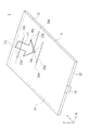
- the image 17 illustrated in FIG. 1 is a three-dimensional image drawn with lines, and the lines that draw the image 17 are formed by a collection of a plurality of convergence points P respectively corresponding to the light converging unit 15.
- the display device 1 forms an image 17 as a three-dimensional image by forming an image of light emitted from the emission surface 13.
- the image 17 is a stereoscopic image that is recognized in space by the viewer.
- the stereoscopic image described in the present application refers to an image 17 that is recognized outside the display device 1 so as to be at a position different from the exit surface 13.
- the stereoscopic image includes not only a three-dimensional image but also a two-dimensional image that is recognized at a position distant from the emission surface 13 of the display device 1, for example.
- the term “stereoscopic image” as used herein refers not only to the image 17 recognized as a three-dimensional shape, but also to the concept including the two-dimensional shape image 17 recognized at a different position from the exit surface 13 of the display device 1. It shows an image 17 that is visually recognized as if it protruded from the light guide plate 11 of the display device 1.
- the light guided by the light guide plate 11 has directivity in the direction connecting each position in the light guide plate 11 and the light source 10, and spreads perpendicular to the direction connecting each position in the light guide plate 11 and the light source 10. Does not have.
- the light guided by the light guide plate 11 has directivity in the Y-axis direction at the position where the light converging part 15 is provided. , Does not have a spread in the X-axis direction. Therefore, for example, on a plane that includes the convergence point P and is parallel to the XZ plane, the light from the light converging unit 15 substantially converges to one convergence point P.
- the light from the light converging unit 15 converges on a convergence line including the convergence point P in space along the Y axis.
- the light from the light converging unit 15 converges to the convergence point P by paying attention to the convergence of the light in the XZ plane as appropriate.
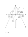
- FIGS. 2 and 3 are conceptual diagrams schematically illustrating the outline of the cross section and the optical path of the display device 1 according to the present invention.
- FIG. 2 shows a cross section parallel to the YZ plane
- FIG. 3 shows a cross section parallel to the XZ plane together with an image 17 visually recognized by an observer.
- 2 and 3 show an example in which an image 17 simulating an arrow that spreads not only on the exit surface 13 side (Z-axis positive direction) of the light guide plate 11 but also on the back surface 14 side (Z-axis negative direction) is shown. Yes.
- the image 17 simulating an arrow is visually recognized such that the front part of the arrow protrudes from the emission surface 13 side and the rear part of the arrow protrudes from the back surface 14 side.
- the light source 10 is attached to the light incident end surface 12 of the light guide plate 11, and the light incident end surface 12 and the light exit surface 13 are substantially orthogonal to each other.
- the surface facing the emission surface 13 is a back surface 14, and the back surface 14 is also substantially orthogonal to the light incident end surface 12.
- the back surface 14 includes a flat surface that is substantially parallel to the emission surface 13 and an inclined surface that forms the reflecting surface 150 (150x, 150y) of the light converging portion 15 (15x, 15y).
- the flat surface of the back surface 14 has a function of guiding the light incident on the light guide plate 11 from the light incident end surface 12 together with the light exit end surface 12 while totally reflecting the light, and spreading the light in the light guide plate 11 into a planar shape. ing.
- the inclined reflecting surface 150 of the light converging unit 15 reflects the light incident on the light guide plate 11 and changes the optical path toward the exit surface 13.
- the plurality of light converging portions 15x (light converging portions 15x1, 15x2, 15x3,...) Located on one line 16 include reflecting surfaces 150x1, 150x2, 150x3,. .
- wire 16 contains reflective surface 150y1, 150y2, 150y3, ..., respectively.
- the inclinations of the reflecting surface 150y2 of the light converging portion 15y2 and the reflecting surface 150y3 of the light converging portion 15y2 described in parentheses in FIG. 3 are opposite to those in FIG. 3 and are inclined toward the end side of the light guide plate 11. To do.
- the reflective surfaces 150x such as the reflective surfaces 150x1, 150x2, 150x3,... Reflect the light from the light source 10 in the direction along the straight line connecting the point on each reflective surface 150x and the convergence point P1.
- the light rays reflected by the reflecting surfaces 150x converge at the convergence point P1.
- the plurality of reflecting surfaces 150x included in each of the light converging portions 15x reflect the light incident from the light source 10 in a direction along a straight line connecting the point on each reflecting surface 150x and the convergence point P1.
- the display device 1 can provide light that travels from the convergence point P1 to any position within the range from the position V2 through the position V1 to the position V3.
- Such a convergence point P1 forms an image 17 that is recognized as if it has protruded to the exit surface 13 side.
- the reflecting surfaces 150y such as the reflecting surfaces 150y1, 150y2, 150y3,... Reflect the light incident from the light source 10 in the direction along the straight line connecting the point on the reflecting surface 150y and the convergence point P2.
- the extended lines of the respective light beams converge at the convergence point P2.
- the plurality of reflecting surfaces 150y included in each of the light converging portions 15y reflect light incident from the light source 10 in a direction along a straight line connecting the point on each reflecting surface 150 and the convergence point P2. .
- the display device 1 can provide light traveling from the convergence point P2 to any position within the range from the position V2 through the position V1 to the position V3.
- Such a convergence point P ⁇ b> 2 forms an image 17 that is recognized as if it has protruded to the opposite side (back surface 14 side) of the exit surface 13.
- the light guide plate 11 has a plurality of light converging portions 15 having convergence points P that are different from each other, and a three-dimensional image is obtained by a collection of a plurality of convergence points P including the convergence points P1 and P2.
- an image 17 can be formed. That is, the light guide plate 11 changes the path of the incident light to the exit surface 13 side, and exits in a direction that converges at the external convergence point P1 or the convergence line, or a direction that diverges from the external convergence point P2 or the convergence line.
- a plurality of light converging units 15 for image formation outside are provided.
- the display device 1 can form an image 17 outside the light guide plate 11 as a three-dimensional image that can be visually recognized by an observer by a plurality of convergence points P or a collection of convergence lines.
- the light guide plate 11 into which the light emitted from the light source 10 enters guides light in a plane parallel to the emission surface 13.
- a plurality of light converging portions 15 having a length in a direction (X axis direction) perpendicular to the light guide direction (Y axis direction) of the light guide plate 11 is formed in a plane parallel to the emission surface 13.
- the normal direction projected onto a plane parallel to the exit surface 13 changes continuously or intermittently along the length direction (X-axis direction) of each light converging unit 15.
- the light guided by the light guide plate 11 is substantially converged to one convergence point P or convergence line in the space by being reflected by the optical surface, or substantially from one convergence point P or convergence line in the space. Is emitted from the emission surface 13 as emitted light in the direction of divergence.
- the convergence point P or the convergence line is different between each of the plurality of light converging units 15 having different positions on the Y axis, and an image 17 is formed in the space by the collection of the plurality of convergence points P or the convergence lines.
- a three-dimensional image that is visually recognized so as to jump out on both the exit surface 13 side and the back surface 14 side will be explained.
- a stereoscopic image that is visually recognized so as to protrude only from the surface on one side may be formed.
- the reflection surface 150 is formed as the light converging unit 15, but various light converging units 15 may be provided as long as the light guide plate 11 can change the path of the incident light.
- the light converging portion 15 may be formed of a cylindrical type or other type of Furnell lens, and the path of incident light may be changed by the refraction action of the refracting surface (prism surface) of the Furnell lens.
- the fullnel lens may be configured by a plurality of portions each having a gap. It is also possible to form the light converging portion 15 with a diffraction grating and change the path of the incident light by the diffraction action. Furthermore, the path of the incident light can be changed by the reflection or refraction action of the prism.
- the distances between all the convergence points P and the exit surface 13 are not constant, for example, when forming an image 17 that spreads in three dimensions, or a two-dimensional image included in a plane oblique to the exit surface 13. 17 is formed such that the density of the converged light increases as the distance from the emission surface 13 increases. Thereby, the blur generated in the formed image 17 becomes substantially constant, and it is possible to form the image 17 that does not cause a viewer to feel uncomfortable.
- the light emitted from the light source 10 has entered the light guide plate 11 from the light incident end surface 12 which is the surface on the one end side in the longitudinal direction of the light guide plate 11, it is not limited to this.
- the back surface 14 is a light incident surface and light is incident from the back surface 14.
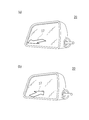
- FIG. 4 is a schematic perspective view showing an example of the appearance of the mirror unit according to the present invention and an image 17 to be displayed.
- FIG. 4 shows a mirror unit 20 mounted as a door mirror of a vehicle 2 such as a passenger car (see FIG. 5).
- the mirror unit 20 illustrated in FIG. 4 includes a display device 1 in which two light guide plates 11 that form light so that different images 17 are displayed are superimposed.
- the displayed image 17 is a three-dimensional image showing the direction of an arrow or the like
- FIG. 4A shows the image 17 showing the rear of the vehicle 2
- each image 17 is displayed as a three-dimensional image of an arrow that protrudes from the mirror surface of the mirror unit 20 and indicates the front or rear of the vehicle 2.
- the arrow is displayed so that the tip of the arrow goes up and down even if it is an arrow indicating front and back.
- the mirror unit 20 provided with the display device 1 according to the present invention can form a stereoscopic image having a spread in a direction other than the direction parallel to the mirror surface. Can be displayed.
- the driver of the vehicle 2 who is an observer of the displayed image 17 is shorter in recognizing the front-rear direction from the front-rear direction arrow than in the case of recognizing the front-rear direction from the up-down direction arrow. It is assumed that recognition in time is possible. Therefore, the mirror unit 20 according to the present invention provides excellent effects such as that the driver can recognize information in a short time during driving.
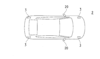
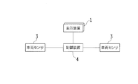
- FIG. 5 is a schematic plan view showing an example of an in-vehicle system to which the mirror unit 20 according to the present invention is applied.
- FIG. 5 shows from above the vehicle 2 in which the mirror unit 20 according to the present invention is applied to an in-vehicle system.
- the vehicle 2 includes vehicle sensors 3 at the front left end, the front right end, the rear left end, and the rear right end, and the vehicle sensor 3 can detect the approach of the vehicle as a detection object outside the vehicle.
- vehicle sensor 3 various objects that may collide with a person, an obstacle, and the like can be used as detection objects.
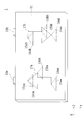
- FIG. 6 is a block diagram schematically showing an example of a control configuration of an in-vehicle system to which the mirror unit 20 according to the present invention is applied.
- the vehicle 2 includes a control device 4 such as an electronic control device (ECU: Electric Control Unit) that controls the display device 1 included in the mirror unit 20, and the control device 4 is arranged at the front left end and the rear left end of the vehicle 2. It is connected to the vehicle sensor 3 provided.
- the vehicle sensor 3 transmits a detection signal to the control device 4 when detecting a detection object such as a nearby vehicle.
- the control device 4 manages the front and rear vehicle sensors 3 and the light sources 10 attached to the two light guide plates 11 included in the display device 1 in advance in association with each other, and receives a detection signal from the vehicle sensor 3, A light emission command signal is transmitted to the light source 10 associated in advance with the vehicle sensor 3 of the transmission source.
- the light source 10 that has received the light emission command signal emits light, and the light guide plate 11 to which the emitted light source 10 is attached displays an image 17 of an arrow indicating the direction. In this way, the mirror unit 20 displays an arrow image 17 indicating the front when the vehicle is detected forward, and displays an arrow image 17 indicating the rear when the vehicle is detected rearward.
- the mirror unit 20 that can be mounted on such an in-vehicle system and can display a plurality of three-dimensional images can be realized in various forms.
- embodiments of various internal structures for realizing the mirror unit 20 will be described.
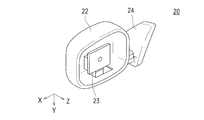
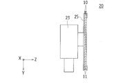
- FIG. 7 is a schematic perspective view schematically showing a part of the internal structure of the mirror unit 20 according to the first embodiment of the present invention.
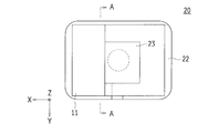
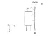
- FIG. 8 is a schematic front view schematically showing an example of the internal structure of the mirror unit 20 according to the first embodiment of the present invention.
- FIG. 9 is a schematic cross-sectional view schematically showing an example of the internal structure of the mirror unit 20 according to the first embodiment of the present invention.
- FIG. 10 is a schematic cross-sectional view showing an example of the internal structure of the mirror member 21 provided in the mirror unit 20 according to the first embodiment of the present invention.
- FIG. 7 shows a state in which a part of the display device 1 serving as a mirror, the mirror member 21 and the like are removed from the mirror unit 20 so that the inside can be visually recognized.
- the direction in which the mirror member 21 is disposed will be described as the front surface. Since the display device 1 emits light toward the front of the mirror member 21, the front of the mirror member 21 is the positive direction of the Z axis.
- 8 is a front view showing the internal structure of the mirror unit 20 through the mirror member 21, and FIGS. 9 and 10 show the internal structure of the mirror unit 20 by a cross-sectional view in the AA direction of FIG. ing.
- FIG. 9 shows the arrangement in the mirror unit 20, and FIG. 10 shows the configuration of members such as the light guide plate 11 and the mirror member 21 in an enlarged manner.
- the mirror unit 20 includes a housing 22 that houses various members such as the display device 1 and the mirror member 21.
- the front surface of the housing 22 is open, and the opening of the housing 22 is closed in a state where the mirror member 21 is loosely fitted with a gap at the edge.
- the housing 22 includes a drive mechanism 23 that can change the angle of the mirror member 21, and the mirror member 21 is fixed to the drive mechanism 23.
- the housing 22 is attached to the vehicle 2 by an attachment portion 24. Inside the attachment portion 24, various electrical components such as the light source 10 and the drive mechanism 23 of the display device 1 in the mirror unit 20 and the interior of the vehicle 2 are provided. Various communication lines for connecting the units such as the control device 4 are connected. Then, the driver can adjust the angle of the mirror member 21 by driving the drive mechanism 23 by operating various operation buttons disposed in the vicinity of the driver's seat.
- a frame is formed, and a fixed frame 25 for fixing the light guide plate 11 and the mirror member 21 to the drive mechanism 23 is disposed.
- the light guide plate 11 and the mirror member 21 housed in the fixed frame 25 are arranged.
- the opening on the front surface of the housing 22 is blocked.
- the fixed frame 25 has a fixed plate on the rear side, and the fixed light guide plate 11 and the mirror member 21 are fixed to the drive mechanism 23 by fixing the fixed plate to the drive mechanism 23.
- two light sources 10 of the display device 1 are disposed behind the drive mechanism 23, and two thin-film light guide plates 11 having flexibility attached to the respective light sources 10. Is inserted into the fixed frame 25 of the mirror member 21 from above.
- the front end of each light guide plate 11 reaches the lower part of the fixed frame 25.
- the light guide plate 11 is disposed on the side of the mirror member 21 through the side of the drive mechanism 23 so that the operation of the drive mechanism 23 is not affected.
- the two light guide plates 11 are arranged behind the mirror member 21.
- the mirror member 21 and the light guide plate 11 are bonded and fixed to the fixed plate with an adhesive as necessary.
- the mirror member 21 is formed on a light transmitting part 21b having a front surface 21a through which light enters and a surface on the rear side of the light transmitting part 21b, and the light that enters from the surface 21a and passes through the light transmitting part 21b is a surface.
- a reflective layer 21c that reflects toward the 21a side.
- the translucent portion 21b is formed using a material such as a transparent polycarbonate resin, a resin material such as polymethyl methacrylate resin, or an inorganic material such as glass.
- the reflective layer 21c is a layer such as a plating layer or a vapor deposition film formed by a method such as plating or vapor deposition using a metal such as aluminum or silver. And the mirror member 21 functions as a mirror because the light which approached from the surface 21a of the mirror member 21 reflects in the reflective layer 21c.
- the mirror unit 20 is formed by stacking the two light guide plates 11 behind the mirror member 21. More specifically, the mirror member 21 and the two light guide plates 11 behind the mirror member 21 are superposed so that their planar portions are parallel to each other. That is, the mirror member 21 has a book-plate shape, and is formed on the light transmitting portion 21b whose one surface is the front surface 21a and the rear surface that is the other surface of the light transmitting portion 21b, and enters from the surface 21a. And a reflection layer 21c that reflects the light transmitted through the light transmitting portion 21b toward the surface 21a.
- the plurality of light guide plates 11 are superposed on the other surface side of the mirror member 21.
- the mirror member 21 and the two light guide plates 11 behind the mirror member 21 are arranged so as to overlap each other so that the respective planar portions are parallel to each other. It can be transformed into various forms.
- FIG. 11 is a schematic cross-sectional view schematically showing an example of the internal structure of the mirror unit 20 according to the first embodiment of the present invention.
- FIG. 11 is a schematic cross-sectional view illustrating one modification of the mirror unit 20 according to the first embodiment.
- the two light sources 10 of the display device 1 are arranged on the upper part of the mirror member 21, the light guide plates 11 extending downward are attached to the respective light sources 10, and the light guide plate 11 is positioned behind the mirror member 21. It is the form arranged so as to.
- the light guide plate 11 may be formed of a hard material having no flexibility.
- FIG. 12 is a schematic diagram illustrating an example of an optical path related to the display device 1 included in the mirror unit 20 according to the first embodiment of the present invention.
- FIG. 12 is a schematic cross-sectional view of the display device 1 according to the first embodiment, and shows the path of light emitted from the light source 10 with a solid line and an alternate long and short dash line with arrows, and external light entering from the outside. The course is indicated by a double line with an arrow.
- the light emitted from the light source 10 enters the light guide plate 11 from above.
- the light guide plate 11 guides light incident from the light source 10 while repeating total reflection between the output surface 13 and the back surface 14, reflects the light by the light converging unit 15 (not shown in FIG. 12), and outputs the light from the output surface 13. .
- the light emitted from the exit surface 13 of the light guide plate 11 passes through the mirror member 21 and forms an image outside the mirror unit 20 to form a three-dimensional image indicating the direction of an arrow or the like.
- the light emitted from the light guide plate 11 disposed at the rear indicated by the alternate long and short dash line passes through the other light guide plate 11 superimposed on the front, and further passes through the mirror member 21.
- the mirror member 21 functions as a mirror by entering the light through the surface 21a from the outside and transmitting the light transmitted through the light transmitting portion 21b through the surface 21a and reflecting the light through the reflective layer 21c.
- the reflected image 17 is not distorted when functioning as a mirror.
- Embodiment comprised as mentioned above uses the display apparatus 1 provided with the two light-guide plates 11 for the mirror unit 20, and uses the three-dimensional image according to the signal from the outside, ie, another vehicle which approaches It is possible to display an arrow indicating a direction corresponding to the position of an obstacle such as forward or rearward as an actual direction. Further, since the mirror member 21 housed in the mirror unit 20 is disposed in front of the light guide plate 11, the image 17 reflected by the mirror member 21 causes a phenomenon such as distortion due to the influence of the light guide plate 11. There is no.
- 2nd Embodiment is the form which replaced the position of the light-guide plate 11 with which the mirror unit 20 is provided, and the mirror member 21 in 1st Embodiment.
- the first embodiment since the configuration other than the positions of the light guide plate 11 and the mirror member 21 is the same as that of the first embodiment, the first embodiment is referred to for the other configurations. The description is omitted.
- components similar to those in the first embodiment are denoted by the same reference numerals as those in the first embodiment.
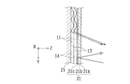
- FIG. 13 is a schematic cross-sectional view schematically showing an example of the internal structure of the mirror unit 20 according to the second embodiment of the present invention.
- the housing 22 two light sources 10 of the display device 1 are disposed behind the drive mechanism 23, and two flexible sheets attached to the respective light sources 10 are provided.
- a thin-film light guide plate 11 is inserted into the fixed frame 25 from above. The front end of each light guide plate 11 reaches the lower part of the fixed frame 25. Further, the light guide plate 11 is disposed on the side of the mirror member 21 through the side of the drive mechanism 23 so that the operation of the drive mechanism 23 is not affected.
- the two light guide plates 11 are arranged in front of the mirror member 21.
- the two light guide plates 11 are stacked in front of the mirror member 21. More specifically, the mirror member 21 and the two light guide plates 11 in front of the mirror member 21 are arranged so as to be parallel to each other. That is, the mirror member 21 has a book-plate shape, and is formed on the light transmitting portion 21b whose one surface is the front surface 21a and the rear surface that is the other surface of the light transmitting portion 21b, and enters from the surface 21a. And a reflection layer 21c that reflects the light transmitted through the light transmitting portion 21b toward the surface 21a.
- the plurality of light guide plates 11 are arranged so that the surface 21a of the mirror member 21 overlaps the light reflecting side.
- the mirror member 21 and the two light guide plates 11 in front of the mirror member 21 are arranged so as to be parallel to each other, Various modifications are possible.
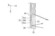
- FIG. 14 is a schematic cross-sectional view schematically showing an example of the internal structure of the mirror unit 20 according to the second embodiment of the present invention.
- FIG. 14 is a schematic cross-sectional view illustrating one modification of the mirror unit 20 according to the second embodiment.
- the two light sources 10 of the display device 1 are arranged on the upper part of the mirror member 21, the light guide plates 11 extending downward are attached to the respective light sources 10, and the light guide plate 11 is positioned in front of the mirror member 21. It is the form arranged so as to. When realizing in such a form, the light guide plate 11 may be formed of a hard material having no flexibility.
- FIG. 15 is a schematic diagram illustrating an example of an optical path related to the display device 1 included in the mirror unit 20 according to the second embodiment of the present invention.
- FIG. 15 is a schematic cross-sectional view of the display device 1 according to the second embodiment, and shows the path of light emitted from the light source 10 with a solid line and an alternate long and short dash line with arrows. The course is indicated by a double line with an arrow. The light emitted from the light source 10 enters the light guide plate 11 from above.
- the light guide plate 11 guides light incident from the light source 10 while repeating total reflection between the output surface 13 and the back surface 14, reflects the light by the light converging unit 15, and outputs the light from the output surface 13.
- the light emitted from the emission surface 13 of the light guide plate 11 forms an image outside the mirror unit 20 to form a three-dimensional image indicating the direction of an arrow or the like.
- the light emitted from the rear light guide plate 11 is transmitted through the other light guide plate 11 superimposed on the front and forms an image outside the mirror unit 20. Since the image 17 displayed by the image formation does not need to pass through the reflection layer 21c of the mirror member 21, the display device 1 according to the second embodiment can display the bright image 17. .
- the mirror member 21 is transmitted through the two light guide plates 11 from the outside, further enters through the surface 21a, and reflects the light transmitted through the light transmitting portion 21b to the surface 21a side by the reflection layer 21c. By passing through one light guide plate 11 and emitting it to the outside, it functions as a mirror.
- the light reflected by the mirror member 21 is transmitted through the light guide plate 11, but the area of the reflecting surface of the light converging portion 15 is smaller than the area of the surface 21a (the number of reflecting surfaces is reduced). By doing so, it is possible to suppress the distortion of the image reflected while functioning as a mirror to such an extent that the observer cannot recognize it.
- 2nd Embodiment comprised as mentioned above uses the display apparatus 1 provided with the two light-guide plates 11 for the mirror unit 20, and the three-dimensional image according to the signal from the outside, ie, another vehicle which approaches It is possible to display an arrow indicating a direction corresponding to the position of an obstacle such as forward or rearward as an actual direction. Further, since the light guide plate 11 housed in the mirror unit 20 is disposed in front of the mirror member 21, the image 17 formed by the image formation of the light guide plate 11 can be displayed brightly. Furthermore, by appropriately designing the light converging unit 15 included in the display device 1, it is possible to suppress the distortion of the image reflected when the mirror member 21 functions as a mirror to the extent that the observer cannot recognize it. .
- the light guide plate 11 of the display device 1 provided in the mirror unit 20 is also used as the mirror member 21 in the first embodiment.
- structures other than the light-guide plate 11 and the mirror member 21 are the same as that of 1st Embodiment, it shall refer to 1st Embodiment about other structures, The description Is omitted.
- components similar to those in the first embodiment are denoted by the same reference numerals as those in the first embodiment.
- FIG. 16 is a schematic cross-sectional view schematically showing an example of the internal structure of the mirror unit 20 according to the third embodiment of the present invention.
- FIG. 17 shows the mirror unit 20 according to the third embodiment of the present invention. It is a schematic diagram which shows the example of the optical path regarding the display apparatus 1 with which FIG. FIG. 17 superimposes the schematic cross-sectional view of the display device 1 according to the third embodiment, and shows the path of the light emitted from the light source 10 with a solid line and an alternate long and short dash line with arrows. The course is indicated by a double line with an arrow.
- two light guide plates 11 are inserted from above into a fixed frame 25 fixed to the front surface of the drive mechanism 23, and above each light guide plate 11.
- Each has a light source 10 attached thereto.
- the light guide plate 11 is disposed in a state where it is overlapped in the front-rear direction, the rear light guide plate 11 also has a function as a mirror member, and the dedicated mirror member 21 is not disposed.
- the mirror unit 20 according to the third embodiment of the present invention is superposed so that the respective planar portions of the two light guide plates 11 are in parallel, and no dedicated mirror member 21 is arranged.
- the rear light guide plate 11 uses a metal such as aluminum or silver on the rear surface, and has a plating layer formed by a method such as plating and vapor deposition, and a reflective layer 18 such as a vapor deposition film. For this reason, when outside light enters from the exit surface 13 of the front light guide plate 11, the entered external light is reflected by the reflective layer 18 of the rear light guide plate 11, so that the rear light guide plate 11 serves as a mirror member. Also works.
- the light emitted from the light source 10 enters the light guide plate 11.
- the light guide plate 11 guides light incident from the light source 10 while repeating total reflection between the output surface 13 and the back surface 14, reflects the light by the light converging unit 15, and outputs the light from the output surface 13.
- the light emitted from the emission surface 13 of the light guide plate 11 forms an image outside the mirror unit 20 to form a three-dimensional image indicating the direction of an arrow or the like. That is, the plurality of light guide plates 11 arranged to overlap the display device 1 change the exit surface 13 that emits light incident from the light source 10 and the path of the light incident from the light source 10 to the exit surface 13 side.
- a plurality of light converging sections 15 that are emitted in a direction that converges at a convergence point P or convergence line outside the mirror unit 20 or a direction that diverges from the convergence point P or convergence line outside the mirror unit 20 and forms an image outside.
- each light guide plate 11 can form different three-dimensional images and display images such as arrows indicating directions when the light source 10 emits light.
- the image 17 displayed by the imaging does not transmit the reflection layer 21c of the mirror member 21 as in the second embodiment, and therefore the display device 1 according to the third embodiment displays the bright image 17. It is possible.
- the rear light guide plate 11 is formed on the rear rear surface 14 facing the output surface 13 which is the front surface, and enters from the output surface 13 and passes through the front light guide plate 11 and itself.
- a reflection layer 18 that reflects external light toward the emission surface 13 is provided.
- the external light reflected by the reflective layer 18 is emitted from the emission surface 13, passes through the front light guide plate 11, and is emitted from the emission surface 13 of the front light guide plate 11.
- the rear light guide plate 11 also functions as a mirror.
- the light reflected by the rear light guide plate 11 is transmitted through the front light guide plate 11, but since there is only one light guide plate 11 that is transmitted, compared to the case of transmitting through the two light guide plates 11. However, it is possible to suppress distortion of the reflected image while functioning as a mirror.
- Embodiment comprised as mentioned above uses the display apparatus 1 provided with the two light-guide plates 11 for the mirror unit 20, and the three-dimensional image according to the signal from the outside, ie, another vehicle which approaches It is possible to display an arrow indicating a direction corresponding to the position of an obstacle such as forward or rearward as an actual direction.
- the rear light guide plate 11 is formed with a reflective layer 18 and also functions as a mirror member, the image 17 formed by the image formation of the light guide plate 11 can be displayed brightly. It is.
- the distortion of the image reflected in functioning as a mirror compared with the case where the light is transmitted through the two light guide plates 11. Can be suppressed.
- the fourth embodiment is a form in which a layer for protecting the surface is provided on the rear light guide plate 11 in the third embodiment.
- the third embodiment since the configuration other than the newly provided layer is the same as that of the third embodiment, the third embodiment is referred to for the other configuration, and the description thereof is omitted. .
- components similar to those in the third embodiment are denoted by the same reference numerals as those in the third embodiment.
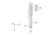
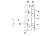
- FIG. 18 is a schematic diagram illustrating an example of an optical path related to the display device 1 included in the mirror unit 20 according to the fourth embodiment of the present invention.
- FIG. 18 superimposes on the schematic cross-sectional view of the display device 1 according to the fourth embodiment, and shows the path of the light emitted from the light source 10 with a solid line and an alternate long and short dash line with arrows. The course is indicated by a double line with an arrow.
- two light guide plates 11 are inserted from above into a fixed frame 25 fixed to the front surface of the drive mechanism 23, and above each light guide plate 11.
- Each has a light source 10 attached thereto.
- the light guide plate 11 is disposed in a state where the light guide plate 11 is overlapped in the front-rear direction, and a layer that protects the rear surface is formed on the rear surface of the rear light guide plate 11.
- the formed layer is a plating layer formed by a method such as plating or vapor deposition using a metal such as aluminum or silver on the light transmitting layer 19 using a resin material such as transparent polycarbonate resin or polymethyl methacrylate resin.
- a reflective layer 18 such as a vapor deposition film is superimposed.
- the translucent layer 19 is integrated with the rear light guide plate 11 by a process such as a heat treatment at a flat part where the light converging part 15 is not formed. For this reason, when external light enters from the exit surface 13 of the light guide plate 11, the light that has entered passes through the two light guide plates 11 that are arranged in a superimposed manner, and further passes through the light transmissive layer 19 to be a reflective layer. Therefore, the protective layer having the light-transmitting layer 19 and the reflective layer 18 functions as a mirror member.
- the light emitted from the light source 10 enters the light guide plate 11 from above.
- the light guide plate 11 guides light incident from the light source 10 while repeating total reflection between the output surface 13 and the back surface 14, reflects the light by the light converging unit 15, and outputs the light from the output surface 13.
- the light emitted from the emission surface 13 of the light guide plate 11 forms an image outside the mirror unit 20 to form a three-dimensional image indicating the direction of an arrow or the like. That is, the plurality of light guide plates 11 arranged to overlap the display device 1 change the exit surface 13 that emits light incident from the light source 10 and the path of the light incident from the light source 10 to the exit surface 13 side.
- a plurality of light converging sections 15 that are emitted in a direction that converges at a convergence point P or convergence line outside the mirror unit 20 or a direction that diverges from the convergence point P or convergence line outside the mirror unit 20 and forms an image outside.
- each light guide plate 11 can form different three-dimensional images and display images such as arrows indicating directions when the light source 10 emits light. Since the image 17 displayed by the imaging does not pass through the reflection layer 21c of the mirror member 21 as in the first embodiment, the display device 1 according to the fourth embodiment displays a bright image 17. It is possible.
- the rear light guide plate 11 is not affected by the reflection layer 18 because the reflection layer 18 is not formed on the light converging portion 15 formed as a notch on the rear surface of the light guide plate 11, for example.
- a bright image 17 can be displayed.
- the light guide plate 11 disposed in the rear in this manner is transmitted through the rear surface 14 on the rear side opposite to the light exit surface 13 and transmits the external light that has passed through the light guide plate 11 that is superimposed from the light exit surface 13.
- the light layer 19 includes a reflective layer 18 that reflects external light transmitted through the light transmissive layer 19 toward the emission surface 13 side. Then, the external light reflected by the reflective layer 18 passes through the light transmissive layer 19, passes through the light guide plate 11 that is superimposed, and exits from the exit surface 13 of the front light guide plate 11. Thereby, the translucent layer 19 also functions as a mirror.
- the fourth embodiment configured as described above uses the display device 1 in which the mirror unit 20 includes the two light guide plates 11, and the light-transmitting layer 19 and the reflective layer 18 are formed on the rear light guide plate 11. It is possible to display a three-dimensional image according to the signal from the outside, that is, an arrow indicating the direction according to the position of an obstacle such as another vehicle approaching forward or rearward as the actual direction. is there. Further, since the light transmissive layer 19 and the reflective layer 18 are formed and also have a function as the mirror member 21, the image 17 formed by the image formation of the light guide plate 11 can be displayed brightly. is there.
- the light guide plate 11 of the display device 1 provided in the mirror unit 20 is a single light guide plate 11 and a plurality of types of images 17 are formed using the single light guide plate 11 in the first embodiment. is there. Since the configuration other than the light guide plate 11 and the light source 10 is the same as that of the first embodiment, the first embodiment is referred to for the other configuration, and the description thereof is omitted. Also in the fifth embodiment, the same reference numerals as those in the first embodiment are assigned to the same configurations as those in the first embodiment.
- FIG. 19 is an explanatory diagram schematically illustrating the display device 1 according to the fifth embodiment of the present invention together with an image formed in a space.
- FIG. 19 schematically shows the display device 1 according to the fifth embodiment.
- the display device 1 according to the fifth embodiment includes a single light guide plate 11, a first light source 10a, and a second light source 10b.
- the light guide plate 11 includes a first light converging part group including a plurality of light converging parts 15 indicated as light converging parts 15aa, 15ba, 15ca,... And a plurality of light converging parts 15ab, 15bb, 15cb,.
- the second light converging part group including the light converging part 15 is formed.
- the light converging portions 15aa, 15ba, 15ca,... are formed along the lines 16aa, 16ba, 16ca,..., Respectively, and the light converging portions 15ab, 15bb, 15cb,. It is formed along.
- the light emitted from the first light source 10a enters the light guide plate 11, and the first light converging unit group including a plurality of light converging units 15 shown as light converging units 15aa, 15ba, 15ca,.
- the optical path is changed, and the first image 17a is formed.
- the light emitted from the second light source 10b enters the light guide plate 11, and the second light converging unit group including a plurality of light converging units 15 shown as light converging units 15ab, 15bb, 15cb,.
- the optical path is changed, and the second image 17b is formed. That is, when the first light source 10a emits light, the first image 17a is displayed, and when the second light source 10b emits light, the second image 17b is displayed.
- the light emitted from the first light source 10a and the second light source 10b is narrowed down so that the directivity becomes strong, for example, the light emitted from the first light source 10a is converted into the second light converging unit group. It can suppress entering into. Further, even if light emitted from the first light source 10a enters the second light converging unit group, it does not form an image in a direction that can be viewed from the driver's seat. be able to. The same applies to the light emitted from the second light source 10b.
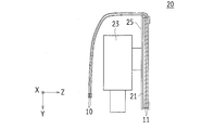
- FIG. 20 is a schematic perspective view showing an example of an appearance and a displayed image of the mirror unit 20 according to the fifth embodiment of the present invention.
- the mirror unit 20 illustrated in FIG. 20 can form light so that different first images 17a and second images 17b are displayed.
- the mirror unit 20 illustrated in FIG. 20 displays a first image 17a indicating a backward arrow when the first light source 10a emits light, and displays a first arrow indicating a forward arrow when the second light source 10b emits light. Two images 17b are displayed.
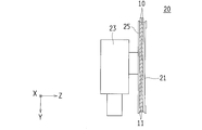
- FIG. 21 is a schematic cross-sectional view schematically showing an example of the internal structure of the mirror unit 20 according to the fifth embodiment of the present invention.
- the mirror unit 20 according to the fifth embodiment is provided with a fixed frame 25 that is fixed to the drive mechanism 23, and the light guide plate 11 and the mirror member 21 are accommodated in the fixed frame 25.
- one light guide plate 11 is disposed behind the mirror member 21, and a first light source 10 a and a second light source 10 b are attached to the top of the light guide plate 11.
- a plurality of light sources 10, here, the first light source 10 a and the second light source 10 b are attached to one light guide plate 11. Yes.
- the light guide plate 11 serves as the light converging unit 15 to change the optical path of the light incident from the first light source 10a and to form the first light 17 so that the first image 17a is displayed.
- a second light converging part group that changes the optical path of the light incident from the second light source 10b and forms the light so that the second image 17b is displayed.
- the sixth embodiment is a form in which the positions of the light guide plate 11 and the mirror member 21 provided in the mirror unit 20 are exchanged in the fifth embodiment.
- the fifth embodiment since the configuration other than the positions of the light guide plate 11 and the mirror member 21 is the same as that of the fifth embodiment, the fifth embodiment is referred to for the other configurations. The description is omitted.
- components similar to those in the fifth embodiment are denoted by the same reference numerals as those in the fifth embodiment.
- FIG. 22 is a schematic cross-sectional view schematically showing an example of the internal structure of the mirror unit 20 according to the sixth embodiment of the present invention.
- the mirror unit 20 according to the sixth embodiment is provided with a fixed frame 25 that is fixed to the drive mechanism 23, and the light guide plate 11 and the mirror member 21 are accommodated in the fixed frame 25.
- a single light guide plate 11 is disposed in front of the mirror member 21, and a first light source 10 a and a second light source 10 b are attached to the top of the light guide plate 11.
- the mirror unit 20 can display a plurality of different images 17 with one light guide plate 11.
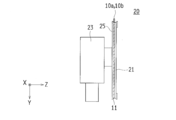
- FIG. 23 is a schematic cross-sectional view schematically showing an example of the internal structure of the mirror unit 20 according to the seventh embodiment of the present invention.
- the mirror unit 20 according to the seventh embodiment is provided with a fixed frame 25 that is fixed to the drive mechanism 23, and the light guide plate 11 is accommodated in the fixed frame 25.
- a first light source 10 a and a second light source 10 b are attached to the upper part of the light guide plate 11.
- the light guide plate 11 also has a function as a mirror member, and no dedicated mirror member 21 is disposed.
- 3rd Embodiment and 4th Embodiment shall be referred and the description is abbreviate
- the mirror unit 20 according to the seventh embodiment of the present invention can display a plurality of different images 17 with one light guide plate 11.
- two light guide plates 11 are used in an overlapping manner.
- the present invention is not limited to this, and only one light guide plate 11 that forms a stereoscopic image is used. It is also possible to use three or more light guide plates 11 and the like, and various forms can be developed.
- the light guide plate 11 that emits light in the direction of the person is arranged.
- a light source 10 that is linked to a turn signal lamp (turn signal lamp) mounted on the vehicle 2 is attached to the light guide plate 11 that emits light in a direction in which the driver of the vehicle behind is an observer. It is configured to emit light when making a left turn and changing course. In this case, since the driver of the vehicle behind is the observer, it is not always necessary to display a three-dimensional image. Therefore, the emitted light is not converged in the light guide plate 11 but in the same direction.
- a reflecting surface may be formed so as to follow a parallel optical path.
- the mirror unit 20 having the light guide plate 11 formed in this way can observe a stereoscopic image indicating a direction from the driver of the vehicle 2 on which it is mounted, and from the driver of the vehicle behind. Can observe the light emission of the mirror member 21 in the direction of changing the course.
- a layer such as the light transmitting layer 19 and the reflective layer 18 may be formed on the rear surface of the other light guide plate 11.
- the fifth to seventh embodiments it is possible to provide three or more light sources 10 and display three or more images, and to provide a plurality of images with a plurality of light sources 10. It is also possible to use a plurality of light guide plates 11 that display the image.
- the present invention is not limited to this, and can be mounted on various mirrors such as a rearview mirror in a vehicle.
- the form in which the arrow indicating the direction is displayed is shown.
- the present invention is not limited to this, and the image 17 indicating the direction by a method other than the arrow, and the image 17 indicating the information other than the direction are further displayed. It can be expanded into various forms such as display.
- Display device 10 10a, 10b Light source 11
- Light guide plate (light guide member) 12 Light entrance end face 13
- Light exit face 15 (15a, 15b, ..., 15x1, ..., 15y3, 15aa, ..., 15ba, ...)
- Reflective layer 19 Translucent layer 2 Vehicle 20
- Mirror unit 21 21a Surface 21b Translucent portion 21c Reflective layer 3
Landscapes
- Engineering & Computer Science (AREA)
- Mechanical Engineering (AREA)
- Physics & Mathematics (AREA)
- General Physics & Mathematics (AREA)
- Theoretical Computer Science (AREA)
- Multimedia (AREA)
- Business, Economics & Management (AREA)
- Accounting & Taxation (AREA)
- Marketing (AREA)
- Geometry (AREA)
- Human Computer Interaction (AREA)
- Lighting Device Outwards From Vehicle And Optical Signal (AREA)
- Rear-View Mirror Devices That Are Mounted On The Exterior Of The Vehicle (AREA)
- Illuminated Signs And Luminous Advertising (AREA)
- Planar Illumination Modules (AREA)
- Optical Elements Other Than Lenses (AREA)
- Instrument Panels (AREA)
Priority Applications (3)
| Application Number | Priority Date | Filing Date | Title |
|---|---|---|---|
| CN201680034210.XA CN107709097B (zh) | 2015-09-04 | 2016-08-11 | 反射镜单元和显示装置 |
| DE112016004016.4T DE112016004016B4 (de) | 2015-09-04 | 2016-08-11 | Spiegeleinheit und Display-Vorrichtung |
| US15/850,706 US20180137791A1 (en) | 2015-09-04 | 2017-12-21 | Mirror unit and display device |
Applications Claiming Priority (2)
| Application Number | Priority Date | Filing Date | Title |
|---|---|---|---|
| JP2015-174796 | 2015-09-04 | ||
| JP2015174796A JP6610099B2 (ja) | 2015-09-04 | 2015-09-04 | ミラーユニット及び表示装置 |
Related Child Applications (1)
| Application Number | Title | Priority Date | Filing Date |
|---|---|---|---|
| US15/850,706 Continuation US20180137791A1 (en) | 2015-09-04 | 2017-12-21 | Mirror unit and display device |
Publications (1)
| Publication Number | Publication Date |
|---|---|
| WO2017038426A1 true WO2017038426A1 (ja) | 2017-03-09 |
Family
ID=58187442
Family Applications (1)
| Application Number | Title | Priority Date | Filing Date |
|---|---|---|---|
| PCT/JP2016/073688 Ceased WO2017038426A1 (ja) | 2015-09-04 | 2016-08-11 | ミラーユニット及び表示装置 |
Country Status (6)
| Country | Link |
|---|---|
| US (1) | US20180137791A1 (enExample) |
| JP (1) | JP6610099B2 (enExample) |
| CN (1) | CN107709097B (enExample) |
| DE (1) | DE112016004016B4 (enExample) |
| TW (1) | TW201711877A (enExample) |
| WO (1) | WO2017038426A1 (enExample) |
Cited By (2)
| Publication number | Priority date | Publication date | Assignee | Title |
|---|---|---|---|---|
| WO2020138367A1 (ja) * | 2018-12-26 | 2020-07-02 | 市光工業株式会社 | 車両用ミラー装置、及び照光可能なミラー表示デバイス |
| WO2020241862A1 (ja) * | 2019-05-30 | 2020-12-03 | 京セラ株式会社 | 表示装置及び移動体 |
Families Citing this family (9)
| Publication number | Priority date | Publication date | Assignee | Title |
|---|---|---|---|---|
| US10406973B2 (en) * | 2016-02-01 | 2019-09-10 | Irvin Automotive Products, LLC | Lighted auto visor mirror |
| JP6939577B2 (ja) * | 2017-06-22 | 2021-09-22 | オムロン株式会社 | 車両用発光装置 |
| CN109114517A (zh) * | 2017-06-22 | 2019-01-01 | 欧姆龙株式会社 | 车辆用发光装置 |
| JP6590299B2 (ja) * | 2017-10-03 | 2019-10-16 | マツダ株式会社 | 運転支援装置 |
| JP6881346B2 (ja) * | 2018-02-14 | 2021-06-02 | オムロン株式会社 | 導光板、車両用灯具 |
| WO2020080133A1 (ja) | 2018-10-16 | 2020-04-23 | 株式会社小糸製作所 | 車両用装置 |
| DE112019007095T5 (de) * | 2019-03-28 | 2022-01-05 | Honda Motor Co., Ltd. | Sattelaufsitzfahrzeug |
| JP7434876B2 (ja) * | 2019-12-19 | 2024-02-21 | オムロン株式会社 | 導光板、表示装置、入力装置および電気機器 |
| JP7493426B2 (ja) * | 2020-10-14 | 2024-05-31 | 株式会社ペンストン | 車両用警告装置 |
Citations (8)
| Publication number | Priority date | Publication date | Assignee | Title |
|---|---|---|---|---|
| JPH01502458A (ja) * | 1987-01-06 | 1989-08-24 | ヒユーズ・エアクラフト・カンパニー | 薄型パネルホログラフディスプレイシステム |
| JP2002539026A (ja) * | 1999-03-15 | 2002-11-19 | ジェンテクス・コーポレーション | 半導体発光エミッタパッケージを使用するインジケータ及び照明器 |
| JP3104914U (ja) * | 2004-04-28 | 2004-10-21 | 仁▲喜▼ 翁 | 自動車及びオートバイのパターン表示装置 |
| JP2007523004A (ja) * | 2004-02-23 | 2007-08-16 | ケー.ダブリュー. マス カンパニー, インク. | 信号組立体 |
| JP2007334566A (ja) * | 2006-06-14 | 2007-12-27 | Honda Motor Co Ltd | 運転支援装置 |
| JP2009083631A (ja) * | 2007-09-28 | 2009-04-23 | Murakami Corp | 車両用後写鏡 |
| WO2012112536A2 (en) * | 2011-02-14 | 2012-08-23 | Gentex Corporation | Low profile optical lighting assembly for use in outside vehicle mirror and method of forming same |
| JP2014234022A (ja) * | 2013-05-31 | 2014-12-15 | サカエ理研工業株式会社 | ドアミラーユニット |
Family Cites Families (7)
| Publication number | Priority date | Publication date | Assignee | Title |
|---|---|---|---|---|
| US7370983B2 (en) * | 2000-03-02 | 2008-05-13 | Donnelly Corporation | Interior mirror assembly with display |
| JP2007127871A (ja) * | 2005-11-04 | 2007-05-24 | Alps Electric Co Ltd | 立体表示装置 |
| DE502007004000D1 (de) | 2007-03-14 | 2010-07-15 | Smr Patents Sarl | Rückblickspiegel für Fahrzeuge, vorzugsweise für Kraftfahrzeuge |
| US8287164B2 (en) | 2008-09-15 | 2012-10-16 | Gentex Corporation | Outside mirror lighting assembly and method of forming same |
| JP5649936B2 (ja) * | 2010-12-02 | 2015-01-07 | スタンレー電気株式会社 | 画像表示装置 |
| EP2463154B1 (de) | 2010-12-10 | 2016-03-23 | SMR Patents S.à.r.l. | Leuchtanzeige hinter dem Spiegelglas eines Außenspiegel eines Fahrzeugs |
| JP6248473B2 (ja) * | 2013-08-28 | 2017-12-20 | 日本精機株式会社 | ヘッドアップディスプレイ装置 |
-
2015
- 2015-09-04 JP JP2015174796A patent/JP6610099B2/ja active Active
-
2016
- 2016-08-11 WO PCT/JP2016/073688 patent/WO2017038426A1/ja not_active Ceased
- 2016-08-11 DE DE112016004016.4T patent/DE112016004016B4/de active Active
- 2016-08-11 CN CN201680034210.XA patent/CN107709097B/zh active Active
- 2016-08-26 TW TW105127337A patent/TW201711877A/zh unknown
-
2017
- 2017-12-21 US US15/850,706 patent/US20180137791A1/en not_active Abandoned
Patent Citations (8)
| Publication number | Priority date | Publication date | Assignee | Title |
|---|---|---|---|---|
| JPH01502458A (ja) * | 1987-01-06 | 1989-08-24 | ヒユーズ・エアクラフト・カンパニー | 薄型パネルホログラフディスプレイシステム |
| JP2002539026A (ja) * | 1999-03-15 | 2002-11-19 | ジェンテクス・コーポレーション | 半導体発光エミッタパッケージを使用するインジケータ及び照明器 |
| JP2007523004A (ja) * | 2004-02-23 | 2007-08-16 | ケー.ダブリュー. マス カンパニー, インク. | 信号組立体 |
| JP3104914U (ja) * | 2004-04-28 | 2004-10-21 | 仁▲喜▼ 翁 | 自動車及びオートバイのパターン表示装置 |
| JP2007334566A (ja) * | 2006-06-14 | 2007-12-27 | Honda Motor Co Ltd | 運転支援装置 |
| JP2009083631A (ja) * | 2007-09-28 | 2009-04-23 | Murakami Corp | 車両用後写鏡 |
| WO2012112536A2 (en) * | 2011-02-14 | 2012-08-23 | Gentex Corporation | Low profile optical lighting assembly for use in outside vehicle mirror and method of forming same |
| JP2014234022A (ja) * | 2013-05-31 | 2014-12-15 | サカエ理研工業株式会社 | ドアミラーユニット |
Cited By (7)
| Publication number | Priority date | Publication date | Assignee | Title |
|---|---|---|---|---|
| WO2020138367A1 (ja) * | 2018-12-26 | 2020-07-02 | 市光工業株式会社 | 車両用ミラー装置、及び照光可能なミラー表示デバイス |
| JPWO2020138367A1 (ja) * | 2018-12-26 | 2021-11-11 | 市光工業株式会社 | 車両用ミラー装置、及び照光可能なミラー表示デバイス |
| US11453341B2 (en) | 2018-12-26 | 2022-09-27 | Ichikoh Industries, Ltd. | Vehicle mirror device and illuminatable mirror display device |
| JP7397003B2 (ja) | 2018-12-26 | 2023-12-12 | 美里工業株式会社 | 車両用ミラー装置、照光デバイス、車両用ミラー表示アセンブリ及び車両のミラー |
| WO2020241862A1 (ja) * | 2019-05-30 | 2020-12-03 | 京セラ株式会社 | 表示装置及び移動体 |
| JPWO2020241862A1 (enExample) * | 2019-05-30 | 2020-12-03 | ||
| JP7208378B2 (ja) | 2019-05-30 | 2023-01-18 | 京セラ株式会社 | 表示装置及び移動体 |
Also Published As
| Publication number | Publication date |
|---|---|
| DE112016004016T5 (de) | 2018-05-24 |
| US20180137791A1 (en) | 2018-05-17 |
| JP6610099B2 (ja) | 2019-11-27 |
| DE112016004016B4 (de) | 2022-01-05 |
| CN107709097B (zh) | 2020-05-22 |
| JP2017047850A (ja) | 2017-03-09 |
| TW201711877A (zh) | 2017-04-01 |
| CN107709097A (zh) | 2018-02-16 |
Similar Documents
| Publication | Publication Date | Title |
|---|---|---|
| JP6610099B2 (ja) | ミラーユニット及び表示装置 | |
| US11493758B2 (en) | Display device, in particular for vehicle, and vehicle having display device with volume hologram | |
| JP6551068B2 (ja) | 表示装置 | |
| JP6866738B2 (ja) | 画像表示ユニット | |
| JP6651750B2 (ja) | 車両用表示装置 | |
| US9891433B2 (en) | Virtual image generation device and head-up display | |
| WO2015159523A1 (ja) | ヘッドアップディスプレイ、およびヘッドアップディスプレイを搭載した移動体 | |
| CN107710054B (zh) | 显示装置 | |
| WO2015159521A1 (ja) | ヘッドアップディスプレイ、およびヘッドアップディスプレイを搭載した移動体 | |
| CN113375119B (zh) | 车辆用发光装置 | |
| US10981581B2 (en) | Display device | |
| JP6510578B2 (ja) | ヘッドアップディスプレイ装置 | |
| JP2018081276A (ja) | 虚像表示装置 | |
| US20190082167A1 (en) | Alert display system | |
| JP2019009100A (ja) | 車両用発光装置 | |
| JP2018176991A (ja) | 車両用座席及び画像表示ユニット | |
| JP2018180262A (ja) | 車両用画像表示ユニット |
Legal Events
| Date | Code | Title | Description |
|---|---|---|---|
| 121 | Ep: the epo has been informed by wipo that ep was designated in this application |
Ref document number: 16841458 Country of ref document: EP Kind code of ref document: A1 |
|
| WWE | Wipo information: entry into national phase |
Ref document number: 112016004016 Country of ref document: DE |
|
| 122 | Ep: pct application non-entry in european phase |
Ref document number: 16841458 Country of ref document: EP Kind code of ref document: A1 |