WO2017033516A1 - Dispositif et procédé d'aide à l'interprétation de radiographies - Google Patents
Dispositif et procédé d'aide à l'interprétation de radiographies Download PDFInfo
- Publication number
- WO2017033516A1 WO2017033516A1 PCT/JP2016/065559 JP2016065559W WO2017033516A1 WO 2017033516 A1 WO2017033516 A1 WO 2017033516A1 JP 2016065559 W JP2016065559 W JP 2016065559W WO 2017033516 A1 WO2017033516 A1 WO 2017033516A1
- Authority
- WO
- WIPO (PCT)
- Prior art keywords
- image
- interpretation
- unit
- gaze
- interpreter
- Prior art date
Links
- 238000000034 method Methods 0.000 title claims abstract description 32
- 230000003902 lesion Effects 0.000 claims abstract description 144
- 238000001514 detection method Methods 0.000 claims description 91
- 238000005259 measurement Methods 0.000 claims description 18
- 238000011084 recovery Methods 0.000 claims description 12
- 239000000284 extract Substances 0.000 claims description 11
- 238000012360 testing method Methods 0.000 claims description 9
- 210000001747 pupil Anatomy 0.000 claims description 8
- 230000004397 blinking Effects 0.000 claims description 5
- 238000009825 accumulation Methods 0.000 claims description 2
- 230000004438 eyesight Effects 0.000 claims description 2
- 230000002452 interceptive effect Effects 0.000 abstract description 4
- 238000010586 diagram Methods 0.000 description 11
- 238000003384 imaging method Methods 0.000 description 10
- 230000008569 process Effects 0.000 description 10
- 238000004891 communication Methods 0.000 description 9
- 238000000605 extraction Methods 0.000 description 9
- 238000012545 processing Methods 0.000 description 8
- 230000008859 change Effects 0.000 description 7
- 230000001186 cumulative effect Effects 0.000 description 4
- 230000004424 eye movement Effects 0.000 description 4
- 238000010191 image analysis Methods 0.000 description 3
- 230000000007 visual effect Effects 0.000 description 3
- 238000002591 computed tomography Methods 0.000 description 2
- 239000012141 concentrate Substances 0.000 description 2
- 210000004087 cornea Anatomy 0.000 description 2
- 230000000694 effects Effects 0.000 description 2
- 238000002595 magnetic resonance imaging Methods 0.000 description 2
- 230000002093 peripheral effect Effects 0.000 description 2
- 238000002600 positron emission tomography Methods 0.000 description 2
- 230000009467 reduction Effects 0.000 description 2
- 125000002066 L-histidyl group Chemical group [H]N1C([H])=NC(C([H])([H])[C@](C(=O)[*])([H])N([H])[H])=C1[H] 0.000 description 1
- 241001465754 Metazoa Species 0.000 description 1
- 208000003443 Unconsciousness Diseases 0.000 description 1
- 238000004458 analytical method Methods 0.000 description 1
- 239000003814 drug Substances 0.000 description 1
- 230000003993 interaction Effects 0.000 description 1
- 238000012986 modification Methods 0.000 description 1
- 230000004048 modification Effects 0.000 description 1
- 230000004044 response Effects 0.000 description 1
- 230000000284 resting effect Effects 0.000 description 1
- 230000007704 transition Effects 0.000 description 1
Images


Classifications
-
- A—HUMAN NECESSITIES
- A61—MEDICAL OR VETERINARY SCIENCE; HYGIENE
- A61B—DIAGNOSIS; SURGERY; IDENTIFICATION
- A61B5/00—Measuring for diagnostic purposes; Identification of persons
- A61B5/16—Devices for psychotechnics; Testing reaction times ; Devices for evaluating the psychological state
- A61B5/163—Devices for psychotechnics; Testing reaction times ; Devices for evaluating the psychological state by tracking eye movement, gaze, or pupil change
-
- A—HUMAN NECESSITIES
- A61—MEDICAL OR VETERINARY SCIENCE; HYGIENE
- A61B—DIAGNOSIS; SURGERY; IDENTIFICATION
- A61B3/00—Apparatus for testing the eyes; Instruments for examining the eyes
- A61B3/10—Objective types, i.e. instruments for examining the eyes independent of the patients' perceptions or reactions
- A61B3/113—Objective types, i.e. instruments for examining the eyes independent of the patients' perceptions or reactions for determining or recording eye movement
-
- A—HUMAN NECESSITIES
- A61—MEDICAL OR VETERINARY SCIENCE; HYGIENE
- A61B—DIAGNOSIS; SURGERY; IDENTIFICATION
- A61B5/00—Measuring for diagnostic purposes; Identification of persons
- A61B5/0002—Remote monitoring of patients using telemetry, e.g. transmission of vital signals via a communication network
- A61B5/0015—Remote monitoring of patients using telemetry, e.g. transmission of vital signals via a communication network characterised by features of the telemetry system
- A61B5/002—Monitoring the patient using a local or closed circuit, e.g. in a room or building
-
- A—HUMAN NECESSITIES
- A61—MEDICAL OR VETERINARY SCIENCE; HYGIENE
- A61B—DIAGNOSIS; SURGERY; IDENTIFICATION
- A61B5/00—Measuring for diagnostic purposes; Identification of persons
- A61B5/0059—Measuring for diagnostic purposes; Identification of persons using light, e.g. diagnosis by transillumination, diascopy, fluorescence
- A61B5/0077—Devices for viewing the surface of the body, e.g. camera, magnifying lens
-
- A—HUMAN NECESSITIES
- A61—MEDICAL OR VETERINARY SCIENCE; HYGIENE
- A61B—DIAGNOSIS; SURGERY; IDENTIFICATION
- A61B5/00—Measuring for diagnostic purposes; Identification of persons
- A61B5/103—Detecting, measuring or recording devices for testing the shape, pattern, colour, size or movement of the body or parts thereof, for diagnostic purposes
- A61B5/11—Measuring movement of the entire body or parts thereof, e.g. head or hand tremor, mobility of a limb
- A61B5/1103—Detecting eye twinkling
-
- A—HUMAN NECESSITIES
- A61—MEDICAL OR VETERINARY SCIENCE; HYGIENE
- A61B—DIAGNOSIS; SURGERY; IDENTIFICATION
- A61B5/00—Measuring for diagnostic purposes; Identification of persons
- A61B5/74—Details of notification to user or communication with user or patient ; user input means
- A61B5/7405—Details of notification to user or communication with user or patient ; user input means using sound
-
- A—HUMAN NECESSITIES
- A61—MEDICAL OR VETERINARY SCIENCE; HYGIENE
- A61B—DIAGNOSIS; SURGERY; IDENTIFICATION
- A61B5/00—Measuring for diagnostic purposes; Identification of persons
- A61B5/74—Details of notification to user or communication with user or patient ; user input means
- A61B5/742—Details of notification to user or communication with user or patient ; user input means using visual displays
- A61B5/743—Displaying an image simultaneously with additional graphical information, e.g. symbols, charts, function plots
-
- A—HUMAN NECESSITIES
- A61—MEDICAL OR VETERINARY SCIENCE; HYGIENE
- A61B—DIAGNOSIS; SURGERY; IDENTIFICATION
- A61B5/00—Measuring for diagnostic purposes; Identification of persons
- A61B5/74—Details of notification to user or communication with user or patient ; user input means
- A61B5/746—Alarms related to a physiological condition, e.g. details of setting alarm thresholds or avoiding false alarms
-
- A—HUMAN NECESSITIES
- A61—MEDICAL OR VETERINARY SCIENCE; HYGIENE
- A61B—DIAGNOSIS; SURGERY; IDENTIFICATION
- A61B6/00—Apparatus or devices for radiation diagnosis; Apparatus or devices for radiation diagnosis combined with radiation therapy equipment
- A61B6/46—Arrangements for interfacing with the operator or the patient
- A61B6/461—Displaying means of special interest
-
- G—PHYSICS
- G06—COMPUTING; CALCULATING OR COUNTING
- G06V—IMAGE OR VIDEO RECOGNITION OR UNDERSTANDING
- G06V40/00—Recognition of biometric, human-related or animal-related patterns in image or video data
- G06V40/20—Movements or behaviour, e.g. gesture recognition
-
- G—PHYSICS
- G16—INFORMATION AND COMMUNICATION TECHNOLOGY [ICT] SPECIALLY ADAPTED FOR SPECIFIC APPLICATION FIELDS
- G16H—HEALTHCARE INFORMATICS, i.e. INFORMATION AND COMMUNICATION TECHNOLOGY [ICT] SPECIALLY ADAPTED FOR THE HANDLING OR PROCESSING OF MEDICAL OR HEALTHCARE DATA
- G16H15/00—ICT specially adapted for medical reports, e.g. generation or transmission thereof
-
- G—PHYSICS
- G16—INFORMATION AND COMMUNICATION TECHNOLOGY [ICT] SPECIALLY ADAPTED FOR SPECIFIC APPLICATION FIELDS
- G16H—HEALTHCARE INFORMATICS, i.e. INFORMATION AND COMMUNICATION TECHNOLOGY [ICT] SPECIALLY ADAPTED FOR THE HANDLING OR PROCESSING OF MEDICAL OR HEALTHCARE DATA
- G16H30/00—ICT specially adapted for the handling or processing of medical images
- G16H30/20—ICT specially adapted for the handling or processing of medical images for handling medical images, e.g. DICOM, HL7 or PACS
-
- G—PHYSICS
- G16—INFORMATION AND COMMUNICATION TECHNOLOGY [ICT] SPECIALLY ADAPTED FOR SPECIFIC APPLICATION FIELDS
- G16H—HEALTHCARE INFORMATICS, i.e. INFORMATION AND COMMUNICATION TECHNOLOGY [ICT] SPECIALLY ADAPTED FOR THE HANDLING OR PROCESSING OF MEDICAL OR HEALTHCARE DATA
- G16H40/00—ICT specially adapted for the management or administration of healthcare resources or facilities; ICT specially adapted for the management or operation of medical equipment or devices
- G16H40/60—ICT specially adapted for the management or administration of healthcare resources or facilities; ICT specially adapted for the management or operation of medical equipment or devices for the operation of medical equipment or devices
-
- G—PHYSICS
- G16—INFORMATION AND COMMUNICATION TECHNOLOGY [ICT] SPECIALLY ADAPTED FOR SPECIFIC APPLICATION FIELDS
- G16H—HEALTHCARE INFORMATICS, i.e. INFORMATION AND COMMUNICATION TECHNOLOGY [ICT] SPECIALLY ADAPTED FOR THE HANDLING OR PROCESSING OF MEDICAL OR HEALTHCARE DATA
- G16H50/00—ICT specially adapted for medical diagnosis, medical simulation or medical data mining; ICT specially adapted for detecting, monitoring or modelling epidemics or pandemics
- G16H50/20—ICT specially adapted for medical diagnosis, medical simulation or medical data mining; ICT specially adapted for detecting, monitoring or modelling epidemics or pandemics for computer-aided diagnosis, e.g. based on medical expert systems
-
- A—HUMAN NECESSITIES
- A61—MEDICAL OR VETERINARY SCIENCE; HYGIENE
- A61B—DIAGNOSIS; SURGERY; IDENTIFICATION
- A61B5/00—Measuring for diagnostic purposes; Identification of persons
- A61B5/05—Detecting, measuring or recording for diagnosis by means of electric currents or magnetic fields; Measuring using microwaves or radio waves
- A61B5/055—Detecting, measuring or recording for diagnosis by means of electric currents or magnetic fields; Measuring using microwaves or radio waves involving electronic [EMR] or nuclear [NMR] magnetic resonance, e.g. magnetic resonance imaging
-
- A—HUMAN NECESSITIES
- A61—MEDICAL OR VETERINARY SCIENCE; HYGIENE
- A61B—DIAGNOSIS; SURGERY; IDENTIFICATION
- A61B5/00—Measuring for diagnostic purposes; Identification of persons
- A61B5/16—Devices for psychotechnics; Testing reaction times ; Devices for evaluating the psychological state
- A61B5/18—Devices for psychotechnics; Testing reaction times ; Devices for evaluating the psychological state for vehicle drivers or machine operators
-
- A—HUMAN NECESSITIES
- A61—MEDICAL OR VETERINARY SCIENCE; HYGIENE
- A61B—DIAGNOSIS; SURGERY; IDENTIFICATION
- A61B6/00—Apparatus or devices for radiation diagnosis; Apparatus or devices for radiation diagnosis combined with radiation therapy equipment
- A61B6/52—Devices using data or image processing specially adapted for radiation diagnosis
- A61B6/5211—Devices using data or image processing specially adapted for radiation diagnosis involving processing of medical diagnostic data
- A61B6/5217—Devices using data or image processing specially adapted for radiation diagnosis involving processing of medical diagnostic data extracting a diagnostic or physiological parameter from medical diagnostic data
-
- G—PHYSICS
- G06—COMPUTING; CALCULATING OR COUNTING
- G06V—IMAGE OR VIDEO RECOGNITION OR UNDERSTANDING
- G06V40/00—Recognition of biometric, human-related or animal-related patterns in image or video data
- G06V40/10—Human or animal bodies, e.g. vehicle occupants or pedestrians; Body parts, e.g. hands
- G06V40/18—Eye characteristics, e.g. of the iris
- G06V40/19—Sensors therefor
Definitions
- the present invention relates to an interpretation support apparatus and method, and more particularly, to an interpretation support technique that can prevent oversight of an interpreter without interfering with the interpretation of the interpreter.
- An interpreting doctor may interpret a large amount of medical images (for example, X-ray images) per day.
- medical images for example, X-ray images
- regular doctors and doctors specializing in remote interpretation need to interpret in a short time, which increases the risk of overlooking the lesion site.
- a lesion candidate site such as a shadow existing in a medical image to be interpreted is automatically recognized by image processing, and a mark (support information) indicating the lesion site is used as a medical image.
- a technique is known in which an image interpretation doctor is notified during interpretation of which part of a medical image to be interpreted is to be watched by displaying it above (Patent Document 1).
- Patent Documents 2 and 3 there has been proposed a medical device capable of inputting instructions without touching anything by voice, line of sight, or gesture in a medical field where both hands are occupied.
- Patent Document 2 is a configuration in which image operations such as enlargement / reduction are performed by a combination of voice input and line-of-sight input, and voice input is necessary, so that the voice of another person, BGM (Back Ground Music), etc. Certain operations cannot be performed in an environment with a high level of noise. Moreover, even if the instruction can be input without touching anything, it still takes time to input the instruction.
- Patent Document 3 The technique described in Patent Document 3 is configured to execute a command corresponding to an icon by moving the line-of-sight position to the displayed icon and gazing for a predetermined time, and it is necessary to move the line-of-sight position to the icon. Therefore, it is not possible to expect an effect that does not interfere with the interpretation of the reader. Moreover, the effect which prevents an overlooker's oversight cannot be expected.
- the present invention has been made in view of such circumstances, and an object thereof is to provide an interpretation support apparatus and method capable of preventing an overlooker from overlooking without disturbing the interpretation of the interpreter.
- an interpretation support apparatus includes a lesion candidate part extraction unit that analyzes an image to be interpreted and extracts a candidate lesion part from the image to be interpreted, and an image to be interpreted. And an image of the interpretation target displayed on the display unit based on the detection result of the gaze detection unit, the gaze detection unit that detects the gaze of the image interpreter , A gaze determination unit that determines whether or not a candidate lesion site has been watched by an interpreter, an end detection unit that detects the end of the interpretation of the image reader on the image to be interpreted displayed on the display unit, and an end detection A first display in which an image to be interpreted is displayed on the display unit and support information is not displayed when the end of the interpretation is detected by the unit and the gaze determination unit determines that the candidate lesion site has not been watched From state to display A display control unit to switch to a second display state displaying support information even without a interpretation support apparatus comprising a.
- the display control unit may maintain the first display state when the end detection unit detects the end of the interpretation and the gaze determination unit determines that the lesion candidate site has been watched.
- the display control unit displays the support information that is not displayed and is different from the first display state.
- the display unit may be switched.
- the “detection of the end of interpretation” in this aspect is not particularly limited to detecting an instruction input (for example, manual operation, voice input, gesture, etc.) indicating the end of interpretation from the interpreter, and the end of interpretation from the interpreter. Even if there is no explicit instruction input indicating that the radiogram reader detects or estimates that the radiographer intends to end the radiogram interpretation (for example, the image of the radiographer obtained by imaging the radiographer is analyzed by image processing) Detection or estimation).
- an instruction input for example, manual operation, voice input, gesture, etc.
- the end detection unit detects the end of the interpretation and the gaze determination unit determines that the candidate lesion site has been watched
- the support information is not displayed, but the end detection unit
- the end detection unit When the end of the interpretation is detected and the gaze discrimination unit determines that the candidate lesion site has not been gaze, support information indicating the lesion candidate site is displayed to the interpreter, so the interpreter supports during interpretation It is possible to increase concentration on gaze of the lesion site without being obstructed by the information, and when there is a non-gaze lesion candidate site at the end of the interpretation, the interpretation is resumed by knowing that fact. That is, according to this aspect, it is possible to prevent an overlooker's oversight without disturbing the interpreter's interpretation.
- the display control unit when there are a plurality of lesion candidate sites in the image to be interpreted, is read by the interpreter among the plurality of lesion candidate sites in the second display state.
- the support information of the non-gazeable lesion candidate site is displayed by the radiogram interpreter while the support information of the gazeable lesion candidate site is not displayed.
- the display control unit when there are a plurality of lesion candidate sites in the image to be interpreted, includes the candidate lesion sites that have been watched by the interpreter among the plurality of lesion candidate sites. By changing the display mode, it is displayed separately from the candidate lesion site that has not been gazed by the radiogram interpreter.
- the radiogram interpreter concentrates on only the non-gazing lesion candidate sites in which the display mode is maintained, except for the gaze candidate lesion sites in which the display mode is changed according to his / her own line of sight movement. It becomes possible to watch. In other words, interpretation control is improved by performing display control that interactively reacts to the eye movement of the interpreter.
- the fatigue estimation unit that estimates whether or not the fatigue recovery by the interpretation of the image interpreter is necessary, and the fatigue estimation unit needs to recover the fatigue.
- a warning unit for outputting a warning in the case of a warning According to this aspect, when the radiographer is tired, resting of the radiographer is prompted. In other words, it is possible for the image reader to keep his concentration.
- the fatigue estimation unit determines whether it is necessary to recover from fatigue based on the number of times the display control unit switches from the first display state to the second display state. Estimate.
- the fatigue estimation unit estimates whether or not fatigue recovery is necessary based on the accumulation of interpretation time.
- the fatigue estimation unit needs to recover from fatigue based on at least one of the line-of-sight movement speed and the amount of movement detected by the line-of-sight detection unit. Estimate.
- the image interpretation support device includes a blink detection unit that detects blinks of the interpreter, and is the fatigue estimation unit required to recover from fatigue based on the blink rate of the eyes? Estimate whether or not. According to this aspect, it is possible to reduce the possibility of erroneous determination that the user is fatigued due to personal characteristics even though he is not fatigued. That is, it is possible to reduce the output of a warning due to erroneous determination.
- the fatigue estimation unit estimates whether or not it is necessary to recover from fatigue based on data for each individual of the interpreter.
- the display control unit enlarges and displays an area to which the line of sight of the image to be interpreted is directed, and starts the enlarged display when the line of sight is off. After a certain amount of time has elapsed, the enlarged display is stopped.
- the display control unit lowers the visibility of a portion that does not require gaze than the lesion candidate site in the image to be interpreted.
- an instruction input from the image interpreter is received by the line-of-sight detection of the line-of-sight detection unit.
- the gaze determination unit determines whether the image interpreter is a lesion candidate when the image reader's line of sight is directed to the lesion candidate site of the image to be interpreted displayed on the display unit. It is determined whether the state is a gaze state in which the region is gazeed or whether the image reader is in a non-gaze state in which the gaze is directed to the lesion candidate region but not in the lesion candidate region.
- the gaze determination unit determines whether the gaze state is in the gaze state or the non-gaze state based on the dwell time of the interpreter's line of sight to the candidate lesion site. .
- the gaze determination unit determines whether it is a gaze state or a non-gaze state based on the state of the pupil of the interpreter.
- a gaze state is based on a result of measurement for each individual by the characteristic measurement unit and a characteristic measurement unit that measures the characteristic of the gaze of the interpreter for each individual
- a standard determination unit that determines, for each individual, a criterion for determining whether or not the subject is in a non-gaze state, and the gaze determination unit determines whether the reader is based on the criterion for determination determined for each individual by the standard determination unit. It is determined whether it is a gaze state or a non-gaze state.
- the characteristic measurement unit displays a test pattern on the display unit and moves the test pattern on the screen, measures the followability of the gaze of the interpreter with respect to the movement of the test pattern, and gazes
- the discriminating unit determines a criterion for discriminating whether it is a gaze state or a non-gaze state based on the followability of the line of sight of the interpreter measured by the characteristic measurement unit.
- An image interpretation support apparatus includes an image interpretation estimation unit that estimates whether or not an image interpreter has performed an interpretation from an enlargement operation of an image to be interpreted, and the end detection unit is interpreted by the image interpretation estimation unit. Only when it is estimated that the interpretation has been performed, it is detected that the interpretation has ended.
- An interpretation support method includes a step of analyzing an image to be interpreted and extracting a candidate lesion site from the image to be interpreted, displaying an image to be interpreted on a display unit, and selecting a candidate lesion site.
- the second display state in which at least the support information is displayed on the display unit from the first display state in which the image to be interpreted is displayed on the display unit and the support information is not displayed.
- an overlooker can be prevented from being overlooked without disturbing the interpreter.
- FIG. 1 is a system configuration diagram showing an example of a medical system provided with an image interpretation support apparatus according to the present invention.
- the medical system shown in FIG. 1 includes a modality 10, an image interpretation support device 12, and a database 16 that are connected to each other via a local area network 18 so that they can communicate with each other.
- FIG. 1 shows a configuration in which each device is connected to the local area network 18 for convenience of explanation, but a plurality of types of modalities are connected to the local area network 18.
- a plurality of interpretation support devices 12 are also connected according to the number of interpreters.
- a plurality of databases 16 may be connected and distributed.
- the modality 10 is a medical image photographing apparatus that generates and outputs medical image data by photographing a subject (human, animal, etc.).
- the modality 10 of this example adds additional information defined by DICOM (digital imaging and communication in medicine) standards to medical image data.
- Specific examples of the modality 10 include an X-ray simple imaging apparatus, a CT (computed tomography) imaging apparatus, an MRI (magnetic resonance imaging) imaging apparatus, a PET (positron emission tomography) imaging apparatus, and an ultrasonic imaging apparatus. It is done.
- the image interpretation support device 12 is a device that supports the interpretation of medical images by an image interpreter. For example, it is configured by a computer device. Specific examples will be described later.
- the database 16 stores medical image data and data for supporting interpretation of medical images (such as support information data described later).
- FIG. 2 is a block diagram illustrating a configuration example of the image interpretation support device 12 according to the first embodiment of the present invention.
- the image interpretation support device 12 of the present embodiment includes a communication unit 21 that can communicate with each device (for example, the database 16) connected to the local area network 18 and an image of the image reader (hereinafter referred to as “interpreter”).
- a camera 22 that outputs an image
- an instruction input unit 23 that receives an instruction input from an interpreter
- a display unit 24 that displays an image to the interpreter
- a program for supporting interpretation and execution of the program
- a storage unit 28 that stores necessary information
- a CPU (central processing unit) 29 that controls each unit of the image interpretation support device 12 according to a program stored in the storage unit 28 are provided.
- the CPU 29 of this embodiment analyzes a medical image to be interpreted acquired from the database 16 by the communication unit 21 and extracts a lesion candidate site extracting unit 31 that extracts a lesion candidate site from the medical image to be interpreted, and a camera 22.
- a gaze position By detecting the gaze of the radiographer based on the image of the radiographer imaged by, the position of the radiographer in the medical image to be interpreted displayed on the display unit 24 (hereinafter referred to as “gaze position”). And whether or not a candidate lesion site in the medical image to be interpreted displayed on the display unit 24 has been watched by the interpreter based on the detection result of the gaze detection unit 32 and the gaze detection unit 32.
- the end detection unit 35 for detecting the end of the interpretation of the radiographer for the medical image, the extraction result of the lesion candidate site extraction unit 31, the detection result of the gaze detection unit 32, the determination result of the gaze determination unit 33, and the start detection unit 34 Based on the detection result and the detection result of the end detection unit 35, an interpretation report is created based on the display control unit 36 that controls the display of the display unit 24 and the interpretation result of the interpreter input to the instruction input unit 23.
- An interpretation report creating unit 37 is provided.
- the display unit 24 can display a medical image to be interpreted and a support image indicating a lesion candidate site as necessary according to display control of the display control unit 36.
- FIG. 3 shows a state in which marks 52A and 52B made up of closed curves surrounding all or a part of each lesion candidate site are superimposed and displayed on the medical image 50 displayed on the display unit 24 as a mark indicating the lesion candidate site.
- marks 52A and 52B made of closed curves are support information.
- the closed curve for example, a frame of a figure (for example, a circle or a polygon) circumscribing a lesion candidate site is used.
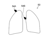
- FIG. 4 shows a state in which marks 54A and 54B made up of arrows indicating each lesion candidate site are displayed on the medical image 50 displayed on the display unit 24 as a mark indicating the lesion candidate site.
- marks 54A and 54B made of arrows are support information.
- the number of lesion candidate sites in the medical image 50 varies depending on the state of the subject. That is, the number of marks as an example of support information added to the medical image 50 is not limited to two, and may be one, may be three or more, and may be zero. is there.
- the support information in the present invention is not particularly limited to the marks (52A, 54A, etc.) shown in FIGS. Any information that can support the interpretation of the interpreter may be used.
- the support information is not limited to a figure, and may be represented by a color, a pattern, or the like. Support information may be represented by text alone, or support information may be represented by a combination of graphics and text.
- auditory information for example, voice data
- tactile information for example, vibration
- Assist information extracted from the medical image by the lesion candidate site extracting unit 31 is not only stored in the storage unit 28 but also registered in the database 16 via the communication unit 21 in this example. That is, by accessing the database 16, the support information is used not only from the image interpretation support device 12 that extracted the support information, but also from other image interpretation support devices 12 or other types of devices connected to the local area network 18. Is possible.
- the line-of-sight detection unit 32 of the present example extracts a portion where the eyes do not move and a portion where the eyes move from a reader image obtained by imaging the image reader with the camera 22, and uses the position of the portion where the eyes do not move as a reference. As described above, the position of the moving part of the eye is detected, and the line-of-sight position on the medical image is calculated based on the detected position of the moving part of the eye.
- the line-of-sight detection unit 32 may detect the locus of movement of the line-of-sight position.
- the line-of-sight detection unit 32 extracts at least one of the eye head portion 62 and the eye corner portion 64 from the image reader image 60 as a reference point, calculates the reference point coordinates, and extracts the iris portion 66 from the image reader image 60 as a moving point. Then, the moving point coordinates are calculated, and the line-of-sight position of the interpreter is calculated from the positional relationship of the moving point coordinates with respect to the reference point coordinates.
- An imaging device that emits infrared rays as the camera 22 to capture an image may be used to detect the line of sight based on the relationship between the reflection position on the cornea of the interpreter's eyes and the position of the pupil.
- the line-of-sight detection unit 32 calculates a reference point coordinate by extracting a cornea reflection image from the image interpreter image 60 as a reference point, and extracts a pupil part (68 in FIG. 5) from the image interpreter image 60 as a moving point. Point coordinates are calculated, and the eye-gaze position of the interpreter is calculated from the positional relationship of the moving point coordinates with respect to the reference point coordinates.
- a device capable of emitting and photographing infrared rays is required, but generally the detection accuracy of the line-of-sight position is likely to be increased.
- the line-of-sight detection in the present invention is not particularly limited when described with reference to FIG. As long as it is a method capable of detecting the gaze of a radiogram interpreter, gaze detection may be performed using another known technique. However, a gaze detection technique that guarantees the accuracy of the gaze position is used to the extent that it can be determined whether or not the gaze is directed to the lesion candidate site in the medical image.
- the gaze determination unit 33 in this example is in a gaze state in which the interpreter gazes at the lesion candidate site when the gaze of the interpreter is directed to the lesion candidate site of the medical image to be interpreted displayed on the display unit 24. It is discriminated whether or not there is a non-gaze state in which the radiogram interpreter is gazing at the lesion candidate site but is not gazing at the lesion candidate site. There are various modes for determining the gaze state.
- the gaze determination unit 33 is a time during which the gaze position stays continuously in the region of the same lesion candidate site. (Residence time) is measured, and when the residence time exceeds a threshold value (specified time), it is determined that the user is in a gaze state. If the line-of-sight position is within the same lesion candidate site area, the dwell time is counted as “staying continuously”. If it moves to, it is determined that it is in a non-gaze state and the dwell time is reset.
- the gaze determination unit 33 extracts a pupil portion from the image interpreter image, detects at least one of a change in the position of the pupil portion, a change in shape, and a change in size, and performs determination based on the change.
- the line-of-sight detection unit 32 in this example performs not only the calculation of the line-of-sight position but also the detection of the state of the pupil of the image interpreter.
- the start detection unit 34 and the end detection unit 35 of this example receive an operation of starting interpretation and ending interpretation from an interpreter using the instruction input unit 23, and detect the start and end of interpretation.
- the input of the start of interpretation and the end of interpretation is received from the interpreter using a manual input (manual input) device such as a keyboard, a mouse, and a touch sensor.
- Interpretation start and interpretation end instructions may be received by a non-manual input device such as voice input or gesture input.
- the instruction input of the interpretation start and the interpretation end from the interpreter may be received by the gaze detection of the gaze detection unit 32.
- the present invention is not particularly limited to the start of interpretation and the end of interpretation, and other instruction inputs may be performed by line-of-sight detection.
- the display control unit 36 of the present example displays the first display state (the medical image to be interpreted) and the support information is not displayed on the display unit 24. Status).
- the display control unit 36 displays the first on the display unit 24. Keep the display state.
- the display control unit 36 performs the first display when the end detection unit 35 detects the end of the interpretation of the interpreter and the gaze determination unit 33 determines that the candidate lesion site has not been observed after the start of the interpretation.
- the display unit 24 is switched from the state to the second display state (at least the support information is displayed).
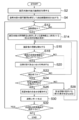
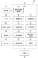
- FIG. 6 is a flowchart showing the flow of processing for an example of an interpretation support method using the interpretation support apparatus of the first embodiment. This process is executed by the CPU 29 according to a program stored in advance in the storage unit 28.
- the medical image to be interpreted is acquired from the database 16 by the communication unit 21 (step S2).
- the lesion candidate site extraction unit 31 analyzes the medical image to be interpreted and extracts a lesion candidate site from the medical image to be interpreted (step S4).
- the lesion candidate site extraction unit 31 creates support information indicating the lesion candidate site.
- the marks 52A and 52B (support information) shown in FIG. 3 or the marks 54A and 54B (support information) shown in FIG. 4 are created based on the analysis result of the medical image.
- “extract a lesion candidate site” recognizes an image of a portion (a lesion candidate site) that may be a lesion site in a medical image by image processing, and at least a lesion in the medical image.
- Information indicating the position of the candidate part is created as support information.
- the marks 52A and 52B formed of closed curves shown in FIG. 3 are created as support information, not only the representative position (for example, the center position) of the lesion candidate site, but also the contour of the lesion candidate site (or the lesion candidate site) Information for specifying a circumscribed figure) or the size of a candidate lesion site is recognized by image processing, and support information is created.
- step S12 it is determined whether or not the image interpreter starts to interpret the medical image to be interpreted.
- the instruction input unit 23 receives an input of a start instruction from an interpreter. That is, it is detected that the interpreter intends to start interpretation.
- the display control unit 36 displays the medical image to be interpreted on the display unit 24 and hides the support information from the display unit 24 (step S12). S14). That is, the display control unit 36 sets the first display state on the display unit 24.
- the gaze detection unit 32 detects the gaze of the radiogram interpreter (step S16).
- step S18 based on the detection result of the eye gaze detection unit 32, it is determined whether or not the eye gaze of the interpreter is directed to the lesion candidate site of the medical image to be interpreted displayed on the display unit 24 (step S18).
- the gaze determination unit 33 determines whether the interpreter is in the gaze state of gazing at the lesion candidate site. It is determined whether or not it is in a non-gaze state in which the line of sight is directed to the lesion candidate site but the lesion candidate site is not watched (step S20).
- step S22 based on the detection result of the end detection unit 35, it is determined whether or not the interpretation of the medical image to be interpreted is complete (step S22).
- the instruction input unit 23 receives an input of an end instruction from a radiogram interpreter. That is, it is detected that the interpreter intends to end the interpretation.
- steps S16 to S22 are repeated.
- step S24 it is determined whether or not a candidate lesion site has been watched after the start of interpretation.
- Step S26 the display control unit 36 maintains the first display state of the display unit 24.
- the display control unit 36 does not display the support information.
- the display unit 24 may be switched to a display state different from the first display state.
- the end detection unit 35 detects the end of interpretation and the gaze determination unit 33 determines that the candidate lesion site has not been observed after the start of interpretation (NO in step S24)
- the support information is displayed on the display unit 24 ( Step S28). That is, the display control unit 36 switches the display unit 24 from the first display state to the second display state.
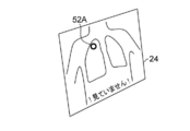
- the marks 52A and 52B shown in FIG. 3 are created as support information, as shown in FIG. 7, the marks 52A and 52B are not displayed in the first display state, but in the second display state. Marks 52A and 52B are displayed. In FIG. 7, a message “! I have not seen!” Is displayed on the display unit 24 together with the marks 52 ⁇ / b> A and 52 ⁇ / b> B.
- the process After setting the second display state, the process returns to step S16, and the interpretation is restarted by the interpreter. In this example, the interpretation is resumed in the second display state.
- the display unit 24 may be returned to the first display state in response to an instruction input by the interpreter or after a predetermined time has elapsed.
- the end detection unit 35 detects the end of interpretation and the gaze determination unit 33 determines that the candidate lesion site has been observed after the start of interpretation (in the case of YES in step S24), the support information on the display unit 24 is not displayed.
- the instruction input unit 23 receives an input of the interpretation result from the interpreter, and creates an interpretation report (step S30).
- the created interpretation report is transmitted to the database 16 by the communication unit 21 and stored in the database 16.
- step S32 it is determined whether or not there is an uninterpreted medical image among the medical images to be interpreted in the database 16 (step S32). If it is determined that there is an uninterpreted medical image (YES in step S32), the process returns to step S12 so that the image interpreter can interpret the next medical image. If it is determined that there is no unread medical image (NO in step S32), the process ends.
- FIG. 7 is used to simplify the case where there is even one unfocused lesion candidate site when the interpreter intends to end the interpretation (NO in step S24 in FIG. 6). Although an example in which all the support information is displayed has been described, the present invention is not limited to such a case.
- the display control unit 36 displays the second display state.
- a mark for example, mark 52B
- the image reader indicates an unwatched lesion candidate site. Only the mark (for example, the mark 52A) is displayed on the display unit 24.
- the image reader can intuitively understand the relationship between the eye movement and the areas that have been watched and the areas that have not been watched. It is preferable to do.
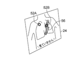
- the display control unit 36 displays the time series of the interpreter. In accordance with the movement of the line of sight, the display mode of the lesion candidate site that has been watched by the interpreter among the plurality of lesion candidate sites is changed. For example, as shown in FIG.
- the display control unit 36 changes the color or pattern of the watched area 56 including the watched lesion candidate part in the medical image to be read into the time-series eye movement of the interpreter. Change to chronological order.
- the display control is performed in such an interaction that the gazed area 56 is gradually erased with an eraser in accordance with the movement of the line of sight.
- display control such as dimming the display of the watched area 56 or setting it to halftone.
- an interpreter can recognize the unfocused lesion candidate site and the watched lesion candidate site separately.
- the display mode of the candidate part is changed.
- “change the display mode of the gazed lesion candidate site” includes the display of the gazed region 56 including the gazed lesion candidate site in the medical image to be interpreted. The case of changing the aspect is included.
- the display control unit 36 may enlarge and display the region of the medical image to be interpreted that is line of sight.
- the display control unit 36 based on the result of the line-of-sight detection by the line-of-sight detection unit 32, corresponds to the region corresponding to the line-of-sight position in the medical image to be interpreted (for example, within a circle with a certain radius centered on the line-of-sight position). Zoom in on (area) only.
- the display control unit 36 stops the enlarged display of a region (for example, a region outside a circle with a constant radius centered on the line-of-sight position) that is distant from the line-of-sight position in the medical image to be interpreted. The enlarged display may be stopped after a certain time has elapsed since the enlarged display was started.
- the display control unit 36 may perform display control in which the visibility of a portion that does not require gaze in the medical image to be interpreted is lower than that of the lesion candidate site.
- the display control unit 36 performs display control such that a portion (part other than the lesion candidate) of the medical image excluding the lesion candidate portion is dimmed or halftone.
- the peripheral part of the lesion candidate site for example, a part within a certain distance from the lesion candidate site
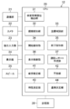
- FIG. 10 is a block diagram illustrating a configuration example of the image interpretation support device 12 according to the second embodiment of the present invention.
- symbol is attached
- the fatigue estimation unit 41 estimates whether it is necessary to recover the interpreter's fatigue by the interpretation of the interpreter.
- the warning unit 42 outputs a warning to the radiogram interpreter when it is estimated by the fatigue estimation unit that recovery of the radiographer's fatigue is necessary.
- the fatigue estimation unit 41 of this example is the number of times the display control unit 36 switches from the first display state (in which support information is not displayed) to the second display state (in which support information is displayed). Based on the above, it is estimated whether recovery from fatigue is necessary. Other aspects of fatigue estimation will be described later.
- the warning output by the warning unit 42 may be performed using the display unit 24 or the speaker 25.
- the warning output from the speaker 25 may be a human voice output or a warning sound output.
- the warning output is not limited to visual output or auditory output, and may be tactile output (for example, generation of vibration).
- FIG. 11 is a flowchart showing the flow of processing for an example of an interpretation support method using the interpretation support apparatus 12 of the second embodiment. This process is executed by the CPU 29 according to a program stored in advance in the storage unit 28.
- the same steps as those in the first embodiment shown in FIG. 6 are denoted by the same reference numerals, and only different items will be described below.
- the display control unit 36 After switching the display state from the first display state (in which support information is not displayed) to the second display state (in which support information is displayed) by control (step S28), The number of times of switching from the first display state to the second display state is compared with the threshold value (step S42).
- “comparison” may be performed by counting the number of switching for each page of the medical image to be interpreted and comparing it with a threshold value.
- the total number of times of switching for each predetermined number of pages may be compared with a threshold value, or the total number of times of switching over an indefinite number of pages may be compared with the threshold value.
- step S42 When the number of times of switching from the first display state to the second display state is equal to or less than the threshold value (in the case of NO in step S42), the process returns to step S16 and the interpretation is resumed.
- step S42 When the number of times of switching from the first display state to the second display state exceeds the threshold value (in the case of YES in step S42), at least one of the display unit 24 and the speaker 25 in this example is controlled by the warning unit 42. Is used to output a warning (step S44).
- this process ends and the interpretation is interrupted. After the warning is output, the interpretation may be resumed at the judgment of the interpreter. That is, the process returns to step S12 in FIG.
- ⁇ Variation of fatigue estimation Referring to FIG. 11, based on the number of times of switching from the first display state to the second display state (that is, the number of times that the interpreter tried to end the interpretation but it was determined that there was an unfocused lesion candidate site). Although an embodiment has been described in which it is determined whether or not a warning output is to be output (that is, whether or not it is necessary to recover an observer's fatigue), the present invention is not limited to such a case. For example, the following variations 1 to 3 may be performed.
- Fatigue estimation is performed based on the cumulative interpretation time of the interpreter. For example, using a built-in timer in the CPU 29 (or a timer provided as a peripheral device of the CPU 29), the fatigue estimation unit 41 calculates the accumulated time from the start of interpretation to the end of interpretation and compares it with a threshold value.
- “cumulative time” preferably uses a cumulative value of interpretation time over a plurality of pages of medical images that have been continuously interpreted by the interpreter. For example, the cumulative value of the interpretation time over the number of indefinite pages that have been continuously interpreted is compared with a threshold value.
- Fatigue estimation is performed based on at least one of the movement speed and movement amount of the sight line of the interpreter.
- the fatigue estimation unit 41 calculates at least one of the movement speed and movement amount of the interpreter's line of sight based on the result of the line-of-sight detection of the line-of-sight detection unit 32 and compares it with a threshold value.
- the “movement speed” and the “movement amount” may be calculated values in a medical image that is currently directed at the line of sight, or may be an average of calculated values over a plurality of pages of medical images that have been continuously read by the interpreter. .
- the average value (moving average) of the movement speed of the line of sight for every certain number of pages that have been read continuously is compared with a threshold value.
- Fatigue estimation is performed based on the blinking speed of the interpreter's eyes.
- a blink detection unit 38 is added, and the blink detection unit 38 detects blinks of the eyes of the interpreter based on the interpreter image captured by the camera 22.
- the fatigue estimation unit 41 calculates the eye blinking speed of the interpreter, compares it with a threshold, and estimates that the interpreter needs to recover from fatigue when the eye blinking speed is less than the threshold. . In this mode, the human characteristic that the blinking speed becomes slower when not tired than when not fatigued is used.
- the time length of one blink is calculated from the time when the line of sight does not hit anywhere in the medical image, and fatigue estimation is performed by comparing with a threshold value.
- the blink detection unit 38 performs blink detection based on the output of the line-of-sight detection unit 32.
- variation of fatigue estimation in the present invention is not particularly limited to the above-described variations 1 to 3. Further, the accuracy of fatigue estimation may be improved by combining various variations.
- FIG. 13 is a block diagram illustrating a configuration example of the image interpretation support device 12 according to the third embodiment of the present invention.
- symbol is attached
- the characteristic measurement unit 43 measures the characteristic of the reader's gaze for each individual.
- the reference determination unit 44 is a reference for determining whether it is a gaze state or a non-gaze state based on the result of measurement for each individual by the characteristic measurement unit 43 (data for each individual of the radiogram interpreter).
- the criteria for estimating whether or not the reader needs to recover from fatigue are determined for each individual.
- the gaze determination unit 33 determines whether the radiogram interpreter is in a gaze state or a non-gaze state based on a determination criterion determined for each individual by the reference determination unit 44. Further, the fatigue estimation unit 41 of the present embodiment estimates whether or not it is necessary to recover the interpreter's fatigue based on the criteria determined for each individual by the criteria determination unit 44.
- the characteristic measuring unit 43 displays, for example, a test pattern for causing the display unit 24 to measure individual characteristics on the first screen on which the execution of a program for supporting interpretation is started, and moves the test pattern on the screen. Measure the follower's line of sight to the movement of the pattern.
- the reference determination unit 44 determines a reference for determining whether the user is in the gaze state or in the non-gaze state based on the followability of the eyesight of the interpreter measured by the characteristic measurement unit 43. Further, the reference determination unit 44 determines a reference for estimating whether or not fatigue recovery is necessary based on the followability of the line of sight of the interpreter measured by the characteristic measurement unit 43.
- the characteristic measurement mode of the characteristic measurement unit 43 is not particularly limited when the above-described test pattern is used.
- the display of the test pattern is not performed, and the characteristic measurement may be performed based on at least one of the line-of-sight movement and the eye state change of the interpreter during interpretation.
- “Determination of the reference for each individual” by the reference determination unit 44 includes a case where a predetermined reference value is automatically adjusted for each radiogram interpreter.
- FIG. 14 is a block diagram illustrating a configuration example of the image interpretation support device 12 according to the fourth embodiment of the present invention. Note that the same components as those in the image interpretation support device 12 of the third embodiment shown in FIG. 13 are denoted by the same reference numerals, and description of the contents already described is omitted below.
- the image interpretation estimation unit 39 estimates whether or not an image interpreter has performed an interpretation from an enlargement operation of a medical image to be interpreted.
- the end detection unit 35 detects that the interpretation is completed only when the interpretation estimation unit 39 estimates that the interpretation has been performed. That is, even when the radiographer intends to end the interpretation, the detection accuracy of the interpretation end can be improved by excluding the case where it is estimated that the interpretation is not actually performed.
- the image interpretation support device 12 may be configured by a plurality of devices, and the processing necessary for image interpretation support may be distributed among these devices. That is, the image interpretation support device 12 shown in FIG. 1 may be configured by a plurality of devices.
- FIG. 15 shows a system configuration example in which the image interpretation support device 12 shown in FIG. 1 is composed of a medical image analysis device 13 and an image interpreter terminal 14.
- the medical image analysis apparatus 13 includes a lesion candidate site extraction unit 31 (31 in FIG. 2, FIG. 10, FIG. 12, FIG. 13 or FIG. 14).
- the radiogram interpreter terminal 14 is a terminal operated by the radiogram interpreter.
- the radiogram interpreter terminal 14 may be an apparatus having a configuration in which the lesion candidate site extraction unit 31 is omitted from the radiogram interpretation support apparatus 12 described in the first to fourth embodiments.
- the communication unit 21 of the radiogram interpreter terminal 14 acquires, via communication, the medical image to be interpreted and the support information indicating the candidate lesion site extracted from the medical image from the database 16 via the local area network 18. .
Landscapes
- Health & Medical Sciences (AREA)
- Life Sciences & Earth Sciences (AREA)
- Engineering & Computer Science (AREA)
- Medical Informatics (AREA)
- Public Health (AREA)
- General Health & Medical Sciences (AREA)
- Biomedical Technology (AREA)
- Physics & Mathematics (AREA)
- Pathology (AREA)
- Animal Behavior & Ethology (AREA)
- Molecular Biology (AREA)
- Surgery (AREA)
- Biophysics (AREA)
- Heart & Thoracic Surgery (AREA)
- Veterinary Medicine (AREA)
- Primary Health Care (AREA)
- Epidemiology (AREA)
- Radiology & Medical Imaging (AREA)
- Nuclear Medicine, Radiotherapy & Molecular Imaging (AREA)
- Physiology (AREA)
- Human Computer Interaction (AREA)
- Ophthalmology & Optometry (AREA)
- Social Psychology (AREA)
- Psychiatry (AREA)
- High Energy & Nuclear Physics (AREA)
- Optics & Photonics (AREA)
- Child & Adolescent Psychology (AREA)
- Hospice & Palliative Care (AREA)
- Educational Technology (AREA)
- Developmental Disabilities (AREA)
- Oral & Maxillofacial Surgery (AREA)
- Dentistry (AREA)
- Psychology (AREA)
- Databases & Information Systems (AREA)
- Data Mining & Analysis (AREA)
- Computer Networks & Wireless Communication (AREA)
- Business, Economics & Management (AREA)
- General Business, Economics & Management (AREA)
- Computer Vision & Pattern Recognition (AREA)
- General Physics & Mathematics (AREA)
Abstract
L'objet de la présente invention est de réaliser un dispositif et un procédé d'aide à l'interprétation de radiographie qui évite que des zones d'une radiographie à interpréter soient ignorées par un radiologue sans interférer avec l'interprétation du radiologue. Elle concerne un dispositif d'aide à l'interprétation de radiographies, comprenant : une unité de détection de ligne de vue (32) qui détecte la ligne de vue d'un radiologue ; une unité d'évaluation de mise au point (33) qui évalue, sur la base du résultat de la détection par l'unité de détection de ligne de vue, si le radiologue a effectué la mise au point sur un site candidat de lésion dans une image de la radiographie à interpréter qui est affichée par une unité d'affichage (24) ; une unité de détection d'interruption (35) qui détecte une interruption de l'interprétation radiologique par le radiologue de l'image de la radiographie à interpréter qui est affichée par l'unité d'affichage ; et une unité de commande d'affichage qui commute d'un premier état d'affichage dans lequel une image de la radiographie à interpréter est affichée par l'unité d'affichage et dans lequel des informations d'aide ne sont pas affichées à un deuxième état d'affichage dans lequel au moins les informations d'aide sont affichées par l'unité d'affichage, si l'interruption de l'interprétation radiologique est détectée par l'unité de détection d'interruption et qu'il est évalué par l'unité d'évaluation de mise au point qu'il n'y a pas eu de mise au point sur le site candidat de lésion.
Priority Applications (3)
| Application Number | Priority Date | Filing Date | Title |
|---|---|---|---|
| EP16838863.5A EP3342343B1 (fr) | 2015-08-24 | 2016-05-26 | Dispositif et procédé d'aide à l'interprétation de radiographies |
| JP2017536638A JP6529144B2 (ja) | 2015-08-24 | 2016-05-26 | 読影支援装置及び方法 |
| US15/891,556 US10456072B2 (en) | 2015-08-24 | 2018-02-08 | Image interpretation support apparatus and method |
Applications Claiming Priority (2)
| Application Number | Priority Date | Filing Date | Title |
|---|---|---|---|
| JP2015-164601 | 2015-08-24 | ||
| JP2015164601 | 2015-08-24 |
Related Child Applications (1)
| Application Number | Title | Priority Date | Filing Date |
|---|---|---|---|
| US15/891,556 Continuation US10456072B2 (en) | 2015-08-24 | 2018-02-08 | Image interpretation support apparatus and method |
Publications (1)
| Publication Number | Publication Date |
|---|---|
| WO2017033516A1 true WO2017033516A1 (fr) | 2017-03-02 |
Family
ID=58099846
Family Applications (1)
| Application Number | Title | Priority Date | Filing Date |
|---|---|---|---|
| PCT/JP2016/065559 WO2017033516A1 (fr) | 2015-08-24 | 2016-05-26 | Dispositif et procédé d'aide à l'interprétation de radiographies |
Country Status (4)
| Country | Link |
|---|---|
| US (1) | US10456072B2 (fr) |
| EP (1) | EP3342343B1 (fr) |
| JP (1) | JP6529144B2 (fr) |
| WO (1) | WO2017033516A1 (fr) |
Cited By (5)
| Publication number | Priority date | Publication date | Assignee | Title |
|---|---|---|---|---|
| WO2019044579A1 (fr) * | 2017-08-31 | 2019-03-07 | 国立大学法人大阪大学 | Appareil de diagnostic de pathologie, procédé de traitement d'images et programme associé |
| EP3493213A1 (fr) * | 2018-02-13 | 2019-06-05 | Siemens Healthcare GmbH | Procédé, système, produit-programme d'ordinateur et support lisible par ordinateur pour prendre en charge une analyse visuelle d'un ensemble de données d'images médicales |
| WO2019198808A1 (fr) * | 2018-04-13 | 2019-10-17 | 学校法人昭和大学 | Dispositif d'aide au diagnostic endoscopique, procédé d'aide au diagnostic endoscopique et programme |
| WO2022064794A1 (fr) * | 2020-09-28 | 2022-03-31 | 富士フイルム株式会社 | Dispositif, procédé et programme d'affichage d'image |
| WO2022220081A1 (fr) * | 2021-04-14 | 2022-10-20 | 富士フイルム株式会社 | Dispositif d'aide à la création de documents, procédé d'aide à la création de documents et programme d'aide à la création de documents |
Families Citing this family (7)
| Publication number | Priority date | Publication date | Assignee | Title |
|---|---|---|---|---|
| KR101840350B1 (ko) * | 2015-09-24 | 2018-03-20 | 주식회사 뷰노 | 의료 영상 판독 과정에서 사용자의 시선 정보를 이용한 판독 효율 증대 방법 및 그 장치 |
| CN112368668B (zh) * | 2018-07-03 | 2024-03-22 | 瑞典爱立信有限公司 | 用于混合现实头戴式耳机的便携式电子设备 |
| JP7121583B2 (ja) * | 2018-08-07 | 2022-08-18 | 本田技研工業株式会社 | 表示装置、表示制御方法、およびプログラム |
| WO2020110214A1 (fr) * | 2018-11-28 | 2020-06-04 | オリンパス株式会社 | Système d'endoscope, procédé de traitement d'image pour endoscope, et programme de traitement d'image pour endoscope |
| JP2021148506A (ja) | 2020-03-17 | 2021-09-27 | 本田技研工業株式会社 | 表示制御装置、表示制御方法およびプログラム |
| JPWO2022113587A1 (fr) * | 2020-11-27 | 2022-06-02 | ||
| US20220265183A1 (en) * | 2021-02-19 | 2022-08-25 | Canon Medical Systems Corporation | Method and apparatus for displaying medical images |
Citations (10)
| Publication number | Priority date | Publication date | Assignee | Title |
|---|---|---|---|---|
| JPH0370381A (ja) * | 1989-08-10 | 1991-03-26 | Fuji Photo Film Co Ltd | 画像表示装置 |
| JP2000342537A (ja) * | 1999-06-03 | 2000-12-12 | Nec Corp | 眼疲労警告装置および眼疲労警告方法 |
| JP2005348936A (ja) * | 2004-06-10 | 2005-12-22 | Konica Minolta Medical & Graphic Inc | 医用画像表示システム、プログラム及び医用画像表示方法 |
| JP2007319327A (ja) * | 2006-05-31 | 2007-12-13 | Hitachi Medical Corp | 読影支援システム |
| JP2008099929A (ja) * | 2006-10-20 | 2008-05-01 | Fujifilm Corp | 異常陰影候補表示装置 |
| JP2009125154A (ja) * | 2007-11-20 | 2009-06-11 | Hamamatsu Photonics Kk | 瞬目計測装置 |
| JP2010035756A (ja) * | 2008-08-04 | 2010-02-18 | Fujifilm Corp | 診断支援装置及び診断支援方法 |
| JP2011175620A (ja) * | 2010-02-23 | 2011-09-08 | Fuji Xerox Co Ltd | 画像分析支援方法、画像分析支援システムおよび画像分析支援のためのプログラム |
| JP2012196279A (ja) * | 2011-03-18 | 2012-10-18 | Waseda Univ | 注目度検出システム、注目度判定装置、注目度判定装置用のプログラム、及び画像配信システム |
| JP2014123179A (ja) * | 2012-12-20 | 2014-07-03 | Fujitsu Ltd | 情報処理装置、情報処理方法、見落し防止プログラム |
Family Cites Families (6)
| Publication number | Priority date | Publication date | Assignee | Title |
|---|---|---|---|---|
| US8020993B1 (en) * | 2006-01-30 | 2011-09-20 | Fram Evan K | Viewing verification systems |
| JP5159041B2 (ja) | 2006-01-30 | 2013-03-06 | 株式会社東芝 | 超音波診断装置およびその画像処理プログラム |
| WO2010051037A1 (fr) * | 2008-11-03 | 2010-05-06 | Bruce Reiner | Interaction homme-ordinateur à commande visuelle pour des applications médicales |
| WO2014039337A1 (fr) * | 2012-09-07 | 2014-03-13 | Tractus Corporation | Procédés, appareil et systèmes de visualisation d'images médicales à coupes multiples |
| JP6165033B2 (ja) | 2013-11-14 | 2017-07-19 | オリンパス株式会社 | 医療システム |
| JP5997791B2 (ja) | 2015-02-10 | 2016-09-28 | キヤノン株式会社 | 診断支援装置、診断支援装置の制御方法、プログラム及び記憶媒体 |
-
2016
- 2016-05-26 JP JP2017536638A patent/JP6529144B2/ja active Active
- 2016-05-26 WO PCT/JP2016/065559 patent/WO2017033516A1/fr unknown
- 2016-05-26 EP EP16838863.5A patent/EP3342343B1/fr active Active
-
2018
- 2018-02-08 US US15/891,556 patent/US10456072B2/en active Active
Patent Citations (10)
| Publication number | Priority date | Publication date | Assignee | Title |
|---|---|---|---|---|
| JPH0370381A (ja) * | 1989-08-10 | 1991-03-26 | Fuji Photo Film Co Ltd | 画像表示装置 |
| JP2000342537A (ja) * | 1999-06-03 | 2000-12-12 | Nec Corp | 眼疲労警告装置および眼疲労警告方法 |
| JP2005348936A (ja) * | 2004-06-10 | 2005-12-22 | Konica Minolta Medical & Graphic Inc | 医用画像表示システム、プログラム及び医用画像表示方法 |
| JP2007319327A (ja) * | 2006-05-31 | 2007-12-13 | Hitachi Medical Corp | 読影支援システム |
| JP2008099929A (ja) * | 2006-10-20 | 2008-05-01 | Fujifilm Corp | 異常陰影候補表示装置 |
| JP2009125154A (ja) * | 2007-11-20 | 2009-06-11 | Hamamatsu Photonics Kk | 瞬目計測装置 |
| JP2010035756A (ja) * | 2008-08-04 | 2010-02-18 | Fujifilm Corp | 診断支援装置及び診断支援方法 |
| JP2011175620A (ja) * | 2010-02-23 | 2011-09-08 | Fuji Xerox Co Ltd | 画像分析支援方法、画像分析支援システムおよび画像分析支援のためのプログラム |
| JP2012196279A (ja) * | 2011-03-18 | 2012-10-18 | Waseda Univ | 注目度検出システム、注目度判定装置、注目度判定装置用のプログラム、及び画像配信システム |
| JP2014123179A (ja) * | 2012-12-20 | 2014-07-03 | Fujitsu Ltd | 情報処理装置、情報処理方法、見落し防止プログラム |
Cited By (8)
| Publication number | Priority date | Publication date | Assignee | Title |
|---|---|---|---|---|
| WO2019044579A1 (fr) * | 2017-08-31 | 2019-03-07 | 国立大学法人大阪大学 | Appareil de diagnostic de pathologie, procédé de traitement d'images et programme associé |
| JPWO2019044579A1 (ja) * | 2017-08-31 | 2020-11-05 | 国立大学法人大阪大学 | 病理診断装置、画像処理方法及びプログラム |
| EP3493213A1 (fr) * | 2018-02-13 | 2019-06-05 | Siemens Healthcare GmbH | Procédé, système, produit-programme d'ordinateur et support lisible par ordinateur pour prendre en charge une analyse visuelle d'un ensemble de données d'images médicales |
| WO2019198808A1 (fr) * | 2018-04-13 | 2019-10-17 | 学校法人昭和大学 | Dispositif d'aide au diagnostic endoscopique, procédé d'aide au diagnostic endoscopique et programme |
| JP2019180966A (ja) * | 2018-04-13 | 2019-10-24 | 学校法人昭和大学 | 内視鏡観察支援装置、内視鏡観察支援方法、及びプログラム |
| CN111970955A (zh) * | 2018-04-13 | 2020-11-20 | 学校法人昭和大学 | 内窥镜观察辅助装置、内窥镜观察辅助方法及程序 |
| WO2022064794A1 (fr) * | 2020-09-28 | 2022-03-31 | 富士フイルム株式会社 | Dispositif, procédé et programme d'affichage d'image |
| WO2022220081A1 (fr) * | 2021-04-14 | 2022-10-20 | 富士フイルム株式会社 | Dispositif d'aide à la création de documents, procédé d'aide à la création de documents et programme d'aide à la création de documents |
Also Published As
| Publication number | Publication date |
|---|---|
| JP6529144B2 (ja) | 2019-06-12 |
| US10456072B2 (en) | 2019-10-29 |
| EP3342343A4 (fr) | 2018-09-26 |
| US20180177446A1 (en) | 2018-06-28 |
| EP3342343A1 (fr) | 2018-07-04 |
| EP3342343B1 (fr) | 2019-11-27 |
| JPWO2017033516A1 (ja) | 2018-06-07 |
Similar Documents
| Publication | Publication Date | Title |
|---|---|---|
| WO2017033516A1 (fr) | Dispositif et procédé d'aide à l'interprétation de radiographies | |
| US20180157323A1 (en) | Eye gaze determination | |
| KR101331655B1 (ko) | 전자 데이터 입력 방법, 시스템 및 컴퓨터 판독 가능한 매체 | |
| US7396129B2 (en) | Diagnostic system having gaze tracking | |
| CN106659441B (zh) | 评价医生注意力 | |
| EP3570771B1 (fr) | Réalité augmentée pour surveillance des doses de rayonnement | |
| EP2818115B1 (fr) | Appareil de diagnostic par ultrasons et son procédé de fonctionnement | |
| CN105473059B (zh) | 在成像数据集之间对发现的匹配 | |
| US20200162664A1 (en) | Input control device, input control method, and operation system | |
| KR102326489B1 (ko) | 디스플레이를 제어하는 전자 장치 및 방법 | |
| JP6755192B2 (ja) | 診断支援装置および診断支援装置の作動方法 | |
| KR102508831B1 (ko) | 원격 이미지 전송 시스템, 디스플레이 장치 및 그의 가이드 표시 방법 | |
| Eckstein et al. | Evaluation of search strategies for microcalcifications and masses in 3D images | |
| JP6501525B2 (ja) | 情報処理装置、情報処理方法およびプログラム | |
| US11409422B2 (en) | Device, system and method for interacting with vessel images | |
| US20220327704A1 (en) | Method for determining location of target of body | |
| CN114740966A (zh) | 多模态图像显示控制方法、系统及计算机设备 | |
| EP4286991A1 (fr) | Guidage pour interventions médicales | |
| KR101643744B1 (ko) | 시선고정 눈 반응 감지장치 및 방법 | |
| CN113095243B (zh) | 一种鼠标控制的方法、装置、计算机设备和介质 | |
| Klein et al. | The perceptual influence of 2D synthesized images on 3D search | |
| WO2023232612A1 (fr) | Guidage pour interventions médicales | |
| JP2024024307A (ja) | 画像処理装置、画像処理方法およびプログラム | |
| Brandon et al. | Virtual Visit: A Web-based Assistive Interface for Touring Cultural Spaces Remotely | |
| Kaminaga et al. | Study on Operation of Environmental control systems using Head Movement and Eye gazing |
Legal Events
| Date | Code | Title | Description |
|---|---|---|---|
| 121 | Ep: the epo has been informed by wipo that ep was designated in this application |
Ref document number: 16838863 Country of ref document: EP Kind code of ref document: A1 |
|
| ENP | Entry into the national phase |
Ref document number: 2017536638 Country of ref document: JP Kind code of ref document: A |
|
| NENP | Non-entry into the national phase |
Ref country code: DE |