WO2017033516A1 - Radiograph interpretation assistance device and method - Google Patents
Radiograph interpretation assistance device and method Download PDFInfo
- Publication number
- WO2017033516A1 WO2017033516A1 PCT/JP2016/065559 JP2016065559W WO2017033516A1 WO 2017033516 A1 WO2017033516 A1 WO 2017033516A1 JP 2016065559 W JP2016065559 W JP 2016065559W WO 2017033516 A1 WO2017033516 A1 WO 2017033516A1
- Authority
- WO
- WIPO (PCT)
- Prior art keywords
- image
- interpretation
- unit
- gaze
- interpreter
- Prior art date
Links
Images


Classifications
-
- A—HUMAN NECESSITIES
- A61—MEDICAL OR VETERINARY SCIENCE; HYGIENE
- A61B—DIAGNOSIS; SURGERY; IDENTIFICATION
- A61B5/00—Measuring for diagnostic purposes; Identification of persons
- A61B5/16—Devices for psychotechnics; Testing reaction times ; Devices for evaluating the psychological state
- A61B5/163—Devices for psychotechnics; Testing reaction times ; Devices for evaluating the psychological state by tracking eye movement, gaze, or pupil change
-
- A—HUMAN NECESSITIES
- A61—MEDICAL OR VETERINARY SCIENCE; HYGIENE
- A61B—DIAGNOSIS; SURGERY; IDENTIFICATION
- A61B3/00—Apparatus for testing the eyes; Instruments for examining the eyes
- A61B3/10—Objective types, i.e. instruments for examining the eyes independent of the patients' perceptions or reactions
- A61B3/113—Objective types, i.e. instruments for examining the eyes independent of the patients' perceptions or reactions for determining or recording eye movement
-
- A—HUMAN NECESSITIES
- A61—MEDICAL OR VETERINARY SCIENCE; HYGIENE
- A61B—DIAGNOSIS; SURGERY; IDENTIFICATION
- A61B5/00—Measuring for diagnostic purposes; Identification of persons
- A61B5/0002—Remote monitoring of patients using telemetry, e.g. transmission of vital signals via a communication network
- A61B5/0015—Remote monitoring of patients using telemetry, e.g. transmission of vital signals via a communication network characterised by features of the telemetry system
- A61B5/002—Monitoring the patient using a local or closed circuit, e.g. in a room or building
-
- A—HUMAN NECESSITIES
- A61—MEDICAL OR VETERINARY SCIENCE; HYGIENE
- A61B—DIAGNOSIS; SURGERY; IDENTIFICATION
- A61B5/00—Measuring for diagnostic purposes; Identification of persons
- A61B5/0059—Measuring for diagnostic purposes; Identification of persons using light, e.g. diagnosis by transillumination, diascopy, fluorescence
- A61B5/0077—Devices for viewing the surface of the body, e.g. camera, magnifying lens
-
- A—HUMAN NECESSITIES
- A61—MEDICAL OR VETERINARY SCIENCE; HYGIENE
- A61B—DIAGNOSIS; SURGERY; IDENTIFICATION
- A61B5/00—Measuring for diagnostic purposes; Identification of persons
- A61B5/103—Detecting, measuring or recording devices for testing the shape, pattern, colour, size or movement of the body or parts thereof, for diagnostic purposes
- A61B5/11—Measuring movement of the entire body or parts thereof, e.g. head or hand tremor, mobility of a limb
- A61B5/1103—Detecting eye twinkling
-
- A—HUMAN NECESSITIES
- A61—MEDICAL OR VETERINARY SCIENCE; HYGIENE
- A61B—DIAGNOSIS; SURGERY; IDENTIFICATION
- A61B5/00—Measuring for diagnostic purposes; Identification of persons
- A61B5/74—Details of notification to user or communication with user or patient ; user input means
- A61B5/7405—Details of notification to user or communication with user or patient ; user input means using sound
-
- A—HUMAN NECESSITIES
- A61—MEDICAL OR VETERINARY SCIENCE; HYGIENE
- A61B—DIAGNOSIS; SURGERY; IDENTIFICATION
- A61B5/00—Measuring for diagnostic purposes; Identification of persons
- A61B5/74—Details of notification to user or communication with user or patient ; user input means
- A61B5/742—Details of notification to user or communication with user or patient ; user input means using visual displays
- A61B5/743—Displaying an image simultaneously with additional graphical information, e.g. symbols, charts, function plots
-
- A—HUMAN NECESSITIES
- A61—MEDICAL OR VETERINARY SCIENCE; HYGIENE
- A61B—DIAGNOSIS; SURGERY; IDENTIFICATION
- A61B5/00—Measuring for diagnostic purposes; Identification of persons
- A61B5/74—Details of notification to user or communication with user or patient ; user input means
- A61B5/746—Alarms related to a physiological condition, e.g. details of setting alarm thresholds or avoiding false alarms
-
- A—HUMAN NECESSITIES
- A61—MEDICAL OR VETERINARY SCIENCE; HYGIENE
- A61B—DIAGNOSIS; SURGERY; IDENTIFICATION
- A61B6/00—Apparatus for radiation diagnosis, e.g. combined with radiation therapy equipment
- A61B6/46—Apparatus for radiation diagnosis, e.g. combined with radiation therapy equipment with special arrangements for interfacing with the operator or the patient
- A61B6/461—Displaying means of special interest
-
- G—PHYSICS
- G06—COMPUTING; CALCULATING OR COUNTING
- G06V—IMAGE OR VIDEO RECOGNITION OR UNDERSTANDING
- G06V40/00—Recognition of biometric, human-related or animal-related patterns in image or video data
- G06V40/20—Movements or behaviour, e.g. gesture recognition
-
- G—PHYSICS
- G16—INFORMATION AND COMMUNICATION TECHNOLOGY [ICT] SPECIALLY ADAPTED FOR SPECIFIC APPLICATION FIELDS
- G16H—HEALTHCARE INFORMATICS, i.e. INFORMATION AND COMMUNICATION TECHNOLOGY [ICT] SPECIALLY ADAPTED FOR THE HANDLING OR PROCESSING OF MEDICAL OR HEALTHCARE DATA
- G16H15/00—ICT specially adapted for medical reports, e.g. generation or transmission thereof
-
- G—PHYSICS
- G16—INFORMATION AND COMMUNICATION TECHNOLOGY [ICT] SPECIALLY ADAPTED FOR SPECIFIC APPLICATION FIELDS
- G16H—HEALTHCARE INFORMATICS, i.e. INFORMATION AND COMMUNICATION TECHNOLOGY [ICT] SPECIALLY ADAPTED FOR THE HANDLING OR PROCESSING OF MEDICAL OR HEALTHCARE DATA
- G16H30/00—ICT specially adapted for the handling or processing of medical images
- G16H30/20—ICT specially adapted for the handling or processing of medical images for handling medical images, e.g. DICOM, HL7 or PACS
-
- G—PHYSICS
- G16—INFORMATION AND COMMUNICATION TECHNOLOGY [ICT] SPECIALLY ADAPTED FOR SPECIFIC APPLICATION FIELDS
- G16H—HEALTHCARE INFORMATICS, i.e. INFORMATION AND COMMUNICATION TECHNOLOGY [ICT] SPECIALLY ADAPTED FOR THE HANDLING OR PROCESSING OF MEDICAL OR HEALTHCARE DATA
- G16H40/00—ICT specially adapted for the management or administration of healthcare resources or facilities; ICT specially adapted for the management or operation of medical equipment or devices
- G16H40/60—ICT specially adapted for the management or administration of healthcare resources or facilities; ICT specially adapted for the management or operation of medical equipment or devices for the operation of medical equipment or devices
-
- G—PHYSICS
- G16—INFORMATION AND COMMUNICATION TECHNOLOGY [ICT] SPECIALLY ADAPTED FOR SPECIFIC APPLICATION FIELDS
- G16H—HEALTHCARE INFORMATICS, i.e. INFORMATION AND COMMUNICATION TECHNOLOGY [ICT] SPECIALLY ADAPTED FOR THE HANDLING OR PROCESSING OF MEDICAL OR HEALTHCARE DATA
- G16H50/00—ICT specially adapted for medical diagnosis, medical simulation or medical data mining; ICT specially adapted for detecting, monitoring or modelling epidemics or pandemics
- G16H50/20—ICT specially adapted for medical diagnosis, medical simulation or medical data mining; ICT specially adapted for detecting, monitoring or modelling epidemics or pandemics for computer-aided diagnosis, e.g. based on medical expert systems
-
- A—HUMAN NECESSITIES
- A61—MEDICAL OR VETERINARY SCIENCE; HYGIENE
- A61B—DIAGNOSIS; SURGERY; IDENTIFICATION
- A61B5/00—Measuring for diagnostic purposes; Identification of persons
- A61B5/05—Detecting, measuring or recording for diagnosis by means of electric currents or magnetic fields; Measuring using microwaves or radio waves
- A61B5/055—Detecting, measuring or recording for diagnosis by means of electric currents or magnetic fields; Measuring using microwaves or radio waves involving electronic [EMR] or nuclear [NMR] magnetic resonance, e.g. magnetic resonance imaging
-
- A—HUMAN NECESSITIES
- A61—MEDICAL OR VETERINARY SCIENCE; HYGIENE
- A61B—DIAGNOSIS; SURGERY; IDENTIFICATION
- A61B5/00—Measuring for diagnostic purposes; Identification of persons
- A61B5/16—Devices for psychotechnics; Testing reaction times ; Devices for evaluating the psychological state
- A61B5/18—Devices for psychotechnics; Testing reaction times ; Devices for evaluating the psychological state for vehicle drivers or machine operators
-
- A—HUMAN NECESSITIES
- A61—MEDICAL OR VETERINARY SCIENCE; HYGIENE
- A61B—DIAGNOSIS; SURGERY; IDENTIFICATION
- A61B6/00—Apparatus for radiation diagnosis, e.g. combined with radiation therapy equipment
- A61B6/52—Devices using data or image processing specially adapted for radiation diagnosis
- A61B6/5211—Devices using data or image processing specially adapted for radiation diagnosis involving processing of medical diagnostic data
- A61B6/5217—Devices using data or image processing specially adapted for radiation diagnosis involving processing of medical diagnostic data extracting a diagnostic or physiological parameter from medical diagnostic data
-
- G—PHYSICS
- G06—COMPUTING; CALCULATING OR COUNTING
- G06V—IMAGE OR VIDEO RECOGNITION OR UNDERSTANDING
- G06V40/00—Recognition of biometric, human-related or animal-related patterns in image or video data
- G06V40/10—Human or animal bodies, e.g. vehicle occupants or pedestrians; Body parts, e.g. hands
- G06V40/18—Eye characteristics, e.g. of the iris
- G06V40/19—Sensors therefor
Definitions
- the present invention relates to an interpretation support apparatus and method, and more particularly, to an interpretation support technique that can prevent oversight of an interpreter without interfering with the interpretation of the interpreter.
- An interpreting doctor may interpret a large amount of medical images (for example, X-ray images) per day.
- medical images for example, X-ray images
- regular doctors and doctors specializing in remote interpretation need to interpret in a short time, which increases the risk of overlooking the lesion site.
- a lesion candidate site such as a shadow existing in a medical image to be interpreted is automatically recognized by image processing, and a mark (support information) indicating the lesion site is used as a medical image.
- a technique is known in which an image interpretation doctor is notified during interpretation of which part of a medical image to be interpreted is to be watched by displaying it above (Patent Document 1).
- Patent Documents 2 and 3 there has been proposed a medical device capable of inputting instructions without touching anything by voice, line of sight, or gesture in a medical field where both hands are occupied.
- Patent Document 2 is a configuration in which image operations such as enlargement / reduction are performed by a combination of voice input and line-of-sight input, and voice input is necessary, so that the voice of another person, BGM (Back Ground Music), etc. Certain operations cannot be performed in an environment with a high level of noise. Moreover, even if the instruction can be input without touching anything, it still takes time to input the instruction.
- Patent Document 3 The technique described in Patent Document 3 is configured to execute a command corresponding to an icon by moving the line-of-sight position to the displayed icon and gazing for a predetermined time, and it is necessary to move the line-of-sight position to the icon. Therefore, it is not possible to expect an effect that does not interfere with the interpretation of the reader. Moreover, the effect which prevents an overlooker's oversight cannot be expected.
- the present invention has been made in view of such circumstances, and an object thereof is to provide an interpretation support apparatus and method capable of preventing an overlooker from overlooking without disturbing the interpretation of the interpreter.
- an interpretation support apparatus includes a lesion candidate part extraction unit that analyzes an image to be interpreted and extracts a candidate lesion part from the image to be interpreted, and an image to be interpreted. And an image of the interpretation target displayed on the display unit based on the detection result of the gaze detection unit, the gaze detection unit that detects the gaze of the image interpreter , A gaze determination unit that determines whether or not a candidate lesion site has been watched by an interpreter, an end detection unit that detects the end of the interpretation of the image reader on the image to be interpreted displayed on the display unit, and an end detection A first display in which an image to be interpreted is displayed on the display unit and support information is not displayed when the end of the interpretation is detected by the unit and the gaze determination unit determines that the candidate lesion site has not been watched From state to display A display control unit to switch to a second display state displaying support information even without a interpretation support apparatus comprising a.
- the display control unit may maintain the first display state when the end detection unit detects the end of the interpretation and the gaze determination unit determines that the lesion candidate site has been watched.
- the display control unit displays the support information that is not displayed and is different from the first display state.
- the display unit may be switched.
- the “detection of the end of interpretation” in this aspect is not particularly limited to detecting an instruction input (for example, manual operation, voice input, gesture, etc.) indicating the end of interpretation from the interpreter, and the end of interpretation from the interpreter. Even if there is no explicit instruction input indicating that the radiogram reader detects or estimates that the radiographer intends to end the radiogram interpretation (for example, the image of the radiographer obtained by imaging the radiographer is analyzed by image processing) Detection or estimation).
- an instruction input for example, manual operation, voice input, gesture, etc.
- the end detection unit detects the end of the interpretation and the gaze determination unit determines that the candidate lesion site has been watched
- the support information is not displayed, but the end detection unit
- the end detection unit When the end of the interpretation is detected and the gaze discrimination unit determines that the candidate lesion site has not been gaze, support information indicating the lesion candidate site is displayed to the interpreter, so the interpreter supports during interpretation It is possible to increase concentration on gaze of the lesion site without being obstructed by the information, and when there is a non-gaze lesion candidate site at the end of the interpretation, the interpretation is resumed by knowing that fact. That is, according to this aspect, it is possible to prevent an overlooker's oversight without disturbing the interpreter's interpretation.
- the display control unit when there are a plurality of lesion candidate sites in the image to be interpreted, is read by the interpreter among the plurality of lesion candidate sites in the second display state.
- the support information of the non-gazeable lesion candidate site is displayed by the radiogram interpreter while the support information of the gazeable lesion candidate site is not displayed.
- the display control unit when there are a plurality of lesion candidate sites in the image to be interpreted, includes the candidate lesion sites that have been watched by the interpreter among the plurality of lesion candidate sites. By changing the display mode, it is displayed separately from the candidate lesion site that has not been gazed by the radiogram interpreter.
- the radiogram interpreter concentrates on only the non-gazing lesion candidate sites in which the display mode is maintained, except for the gaze candidate lesion sites in which the display mode is changed according to his / her own line of sight movement. It becomes possible to watch. In other words, interpretation control is improved by performing display control that interactively reacts to the eye movement of the interpreter.
- the fatigue estimation unit that estimates whether or not the fatigue recovery by the interpretation of the image interpreter is necessary, and the fatigue estimation unit needs to recover the fatigue.
- a warning unit for outputting a warning in the case of a warning According to this aspect, when the radiographer is tired, resting of the radiographer is prompted. In other words, it is possible for the image reader to keep his concentration.
- the fatigue estimation unit determines whether it is necessary to recover from fatigue based on the number of times the display control unit switches from the first display state to the second display state. Estimate.
- the fatigue estimation unit estimates whether or not fatigue recovery is necessary based on the accumulation of interpretation time.
- the fatigue estimation unit needs to recover from fatigue based on at least one of the line-of-sight movement speed and the amount of movement detected by the line-of-sight detection unit. Estimate.
- the image interpretation support device includes a blink detection unit that detects blinks of the interpreter, and is the fatigue estimation unit required to recover from fatigue based on the blink rate of the eyes? Estimate whether or not. According to this aspect, it is possible to reduce the possibility of erroneous determination that the user is fatigued due to personal characteristics even though he is not fatigued. That is, it is possible to reduce the output of a warning due to erroneous determination.
- the fatigue estimation unit estimates whether or not it is necessary to recover from fatigue based on data for each individual of the interpreter.
- the display control unit enlarges and displays an area to which the line of sight of the image to be interpreted is directed, and starts the enlarged display when the line of sight is off. After a certain amount of time has elapsed, the enlarged display is stopped.
- the display control unit lowers the visibility of a portion that does not require gaze than the lesion candidate site in the image to be interpreted.
- an instruction input from the image interpreter is received by the line-of-sight detection of the line-of-sight detection unit.
- the gaze determination unit determines whether the image interpreter is a lesion candidate when the image reader's line of sight is directed to the lesion candidate site of the image to be interpreted displayed on the display unit. It is determined whether the state is a gaze state in which the region is gazeed or whether the image reader is in a non-gaze state in which the gaze is directed to the lesion candidate region but not in the lesion candidate region.
- the gaze determination unit determines whether the gaze state is in the gaze state or the non-gaze state based on the dwell time of the interpreter's line of sight to the candidate lesion site. .
- the gaze determination unit determines whether it is a gaze state or a non-gaze state based on the state of the pupil of the interpreter.
- a gaze state is based on a result of measurement for each individual by the characteristic measurement unit and a characteristic measurement unit that measures the characteristic of the gaze of the interpreter for each individual
- a standard determination unit that determines, for each individual, a criterion for determining whether or not the subject is in a non-gaze state, and the gaze determination unit determines whether the reader is based on the criterion for determination determined for each individual by the standard determination unit. It is determined whether it is a gaze state or a non-gaze state.
- the characteristic measurement unit displays a test pattern on the display unit and moves the test pattern on the screen, measures the followability of the gaze of the interpreter with respect to the movement of the test pattern, and gazes
- the discriminating unit determines a criterion for discriminating whether it is a gaze state or a non-gaze state based on the followability of the line of sight of the interpreter measured by the characteristic measurement unit.
- An image interpretation support apparatus includes an image interpretation estimation unit that estimates whether or not an image interpreter has performed an interpretation from an enlargement operation of an image to be interpreted, and the end detection unit is interpreted by the image interpretation estimation unit. Only when it is estimated that the interpretation has been performed, it is detected that the interpretation has ended.
- An interpretation support method includes a step of analyzing an image to be interpreted and extracting a candidate lesion site from the image to be interpreted, displaying an image to be interpreted on a display unit, and selecting a candidate lesion site.
- the second display state in which at least the support information is displayed on the display unit from the first display state in which the image to be interpreted is displayed on the display unit and the support information is not displayed.
- an overlooker can be prevented from being overlooked without disturbing the interpreter.
- FIG. 1 is a system configuration diagram showing an example of a medical system provided with an image interpretation support apparatus according to the present invention.
- the medical system shown in FIG. 1 includes a modality 10, an image interpretation support device 12, and a database 16 that are connected to each other via a local area network 18 so that they can communicate with each other.
- FIG. 1 shows a configuration in which each device is connected to the local area network 18 for convenience of explanation, but a plurality of types of modalities are connected to the local area network 18.
- a plurality of interpretation support devices 12 are also connected according to the number of interpreters.
- a plurality of databases 16 may be connected and distributed.
- the modality 10 is a medical image photographing apparatus that generates and outputs medical image data by photographing a subject (human, animal, etc.).
- the modality 10 of this example adds additional information defined by DICOM (digital imaging and communication in medicine) standards to medical image data.
- Specific examples of the modality 10 include an X-ray simple imaging apparatus, a CT (computed tomography) imaging apparatus, an MRI (magnetic resonance imaging) imaging apparatus, a PET (positron emission tomography) imaging apparatus, and an ultrasonic imaging apparatus. It is done.
- the image interpretation support device 12 is a device that supports the interpretation of medical images by an image interpreter. For example, it is configured by a computer device. Specific examples will be described later.
- the database 16 stores medical image data and data for supporting interpretation of medical images (such as support information data described later).
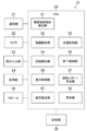
- FIG. 2 is a block diagram illustrating a configuration example of the image interpretation support device 12 according to the first embodiment of the present invention.
- the image interpretation support device 12 of the present embodiment includes a communication unit 21 that can communicate with each device (for example, the database 16) connected to the local area network 18 and an image of the image reader (hereinafter referred to as “interpreter”).
- a camera 22 that outputs an image
- an instruction input unit 23 that receives an instruction input from an interpreter
- a display unit 24 that displays an image to the interpreter
- a program for supporting interpretation and execution of the program
- a storage unit 28 that stores necessary information
- a CPU (central processing unit) 29 that controls each unit of the image interpretation support device 12 according to a program stored in the storage unit 28 are provided.
- the CPU 29 of this embodiment analyzes a medical image to be interpreted acquired from the database 16 by the communication unit 21 and extracts a lesion candidate site extracting unit 31 that extracts a lesion candidate site from the medical image to be interpreted, and a camera 22.
- a gaze position By detecting the gaze of the radiographer based on the image of the radiographer imaged by, the position of the radiographer in the medical image to be interpreted displayed on the display unit 24 (hereinafter referred to as “gaze position”). And whether or not a candidate lesion site in the medical image to be interpreted displayed on the display unit 24 has been watched by the interpreter based on the detection result of the gaze detection unit 32 and the gaze detection unit 32.
- the end detection unit 35 for detecting the end of the interpretation of the radiographer for the medical image, the extraction result of the lesion candidate site extraction unit 31, the detection result of the gaze detection unit 32, the determination result of the gaze determination unit 33, and the start detection unit 34 Based on the detection result and the detection result of the end detection unit 35, an interpretation report is created based on the display control unit 36 that controls the display of the display unit 24 and the interpretation result of the interpreter input to the instruction input unit 23.
- An interpretation report creating unit 37 is provided.
- the display unit 24 can display a medical image to be interpreted and a support image indicating a lesion candidate site as necessary according to display control of the display control unit 36.
- FIG. 3 shows a state in which marks 52A and 52B made up of closed curves surrounding all or a part of each lesion candidate site are superimposed and displayed on the medical image 50 displayed on the display unit 24 as a mark indicating the lesion candidate site.
- marks 52A and 52B made of closed curves are support information.
- the closed curve for example, a frame of a figure (for example, a circle or a polygon) circumscribing a lesion candidate site is used.
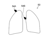
- FIG. 4 shows a state in which marks 54A and 54B made up of arrows indicating each lesion candidate site are displayed on the medical image 50 displayed on the display unit 24 as a mark indicating the lesion candidate site.
- marks 54A and 54B made of arrows are support information.
- the number of lesion candidate sites in the medical image 50 varies depending on the state of the subject. That is, the number of marks as an example of support information added to the medical image 50 is not limited to two, and may be one, may be three or more, and may be zero. is there.
- the support information in the present invention is not particularly limited to the marks (52A, 54A, etc.) shown in FIGS. Any information that can support the interpretation of the interpreter may be used.
- the support information is not limited to a figure, and may be represented by a color, a pattern, or the like. Support information may be represented by text alone, or support information may be represented by a combination of graphics and text.
- auditory information for example, voice data
- tactile information for example, vibration
- Assist information extracted from the medical image by the lesion candidate site extracting unit 31 is not only stored in the storage unit 28 but also registered in the database 16 via the communication unit 21 in this example. That is, by accessing the database 16, the support information is used not only from the image interpretation support device 12 that extracted the support information, but also from other image interpretation support devices 12 or other types of devices connected to the local area network 18. Is possible.
- the line-of-sight detection unit 32 of the present example extracts a portion where the eyes do not move and a portion where the eyes move from a reader image obtained by imaging the image reader with the camera 22, and uses the position of the portion where the eyes do not move as a reference. As described above, the position of the moving part of the eye is detected, and the line-of-sight position on the medical image is calculated based on the detected position of the moving part of the eye.
- the line-of-sight detection unit 32 may detect the locus of movement of the line-of-sight position.
- the line-of-sight detection unit 32 extracts at least one of the eye head portion 62 and the eye corner portion 64 from the image reader image 60 as a reference point, calculates the reference point coordinates, and extracts the iris portion 66 from the image reader image 60 as a moving point. Then, the moving point coordinates are calculated, and the line-of-sight position of the interpreter is calculated from the positional relationship of the moving point coordinates with respect to the reference point coordinates.
- An imaging device that emits infrared rays as the camera 22 to capture an image may be used to detect the line of sight based on the relationship between the reflection position on the cornea of the interpreter's eyes and the position of the pupil.
- the line-of-sight detection unit 32 calculates a reference point coordinate by extracting a cornea reflection image from the image interpreter image 60 as a reference point, and extracts a pupil part (68 in FIG. 5) from the image interpreter image 60 as a moving point. Point coordinates are calculated, and the eye-gaze position of the interpreter is calculated from the positional relationship of the moving point coordinates with respect to the reference point coordinates.
- a device capable of emitting and photographing infrared rays is required, but generally the detection accuracy of the line-of-sight position is likely to be increased.
- the line-of-sight detection in the present invention is not particularly limited when described with reference to FIG. As long as it is a method capable of detecting the gaze of a radiogram interpreter, gaze detection may be performed using another known technique. However, a gaze detection technique that guarantees the accuracy of the gaze position is used to the extent that it can be determined whether or not the gaze is directed to the lesion candidate site in the medical image.
- the gaze determination unit 33 in this example is in a gaze state in which the interpreter gazes at the lesion candidate site when the gaze of the interpreter is directed to the lesion candidate site of the medical image to be interpreted displayed on the display unit 24. It is discriminated whether or not there is a non-gaze state in which the radiogram interpreter is gazing at the lesion candidate site but is not gazing at the lesion candidate site. There are various modes for determining the gaze state.
- the gaze determination unit 33 is a time during which the gaze position stays continuously in the region of the same lesion candidate site. (Residence time) is measured, and when the residence time exceeds a threshold value (specified time), it is determined that the user is in a gaze state. If the line-of-sight position is within the same lesion candidate site area, the dwell time is counted as “staying continuously”. If it moves to, it is determined that it is in a non-gaze state and the dwell time is reset.
- the gaze determination unit 33 extracts a pupil portion from the image interpreter image, detects at least one of a change in the position of the pupil portion, a change in shape, and a change in size, and performs determination based on the change.
- the line-of-sight detection unit 32 in this example performs not only the calculation of the line-of-sight position but also the detection of the state of the pupil of the image interpreter.
- the start detection unit 34 and the end detection unit 35 of this example receive an operation of starting interpretation and ending interpretation from an interpreter using the instruction input unit 23, and detect the start and end of interpretation.
- the input of the start of interpretation and the end of interpretation is received from the interpreter using a manual input (manual input) device such as a keyboard, a mouse, and a touch sensor.
- Interpretation start and interpretation end instructions may be received by a non-manual input device such as voice input or gesture input.
- the instruction input of the interpretation start and the interpretation end from the interpreter may be received by the gaze detection of the gaze detection unit 32.
- the present invention is not particularly limited to the start of interpretation and the end of interpretation, and other instruction inputs may be performed by line-of-sight detection.
- the display control unit 36 of the present example displays the first display state (the medical image to be interpreted) and the support information is not displayed on the display unit 24. Status).
- the display control unit 36 displays the first on the display unit 24. Keep the display state.
- the display control unit 36 performs the first display when the end detection unit 35 detects the end of the interpretation of the interpreter and the gaze determination unit 33 determines that the candidate lesion site has not been observed after the start of the interpretation.
- the display unit 24 is switched from the state to the second display state (at least the support information is displayed).
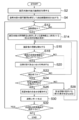
- FIG. 6 is a flowchart showing the flow of processing for an example of an interpretation support method using the interpretation support apparatus of the first embodiment. This process is executed by the CPU 29 according to a program stored in advance in the storage unit 28.
- the medical image to be interpreted is acquired from the database 16 by the communication unit 21 (step S2).
- the lesion candidate site extraction unit 31 analyzes the medical image to be interpreted and extracts a lesion candidate site from the medical image to be interpreted (step S4).
- the lesion candidate site extraction unit 31 creates support information indicating the lesion candidate site.
- the marks 52A and 52B (support information) shown in FIG. 3 or the marks 54A and 54B (support information) shown in FIG. 4 are created based on the analysis result of the medical image.
- “extract a lesion candidate site” recognizes an image of a portion (a lesion candidate site) that may be a lesion site in a medical image by image processing, and at least a lesion in the medical image.
- Information indicating the position of the candidate part is created as support information.
- the marks 52A and 52B formed of closed curves shown in FIG. 3 are created as support information, not only the representative position (for example, the center position) of the lesion candidate site, but also the contour of the lesion candidate site (or the lesion candidate site) Information for specifying a circumscribed figure) or the size of a candidate lesion site is recognized by image processing, and support information is created.
- step S12 it is determined whether or not the image interpreter starts to interpret the medical image to be interpreted.
- the instruction input unit 23 receives an input of a start instruction from an interpreter. That is, it is detected that the interpreter intends to start interpretation.
- the display control unit 36 displays the medical image to be interpreted on the display unit 24 and hides the support information from the display unit 24 (step S12). S14). That is, the display control unit 36 sets the first display state on the display unit 24.
- the gaze detection unit 32 detects the gaze of the radiogram interpreter (step S16).
- step S18 based on the detection result of the eye gaze detection unit 32, it is determined whether or not the eye gaze of the interpreter is directed to the lesion candidate site of the medical image to be interpreted displayed on the display unit 24 (step S18).
- the gaze determination unit 33 determines whether the interpreter is in the gaze state of gazing at the lesion candidate site. It is determined whether or not it is in a non-gaze state in which the line of sight is directed to the lesion candidate site but the lesion candidate site is not watched (step S20).
- step S22 based on the detection result of the end detection unit 35, it is determined whether or not the interpretation of the medical image to be interpreted is complete (step S22).
- the instruction input unit 23 receives an input of an end instruction from a radiogram interpreter. That is, it is detected that the interpreter intends to end the interpretation.
- steps S16 to S22 are repeated.
- step S24 it is determined whether or not a candidate lesion site has been watched after the start of interpretation.
- Step S26 the display control unit 36 maintains the first display state of the display unit 24.
- the display control unit 36 does not display the support information.
- the display unit 24 may be switched to a display state different from the first display state.
- the end detection unit 35 detects the end of interpretation and the gaze determination unit 33 determines that the candidate lesion site has not been observed after the start of interpretation (NO in step S24)
- the support information is displayed on the display unit 24 ( Step S28). That is, the display control unit 36 switches the display unit 24 from the first display state to the second display state.
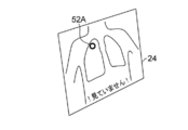
- the marks 52A and 52B shown in FIG. 3 are created as support information, as shown in FIG. 7, the marks 52A and 52B are not displayed in the first display state, but in the second display state. Marks 52A and 52B are displayed. In FIG. 7, a message “! I have not seen!” Is displayed on the display unit 24 together with the marks 52 ⁇ / b> A and 52 ⁇ / b> B.
- the process After setting the second display state, the process returns to step S16, and the interpretation is restarted by the interpreter. In this example, the interpretation is resumed in the second display state.
- the display unit 24 may be returned to the first display state in response to an instruction input by the interpreter or after a predetermined time has elapsed.
- the end detection unit 35 detects the end of interpretation and the gaze determination unit 33 determines that the candidate lesion site has been observed after the start of interpretation (in the case of YES in step S24), the support information on the display unit 24 is not displayed.
- the instruction input unit 23 receives an input of the interpretation result from the interpreter, and creates an interpretation report (step S30).
- the created interpretation report is transmitted to the database 16 by the communication unit 21 and stored in the database 16.
- step S32 it is determined whether or not there is an uninterpreted medical image among the medical images to be interpreted in the database 16 (step S32). If it is determined that there is an uninterpreted medical image (YES in step S32), the process returns to step S12 so that the image interpreter can interpret the next medical image. If it is determined that there is no unread medical image (NO in step S32), the process ends.
- FIG. 7 is used to simplify the case where there is even one unfocused lesion candidate site when the interpreter intends to end the interpretation (NO in step S24 in FIG. 6). Although an example in which all the support information is displayed has been described, the present invention is not limited to such a case.
- the display control unit 36 displays the second display state.
- a mark for example, mark 52B
- the image reader indicates an unwatched lesion candidate site. Only the mark (for example, the mark 52A) is displayed on the display unit 24.
- the image reader can intuitively understand the relationship between the eye movement and the areas that have been watched and the areas that have not been watched. It is preferable to do.
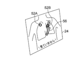
- the display control unit 36 displays the time series of the interpreter. In accordance with the movement of the line of sight, the display mode of the lesion candidate site that has been watched by the interpreter among the plurality of lesion candidate sites is changed. For example, as shown in FIG.
- the display control unit 36 changes the color or pattern of the watched area 56 including the watched lesion candidate part in the medical image to be read into the time-series eye movement of the interpreter. Change to chronological order.
- the display control is performed in such an interaction that the gazed area 56 is gradually erased with an eraser in accordance with the movement of the line of sight.
- display control such as dimming the display of the watched area 56 or setting it to halftone.
- an interpreter can recognize the unfocused lesion candidate site and the watched lesion candidate site separately.
- the display mode of the candidate part is changed.
- “change the display mode of the gazed lesion candidate site” includes the display of the gazed region 56 including the gazed lesion candidate site in the medical image to be interpreted. The case of changing the aspect is included.
- the display control unit 36 may enlarge and display the region of the medical image to be interpreted that is line of sight.
- the display control unit 36 based on the result of the line-of-sight detection by the line-of-sight detection unit 32, corresponds to the region corresponding to the line-of-sight position in the medical image to be interpreted (for example, within a circle with a certain radius centered on the line-of-sight position). Zoom in on (area) only.
- the display control unit 36 stops the enlarged display of a region (for example, a region outside a circle with a constant radius centered on the line-of-sight position) that is distant from the line-of-sight position in the medical image to be interpreted. The enlarged display may be stopped after a certain time has elapsed since the enlarged display was started.
- the display control unit 36 may perform display control in which the visibility of a portion that does not require gaze in the medical image to be interpreted is lower than that of the lesion candidate site.
- the display control unit 36 performs display control such that a portion (part other than the lesion candidate) of the medical image excluding the lesion candidate portion is dimmed or halftone.
- the peripheral part of the lesion candidate site for example, a part within a certain distance from the lesion candidate site
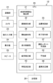
- FIG. 10 is a block diagram illustrating a configuration example of the image interpretation support device 12 according to the second embodiment of the present invention.
- symbol is attached
- the fatigue estimation unit 41 estimates whether it is necessary to recover the interpreter's fatigue by the interpretation of the interpreter.
- the warning unit 42 outputs a warning to the radiogram interpreter when it is estimated by the fatigue estimation unit that recovery of the radiographer's fatigue is necessary.
- the fatigue estimation unit 41 of this example is the number of times the display control unit 36 switches from the first display state (in which support information is not displayed) to the second display state (in which support information is displayed). Based on the above, it is estimated whether recovery from fatigue is necessary. Other aspects of fatigue estimation will be described later.
- the warning output by the warning unit 42 may be performed using the display unit 24 or the speaker 25.
- the warning output from the speaker 25 may be a human voice output or a warning sound output.
- the warning output is not limited to visual output or auditory output, and may be tactile output (for example, generation of vibration).
- FIG. 11 is a flowchart showing the flow of processing for an example of an interpretation support method using the interpretation support apparatus 12 of the second embodiment. This process is executed by the CPU 29 according to a program stored in advance in the storage unit 28.
- the same steps as those in the first embodiment shown in FIG. 6 are denoted by the same reference numerals, and only different items will be described below.
- the display control unit 36 After switching the display state from the first display state (in which support information is not displayed) to the second display state (in which support information is displayed) by control (step S28), The number of times of switching from the first display state to the second display state is compared with the threshold value (step S42).
- “comparison” may be performed by counting the number of switching for each page of the medical image to be interpreted and comparing it with a threshold value.
- the total number of times of switching for each predetermined number of pages may be compared with a threshold value, or the total number of times of switching over an indefinite number of pages may be compared with the threshold value.
- step S42 When the number of times of switching from the first display state to the second display state is equal to or less than the threshold value (in the case of NO in step S42), the process returns to step S16 and the interpretation is resumed.
- step S42 When the number of times of switching from the first display state to the second display state exceeds the threshold value (in the case of YES in step S42), at least one of the display unit 24 and the speaker 25 in this example is controlled by the warning unit 42. Is used to output a warning (step S44).
- this process ends and the interpretation is interrupted. After the warning is output, the interpretation may be resumed at the judgment of the interpreter. That is, the process returns to step S12 in FIG.
- ⁇ Variation of fatigue estimation Referring to FIG. 11, based on the number of times of switching from the first display state to the second display state (that is, the number of times that the interpreter tried to end the interpretation but it was determined that there was an unfocused lesion candidate site). Although an embodiment has been described in which it is determined whether or not a warning output is to be output (that is, whether or not it is necessary to recover an observer's fatigue), the present invention is not limited to such a case. For example, the following variations 1 to 3 may be performed.
- Fatigue estimation is performed based on the cumulative interpretation time of the interpreter. For example, using a built-in timer in the CPU 29 (or a timer provided as a peripheral device of the CPU 29), the fatigue estimation unit 41 calculates the accumulated time from the start of interpretation to the end of interpretation and compares it with a threshold value.
- “cumulative time” preferably uses a cumulative value of interpretation time over a plurality of pages of medical images that have been continuously interpreted by the interpreter. For example, the cumulative value of the interpretation time over the number of indefinite pages that have been continuously interpreted is compared with a threshold value.
- Fatigue estimation is performed based on at least one of the movement speed and movement amount of the sight line of the interpreter.
- the fatigue estimation unit 41 calculates at least one of the movement speed and movement amount of the interpreter's line of sight based on the result of the line-of-sight detection of the line-of-sight detection unit 32 and compares it with a threshold value.
- the “movement speed” and the “movement amount” may be calculated values in a medical image that is currently directed at the line of sight, or may be an average of calculated values over a plurality of pages of medical images that have been continuously read by the interpreter. .
- the average value (moving average) of the movement speed of the line of sight for every certain number of pages that have been read continuously is compared with a threshold value.
- Fatigue estimation is performed based on the blinking speed of the interpreter's eyes.
- a blink detection unit 38 is added, and the blink detection unit 38 detects blinks of the eyes of the interpreter based on the interpreter image captured by the camera 22.
- the fatigue estimation unit 41 calculates the eye blinking speed of the interpreter, compares it with a threshold, and estimates that the interpreter needs to recover from fatigue when the eye blinking speed is less than the threshold. . In this mode, the human characteristic that the blinking speed becomes slower when not tired than when not fatigued is used.
- the time length of one blink is calculated from the time when the line of sight does not hit anywhere in the medical image, and fatigue estimation is performed by comparing with a threshold value.
- the blink detection unit 38 performs blink detection based on the output of the line-of-sight detection unit 32.
- variation of fatigue estimation in the present invention is not particularly limited to the above-described variations 1 to 3. Further, the accuracy of fatigue estimation may be improved by combining various variations.
- FIG. 13 is a block diagram illustrating a configuration example of the image interpretation support device 12 according to the third embodiment of the present invention.
- symbol is attached
- the characteristic measurement unit 43 measures the characteristic of the reader's gaze for each individual.
- the reference determination unit 44 is a reference for determining whether it is a gaze state or a non-gaze state based on the result of measurement for each individual by the characteristic measurement unit 43 (data for each individual of the radiogram interpreter).
- the criteria for estimating whether or not the reader needs to recover from fatigue are determined for each individual.
- the gaze determination unit 33 determines whether the radiogram interpreter is in a gaze state or a non-gaze state based on a determination criterion determined for each individual by the reference determination unit 44. Further, the fatigue estimation unit 41 of the present embodiment estimates whether or not it is necessary to recover the interpreter's fatigue based on the criteria determined for each individual by the criteria determination unit 44.
- the characteristic measuring unit 43 displays, for example, a test pattern for causing the display unit 24 to measure individual characteristics on the first screen on which the execution of a program for supporting interpretation is started, and moves the test pattern on the screen. Measure the follower's line of sight to the movement of the pattern.
- the reference determination unit 44 determines a reference for determining whether the user is in the gaze state or in the non-gaze state based on the followability of the eyesight of the interpreter measured by the characteristic measurement unit 43. Further, the reference determination unit 44 determines a reference for estimating whether or not fatigue recovery is necessary based on the followability of the line of sight of the interpreter measured by the characteristic measurement unit 43.
- the characteristic measurement mode of the characteristic measurement unit 43 is not particularly limited when the above-described test pattern is used.
- the display of the test pattern is not performed, and the characteristic measurement may be performed based on at least one of the line-of-sight movement and the eye state change of the interpreter during interpretation.
- “Determination of the reference for each individual” by the reference determination unit 44 includes a case where a predetermined reference value is automatically adjusted for each radiogram interpreter.
- FIG. 14 is a block diagram illustrating a configuration example of the image interpretation support device 12 according to the fourth embodiment of the present invention. Note that the same components as those in the image interpretation support device 12 of the third embodiment shown in FIG. 13 are denoted by the same reference numerals, and description of the contents already described is omitted below.
- the image interpretation estimation unit 39 estimates whether or not an image interpreter has performed an interpretation from an enlargement operation of a medical image to be interpreted.
- the end detection unit 35 detects that the interpretation is completed only when the interpretation estimation unit 39 estimates that the interpretation has been performed. That is, even when the radiographer intends to end the interpretation, the detection accuracy of the interpretation end can be improved by excluding the case where it is estimated that the interpretation is not actually performed.
- the image interpretation support device 12 may be configured by a plurality of devices, and the processing necessary for image interpretation support may be distributed among these devices. That is, the image interpretation support device 12 shown in FIG. 1 may be configured by a plurality of devices.
- FIG. 15 shows a system configuration example in which the image interpretation support device 12 shown in FIG. 1 is composed of a medical image analysis device 13 and an image interpreter terminal 14.
- the medical image analysis apparatus 13 includes a lesion candidate site extraction unit 31 (31 in FIG. 2, FIG. 10, FIG. 12, FIG. 13 or FIG. 14).
- the radiogram interpreter terminal 14 is a terminal operated by the radiogram interpreter.
- the radiogram interpreter terminal 14 may be an apparatus having a configuration in which the lesion candidate site extraction unit 31 is omitted from the radiogram interpretation support apparatus 12 described in the first to fourth embodiments.
- the communication unit 21 of the radiogram interpreter terminal 14 acquires, via communication, the medical image to be interpreted and the support information indicating the candidate lesion site extracted from the medical image from the database 16 via the local area network 18. .
Abstract
The purpose of the present invention is to provide a radiograph interpretation assistance device and method which prevent areas of a radiograph to be interpreted from being overlooked by a radiologist without interfering with the radiologist's interpretation. Provided is a radiograph interpretation assistance device, comprising: a sight line sensing unit (32) which senses the sight line of a radiologist; a focus assessment unit (33) which assesses, on the basis of the result of the sensing by the sight line sensing unit, whether a lesion candidate site within an image of the radiograph to be interpreted which is displayed by a display unit (24) has been focused upon by the radiologist; a termination sensing unit (35) which senses a termination of the radiological interpretation by the radiologist of the image of the radiograph to be interpreted which is displayed by the display unit; and a display control unit which switches from a first display state in which the image of the radiograph to be interpreted is displayed by the display unit and in which assistance information is not displayed to a second display state in which at least the assistance information is displayed by the display unit, if the termination of the radiological interpretation is sensed by the termination sensing unit and it is assessed by the focus assessment unit that the lesion candidate site has not been focused upon.
Description
本発明は読影支援装置及び方法に係り、特に読影者の読影を妨げることなく読影者の見落としを防ぐことができる読影支援の技術に関する。
The present invention relates to an interpretation support apparatus and method, and more particularly, to an interpretation support technique that can prevent oversight of an interpreter without interfering with the interpretation of the interpreter.
読影医は、一日に大量の医用画像(例えばエックス線画像)を読影することがある。近年、熟練した読影医の不足がおきており、読影医の負担が増える傾向にある。特に、定期検診の医師や遠隔読影専門の医師は、短い時間で読影する必要がある為、病変部位の見落としの危険性が高くなる。そのような病変部位の見落としを防ぐ技術として、画像処理によって読影対象の医用画像中に存在する陰影等の病変候補部位の自動認識を行い、その病変候補部位を示すマーク(支援情報)を医用画像上に表示することによって、読影対象の医用画像中のどの部分を注視すべきかを読影中に読影医に知らせる技術が知られている(特許文献1)。
An interpreting doctor may interpret a large amount of medical images (for example, X-ray images) per day. In recent years, there has been a shortage of skilled interpreting doctors, and the burden on interpreting doctors tends to increase. In particular, regular doctors and doctors specializing in remote interpretation need to interpret in a short time, which increases the risk of overlooking the lesion site. As a technique for preventing such an oversight of a lesion site, a lesion candidate site such as a shadow existing in a medical image to be interpreted is automatically recognized by image processing, and a mark (support information) indicating the lesion site is used as a medical image. A technique is known in which an image interpretation doctor is notified during interpretation of which part of a medical image to be interpreted is to be watched by displaying it above (Patent Document 1).
また、両手がふさがっている医療現場で、音声、視線、あるいはジェスチャにより、何も触れずに指示入力することを可能にした医療機器が提案されている(特許文献2、3)。
In addition, there has been proposed a medical device capable of inputting instructions without touching anything by voice, line of sight, or gesture in a medical field where both hands are occupied (Patent Documents 2 and 3).
しかしながら、読影者の読影を妨げることなく読影者の見落としを防ぐことは困難である。
However, it is difficult to prevent oversight of the interpreter without interfering with the interpretation of the interpreter.
なぜなら、特許文献1に記載された技術を用いて、病変候補部位を示す支援情報を医用画像の上に表示してしまうと、読影者が無意識のうちの支援情報に頼りすぎて読影者の自律した読影が阻害されるという課題や、支援情報の下に病変部位が隠れて見えなくなり読影者の読影を邪魔してしまうという課題があった。これらの課題を解決するため、病変候補部位に被らないように支援情報を表示する方法や、医師の判断によって支援情報の表示/非表示の切り替え操作を行えるようにする方法が考えられるが、画像の表示領域が狭くなる、切り替え操作の手間が掛かる、といった新たな問題が生じる。そのため、短い時間で確実に読影することが求められるシーンで、読影者の読影を妨げることなく読影者の見落としを防ぐ課題に対して、有効な方法であるとは言い難い。
This is because if the support information indicating the candidate lesion site is displayed on the medical image using the technique described in Patent Document 1, the interpreter relies too much on the unconscious support information and the interpreter's autonomous There is a problem that the interpretation is obstructed, and a problem is that the lesion site is hidden under the support information so that it cannot be seen and obstructs the interpretation of the interpreter. In order to solve these problems, there are a method of displaying support information so that it does not cover a candidate lesion site, and a method of enabling switching operation of displaying / hiding support information according to a doctor's judgment. New problems arise, such as a reduction in the display area of the image and a time-consuming switching operation. Therefore, it is difficult to say that this is an effective method for the problem of preventing oversight of an interpreter without interfering with the interpretation of the interpreter in a scene that is required to be reliably interpreted in a short time.
特許文献2に記載された技術は、音声入力及び視線入力の組み合わせで拡大/縮小等の画像操作を行う構成であって、音声入力が必要なので、他者の声やBGM(Back Ground Music)等の騒音がある環境では確実な操作を行うことができない。また、何も触れずに指示入力できるにしても、指示入力の手間が掛かることに変わりがない。
The technique described in Patent Document 2 is a configuration in which image operations such as enlargement / reduction are performed by a combination of voice input and line-of-sight input, and voice input is necessary, so that the voice of another person, BGM (Back Ground Music), etc. Certain operations cannot be performed in an environment with a high level of noise. Moreover, even if the instruction can be input without touching anything, it still takes time to input the instruction.
特許文献3に記載された技術は、表示されたアイコンに視線位置を移動して所定時間注視することによってアイコンに対応したコマンドを実行する構成であって、アイコンに視線位置を移動させる必要があるので読影者の読影を妨げない効果を期待することができない。また、読影者の見落としを防ぐ効果も期待することができない。
The technique described in Patent Document 3 is configured to execute a command corresponding to an icon by moving the line-of-sight position to the displayed icon and gazing for a predetermined time, and it is necessary to move the line-of-sight position to the icon. Therefore, it is not possible to expect an effect that does not interfere with the interpretation of the reader. Moreover, the effect which prevents an overlooker's oversight cannot be expected.
本発明はこのような事情に鑑みてなされたもので、読影者の読影を妨げることなく読影者の見落としを防ぐことができる読影支援装置及び方法を提供することを目的とする。
The present invention has been made in view of such circumstances, and an object thereof is to provide an interpretation support apparatus and method capable of preventing an overlooker from overlooking without disturbing the interpretation of the interpreter.
上記目的を達成するために本発明の一の態様に係る読影支援装置は、読影対象の画像を解析して読影対象の画像から病変候補部位を抽出する病変候補部位抽出部と、読影対象の画像と病変候補部位を示す支援情報とを表示可能な表示部と、読影者の視線を検知する視線検知部と、視線検知部の検知の結果に基づいて、表示部に表示された読影対象の画像のうちの病変候補部位が読影者により注視されたか否かを判別する注視判別部と、表示部に表示された読影対象の画像に対する読影者の読影の終了を検知する終了検知部と、終了検知部により読影の終了が検知され且つ注視判別部により病変候補部位が注視されなかったと判別された場合には、読影対象の画像を表示部に表示し且つ支援情報が非表示である第1の表示状態から、表示部に少なくとも支援情報を表示した第2の表示状態に切り替える表示制御部と、を備える読影支援装置である。
In order to achieve the above object, an interpretation support apparatus according to an aspect of the present invention includes a lesion candidate part extraction unit that analyzes an image to be interpreted and extracts a candidate lesion part from the image to be interpreted, and an image to be interpreted. And an image of the interpretation target displayed on the display unit based on the detection result of the gaze detection unit, the gaze detection unit that detects the gaze of the image interpreter , A gaze determination unit that determines whether or not a candidate lesion site has been watched by an interpreter, an end detection unit that detects the end of the interpretation of the image reader on the image to be interpreted displayed on the display unit, and an end detection A first display in which an image to be interpreted is displayed on the display unit and support information is not displayed when the end of the interpretation is detected by the unit and the gaze determination unit determines that the candidate lesion site has not been watched From state to display A display control unit to switch to a second display state displaying support information even without a interpretation support apparatus comprising a.
表示制御部は、終了検知部により読影の終了が検知され且つ注視判別部により病変候補部位が注視されたと判別された場合には、第1の表示状態を維持するようにしてよい。
The display control unit may maintain the first display state when the end detection unit detects the end of the interpretation and the gaze determination unit determines that the lesion candidate site has been watched.
表示制御部は、終了検知部により読影の終了が検知され且つ注視判別部により病変候補部位が注視されたと判別された場合、支援情報が非表示であり且つ第1の表示状態とは異なる表示状態に表示部を切替えてもよい。
When the end detection unit detects the end of the interpretation and the gaze determination unit determines that the lesion candidate site has been watched, the display control unit displays the support information that is not displayed and is different from the first display state. The display unit may be switched.
本態様の「読影の終了が検知され」は、読影者からの読影終了を示す指示入力(例えばマニュアル操作、音声入力、ジェスチャ等)を検知する場合に特に限定されず、読影者からの読影終了を示す明示的な指示入力が無くても、読影者が読影終了を意図していることを検知又は推定する場合(例えば読影者を撮像して得られた読影者画像を画像処理により解析して検知又は推定を行う場合)を含む。
The “detection of the end of interpretation” in this aspect is not particularly limited to detecting an instruction input (for example, manual operation, voice input, gesture, etc.) indicating the end of interpretation from the interpreter, and the end of interpretation from the interpreter. Even if there is no explicit instruction input indicating that the radiogram reader detects or estimates that the radiographer intends to end the radiogram interpretation (for example, the image of the radiographer obtained by imaging the radiographer is analyzed by image processing) Detection or estimation).
本態様によれば、終了検知部により読影の終了が検知され且つ注視判別部で病変候補部位が注視されたと判別された場合には支援情報の非表示が維持される一方で、終了検知部により読影の終了が検知され且つ注視判別部により病変候補部位が注視されなかったと判別された場合には読影者に対して病変候補部位を示す支援情報が表示されるので、読影者は読影中に支援情報に邪魔されることがなく病変部位の注視に集中力を高めることができ、且つ読影終了時に未注視の病変候補部位がある場合にはそのことを知って読影を再開するようになる。つまり、本態様によれば、読影者の読影を妨げることがなく読影者の見落としを防ぐことができる。
According to this aspect, when the end detection unit detects the end of the interpretation and the gaze determination unit determines that the candidate lesion site has been watched, the support information is not displayed, but the end detection unit When the end of the interpretation is detected and the gaze discrimination unit determines that the candidate lesion site has not been gaze, support information indicating the lesion candidate site is displayed to the interpreter, so the interpreter supports during interpretation It is possible to increase concentration on gaze of the lesion site without being obstructed by the information, and when there is a non-gaze lesion candidate site at the end of the interpretation, the interpretation is resumed by knowing that fact. That is, according to this aspect, it is possible to prevent an overlooker's oversight without disturbing the interpreter's interpretation.
本発明の他の態様に係る読影支援装置では、表示制御部は、読影対象の画像に複数の病変候補部位が存在する場合、第2の表示状態において、複数の病変候補部位のうち読影者により注視済の病変候補部位の支援情報を非表示として、読影者により未注視の病変候補部位の支援情報を表示する。本態様によれば、読影者は複数の病変候補部位のうちの未注視の病変候補部位のみに集中して注視することが可能になるので、読影の効率が向上する。
In the image interpretation support apparatus according to another aspect of the present invention, the display control unit, when there are a plurality of lesion candidate sites in the image to be interpreted, is read by the interpreter among the plurality of lesion candidate sites in the second display state. The support information of the non-gazeable lesion candidate site is displayed by the radiogram interpreter while the support information of the gazeable lesion candidate site is not displayed. According to this aspect, it is possible for the image interpreter to concentrate on and focus on only the unfocused lesion candidate sites among the plurality of lesion candidate sites, so that the efficiency of image interpretation is improved.
本発明の他の態様に係る読影支援装置では、表示制御部は、読影対象の画像に複数の病変候補部位が存在する場合、複数の病変候補部位のうち読影者により注視済の病変候補部位の表示態様を変更することで読影者により未注視の病変候補部位と区別して表示する。本態様によれば、読影者は、自身の視線移動に応じて表示態様が変更される注視済の病変候補部位を除いて、表示態様が維持される未注視の病変候補部位のみに集中して注視することが可能になる。つまり、読影者の視線移動に対してインタラクティブに反応する表示制御が行われることにより、読影の効率が向上する。
In the image interpretation support apparatus according to another aspect of the present invention, the display control unit, when there are a plurality of lesion candidate sites in the image to be interpreted, includes the candidate lesion sites that have been watched by the interpreter among the plurality of lesion candidate sites. By changing the display mode, it is displayed separately from the candidate lesion site that has not been gazed by the radiogram interpreter. According to this aspect, the radiogram interpreter concentrates on only the non-gazing lesion candidate sites in which the display mode is maintained, except for the gaze candidate lesion sites in which the display mode is changed according to his / her own line of sight movement. It becomes possible to watch. In other words, interpretation control is improved by performing display control that interactively reacts to the eye movement of the interpreter.
本発明の他の態様に係る読影支援装置では、読影者の読影による疲労の回復が必要であるか否かを推定する疲労推定部と、疲労推定部により疲労の回復が必要であると推定された場合、警告を出力する警告部と、を備える。本態様によれば、読影者が疲労している場合に読影者の休養が促されることになる。つまり、読影者が集中力を保つことが可能になる。
In the image interpretation support apparatus according to another aspect of the present invention, it is estimated that the fatigue estimation unit that estimates whether or not the fatigue recovery by the interpretation of the image interpreter is necessary, and the fatigue estimation unit needs to recover the fatigue. A warning unit for outputting a warning in the case of a warning. According to this aspect, when the radiographer is tired, resting of the radiographer is prompted. In other words, it is possible for the image reader to keep his concentration.
本発明の他の態様に係る読影支援装置では、疲労推定部は、表示制御部による第1の表示状態から第2の表示状態への切替回数に基づいて、疲労の回復が必要であるか否かを推定する。
In the image interpretation support apparatus according to another aspect of the present invention, the fatigue estimation unit determines whether it is necessary to recover from fatigue based on the number of times the display control unit switches from the first display state to the second display state. Estimate.
本発明の他の態様に係る読影支援装置では、疲労推定部は、読影の時間の累積に基づいて、疲労の回復が必要であるか否かを推定する。
In the interpretation support apparatus according to another aspect of the present invention, the fatigue estimation unit estimates whether or not fatigue recovery is necessary based on the accumulation of interpretation time.
本発明の他の態様に係る読影支援装置では、疲労推定部は、視線検知部により検知された視線の移動速度及び移動量のうちの少なくとも一方に基づいて、疲労の回復が必要であるか否かを推定する。
In the image interpretation support device according to another aspect of the present invention, the fatigue estimation unit needs to recover from fatigue based on at least one of the line-of-sight movement speed and the amount of movement detected by the line-of-sight detection unit. Estimate.
本発明の他の態様に係る読影支援装置では、読影者の目の瞬きを検知する瞬き検知部を備え、疲労推定部は、目の瞬きの速度に基づいて、疲労の回復が必要であるか否かを推定する。本態様によれば、疲労していないのに個人的な特性に因り疲労していると誤判断する可能性を低減させることになる。つまり、誤判断による警告の出力を低減することができる。
In the image interpretation support device according to another aspect of the present invention, the image interpretation support device includes a blink detection unit that detects blinks of the interpreter, and is the fatigue estimation unit required to recover from fatigue based on the blink rate of the eyes? Estimate whether or not. According to this aspect, it is possible to reduce the possibility of erroneous determination that the user is fatigued due to personal characteristics even though he is not fatigued. That is, it is possible to reduce the output of a warning due to erroneous determination.
本発明の他の態様に係る読影支援装置では、疲労推定部は、読影者の個人ごとのデータに基づいて、疲労の回復が必要であるか否かを推定する。
In the interpretation support apparatus according to another aspect of the present invention, the fatigue estimation unit estimates whether or not it is necessary to recover from fatigue based on data for each individual of the interpreter.
本発明の他の態様に係る読影支援装置では、表示制御部は、読影対象の画像のうちの視線が向けられている領域を拡大表示し、視線が外れた場合、又は拡大表示を開始してから一定時間経過後に、拡大表示を止める。
In the image interpretation support apparatus according to another aspect of the present invention, the display control unit enlarges and displays an area to which the line of sight of the image to be interpreted is directed, and starts the enlarged display when the line of sight is off. After a certain amount of time has elapsed, the enlarged display is stopped.
本発明の他の態様に係る読影支援装置では、表示制御部は、読影対象の画像のうちの病変候補部位よりも注視が不要な部分の視認性を低くする。
In the image interpretation support apparatus according to another aspect of the present invention, the display control unit lowers the visibility of a portion that does not require gaze than the lesion candidate site in the image to be interpreted.
本発明の他の態様に係る読影支援装置では、視線検知部の視線検知により読影者からの指示入力を受け付ける。
In the image interpretation support apparatus according to another aspect of the present invention, an instruction input from the image interpreter is received by the line-of-sight detection of the line-of-sight detection unit.
本発明の他の態様に係る読影支援装置では、注視判別部は、表示部に表示された読影対象の画像の病変候補部位に読影者の視線が向けられている場合に、読影者が病変候補部位を注視した注視状態であるか、読影者が病変候補部位に視線を向けているが病変候補部位を注視していない非注視状態であるか、を判別する。
In the image interpretation support apparatus according to another aspect of the present invention, the gaze determination unit determines whether the image interpreter is a lesion candidate when the image reader's line of sight is directed to the lesion candidate site of the image to be interpreted displayed on the display unit. It is determined whether the state is a gaze state in which the region is gazeed or whether the image reader is in a non-gaze state in which the gaze is directed to the lesion candidate region but not in the lesion candidate region.
本発明の他の態様に係る読影支援装置では、注視判別部は、病変候補部位への読影者の視線の滞留時間に基づいて、注視状態であるか、非注視状態であるか、を判別する。
In the image interpretation support apparatus according to another aspect of the present invention, the gaze determination unit determines whether the gaze state is in the gaze state or the non-gaze state based on the dwell time of the interpreter's line of sight to the candidate lesion site. .
本発明の他の態様に係る読影支援装置では、注視判別部は、読影者の瞳の状態に基づいて、注視状態であるか、非注視状態であるか、を判別する。
In the image interpretation support device according to another aspect of the present invention, the gaze determination unit determines whether it is a gaze state or a non-gaze state based on the state of the pupil of the interpreter.
本発明の他の態様に係る読影支援装置では、読影者の注視の特性を個人ごとに測定する特性測定部と、特性測定部による個人ごとの測定の結果に基づいて、注視状態であるか、非注視状態であるか、の判別の基準を個人ごとに決定する基準決定部と、を備え、注視判別部は、基準決定部により個人ごとに決定された判別の基準に基づいて、読影者が注視状態であるか、非注視状態であるか、を判別する。
In the image interpretation support apparatus according to another aspect of the present invention, whether or not a gaze state is based on a result of measurement for each individual by the characteristic measurement unit and a characteristic measurement unit that measures the characteristic of the gaze of the interpreter for each individual, A standard determination unit that determines, for each individual, a criterion for determining whether or not the subject is in a non-gaze state, and the gaze determination unit determines whether the reader is based on the criterion for determination determined for each individual by the standard determination unit. It is determined whether it is a gaze state or a non-gaze state.
本発明の他の態様に係る読影支援装置では、特性測定部は、表示部にテストパターンを表示して画面中で移動させ、テストパターンの移動に対する読影者の視線の追従性を測定し、注視判別部は、特性測定部により測定された読影者の視線の追従性に基づいて、注視状態であるか、非注視状態であるか、の判別の基準を決定する。
In the image interpretation support apparatus according to another aspect of the present invention, the characteristic measurement unit displays a test pattern on the display unit and moves the test pattern on the screen, measures the followability of the gaze of the interpreter with respect to the movement of the test pattern, and gazes The discriminating unit determines a criterion for discriminating whether it is a gaze state or a non-gaze state based on the followability of the line of sight of the interpreter measured by the characteristic measurement unit.
本発明の一の態様に係る読影支援装置は、読影対象の画像の拡大操作から読影者の読影が行われたか否かを推定する読影推定部を備え、終了検知部は、読影推定部により読影が行われたと推定された場合のみ読影が終了したことを検知する。
An image interpretation support apparatus according to an aspect of the present invention includes an image interpretation estimation unit that estimates whether or not an image interpreter has performed an interpretation from an enlargement operation of an image to be interpreted, and the end detection unit is interpreted by the image interpretation estimation unit. Only when it is estimated that the interpretation has been performed, it is detected that the interpretation has ended.
本発明の一の態様に係る読影支援方法は、読影対象の画像を解析して読影対象の画像から病変候補部位を抽出するステップと、読影対象の画像を表示部に表示し且つ病変候補部位を示す支援情報が非表示である第1の表示状態とするステップと、読影者の視線を検知するステップと、視線の検知の結果に基づいて、表示部に表示された読影対象の画像のうちの病変候補部位が読影者により注視されたか否かを判別するステップと、表示部に表示された読影対象の画像に対する読影者の読影の終了を検知するステップと、読影の終了が検知され且つ病変候補部位が注視されなかったと判別された場合には、読影対象の画像を表示部に表示し且つ支援情報が非表示である第1の表示状態から、表示部に少なくとも支援情報を表示した第2の表示状態に切り替えるステップと、を含む。
An interpretation support method according to an aspect of the present invention includes a step of analyzing an image to be interpreted and extracting a candidate lesion site from the image to be interpreted, displaying an image to be interpreted on a display unit, and selecting a candidate lesion site. Of the image to be interpreted, displayed on the display unit, based on the result of the gaze detection, the step of detecting the gaze of the interpreter, and the step of setting the first display state in which the support information to be displayed is hidden A step of determining whether or not a candidate lesion site has been watched by an interpreter, a step of detecting the end of the interpretation of the interpreter for the image to be interpreted displayed on the display unit, and the end of the interpretation is detected and the candidate lesion When it is determined that the part has not been watched, the second display state in which at least the support information is displayed on the display unit from the first display state in which the image to be interpreted is displayed on the display unit and the support information is not displayed. display Comprising a step of switching to the state, the.
本発明よれば、読影者の読影を妨げることなく読影者の見落としを防ぐことができる。
According to the present invention, an overlooker can be prevented from being overlooked without disturbing the interpreter.
以下、添付図面に従って本発明に係る読影支援装置及び読影支援方法の実施の形態について説明する。
Hereinafter, embodiments of an interpretation support apparatus and an interpretation support method according to the present invention will be described with reference to the accompanying drawings.
<システム構成例>
図1は、本発明に係る読影支援装置を備えた医用システムの一例を示すシステム構成図である。 <System configuration example>
FIG. 1 is a system configuration diagram showing an example of a medical system provided with an image interpretation support apparatus according to the present invention.
図1は、本発明に係る読影支援装置を備えた医用システムの一例を示すシステム構成図である。 <System configuration example>
FIG. 1 is a system configuration diagram showing an example of a medical system provided with an image interpretation support apparatus according to the present invention.
図1に示す医用システムは、モダリティ10と、読影支援装置12と、データベース16とが、ローカルエリアネットワーク18を介して互いに通信可能な状態で接続されて構成されている。
The medical system shown in FIG. 1 includes a modality 10, an image interpretation support device 12, and a database 16 that are connected to each other via a local area network 18 so that they can communicate with each other.
尚、図1は、説明の便宜上、各装置が1台ずつローカルエリアネットワーク18に接続された構成を示しているが、ローカルエリアネットワーク18には、複数かつ多種類のモダリティが接続される。読影支援装置12についても、読影者の人数に応じて複数台接続される。データベース16についても、複数台接続して分散化してよい。
Note that FIG. 1 shows a configuration in which each device is connected to the local area network 18 for convenience of explanation, but a plurality of types of modalities are connected to the local area network 18. A plurality of interpretation support devices 12 are also connected according to the number of interpreters. A plurality of databases 16 may be connected and distributed.
モダリティ10は、被検体(人、動物など)を撮影することにより医用画像のデータを生成し、出力する医用画像撮影装置である。本例のモダリティ10は、医用画像のデータにDICOM(digital imaging and communication in medicine)規格で規定された付加情報を付加する。モダリティ10の具体例としては、X(エックス)線単純撮影装置、CT(computed tomography)撮影装置、MRI(magnetic resonance imaging)撮影装置、PET(positron emission tomography)撮影装置、超音波撮影装置などが挙げられる。
The modality 10 is a medical image photographing apparatus that generates and outputs medical image data by photographing a subject (human, animal, etc.). The modality 10 of this example adds additional information defined by DICOM (digital imaging and communication in medicine) standards to medical image data. Specific examples of the modality 10 include an X-ray simple imaging apparatus, a CT (computed tomography) imaging apparatus, an MRI (magnetic resonance imaging) imaging apparatus, a PET (positron emission tomography) imaging apparatus, and an ultrasonic imaging apparatus. It is done.
読影支援装置12は、読影者による医用画像の読影を支援する装置である。例えば、コンピュータ装置により構成される。具体例は後述する。
The image interpretation support device 12 is a device that supports the interpretation of medical images by an image interpreter. For example, it is configured by a computer device. Specific examples will be described later.
データベース16は、医用画像のデータ、及び医用画像の読影を支援するためのデータ(後述の支援情報のデータなど)を記憶する。
The database 16 stores medical image data and data for supporting interpretation of medical images (such as support information data described later).
<第1実施形態>
図2は、本発明に係る第1実施形態の読影支援装置12の構成例を示すブロック図である。 <First Embodiment>
FIG. 2 is a block diagram illustrating a configuration example of the imageinterpretation support device 12 according to the first embodiment of the present invention.
図2は、本発明に係る第1実施形態の読影支援装置12の構成例を示すブロック図である。 <First Embodiment>
FIG. 2 is a block diagram illustrating a configuration example of the image
本実施形態の読影支援装置12は、ローカルエリアネットワーク18に接続された各装置(例えばデータベース16)と通信可能である通信部21と、読影者を撮像して読影者の画像(以下「読影者画像」という)を出力するカメラ22と、読影者から指示入力を受け付ける指示入力部23と、読影者に対して表示を行う表示部24と、読影を支援するためのプログラム及びそのプログラムの実行に必要な情報を記憶する記憶部28と、記憶部28に記憶されたプログラムに従って読影支援装置12の各部を制御するCPU(central processing unit)29を備える。
The image interpretation support device 12 of the present embodiment includes a communication unit 21 that can communicate with each device (for example, the database 16) connected to the local area network 18 and an image of the image reader (hereinafter referred to as “interpreter”). A camera 22 that outputs an image), an instruction input unit 23 that receives an instruction input from an interpreter, a display unit 24 that displays an image to the interpreter, a program for supporting interpretation, and execution of the program A storage unit 28 that stores necessary information, and a CPU (central processing unit) 29 that controls each unit of the image interpretation support device 12 according to a program stored in the storage unit 28 are provided.
本実施形態のCPU29は、通信部21によりデータベース16から取得された読影対象の医用画像を解析して、その読影対象の医用画像から病変候補部位を抽出する病変候補部位抽出部31と、カメラ22により撮像された読影者画像に基づいて読影者の視線を検知することにより、表示部24に表示された読影対象の医用画像のうちの読影者が視線を向けている位置(以下「視線位置」という)を算出する視線検知部32と、視線検知部32の検知の結果に基づいて、表示部24に表示された読影対象の医用画像のうちの病変候補部位が読影者により注視されたか否かを判別する注視判別部33と、表示部24に表示される読影対象の医用画像に対する読影者の読影の開始を検知する開始検知部34と、表示部24に表示される読影対象の医用画像に対する読影者の読影の終了を検知する終了検知部35と、病変候補部位抽出部31の抽出結果、視線検知部32の検知結果、注視判別部33の判別結果、開始検知部34の検知結果、及び終了検知部35の検知結果に基づいて、表示部24の表示を制御する表示制御部36と、指示入力部23に入力された読影者の読影結果などに基づいて読影レポートを作成する読影レポート作成部37を備える。
The CPU 29 of this embodiment analyzes a medical image to be interpreted acquired from the database 16 by the communication unit 21 and extracts a lesion candidate site extracting unit 31 that extracts a lesion candidate site from the medical image to be interpreted, and a camera 22. By detecting the gaze of the radiographer based on the image of the radiographer imaged by, the position of the radiographer in the medical image to be interpreted displayed on the display unit 24 (hereinafter referred to as “gaze position”). And whether or not a candidate lesion site in the medical image to be interpreted displayed on the display unit 24 has been watched by the interpreter based on the detection result of the gaze detection unit 32 and the gaze detection unit 32. A gaze determining unit 33 for detecting the image, a start detecting unit 34 for detecting the start of interpretation by the image interpreter for the medical image to be interpreted displayed on the display unit 24, and an interpretation pair displayed on the display unit 24. The end detection unit 35 for detecting the end of the interpretation of the radiographer for the medical image, the extraction result of the lesion candidate site extraction unit 31, the detection result of the gaze detection unit 32, the determination result of the gaze determination unit 33, and the start detection unit 34 Based on the detection result and the detection result of the end detection unit 35, an interpretation report is created based on the display control unit 36 that controls the display of the display unit 24 and the interpretation result of the interpreter input to the instruction input unit 23. An interpretation report creating unit 37 is provided.
表示部24は、表示制御部36の表示制御に従って、読影対象の医用画像と病変候補部位を示す支援画像とを必要に応じて表示可能である。
The display unit 24 can display a medical image to be interpreted and a support image indicating a lesion candidate site as necessary according to display control of the display control unit 36.
次に、病変候補部位抽出部31により抽出される支援情報の具体例について説明する。
Next, a specific example of the support information extracted by the lesion candidate site extraction unit 31 will be described.
図3は、表示部24に表示された医用画像50に、病変候補部位を示す目印として、各病変候補部位の全部又は一部を囲む閉曲線からなるマーク52A、52Bを重ねて表示した様子を示す。本例では、閉曲線からなるマーク52A、52Bが支援情報である。閉曲線として、例えば病変候補部位に外接する図形(例えば円あるいは多角形)の枠を用いる。
FIG. 3 shows a state in which marks 52A and 52B made up of closed curves surrounding all or a part of each lesion candidate site are superimposed and displayed on the medical image 50 displayed on the display unit 24 as a mark indicating the lesion candidate site. . In this example, marks 52A and 52B made of closed curves are support information. As the closed curve, for example, a frame of a figure (for example, a circle or a polygon) circumscribing a lesion candidate site is used.
図4は、表示部24に表示された医用画像50に、病変候補部位を示す目印として、各病変候補部位を指し示す矢印からなるマーク54A、54Bを重ねて表示した様子を示す。本例では、矢印からなるマーク54A、54Bが支援情報である。
FIG. 4 shows a state in which marks 54A and 54B made up of arrows indicating each lesion candidate site are displayed on the medical image 50 displayed on the display unit 24 as a mark indicating the lesion candidate site. In this example, marks 54A and 54B made of arrows are support information.
尚、図3及び図4では医用画像50の中に病変候補部位が二つ存在する場合を示したが、医用画像50の中の病変候補部位の数は被検体の状態に応じて異なる。つまり、医用画像50に付加される支援情報の一例としてのマークの数は、二つに限定されるわけではなく、一つの場合もあれば、三つ以上の場合もあり、ゼロ個の場合もある。
3 and 4 show the case where there are two lesion candidate sites in the medical image 50, the number of lesion candidate sites in the medical image 50 varies depending on the state of the subject. That is, the number of marks as an example of support information added to the medical image 50 is not limited to two, and may be one, may be three or more, and may be zero. is there.
また、本発明における支援情報は、図3、図4に示したマーク(52A、54Aなど)には特に限定されない。読影者の読影を支援可能な情報であればよい。支援情報は、図形に限定されず、色、模様などで表してもよい。テキストのみで支援情報を表してもよいし、図形及びテキストの組み合わせで支援情報を表してもよい。また、視覚情報だけでなく、聴覚情報(例えば音声データ)あるいは触覚情報(例えば振動)を視覚情報と共に出力してもよい。
Further, the support information in the present invention is not particularly limited to the marks (52A, 54A, etc.) shown in FIGS. Any information that can support the interpretation of the interpreter may be used. The support information is not limited to a figure, and may be represented by a color, a pattern, or the like. Support information may be represented by text alone, or support information may be represented by a combination of graphics and text. In addition to visual information, auditory information (for example, voice data) or tactile information (for example, vibration) may be output together with the visual information.
病変候補部位抽出部31により医用画像から抽出された支援情報は、本例では、記憶部28に記憶されるだけでなく、通信部21を介してデータベース16に登録される。つまり、データベース16にアクセスすることにより、支援情報を抽出した読影支援装置12に限らず、ローカルエリアネットワーク18に接続された他の読影支援装置12あるいは他の種類の装置からも、支援情報を利用可能である。
Assist information extracted from the medical image by the lesion candidate site extracting unit 31 is not only stored in the storage unit 28 but also registered in the database 16 via the communication unit 21 in this example. That is, by accessing the database 16, the support information is used not only from the image interpretation support device 12 that extracted the support information, but also from other image interpretation support devices 12 or other types of devices connected to the local area network 18. Is possible.
次に、視線検知部32の視線検知の具体例について説明する。
Next, a specific example of the gaze detection of the gaze detection unit 32 will be described.
本例の視線検知部32は、カメラ22により読影者を撮像して得られた読影者画像から、目の動かない部分と目の動く部分とを抽出し、目の動かない部分の位置を基準として目の動く部分の位置を検出し、その検出された目の動く部分の位置に基づいて医用画像上の視線位置を算出する。視線検知部32により、視線位置の移動の軌跡を検知するようにしてもよい。
The line-of-sight detection unit 32 of the present example extracts a portion where the eyes do not move and a portion where the eyes move from a reader image obtained by imaging the image reader with the camera 22, and uses the position of the portion where the eyes do not move as a reference. As described above, the position of the moving part of the eye is detected, and the line-of-sight position on the medical image is calculated based on the detected position of the moving part of the eye. The line-of-sight detection unit 32 may detect the locus of movement of the line-of-sight position.
図5を用いて、カメラ22として可視光を撮影する撮像装置を用い、目の虹彩の動きを検知することにより視線検知を行う例について説明する。視線検知部32は、基準点として読影者画像60から目頭部分62及び目尻部分64の少なくとも一つを抽出して基準点座標を算出し、かつ動点として読影者画像60から虹彩部分66を抽出して動点座標を算出し、基準点座標に対する動点座標の位置関係から、読影者の視線位置を算出する。
Referring to FIG. 5, an example in which an eye-gaze detection is performed by detecting the movement of the iris of the eye using an imaging device that captures visible light as the camera 22 will be described. The line-of-sight detection unit 32 extracts at least one of the eye head portion 62 and the eye corner portion 64 from the image reader image 60 as a reference point, calculates the reference point coordinates, and extracts the iris portion 66 from the image reader image 60 as a moving point. Then, the moving point coordinates are calculated, and the line-of-sight position of the interpreter is calculated from the positional relationship of the moving point coordinates with respect to the reference point coordinates.
カメラ22として赤外線を発光して撮影する撮像装置を用い、読影者の目の角膜上の反射位置と瞳孔の位置との関係から視線検知を行ってもよい。視線検知部32は、基準点として読影者画像60から角膜反射像を抽出して基準点座標を算出し、かつ動点として読影者画像60から瞳孔部分(図5の68)を抽出して動点座標を算出し、基準点座標に対する動点座標の位置関係から、読影者の視線位置を算出する。この赤外線を用いる視線検知では、赤外線の発光及び撮影が可能なデバイスが必要であるが、一般に視線位置の検知精度を上げやすい。
An imaging device that emits infrared rays as the camera 22 to capture an image may be used to detect the line of sight based on the relationship between the reflection position on the cornea of the interpreter's eyes and the position of the pupil. The line-of-sight detection unit 32 calculates a reference point coordinate by extracting a cornea reflection image from the image interpreter image 60 as a reference point, and extracts a pupil part (68 in FIG. 5) from the image interpreter image 60 as a moving point. Point coordinates are calculated, and the eye-gaze position of the interpreter is calculated from the positional relationship of the moving point coordinates with respect to the reference point coordinates. In this line-of-sight detection using infrared rays, a device capable of emitting and photographing infrared rays is required, but generally the detection accuracy of the line-of-sight position is likely to be increased.
尚、本発明における視線検知は、図5を用いて説明した場合には特に限定されない。読影者の視線を検知可能な方法であれば、他の公知技術を用いて視線検知を行ってよい。もっとも、医用画像のうちの病変候補部位に視線を向けているか否かを判別可能である程度に、視線位置の精度が保証される視線検知技術を用いる。
Note that the line-of-sight detection in the present invention is not particularly limited when described with reference to FIG. As long as it is a method capable of detecting the gaze of a radiogram interpreter, gaze detection may be performed using another known technique. However, a gaze detection technique that guarantees the accuracy of the gaze position is used to the extent that it can be determined whether or not the gaze is directed to the lesion candidate site in the medical image.
次に、注視判別部33の注視判別について詳細に説明する。
Next, the gaze determination of the gaze determination unit 33 will be described in detail.
本例の注視判別部33は、表示部24に表示された読影対象の医用画像の病変候補部位に読影者の視線が向けられている場合に、読影者が病変候補部位を注視した注視状態であるか、読影者が病変候補部位に視線を向けているが病変候補部位を注視していない非注視状態であるか、を判別する。このような注視状態の判別態様は、各種ある。
The gaze determination unit 33 in this example is in a gaze state in which the interpreter gazes at the lesion candidate site when the gaze of the interpreter is directed to the lesion candidate site of the medical image to be interpreted displayed on the display unit 24. It is discriminated whether or not there is a non-gaze state in which the radiogram interpreter is gazing at the lesion candidate site but is not gazing at the lesion candidate site. There are various modes for determining the gaze state.
一例として、病変候補部位への読影者の視線の滞留時間に基づいて、注視状態であるか非注視状態であるかを判別する態様が挙げられる。注視判別部33は、表示部24に表示された医用画像の病変候補部位の領域内に視線位置がある場合、その視線位置が同一の病変候補部位の領域内に時間的に連続してとどまる時間(滞留時間)を測定し、その滞留時間が閾値(規定時間)を超えると注視状態であると判定する。尚、視線位置が移動しても同一の病変候補部位の領域内にあれば、「連続して滞留する」として滞留時間をカウントするが、視線位置が規定時間内に異なる病変候補部位の領域内へ移動した場合には非注視状態であると判別され滞留時間がリセットされる。
As an example, there is a mode in which it is determined whether the subject is in a gaze state or a non-gaze state based on the dwell time of the interpreter's line of sight at the candidate lesion site. When the gaze position is within the region of the lesion candidate site of the medical image displayed on the display unit 24, the gaze determination unit 33 is a time during which the gaze position stays continuously in the region of the same lesion candidate site. (Residence time) is measured, and when the residence time exceeds a threshold value (specified time), it is determined that the user is in a gaze state. If the line-of-sight position is within the same lesion candidate site area, the dwell time is counted as “staying continuously”. If it moves to, it is determined that it is in a non-gaze state and the dwell time is reset.
他の例として、読影者の瞳の状態に基づいて、注視状態であるか非注視状態であるかを判別する態様が挙げられる。例えば、注視判別部33は、読影者画像から瞳孔部分を抽出し、瞳孔部分の位置の変化、形状の変化、及びサイズの変化の少なくとも一つを検出して、その変化に基づいて判別を行う。この例の視線検知部32は、視線位置の算出だけでなく、読影者の瞳の状態の検知も併せて行う。
As another example, there is a mode in which it is determined whether the eye is in a gaze state or a non-gaze state based on the state of the pupil of the radiogram interpreter. For example, the gaze determination unit 33 extracts a pupil portion from the image interpreter image, detects at least one of a change in the position of the pupil portion, a change in shape, and a change in size, and performs determination based on the change. . The line-of-sight detection unit 32 in this example performs not only the calculation of the line-of-sight position but also the detection of the state of the pupil of the image interpreter.
次に、開始検知部34及び終了検知部35の具体例について説明する。
Next, specific examples of the start detection unit 34 and the end detection unit 35 will be described.
本例の開始検知部34及び終了検知部35は、指示入力部23により読影者から読影開始及び読影終了の操作を受け付け、読影開始及び読影終了を検知する。例えば、キーボード、マウス、タッチセンサ等のマニュアル入力(手入力)のデバイスにより、読影者から読影開始及び読影終了の指示入力を受け付ける。音声入力、ジェスチャ入力等の非マニュアル入力のデバイスにより、読影開始及び読影終了の指示入力を受け付けてもよい。
The start detection unit 34 and the end detection unit 35 of this example receive an operation of starting interpretation and ending interpretation from an interpreter using the instruction input unit 23, and detect the start and end of interpretation. For example, the input of the start of interpretation and the end of interpretation is received from the interpreter using a manual input (manual input) device such as a keyboard, a mouse, and a touch sensor. Interpretation start and interpretation end instructions may be received by a non-manual input device such as voice input or gesture input.
視線検知部32の視線検知により、読影者からの読影開始及び読影終了の指示入力を受け付けてもよい。読影開始及び読影終了に特に限定されず、他の指示入力も視線検知により行うようにしてよい。
The instruction input of the interpretation start and the interpretation end from the interpreter may be received by the gaze detection of the gaze detection unit 32. The present invention is not particularly limited to the start of interpretation and the end of interpretation, and other instruction inputs may be performed by line-of-sight detection.
次に、表示制御部36の表示制御について詳細に説明する。
Next, the display control of the display control unit 36 will be described in detail.
本例の表示制御部36は、開始検知部34で読影者の読影開始を検知した場合、表示部24に第1の表示状態(読影対象の医用画像を表示し且つ支援情報が非表示である状態)を設定する。また、表示制御部36は、終了検知部35で読影者の読影終了が検知され、且つ注視判別部33で読影開始後に病変候補部位が注視されたと判別された場合、表示部24に第1の表示状態を維持させる。その一方で、表示制御部36は、終了検知部35で読影者の読影終了が検知され、且つ注視判別部33で読影開始後に病変候補部位が注視されなかったと判別された場合、第1の表示状態から第2の表示状態(少なくとも支援情報を表示した状態)に表示部24を切り替える。
When the start detection unit 34 detects the start of interpretation by the start detection unit 34, the display control unit 36 of the present example displays the first display state (the medical image to be interpreted) and the support information is not displayed on the display unit 24. Status). In addition, when the end detection unit 35 detects the end of the interpretation of the interpreter and the gaze determination unit 33 determines that the lesion candidate site has been focused after the start of the interpretation, the display control unit 36 displays the first on the display unit 24. Keep the display state. On the other hand, the display control unit 36 performs the first display when the end detection unit 35 detects the end of the interpretation of the interpreter and the gaze determination unit 33 determines that the candidate lesion site has not been observed after the start of the interpretation. The display unit 24 is switched from the state to the second display state (at least the support information is displayed).
図6は、第1実施形態の読影支援装置を用いた読影支援方法の一例について処理の流れを示すフローチャートである。本処理は、CPU29により、記憶部28に予め記憶されたプログラムに従って、実行される。
FIG. 6 is a flowchart showing the flow of processing for an example of an interpretation support method using the interpretation support apparatus of the first embodiment. This process is executed by the CPU 29 according to a program stored in advance in the storage unit 28.
まず、通信部21により、データベース16から読影対象の医用画像を取得する(ステップS2)。
First, the medical image to be interpreted is acquired from the database 16 by the communication unit 21 (step S2).
次に、病変候補部位抽出部31により、読影対象の医用画像を解析して読影対象の医用画像から病変候補部位を抽出する(ステップS4)。病変候補部位抽出部31により、病変候補部位を示す支援情報が作成される。例えば、図3に示したマーク52A、52B(支援情報)あるいは図4に示したマーク54A、54B(支援情報)が、医用画像の解析結果に基づいて作成される。尚、「病変候補部位を抽出」は、本例では、医用画像中の病変部位である可能性が有る部分(病変候補部位である)の像を画像処理により認識し、少なくとも、医用画像における病変候補部位の位置を示す情報を、支援情報として作成する。図3に示した閉曲線からなるマーク52A、52Bを支援情報として作成する場合には、病変候補部位の代表位置(例えば中心位置)だけでなく、病変候補部位の領域の輪郭(又は病変候補部位に外接する図形を特定する情報)、あるいは病変候補部位のサイズを画像処理により認識し、支援情報を作成する。
Next, the lesion candidate site extraction unit 31 analyzes the medical image to be interpreted and extracts a lesion candidate site from the medical image to be interpreted (step S4). The lesion candidate site extraction unit 31 creates support information indicating the lesion candidate site. For example, the marks 52A and 52B (support information) shown in FIG. 3 or the marks 54A and 54B (support information) shown in FIG. 4 are created based on the analysis result of the medical image. In this example, “extract a lesion candidate site” recognizes an image of a portion (a lesion candidate site) that may be a lesion site in a medical image by image processing, and at least a lesion in the medical image. Information indicating the position of the candidate part is created as support information. When the marks 52A and 52B formed of closed curves shown in FIG. 3 are created as support information, not only the representative position (for example, the center position) of the lesion candidate site, but also the contour of the lesion candidate site (or the lesion candidate site) Information for specifying a circumscribed figure) or the size of a candidate lesion site is recognized by image processing, and support information is created.
次に、開始検知部34の検知結果に基づいて、読影者が読影対象の医用画像の読影を開始するか否かを判定する(ステップS12)。本例では、指示入力部23により、読影者から開始指示の入力を受け付ける。つまり、読影者が読影開始を意図していることを検知する。
Next, based on the detection result of the start detection unit 34, it is determined whether or not the image interpreter starts to interpret the medical image to be interpreted (step S12). In this example, the instruction input unit 23 receives an input of a start instruction from an interpreter. That is, it is detected that the interpreter intends to start interpretation.
読影を開始すると判定された場合(ステップS12でYESの場合)、表示制御部36により、読影対象の医用画像を表示部24に表示し、且つ支援情報を表示部24に非表示とする(ステップS14)。つまり、表示制御部36により、表示部24に第1の表示状態を設定する。
When it is determined to start interpretation (in the case of YES at step S12), the display control unit 36 displays the medical image to be interpreted on the display unit 24 and hides the support information from the display unit 24 (step S12). S14). That is, the display control unit 36 sets the first display state on the display unit 24.
次に、視線検知部32により、読影者の視線を検知する(ステップS16)。
Next, the gaze detection unit 32 detects the gaze of the radiogram interpreter (step S16).
次に、視線検知部32の検知の結果に基づいて、表示部24に表示された読影対象の医用画像の病変候補部位に読影者の視線が向けられているか否かを判定する(ステップS18)。読影者の視線が病変候補部位に向けられていると判定された場合(ステップS18でYESの場合)、注視判別部33により、読影者が病変候補部位を注視した注視状態であるか、読影者が病変候補部位に視線を向けているが病変候補部位を注視していない非注視状態であるかを判別する(ステップS20)。
Next, based on the detection result of the eye gaze detection unit 32, it is determined whether or not the eye gaze of the interpreter is directed to the lesion candidate site of the medical image to be interpreted displayed on the display unit 24 (step S18). . When it is determined that the sight line of the interpreter is directed toward the lesion candidate site (YES in step S18), the gaze determination unit 33 determines whether the interpreter is in the gaze state of gazing at the lesion candidate site. It is determined whether or not it is in a non-gaze state in which the line of sight is directed to the lesion candidate site but the lesion candidate site is not watched (step S20).
次に、終了検知部35の検知結果に基づいて、読影対象の医用画像の読影終了であるか否かを判定する(ステップS22)。本例では、指示入力部23により、読影者から終了指示の入力を受け付ける。つまり、読影者が読影終了を意図していることを検知する。
Next, based on the detection result of the end detection unit 35, it is determined whether or not the interpretation of the medical image to be interpreted is complete (step S22). In this example, the instruction input unit 23 receives an input of an end instruction from a radiogram interpreter. That is, it is detected that the interpreter intends to end the interpretation.
読影終了でないと判定された場合(ステップS22でNOの場合)、ステップS16~ステップS22を繰り返す。
If it is determined that the interpretation has not ended (NO in step S22), steps S16 to S22 are repeated.
読影終了であると判定された場合(ステップS22でYESの場合)、読影開始後に病変候補部位が注視されたか否かを判定する(ステップS24)。
If it is determined that the interpretation has ended (YES in step S22), it is determined whether or not a candidate lesion site has been watched after the start of interpretation (step S24).
終了検知部35で読影終了が検知され且つ注視判別部33で読影開始後に病変候補部位が注視されたと判別された場合(ステップS24でYESの場合)、表示部24の支援情報の非表示を維持する(ステップS26)。つまり、表示制御部36により、表示部24の第1の表示状態を維持する。表示制御部36は、終了検知部35で読影の終了が検知され且つ注視判別部33で病変候補部位が注視されたと判別された場合(ステップS24でYESの場合)、支援情報が非表示であり且つ第1の表示状態とは異なる表示状態に表示部24を切替えてもよい。
When the end detection unit 35 detects the end of the interpretation and the gaze determination unit 33 determines that the candidate lesion site has been observed after starting the interpretation (in the case of YES in step S24), the support information on the display unit 24 is not displayed. (Step S26). That is, the display control unit 36 maintains the first display state of the display unit 24. When the end detection unit 35 detects the end of the interpretation and the gaze determination unit 33 determines that the candidate lesion site has been watched (YES in step S24), the display control unit 36 does not display the support information. In addition, the display unit 24 may be switched to a display state different from the first display state.
終了検知部35で読影終了が検知され且つ注視判別部33で読影開始後に病変候補部位が注視されなかったと判別された場合(ステップS24でNOの場合)、表示部24に支援情報を表示させる(ステップS28)。つまり、表示制御部36により、表示部24を第1の表示状態から第2の表示状態に切り替える。
When the end detection unit 35 detects the end of interpretation and the gaze determination unit 33 determines that the candidate lesion site has not been observed after the start of interpretation (NO in step S24), the support information is displayed on the display unit 24 ( Step S28). That is, the display control unit 36 switches the display unit 24 from the first display state to the second display state.
例えば、図3に示したマーク52A、52Bが支援情報として作成された場合、図7に示すように、第1の表示状態ではマーク52A、52Bが非表示であるが、第2の表示状態ではマーク52A、52Bが表示される。図7では、マーク52A、52Bと共に、「!見ていません!」というメッセージが表示部24に表示されている。
For example, when the marks 52A and 52B shown in FIG. 3 are created as support information, as shown in FIG. 7, the marks 52A and 52B are not displayed in the first display state, but in the second display state. Marks 52A and 52B are displayed. In FIG. 7, a message “! I have not seen!” Is displayed on the display unit 24 together with the marks 52 </ b> A and 52 </ b> B.
第2の表示状態を設定後、ステップS16に戻り、読影者に読影を再開させる。尚、本例では第2の表示状態で読影を再開するが、読影者の指示入力、又は一定時間経過により、表示部24を第1の表示状態に戻すようにしてもよい。
After setting the second display state, the process returns to step S16, and the interpretation is restarted by the interpreter. In this example, the interpretation is resumed in the second display state. However, the display unit 24 may be returned to the first display state in response to an instruction input by the interpreter or after a predetermined time has elapsed.
終了検知部35で読影終了が検知され且つ注視判別部33で読影開始後に病変候補部位が注視されたと判別された場合(ステップS24でYESの場合)、表示部24の支援情報の非表示が維持されたまま(ステップS26)、指示入力部23により読影者から読影結果の入力を受け付けて、読影レポートを作成する(ステップS30)。作成された読影レポートは、通信部21によりデータベース16に送信され、データベース16に記憶される。
When the end detection unit 35 detects the end of interpretation and the gaze determination unit 33 determines that the candidate lesion site has been observed after the start of interpretation (in the case of YES in step S24), the support information on the display unit 24 is not displayed. As it is (step S26), the instruction input unit 23 receives an input of the interpretation result from the interpreter, and creates an interpretation report (step S30). The created interpretation report is transmitted to the database 16 by the communication unit 21 and stored in the database 16.
次に、データベース16内の読影対象の医用画像のうちに未読影の医用画像が存在するか否かを判定する(ステップS32)。未読影の医用画像が存在すると判定された場合(ステップS32でYESの場合)、読影者が次の医用画像の読影を行うことが可能となるように、ステップS12に戻る。未読影の医用画像が存在しないと判定された場合(ステップS32でNOの場合)、本処理を終了する。
Next, it is determined whether or not there is an uninterpreted medical image among the medical images to be interpreted in the database 16 (step S32). If it is determined that there is an uninterpreted medical image (YES in step S32), the process returns to step S12 so that the image interpreter can interpret the next medical image. If it is determined that there is no unread medical image (NO in step S32), the process ends.
≪表示制御のバリエーション≫
本発明の理解を容易にするため、図7を用いて、読影者が読影終了を意図した時に未注視の病変候補部位が一つでもある場合(図6のステップS24でNOの場合)、単純に全ての支援情報を表示する例を説明したが、このような場合に本発明は限定されない。 ≪Variations of display control≫
In order to facilitate understanding of the present invention, FIG. 7 is used to simplify the case where there is even one unfocused lesion candidate site when the interpreter intends to end the interpretation (NO in step S24 in FIG. 6). Although an example in which all the support information is displayed has been described, the present invention is not limited to such a case.
複数の病変候補部位のうち未注視の病変候補のみを読影者が容易に認識し得る表示制御を行うことが、好ましい。図3に示したように、読影対象の医用画像50に複数の病変候補部位が存在し、支援情報として複数のマーク52A、52Bが作成された場合、表示制御部36は、第2の表示状態において、図8に示すように、複数の病変候補部位のうちの読影者が注視済の病変候補部位を示すマーク(例えばマーク52B)を非表示として、読影者が未注視の病変候補部位を示すマーク(例えばマーク52A)のみを表示部24に表示させる。
It is preferable to perform display control that allows the image interpreter to easily recognize only unspotted lesion candidates among a plurality of lesion candidate sites. As shown in FIG. 3, when there are a plurality of candidate lesions in the medical image 50 to be interpreted and a plurality of marks 52A and 52B are created as support information, the display control unit 36 displays the second display state. As shown in FIG. 8, a mark (for example, mark 52B) indicating a lesion candidate site that has been watched by an image interpreter among a plurality of lesion candidate sites is not displayed, and the image reader indicates an unwatched lesion candidate site. Only the mark (for example, the mark 52A) is displayed on the display unit 24.
また、読影者の時系列の視線移動に対してインタラクティブに反応する表示制御を行うことにより、視線移動と注視済の領域と未注視の領域との関係を読影者が直感的に把握できるようにすることが、好ましい。図3に示したように、読影対象の医用画像50に複数の病変候補部位が存在し、支援情報として複数のマーク52A、52Bが作成された場合、表示制御部36は、読影者の時系列の視線移動に応じて、複数の病変候補部位のうち読影者が注視済の病変候補部位の表示態様を変更していく。例えば、表示制御部36は、図9に示すように、読影対象の医用画像のうちの注視済の病変候補部位を含む注視済領域56の色又は模様を、読影者の時系列の視線移動に合わせて時系列に変更する。例えば、注視済領域56を、視線移動に合わせて消しゴムで徐々に消していくようなインタラクションで表示制御を行う。もっとも完全に消していくと却って病変部位の認識が困難になる場合、注視済領域56の表示の明るさを暗くする、ハーフトーンにする等の表示制御を行うことが、好ましい。
In addition, by performing display control that interactively responds to time-series eye movements of the image reader, the image reader can intuitively understand the relationship between the eye movement and the areas that have been watched and the areas that have not been watched. It is preferable to do. As shown in FIG. 3, when a plurality of lesion candidate sites exist in the medical image 50 to be interpreted and a plurality of marks 52A and 52B are created as support information, the display control unit 36 displays the time series of the interpreter. In accordance with the movement of the line of sight, the display mode of the lesion candidate site that has been watched by the interpreter among the plurality of lesion candidate sites is changed. For example, as shown in FIG. 9, the display control unit 36 changes the color or pattern of the watched area 56 including the watched lesion candidate part in the medical image to be read into the time-series eye movement of the interpreter. Change to chronological order. For example, the display control is performed in such an interaction that the gazed area 56 is gradually erased with an eraser in accordance with the movement of the line of sight. However, if it is difficult to recognize the lesioned part when it is completely erased, it is preferable to perform display control such as dimming the display of the watched area 56 or setting it to halftone.
つまり、未注視の病変候補部位から注視済の病変候補部位に切り換わるタイミングで、読影者が未注視の病変候補部位と注視済の病変候補部位とを区別して認識できるように、注視済の病変候補部位の表示態様を変更する。尚、「注視済の病変候補部位の表示態様を変更」には、図9を用いて説明したように、読影対象の医用画像のうちの注視済の病変候補部位を含む注視済領域56の表示態様を変更する場合が含まれる。
In other words, at the timing of switching from an unwatched lesion candidate site to a watched lesion candidate site, an interpreter can recognize the unfocused lesion candidate site and the watched lesion candidate site separately. The display mode of the candidate part is changed. In addition, as described with reference to FIG. 9, “change the display mode of the gazed lesion candidate site” includes the display of the gazed region 56 including the gazed lesion candidate site in the medical image to be interpreted. The case of changing the aspect is included.
また、表示制御部36により、読影対象の医用画像のうちの視線が向けられている領域を拡大して表示するようにしてよい。つまり、表示制御部36は、視線検知部32の視線検知の結果に基づいて、読影対象の医用画像のうちの視線位置に対応した領域(例えば視線位置を中心とした一定の半径の円内の領域)のみを拡大表示する。また、表示制御部36は、読影対象の医用画像のうちの視線位置から離れた領域(例えば視線位置を中心とした一定の半径の円外の領域)の拡大表示を止める。拡大表示を開始してから一定時間経過した後に拡大表示を止めてもよい。
In addition, the display control unit 36 may enlarge and display the region of the medical image to be interpreted that is line of sight. In other words, the display control unit 36, based on the result of the line-of-sight detection by the line-of-sight detection unit 32, corresponds to the region corresponding to the line-of-sight position in the medical image to be interpreted (for example, within a circle with a certain radius centered on the line-of-sight position). Zoom in on (area) only. In addition, the display control unit 36 stops the enlarged display of a region (for example, a region outside a circle with a constant radius centered on the line-of-sight position) that is distant from the line-of-sight position in the medical image to be interpreted. The enlarged display may be stopped after a certain time has elapsed since the enlarged display was started.
また、表示制御部36により、読影対象の医用画像のうち注視が不要な部分の視認性を病変候補部位よりも低くする表示制御を行ってよい。例えば、医用画像のうちの病変候補部位を除いた部分(病変候補以外の部分)は、薄暗くする、あるいはハーフトーンにするという表示制御を表示制御部36により行う。病変候補部位だけでなく、病変候補部位の周辺部分(例えば病変候補部位から一定距離以内の部分)も視認性を高くして、病変候補部位から離れた領域のみ視認性を相対的に低くしてもよい。
In addition, the display control unit 36 may perform display control in which the visibility of a portion that does not require gaze in the medical image to be interpreted is lower than that of the lesion candidate site. For example, the display control unit 36 performs display control such that a portion (part other than the lesion candidate) of the medical image excluding the lesion candidate portion is dimmed or halftone. Not only the lesion candidate site but also the peripheral part of the lesion candidate site (for example, a part within a certain distance from the lesion candidate site) should be highly visible, and only the region away from the lesion candidate site should be relatively low in visibility. Also good.
<第2実施形態>
図10は、本発明に係る第2実施形態の読影支援装置12の構成例を示すブロック図である。尚、図2に示した第1実施形態の読影支援装置12と同じ構成要素には同じ符号を付してあり、既に説明した内容については以下では説明を省略する。 Second Embodiment
FIG. 10 is a block diagram illustrating a configuration example of the imageinterpretation support device 12 according to the second embodiment of the present invention. In addition, the same code | symbol is attached | subjected to the same component as the image interpretation assistance apparatus 12 of 1st Embodiment shown in FIG. 2, and description is abbreviate | omitted below about the already demonstrated content.
図10は、本発明に係る第2実施形態の読影支援装置12の構成例を示すブロック図である。尚、図2に示した第1実施形態の読影支援装置12と同じ構成要素には同じ符号を付してあり、既に説明した内容については以下では説明を省略する。 Second Embodiment
FIG. 10 is a block diagram illustrating a configuration example of the image
図10において、疲労推定部41は、読影者の読影による読影者の疲労の回復が必要であるか否かを推定する。警告部42は、疲労推定部により読影者の疲労の回復が必要であると推定された場合、その読影者に対して警告を出力する。
10, the fatigue estimation unit 41 estimates whether it is necessary to recover the interpreter's fatigue by the interpretation of the interpreter. The warning unit 42 outputs a warning to the radiogram interpreter when it is estimated by the fatigue estimation unit that recovery of the radiographer's fatigue is necessary.
疲労推定部41による疲労推定の態様には各種である。本例の疲労推定部41は、表示制御部36による第1の表示状態(支援情報を非表示の状態である)から第2の表示状態(支援情報を表示した状態である)への切替回数に基づいて、疲労の回復が必要であるか否かを推定する。他の疲労推定の態様については、後述する。
There are various modes of fatigue estimation by the fatigue estimation unit 41. The fatigue estimation unit 41 of this example is the number of times the display control unit 36 switches from the first display state (in which support information is not displayed) to the second display state (in which support information is displayed). Based on the above, it is estimated whether recovery from fatigue is necessary. Other aspects of fatigue estimation will be described later.
警告部42による警告出力は、表示部24を用いてもよいし、スピーカ25を用いて行ってもよい。スピーカ25による警告の出力は、人の音声の出力でもよいし、警告音の出力でもよい。また、警告の出力は、視覚的出力や聴覚的出力に限定されず、触覚的出力(例えば振動の発生)でもよい。
The warning output by the warning unit 42 may be performed using the display unit 24 or the speaker 25. The warning output from the speaker 25 may be a human voice output or a warning sound output. The warning output is not limited to visual output or auditory output, and may be tactile output (for example, generation of vibration).
図11は、第2実施形態の読影支援装置12を用いた読影支援方法の一例について処理の流れを示すフローチャートである。本処理は、CPU29により、記憶部28に予め記憶されたプログラムに従って、実行される。尚、図6に示した第1実施形態での処理と同じステップには同じ符号を付してあり、以下では異なる事項のみ説明する。
FIG. 11 is a flowchart showing the flow of processing for an example of an interpretation support method using the interpretation support apparatus 12 of the second embodiment. This process is executed by the CPU 29 according to a program stored in advance in the storage unit 28. The same steps as those in the first embodiment shown in FIG. 6 are denoted by the same reference numerals, and only different items will be described below.
本実施形態では、終了検知部35で読影終了が検知され且つ注視判別部33で読影開始後に病変候補部位が注視されなかったと判別された場合(ステップS24でNOの場合)、表示制御部36の制御により第1の表示状態(支援情報を非表示の状態である)から第2の表示状態(支援情報を表示した状態である)へ表示状態の切替を行った後(ステップS28)、その第1の表示状態から第2の表示状態への切替回数と閾値とを比較する(ステップS42)。ここで、「比較」は、読影対象の医用画像の1ページごとの切替回数をカウントして閾値と比較してもよいが、読影者が連続して読影してきた複数ページの医用画像(複数の被検体にそれぞれ対応する複数の医用画像である)にわたる切替回数をカウントして閾値と比較することが好ましい。一定ページ数ごとの切替回数の総和を閾値と比較する構成としてもよいし、不定ページ数にわたる切替回数の総和を閾値と比較する構成としてもよい。
In the present embodiment, when the end of the interpretation is detected by the end detection unit 35 and the gaze determination unit 33 determines that the candidate lesion site has not been watched after the start of interpretation (in the case of NO in step S24), the display control unit 36 After switching the display state from the first display state (in which support information is not displayed) to the second display state (in which support information is displayed) by control (step S28), The number of times of switching from the first display state to the second display state is compared with the threshold value (step S42). Here, “comparison” may be performed by counting the number of switching for each page of the medical image to be interpreted and comparing it with a threshold value. It is preferable to count the number of switching over a plurality of medical images respectively corresponding to the subject and compare it with a threshold value. The total number of times of switching for each predetermined number of pages may be compared with a threshold value, or the total number of times of switching over an indefinite number of pages may be compared with the threshold value.
第1の表示状態から第2の表示状態への切替回数が閾値以下である場合(ステップS42でNOの場合)、ステップS16に戻り、読影が再開される。
When the number of times of switching from the first display state to the second display state is equal to or less than the threshold value (in the case of NO in step S42), the process returns to step S16 and the interpretation is resumed.
第1の表示状態から第2の表示状態への切替回数が閾値を超えた場合(ステップS42でYESの場合)、警告部42の制御により、本例では表示部24及びスピーカ25の少なくとも一つを用いて、警告の出力を行う(ステップS44)。
When the number of times of switching from the first display state to the second display state exceeds the threshold value (in the case of YES in step S42), at least one of the display unit 24 and the speaker 25 in this example is controlled by the warning unit 42. Is used to output a warning (step S44).
本例では、警告出力を行った場合、本処理を終了し、読影が中断される。警告出力後、読影者の判断により、読影を再開してもよい。つまり、図11においてステップS12に戻る。
In this example, if a warning is output, this process ends and the interpretation is interrupted. After the warning is output, the interpretation may be resumed at the judgment of the interpreter. That is, the process returns to step S12 in FIG.
≪疲労推定のバリエーション≫
図11を用いて、第1の表示状態から第2の表示状態への切替回数(つまり読影者が読影を終了しようとしたが未注視の病変候補部位が存在すると判別された回数)に基づいて、警告出力を出力するか否かの判定(即ち読影者の疲労の回復が必要であるか否かの推定)を行う態様について説明したが、本発明はこのような場合に限定されない。例えば、次のバリエーション1~3を行う構成としてもよい。 ≪Variation of fatigue estimation≫
Referring to FIG. 11, based on the number of times of switching from the first display state to the second display state (that is, the number of times that the interpreter tried to end the interpretation but it was determined that there was an unfocused lesion candidate site). Although an embodiment has been described in which it is determined whether or not a warning output is to be output (that is, whether or not it is necessary to recover an observer's fatigue), the present invention is not limited to such a case. For example, the following variations 1 to 3 may be performed.
[疲労推定のバリエーション1] 読影者の読影時間の累積に基づいて疲労推定を行う。例えば、CPU29に内蔵のタイマ(CPU29の周辺デバイスとして設けたタイマでもよい)を用い、疲労推定部41により読影開始から読影終了までの時間の累積を算出し、閾値と比較する。ここで、「時間の累積」は、読影者が連続して読影してきた複数ページの医用画像にわたる読影時間の累積値を用いることが好ましい。例えば、連続して読影された不定ページ数にわたる読影時間の累積値を閾値と比較する。
[Fatigue estimation variation 1] Fatigue estimation is performed based on the cumulative interpretation time of the interpreter. For example, using a built-in timer in the CPU 29 (or a timer provided as a peripheral device of the CPU 29), the fatigue estimation unit 41 calculates the accumulated time from the start of interpretation to the end of interpretation and compares it with a threshold value. Here, “cumulative time” preferably uses a cumulative value of interpretation time over a plurality of pages of medical images that have been continuously interpreted by the interpreter. For example, the cumulative value of the interpretation time over the number of indefinite pages that have been continuously interpreted is compared with a threshold value.
[疲労推定のバリエーション2] 読影者の視線の移動速度及び移動量のうちの少なくとも一方に基づいて疲労推定を行う。例えば、疲労推定部41により、視線検知部32の視線検知の結果に基づいて、読影者の視線の移動速度及び移動量の少なくとも一つを算出し、閾値と比較する。ここで、「移動速度」及び「移動量」は、現在視線を向けている医用画像における算出値でもよいし、読影者が連続して読影してきた複数ページの医用画像にわたる算出値の平均でもよい。例えば、連続して読影されてきた一定ページ数ごとの視線の移動速度の平均値(移動平均)を閾値と比較する。
[Fatigue estimation variation 2] Fatigue estimation is performed based on at least one of the movement speed and movement amount of the sight line of the interpreter. For example, the fatigue estimation unit 41 calculates at least one of the movement speed and movement amount of the interpreter's line of sight based on the result of the line-of-sight detection of the line-of-sight detection unit 32 and compares it with a threshold value. Here, the “movement speed” and the “movement amount” may be calculated values in a medical image that is currently directed at the line of sight, or may be an average of calculated values over a plurality of pages of medical images that have been continuously read by the interpreter. . For example, the average value (moving average) of the movement speed of the line of sight for every certain number of pages that have been read continuously is compared with a threshold value.
[疲労推定のバリエーション3] 読影者の目の瞬きの速度に基づいて疲労推定を行う。例えば、図12に示すように瞬き検知部38を追加し、瞬き検知部38により、カメラ22で撮像された読影者画像に基づいて読影者の目の瞬きを検知する。疲労推定部41は、読影者の目の瞬きの速度(スピード)を算出し、閾値と比較し、目の瞬きの速度が閾値未満である場合に読影者の疲労回復が必要であると推定する。この態様では、疲れると瞬きの速度が非疲労時よりも遅くなるという人の特性を利用している。例えば、一回の瞬きの時間的な長さを視線が医用画像のどこにも当たっていない時間から算出し、閾値と比較することにより疲労推定を行う。この場合、瞬き検知部38は、視線検知部32の出力に基づいて瞬き検知を行う。
[Fatigue estimation variation 3] Fatigue estimation is performed based on the blinking speed of the interpreter's eyes. For example, as shown in FIG. 12, a blink detection unit 38 is added, and the blink detection unit 38 detects blinks of the eyes of the interpreter based on the interpreter image captured by the camera 22. The fatigue estimation unit 41 calculates the eye blinking speed of the interpreter, compares it with a threshold, and estimates that the interpreter needs to recover from fatigue when the eye blinking speed is less than the threshold. . In this mode, the human characteristic that the blinking speed becomes slower when not tired than when not fatigued is used. For example, the time length of one blink is calculated from the time when the line of sight does not hit anywhere in the medical image, and fatigue estimation is performed by comparing with a threshold value. In this case, the blink detection unit 38 performs blink detection based on the output of the line-of-sight detection unit 32.
尚、本発明における疲労推定のバリエーションは、上述のバリエーション1~3には特に限定されない。また、各種のバリエーションを組み合わせることにより、疲労推定の精度を向上させてよい。
Note that the variation of fatigue estimation in the present invention is not particularly limited to the above-described variations 1 to 3. Further, the accuracy of fatigue estimation may be improved by combining various variations.
<第3実施形態>
図13は、本発明に係る第3実施形態の読影支援装置12の構成例を示すブロック図である。尚、図10に示した第2実施形態の読影支援装置12と同じ構成要素には同じ符号を付してあり、既に説明した内容については以下では説明を省略する。 <Third Embodiment>
FIG. 13 is a block diagram illustrating a configuration example of the imageinterpretation support device 12 according to the third embodiment of the present invention. In addition, the same code | symbol is attached | subjected to the same component as the image interpretation assistance apparatus 12 of 2nd Embodiment shown in FIG. 10, and description is abbreviate | omitted below about the already demonstrated content.
図13は、本発明に係る第3実施形態の読影支援装置12の構成例を示すブロック図である。尚、図10に示した第2実施形態の読影支援装置12と同じ構成要素には同じ符号を付してあり、既に説明した内容については以下では説明を省略する。 <Third Embodiment>
FIG. 13 is a block diagram illustrating a configuration example of the image
図13において、特性測定部43は、読影者の注視の特性を個人ごとに測定する。基準決定部44は、特性測定部43による個人ごとの測定の結果(読影者の個人ごとのデータである)に基づいて、注視状態であるか非注視状態であるかの判別を行うための基準、及び読影者の疲労回復が必要であるか否かの推定を行うための基準を、個人ごとに決定する。本実施形態の注視判別部33は、基準決定部44により個人ごとに決定された判別の基準に基づいて、読影者が注視状態であるか非注視状態であるかを判別する。また、本実施形態の疲労推定部41は、基準決定部44により個人ごとに決定された基準に基づいて、読影者の疲労の回復が必要であるか否かを推定する。
In FIG. 13, the characteristic measurement unit 43 measures the characteristic of the reader's gaze for each individual. The reference determination unit 44 is a reference for determining whether it is a gaze state or a non-gaze state based on the result of measurement for each individual by the characteristic measurement unit 43 (data for each individual of the radiogram interpreter). The criteria for estimating whether or not the reader needs to recover from fatigue are determined for each individual. The gaze determination unit 33 according to the present embodiment determines whether the radiogram interpreter is in a gaze state or a non-gaze state based on a determination criterion determined for each individual by the reference determination unit 44. Further, the fatigue estimation unit 41 of the present embodiment estimates whether or not it is necessary to recover the interpreter's fatigue based on the criteria determined for each individual by the criteria determination unit 44.
特性測定部43は、例えば、読影支援のためのプログラムの実行を開始した最初の画面で、表示部24に個人ごとの特性を測定させるためのテストパターンを表示して画面中で移動させ、テストパターンの移動に対する読影者の視線の追従性を測定する。基準決定部44は、特性測定部43により測定された読影者の視線の追従性に基づいて、注視状態であるか非注視状態であるかの判別の基準を決定する。また、基準決定部44は、特性測定部43により測定された読影者の視線の追従性に基づいて、疲労回復が必要であるか否かの推定の基準を決定する。
The characteristic measuring unit 43 displays, for example, a test pattern for causing the display unit 24 to measure individual characteristics on the first screen on which the execution of a program for supporting interpretation is started, and moves the test pattern on the screen. Measure the follower's line of sight to the movement of the pattern. The reference determination unit 44 determines a reference for determining whether the user is in the gaze state or in the non-gaze state based on the followability of the eyesight of the interpreter measured by the characteristic measurement unit 43. Further, the reference determination unit 44 determines a reference for estimating whether or not fatigue recovery is necessary based on the followability of the line of sight of the interpreter measured by the characteristic measurement unit 43.
特性測定部43の特性測定の態様は、上述のテストパターンを用いた場合には特に限定されない。テストパターンの表示は行わず、読影中の読影者の視線移動及び目の状態変化の少なくとも一つに基づいて特性測定を行うようにしてもよい。
The characteristic measurement mode of the characteristic measurement unit 43 is not particularly limited when the above-described test pattern is used. The display of the test pattern is not performed, and the characteristic measurement may be performed based on at least one of the line-of-sight movement and the eye state change of the interpreter during interpretation.
基準決定部44の基準決定の対象は、各種ある。基準決定部44の「基準を個人ごとに決定」は、予め決められた基準値を読影者ごとに自動調整する場合を含む。
There are various targets for the standard determination by the standard determination unit 44. “Determination of the reference for each individual” by the reference determination unit 44 includes a case where a predetermined reference value is automatically adjusted for each radiogram interpreter.
<第4実施形態>
図14は、本発明に係る第4実施形態の読影支援装置12の構成例を示すブロック図である。尚、図13に示した第3実施形態の読影支援装置12と同じ構成要素には同じ符号を付してあり、既に説明した内容については以下では説明を省略する。 <Fourth embodiment>
FIG. 14 is a block diagram illustrating a configuration example of the imageinterpretation support device 12 according to the fourth embodiment of the present invention. Note that the same components as those in the image interpretation support device 12 of the third embodiment shown in FIG. 13 are denoted by the same reference numerals, and description of the contents already described is omitted below.
図14は、本発明に係る第4実施形態の読影支援装置12の構成例を示すブロック図である。尚、図13に示した第3実施形態の読影支援装置12と同じ構成要素には同じ符号を付してあり、既に説明した内容については以下では説明を省略する。 <Fourth embodiment>
FIG. 14 is a block diagram illustrating a configuration example of the image
図14において、読影推定部39は、読影対象の医用画像の拡大操作から読影者の読影が行われたか否かを推定する。終了検知部35は、読影推定部39により読影が行われたと推定された場合のみ読影が終了したことを検知する。つまり、読影者が読影終了を意図している場合でも、読影を実際に行っていないと推定される場合を除外することにより、読影終了の検知精度を向上させることが可能となる。
In FIG. 14, the image interpretation estimation unit 39 estimates whether or not an image interpreter has performed an interpretation from an enlargement operation of a medical image to be interpreted. The end detection unit 35 detects that the interpretation is completed only when the interpretation estimation unit 39 estimates that the interpretation has been performed. That is, even when the radiographer intends to end the interpretation, the detection accuracy of the interpretation end can be improved by excluding the case where it is estimated that the interpretation is not actually performed.
<システム構成のバリエーション>
本発明に係る読影支援装置12を複数の装置により構成し、これらの複数の装置で読影支援に必要な処理を分散して行ってもよいことは、言うまでもない。つまり、図1に示した読影支援装置12を複数の装置により構成してよい。 <System configuration variations>
Needless to say, the imageinterpretation support device 12 according to the present invention may be configured by a plurality of devices, and the processing necessary for image interpretation support may be distributed among these devices. That is, the image interpretation support device 12 shown in FIG. 1 may be configured by a plurality of devices.
本発明に係る読影支援装置12を複数の装置により構成し、これらの複数の装置で読影支援に必要な処理を分散して行ってもよいことは、言うまでもない。つまり、図1に示した読影支援装置12を複数の装置により構成してよい。 <System configuration variations>
Needless to say, the image
図15は、図1に示した読影支援装置12を医用画像解析装置13及び読影者端末14で構成したシステム構成例を示す。
FIG. 15 shows a system configuration example in which the image interpretation support device 12 shown in FIG. 1 is composed of a medical image analysis device 13 and an image interpreter terminal 14.
図15において、医用画像解析装置13は病変候補部位抽出部31(図2、図10、図12、図13又は図14の31)を含んで構成されている。読影者端末14は、読影者が操作する端末である。読影者端末14は、第1実施形態から第4実施形態で説明した読影支援装置12から病変候補部位抽出部31を省略した構成の装置としてよい。読影者端末14の通信部21は、ローカルエリアネットワーク18を介して、データベース16から、読影対象の医用画像と、その医用画像から抽出された病変候補部位を示す支援情報とを、通信により取得する。
15, the medical image analysis apparatus 13 includes a lesion candidate site extraction unit 31 (31 in FIG. 2, FIG. 10, FIG. 12, FIG. 13 or FIG. 14). The radiogram interpreter terminal 14 is a terminal operated by the radiogram interpreter. The radiogram interpreter terminal 14 may be an apparatus having a configuration in which the lesion candidate site extraction unit 31 is omitted from the radiogram interpretation support apparatus 12 described in the first to fourth embodiments. The communication unit 21 of the radiogram interpreter terminal 14 acquires, via communication, the medical image to be interpreted and the support information indicating the candidate lesion site extracted from the medical image from the database 16 via the local area network 18. .
本発明は、上述した実施形態には限定されず、本発明の主旨を逸脱しない範囲で種々の変形が可能であることは言うまでもない。
The present invention is not limited to the above-described embodiments, and it goes without saying that various modifications can be made without departing from the gist of the present invention.
10…モダリティ、12…読影支援装置、13…医用画像解析装置、14…読影者端末、16…データベース、18…ローカルエリアネットワーク、21…通信部、22…カメラ、23…指示入力部、24…表示部、25…スピーカ、28…記憶部、29…CPU、31…病変候補部位抽出部、32…視線検知部、33…注視判別部、34…開始検知部、35…終了検知部、36…表示制御部、37…読影レポート作成部、38…瞬き検知部、39…読影推定部、41…疲労推定部、42…警告部、43…特性測定部、44…基準決定部
DESCRIPTION OF SYMBOLS 10 ... Modality, 12 ... Interpretation support device, 13 ... Medical image analysis device, 14 ... Interpreter terminal, 16 ... Database, 18 ... Local area network, 21 ... Communication part, 22 ... Camera, 23 ... Instruction input part, 24 ... Display unit, 25 ... Speaker, 28 ... Storage unit, 29 ... CPU, 31 ... Lesion candidate site extraction unit, 32 ... Gaze detection unit, 33 ... Gaze determination unit, 34 ... Start detection unit, 35 ... End detection unit, 36 ... Display control unit 37 ... Interpretation report creation unit 38 ... Blink detection unit 39 ... Interpretation estimation unit 41 ... Fatigue estimation unit 42 ... Warning unit 43 ... Characteristic measurement unit 44 ... Standard determination unit
Claims (20)
- 読影対象の画像を解析して前記読影対象の画像から病変候補部位を抽出する病変候補部位抽出部と、
前記読影対象の画像と前記病変候補部位を示す支援情報とを表示可能な表示部と、
読影者の視線を検知する視線検知部と、
前記視線検知部の検知の結果に基づいて、前記表示部に表示された前記読影対象の画像のうちの前記病変候補部位が前記読影者により注視されたか否かを判別する注視判別部と、
前記表示部に表示された前記読影対象の画像に対する前記読影者の読影の終了を検知する終了検知部と、
前記終了検知部により前記読影の終了が検知され且つ前記注視判別部により前記病変候補部位が注視されなかったと判別された場合には、前記読影対象の画像を前記表示部に表示し且つ前記支援情報が非表示である第1の表示状態から、前記表示部に少なくとも前記支援情報を表示した第2の表示状態に切り替える表示制御部と、
を備える読影支援装置。 A lesion candidate site extracting unit that analyzes an image to be interpreted and extracts a lesion candidate site from the image to be interpreted;
A display unit capable of displaying the image to be interpreted and support information indicating the candidate lesion site;
A line-of-sight detector that detects the line of sight of the image interpreter;
Based on the detection result of the eye gaze detection unit, a gaze determination unit that determines whether or not the lesion candidate site in the image to be interpreted displayed on the display unit has been gaze by the image interpreter;
An end detection unit that detects the end of interpretation by the interpreter for the image to be interpreted displayed on the display unit;
When the end detection unit detects the end of the interpretation and the gaze determination unit determines that the candidate lesion site has not been gaze, the image to be interpreted is displayed on the display unit and the support information A display control unit that switches from a first display state in which is not displayed to a second display state in which at least the support information is displayed on the display unit;
Interpretation support device comprising - 前記表示制御部は、前記終了検知部により前記読影の終了が検知され且つ前記注視判別部により前記病変候補部位が注視されたと判別された場合には、前記第1の表示状態を維持する、
請求項1に記載の読影支援装置。 The display control unit maintains the first display state when the end detection unit detects the end of the interpretation and the gaze determination unit determines that the lesion candidate site has been watched.
The image interpretation support apparatus according to claim 1. - 前記表示制御部は、前記読影対象の画像に複数の病変候補部位が存在する場合、前記第2の表示状態において、前記複数の病変候補部位のうち前記読影者により注視済の病変候補部位の支援情報を非表示として、前記読影者により未注視の病変候補部位の支援情報を表示する、
請求項1又は2に記載の読影支援装置。 When there are a plurality of lesion candidate sites in the image to be interpreted, the display control unit supports a lesion candidate site that has been watched by the interpreter among the plurality of lesion candidate sites in the second display state. The information is not displayed, and the support information of the non-gazing lesion candidate site is displayed by the reader.
The image interpretation support apparatus according to claim 1 or 2. - 前記表示制御部は、前記読影対象の画像に複数の病変候補部位が存在する場合、前記複数の病変候補部位のうち前記読影者により注視済の病変候補部位の表示態様を変更することで前記読影者により未注視の病変候補部位と区別して表示する、
請求項1から3のいずれか一項に記載の読影支援装置。 When there are a plurality of lesion candidate sites in the image to be interpreted, the display control unit changes the display mode of the lesion candidate sites that have been watched by the interpreter among the plurality of lesion candidate sites. Displayed separately from candidate lesions that have not been gazed by the person,
The image interpretation support apparatus according to any one of claims 1 to 3. - 前記読影者の前記読影による疲労の回復が必要であるか否かを推定する疲労推定部と、
前記疲労推定部により前記疲労の回復が必要であると推定された場合、警告を出力する警告部と、
を備える請求項1から4のいずれか一項に記載の読影支援装置。 A fatigue estimation unit that estimates whether recovery of fatigue due to the interpretation of the image interpreter is necessary;
When the fatigue estimation unit estimates that the fatigue recovery is necessary, a warning unit that outputs a warning;
The image interpretation support apparatus according to claim 1, further comprising: - 前記疲労推定部は、前記表示制御部による前記第1の表示状態から前記第2の表示状態への切替回数に基づいて、前記疲労の回復が必要であるか否かを推定する請求項5に記載の読影支援装置。 The fatigue estimation unit estimates whether or not the fatigue recovery is necessary based on the number of times the display control unit switches from the first display state to the second display state. Description interpretation support device.
- 前記疲労推定部は、前記読影の時間の累積に基づいて、前記疲労の回復が必要であるか否かを推定する請求項5に記載の読影支援装置。 The interpretation interpreting apparatus according to claim 5, wherein the fatigue estimation unit estimates whether or not the recovery from fatigue is necessary based on an accumulation of the interpretation time.
- 前記疲労推定部は、前記視線検知部により検知された前記視線の移動速度及び移動量のうちの少なくとも一方に基づいて、前記疲労の回復が必要であるか否かを推定する請求項5に記載の読影支援装置。 The said fatigue estimation part estimates whether the recovery | restoration of the said fatigue is required based on at least one of the movement speed and movement amount of the said gaze detected by the said gaze detection part. Interpretation support device.
- 前記読影者の目の瞬きを検知する瞬き検知部を備え、
前記疲労推定部は、前記目の瞬きの速度に基づいて、前記疲労の回復が必要であるか否かを推定する請求項5に記載の読影支援装置。 A blink detection unit for detecting blinks of the eyes of the image interpreter;
The interpretation interpreting apparatus according to claim 5, wherein the fatigue estimation unit estimates whether or not the recovery from the fatigue is necessary based on the blinking speed of the eyes. - 前記疲労推定部は、前記読影者の個人ごとのデータに基づいて、前記疲労の回復が必要であるか否かを推定する請求項5から9のいずれか一項に記載の読影支援装置。 The image interpretation support apparatus according to any one of claims 5 to 9, wherein the fatigue estimation unit estimates whether or not the recovery from the fatigue is necessary based on data for each individual of the image interpreter.
- 前記表示制御部は、前記読影対象の画像のうちの前記視線が向けられている領域を拡大表示し、前記視線が外れた場合、又は拡大表示を開始してから一定時間経過後に、拡大表示を止める、
請求項1から10のいずれか一項に記載の読影支援装置。 The display control unit enlarges and displays an area where the line of sight is directed in the image to be interpreted, and displays the enlarged display when the line of sight is off or after a certain period of time has elapsed since the start of the enlarged display. stop,
The image interpretation support apparatus according to any one of claims 1 to 10. - 前記表示制御部は、前記読影対象の画像のうちの前記病変候補部位よりも注視が不要な部分の視認性を低くする、
請求項1から11のいずれか一項に記載の読影支援装置。 The display control unit lowers the visibility of a portion that does not require gaze than the lesion candidate site in the image to be interpreted.
The image interpretation support apparatus according to any one of claims 1 to 11. - 前記視線検知部の視線検知により前記読影者からの指示入力を受け付ける、
請求項1から12のいずれか一項に記載の読影支援装置。 Receiving an instruction input from the radiogram interpreter by gaze detection of the gaze detection unit;
The image interpretation support apparatus according to any one of claims 1 to 12. - 前記注視判別部は、前記表示部に表示された前記読影対象の画像の病変候補部位に前記読影者の視線が向けられている場合に、前記読影者が前記病変候補部位を注視した注視状態であるか、前記読影者が前記病変候補部位に視線を向けているが前記病変候補部位を注視していない非注視状態であるか、を判別する、
請求項1から13のいずれか一項に記載の読影支援装置。 The gaze determination unit is in a gaze state in which the interpreter gazes at the lesion candidate site when the gaze of the interpreter is directed to a lesion candidate site of the image to be interpreted displayed on the display unit. Determining whether or not the image reader is in a non-gaze state in which the candidate looks at the lesion candidate site but is not gazing at the lesion candidate site,
The image interpretation support apparatus according to any one of claims 1 to 13. - 前記注視判別部は、前記病変候補部位への前記読影者の視線の滞留時間に基づいて、前記注視状態であるか、前記非注視状態であるか、を判別する請求項14に記載の読影支援装置。 The image interpretation support according to claim 14, wherein the gaze determination unit determines whether the gaze state is the gaze state or the non-gaze state based on a dwell time of the interpreter's line of sight to the lesion candidate site. apparatus.
- 前記注視判別部は、前記読影者の瞳の状態に基づいて、前記注視状態であるか、前記非注視状態であるか、を判別する請求項14に記載の読影支援装置。 15. The image interpretation support apparatus according to claim 14, wherein the gaze determination unit determines whether the gaze state is the gaze state or the non-gaze state based on a pupil state of the image interpreter.
- 前記読影者の注視の特性を個人ごとに測定する特性測定部と、
前記特性測定部による個人ごとの測定の結果に基づいて、前記注視状態であるか、前記非注視状態であるか、の判別の基準を個人ごとに決定する基準決定部と、
を備え、
前記注視判別部は、前記基準決定部により個人ごとに決定された判別の基準に基づいて、前記読影者が前記注視状態であるか、前記非注視状態であるか、を判別する、
請求項14から16のいずれか一項に記載の読影支援装置。 A characteristic measuring unit for measuring the characteristic of the reader's gaze for each individual;
Based on the result of measurement for each individual by the characteristic measurement unit, a reference determination unit that determines for each individual whether or not the gaze state is the non-gaze state,
With
The gaze determination unit determines whether the radiogram interpreter is in the gaze state or the non-gaze state based on a determination criterion determined for each individual by the reference determination unit.
The image interpretation support apparatus according to any one of claims 14 to 16. - 前記特性測定部は、前記表示部にテストパターンを表示して画面中で移動させ、前記テストパターンの移動に対する前記読影者の視線の追従性を測定し、
前記注視判別部は、前記特性測定部により測定された前記読影者の視線の追従性に基づいて、前記注視状態であるか、前記非注視状態であるか、の判別の基準を決定する、
請求項17に記載の読影支援装置。 The characteristic measurement unit displays a test pattern on the display unit and moves it on the screen, and measures the followability of the line of sight of the interpreter with respect to the movement of the test pattern.
The gaze determining unit determines a criterion for determining whether the gaze state or the non-gaze state is based on the followability of the eyesight of the interpreter measured by the characteristic measurement unit.
The image interpretation support device according to claim 17. - 前記読影対象の画像の拡大操作から前記読影者の読影が行われたか否かを推定する読影推定部を備え、
前記終了検知部は、前記読影推定部により読影が行われたと推定された場合のみ読影が終了したことを検知する、
請求項1から18のいずれか一項に記載の読影支援装置。 An interpretation estimating unit for estimating whether or not the interpretation of the interpreter has been performed from an enlargement operation of the image to be interpreted;
The end detection unit detects that the interpretation is completed only when it is estimated that the interpretation is estimated by the interpretation estimation unit.
The image interpretation support apparatus according to any one of claims 1 to 18. - 読影対象の画像を解析して前記読影対象の画像から病変候補部位を抽出するステップと、
前記読影対象の画像を表示部に表示し且つ前記病変候補部位を示す支援情報が非表示である第1の表示状態とするステップと、
読影者の視線を検知するステップと、
前記視線の検知の結果に基づいて、前記表示部に表示された前記読影対象の画像のうちの前記病変候補部位が前記読影者により注視されたか否かを判別するステップと、
前記表示部に表示された前記読影対象の画像に対する前記読影者の読影の終了を検知するステップと、
前記読影の終了が検知され且つ前記病変候補部位が注視されなかったと判別された場合には、前記読影対象の画像を前記表示部に表示し且つ前記支援情報が非表示である第1の表示状態から、前記表示部に少なくとも前記支援情報を表示した第2の表示状態に切り替えるステップと、
を含む読影支援方法。 Analyzing an image to be interpreted and extracting candidate lesion sites from the image to be interpreted;
Displaying the image to be interpreted on a display unit and setting the first display state in which support information indicating the candidate lesion site is not displayed;
Detecting a gaze of an interpreter;
Determining whether or not the candidate lesion site in the image to be interpreted displayed on the display unit has been watched by the interpreter based on the result of the line-of-sight detection;
Detecting the end of interpretation by the interpreter for the image to be interpreted displayed on the display unit;
A first display state in which when the end of the interpretation is detected and it is determined that the candidate lesion site has not been watched, the image to be interpreted is displayed on the display unit and the support information is not displayed. To switching to a second display state in which at least the support information is displayed on the display unit;
Interpretation support method including
Priority Applications (3)
| Application Number | Priority Date | Filing Date | Title |
|---|---|---|---|
| JP2017536638A JP6529144B2 (en) | 2015-08-24 | 2016-05-26 | Interpretation support apparatus and method |
| EP16838863.5A EP3342343B1 (en) | 2015-08-24 | 2016-05-26 | Radiograph interpretation assistance device and method |
| US15/891,556 US10456072B2 (en) | 2015-08-24 | 2018-02-08 | Image interpretation support apparatus and method |
Applications Claiming Priority (2)
| Application Number | Priority Date | Filing Date | Title |
|---|---|---|---|
| JP2015-164601 | 2015-08-24 | ||
| JP2015164601 | 2015-08-24 |
Related Child Applications (1)
| Application Number | Title | Priority Date | Filing Date |
|---|---|---|---|
| US15/891,556 Continuation US10456072B2 (en) | 2015-08-24 | 2018-02-08 | Image interpretation support apparatus and method |
Publications (1)
| Publication Number | Publication Date |
|---|---|
| WO2017033516A1 true WO2017033516A1 (en) | 2017-03-02 |
Family
ID=58099846
Family Applications (1)
| Application Number | Title | Priority Date | Filing Date |
|---|---|---|---|
| PCT/JP2016/065559 WO2017033516A1 (en) | 2015-08-24 | 2016-05-26 | Radiograph interpretation assistance device and method |
Country Status (4)
| Country | Link |
|---|---|
| US (1) | US10456072B2 (en) |
| EP (1) | EP3342343B1 (en) |
| JP (1) | JP6529144B2 (en) |
| WO (1) | WO2017033516A1 (en) |
Cited By (5)
| Publication number | Priority date | Publication date | Assignee | Title |
|---|---|---|---|---|
| WO2019044579A1 (en) * | 2017-08-31 | 2019-03-07 | 国立大学法人大阪大学 | Pathology diagnostic apparatus, image processing method, and program |
| EP3493213A1 (en) * | 2018-02-13 | 2019-06-05 | Siemens Healthcare GmbH | Method, system, computer program product and computer-readable medium for supporting a visual analysis of a medical image data set |
| WO2019198808A1 (en) * | 2018-04-13 | 2019-10-17 | 学校法人昭和大学 | Endoscope observation assistance device, endoscope observation assistance method, and program |
| WO2022064794A1 (en) * | 2020-09-28 | 2022-03-31 | 富士フイルム株式会社 | Image display device, method, and program |
| WO2022220081A1 (en) * | 2021-04-14 | 2022-10-20 | 富士フイルム株式会社 | Document creation assistance device, document creation assistance method, and document creation assistance program |
Families Citing this family (7)
| Publication number | Priority date | Publication date | Assignee | Title |
|---|---|---|---|---|
| US10769779B2 (en) * | 2015-09-24 | 2020-09-08 | Vuno, Inc. | Method for increasing reading efficiency in medical image reading process using gaze information of user and apparatus using the same |
| WO2020007452A1 (en) * | 2018-07-03 | 2020-01-09 | Telefonaktiebolaget Lm Ericsson (Publ) | Portable electronic device for mixed reality headset |
| JP7121583B2 (en) * | 2018-08-07 | 2022-08-18 | 本田技研工業株式会社 | Display device, display control method, and program |
| JP6957771B2 (en) * | 2018-11-28 | 2021-11-02 | オリンパス株式会社 | Endoscope system, image processing method for endoscopes, and image processing program for endoscopes |
| JP2021148506A (en) | 2020-03-17 | 2021-09-27 | 本田技研工業株式会社 | Display control device, display control method, and program |
| EP4252663A4 (en) * | 2020-11-27 | 2024-03-27 | Fujifilm Corp | Image display device, method, and program |
| US20220265183A1 (en) * | 2021-02-19 | 2022-08-25 | Canon Medical Systems Corporation | Method and apparatus for displaying medical images |
Citations (10)
| Publication number | Priority date | Publication date | Assignee | Title |
|---|---|---|---|---|
| JPH0370381A (en) * | 1989-08-10 | 1991-03-26 | Fuji Photo Film Co Ltd | Image display device |
| JP2000342537A (en) * | 1999-06-03 | 2000-12-12 | Nec Corp | Device and method for warning eye fatigue |
| JP2005348936A (en) * | 2004-06-10 | 2005-12-22 | Konica Minolta Medical & Graphic Inc | Medical image display system, program, and medical image display method |
| JP2007319327A (en) * | 2006-05-31 | 2007-12-13 | Hitachi Medical Corp | Diagnostic reading support system |
| JP2008099929A (en) * | 2006-10-20 | 2008-05-01 | Fujifilm Corp | Abnormal shadow candidate display device |
| JP2009125154A (en) * | 2007-11-20 | 2009-06-11 | Hamamatsu Photonics Kk | Blinking measuring instrument |
| JP2010035756A (en) * | 2008-08-04 | 2010-02-18 | Fujifilm Corp | Diagnosis support apparatus and diagnosis support method |
| JP2011175620A (en) * | 2010-02-23 | 2011-09-08 | Fuji Xerox Co Ltd | Image analysis support method, image analysis support system and program for image analysis support |
| JP2012196279A (en) * | 2011-03-18 | 2012-10-18 | Waseda Univ | Attention degree detecting system, attention degree determination device, program for attention degree determination device, and image delivery system |
| JP2014123179A (en) * | 2012-12-20 | 2014-07-03 | Fujitsu Ltd | Information processing apparatus, information processing method, and oversight prevention program |
Family Cites Families (6)
| Publication number | Priority date | Publication date | Assignee | Title |
|---|---|---|---|---|
| US8020993B1 (en) * | 2006-01-30 | 2011-09-20 | Fram Evan K | Viewing verification systems |
| JP5159041B2 (en) | 2006-01-30 | 2013-03-06 | 株式会社東芝 | Ultrasonic diagnostic apparatus and image processing program thereof |
| WO2010051037A1 (en) * | 2008-11-03 | 2010-05-06 | Bruce Reiner | Visually directed human-computer interaction for medical applications |
| WO2014039337A1 (en) * | 2012-09-07 | 2014-03-13 | Tractus Corporation | Methods, apparatus, and systems for viewing multiple-slice medical images |
| JP6165033B2 (en) | 2013-11-14 | 2017-07-19 | オリンパス株式会社 | Medical system |
| JP5997791B2 (en) | 2015-02-10 | 2016-09-28 | キヤノン株式会社 | Diagnosis support apparatus, control method for diagnosis support apparatus, program, and storage medium |
-
2016
- 2016-05-26 EP EP16838863.5A patent/EP3342343B1/en active Active
- 2016-05-26 WO PCT/JP2016/065559 patent/WO2017033516A1/en unknown
- 2016-05-26 JP JP2017536638A patent/JP6529144B2/en active Active
-
2018
- 2018-02-08 US US15/891,556 patent/US10456072B2/en active Active
Patent Citations (10)
| Publication number | Priority date | Publication date | Assignee | Title |
|---|---|---|---|---|
| JPH0370381A (en) * | 1989-08-10 | 1991-03-26 | Fuji Photo Film Co Ltd | Image display device |
| JP2000342537A (en) * | 1999-06-03 | 2000-12-12 | Nec Corp | Device and method for warning eye fatigue |
| JP2005348936A (en) * | 2004-06-10 | 2005-12-22 | Konica Minolta Medical & Graphic Inc | Medical image display system, program, and medical image display method |
| JP2007319327A (en) * | 2006-05-31 | 2007-12-13 | Hitachi Medical Corp | Diagnostic reading support system |
| JP2008099929A (en) * | 2006-10-20 | 2008-05-01 | Fujifilm Corp | Abnormal shadow candidate display device |
| JP2009125154A (en) * | 2007-11-20 | 2009-06-11 | Hamamatsu Photonics Kk | Blinking measuring instrument |
| JP2010035756A (en) * | 2008-08-04 | 2010-02-18 | Fujifilm Corp | Diagnosis support apparatus and diagnosis support method |
| JP2011175620A (en) * | 2010-02-23 | 2011-09-08 | Fuji Xerox Co Ltd | Image analysis support method, image analysis support system and program for image analysis support |
| JP2012196279A (en) * | 2011-03-18 | 2012-10-18 | Waseda Univ | Attention degree detecting system, attention degree determination device, program for attention degree determination device, and image delivery system |
| JP2014123179A (en) * | 2012-12-20 | 2014-07-03 | Fujitsu Ltd | Information processing apparatus, information processing method, and oversight prevention program |
Cited By (8)
| Publication number | Priority date | Publication date | Assignee | Title |
|---|---|---|---|---|
| WO2019044579A1 (en) * | 2017-08-31 | 2019-03-07 | 国立大学法人大阪大学 | Pathology diagnostic apparatus, image processing method, and program |
| JPWO2019044579A1 (en) * | 2017-08-31 | 2020-11-05 | 国立大学法人大阪大学 | Pathological diagnostic equipment, image processing methods and programs |
| EP3493213A1 (en) * | 2018-02-13 | 2019-06-05 | Siemens Healthcare GmbH | Method, system, computer program product and computer-readable medium for supporting a visual analysis of a medical image data set |
| WO2019198808A1 (en) * | 2018-04-13 | 2019-10-17 | 学校法人昭和大学 | Endoscope observation assistance device, endoscope observation assistance method, and program |
| JP2019180966A (en) * | 2018-04-13 | 2019-10-24 | 学校法人昭和大学 | Endoscope observation support apparatus, endoscope observation support method, and program |
| CN111970955A (en) * | 2018-04-13 | 2020-11-20 | 学校法人昭和大学 | Endoscopic observation support device, endoscopic observation support method, and program |
| WO2022064794A1 (en) * | 2020-09-28 | 2022-03-31 | 富士フイルム株式会社 | Image display device, method, and program |
| WO2022220081A1 (en) * | 2021-04-14 | 2022-10-20 | 富士フイルム株式会社 | Document creation assistance device, document creation assistance method, and document creation assistance program |
Also Published As
| Publication number | Publication date |
|---|---|
| EP3342343A4 (en) | 2018-09-26 |
| JP6529144B2 (en) | 2019-06-12 |
| EP3342343B1 (en) | 2019-11-27 |
| US20180177446A1 (en) | 2018-06-28 |
| EP3342343A1 (en) | 2018-07-04 |
| US10456072B2 (en) | 2019-10-29 |
| JPWO2017033516A1 (en) | 2018-06-07 |
Similar Documents
| Publication | Publication Date | Title |
|---|---|---|
| WO2017033516A1 (en) | Radiograph interpretation assistance device and method | |
| US20180157323A1 (en) | Eye gaze determination | |
| KR101331655B1 (en) | Electronic data input system | |
| US7396129B2 (en) | Diagnostic system having gaze tracking | |
| CN106659441B (en) | Evaluate doctor's attention | |
| JP6957993B2 (en) | Information processing programs, information processing devices, and information processing methods that estimate the level of confidence in the user's answer. | |
| EP3570771B1 (en) | Augmented reality for radiation dose monitoring | |
| EP2818115B1 (en) | Ultrasonic diagnostic apparatus and method of operating the same | |
| CN105473059B (en) | To the matching of discovery between imaging data collection | |
| US20200162664A1 (en) | Input control device, input control method, and operation system | |
| JP6755192B2 (en) | How to operate the diagnostic support device and the diagnostic support device | |
| KR102508831B1 (en) | Remote image transmission system, display apparatus and guide displaying method of thereof | |
| KR102326489B1 (en) | Electronic device and method for controlling dispaying | |
| Eckstein et al. | Evaluation of search strategies for microcalcifications and masses in 3D images | |
| US20220327704A1 (en) | Method for determining location of target of body | |
| CN114740966A (en) | Multi-modal image display control method and system and computer equipment | |
| US11409422B2 (en) | Device, system and method for interacting with vessel images | |
| EP4286991A1 (en) | Guidance for medical interventions | |
| KR101643744B1 (en) | Device and method for detecting user fixation pupillary response | |
| CN113095243B (en) | Mouse control method and device, computer equipment and medium | |
| Klein et al. | The perceptual influence of 2D synthesized images on 3D search | |
| WO2023232612A1 (en) | Guidance for medical interventions | |
| Brandon et al. | Virtual Visit: A Web-based Assistive Interface for Touring Cultural Spaces Remotely | |
| JP2024024307A (en) | Image processing device, image processing method and program | |
| Kaminaga et al. | Study on Operation of Environmental control systems using Head Movement and Eye gazing |
Legal Events
| Date | Code | Title | Description |
|---|---|---|---|
| 121 | Ep: the epo has been informed by wipo that ep was designated in this application |
Ref document number: 16838863 Country of ref document: EP Kind code of ref document: A1 |
|
| ENP | Entry into the national phase |
Ref document number: 2017536638 Country of ref document: JP Kind code of ref document: A |
|
| NENP | Non-entry into the national phase |
Ref country code: DE |