WO2017033454A1 - ガス置換システムおよびガス置換方法 - Google Patents
ガス置換システムおよびガス置換方法 Download PDFInfo
- Publication number
- WO2017033454A1 WO2017033454A1 PCT/JP2016/003809 JP2016003809W WO2017033454A1 WO 2017033454 A1 WO2017033454 A1 WO 2017033454A1 JP 2016003809 W JP2016003809 W JP 2016003809W WO 2017033454 A1 WO2017033454 A1 WO 2017033454A1
- Authority
- WO
- WIPO (PCT)
- Prior art keywords
- container
- gas
- chamber
- liquid
- water
- Prior art date
- Legal status (The legal status is an assumption and is not a legal conclusion. Google has not performed a legal analysis and makes no representation as to the accuracy of the status listed.)
- Ceased
Links
Images

Classifications
-
- B—PERFORMING OPERATIONS; TRANSPORTING
- B65—CONVEYING; PACKING; STORING; HANDLING THIN OR FILAMENTARY MATERIAL
- B65B—MACHINES, APPARATUS OR DEVICES FOR, OR METHODS OF, PACKAGING ARTICLES OR MATERIALS; UNPACKING
- B65B31/00—Packaging articles or materials under special atmospheric or gaseous conditions; Adding propellants to aerosol containers
- B65B31/02—Filling, closing, or filling and closing, containers or wrappers in chambers maintained under vacuum or superatmospheric pressure or containing a special atmosphere, e.g. of inert gas
- B65B31/025—Filling, closing, or filling and closing, containers or wrappers in chambers maintained under vacuum or superatmospheric pressure or containing a special atmosphere, e.g. of inert gas specially adapted for rigid or semi-rigid containers
-
- B—PERFORMING OPERATIONS; TRANSPORTING
- B67—OPENING, CLOSING OR CLEANING BOTTLES, JARS OR SIMILAR CONTAINERS; LIQUID HANDLING
- B67C—CLEANING, FILLING WITH LIQUIDS OR SEMILIQUIDS, OR EMPTYING, OF BOTTLES, JARS, CANS, CASKS, BARRELS, OR SIMILAR CONTAINERS, NOT OTHERWISE PROVIDED FOR; FUNNELS
- B67C3/00—Bottling liquids or semiliquids; Filling jars or cans with liquids or semiliquids using bottling or like apparatus; Filling casks or barrels with liquids or semiliquids
- B67C3/02—Bottling liquids or semiliquids; Filling jars or cans with liquids or semiliquids using bottling or like apparatus
- B67C3/22—Details
- B67C3/222—Head-space air removing devices, e.g. by inducing foam
-
- B—PERFORMING OPERATIONS; TRANSPORTING
- B67—OPENING, CLOSING OR CLEANING BOTTLES, JARS OR SIMILAR CONTAINERS; LIQUID HANDLING
- B67C—CLEANING, FILLING WITH LIQUIDS OR SEMILIQUIDS, OR EMPTYING, OF BOTTLES, JARS, CANS, CASKS, BARRELS, OR SIMILAR CONTAINERS, NOT OTHERWISE PROVIDED FOR; FUNNELS
- B67C3/00—Bottling liquids or semiliquids; Filling jars or cans with liquids or semiliquids using bottling or like apparatus; Filling casks or barrels with liquids or semiliquids
- B67C3/02—Bottling liquids or semiliquids; Filling jars or cans with liquids or semiliquids using bottling or like apparatus
- B67C3/22—Details
- B67C3/225—Means for filling simultaneously, e.g. in a rotary filling apparatus or multiple rows of containers
-
- B—PERFORMING OPERATIONS; TRANSPORTING
- B67—OPENING, CLOSING OR CLEANING BOTTLES, JARS OR SIMILAR CONTAINERS; LIQUID HANDLING
- B67C—CLEANING, FILLING WITH LIQUIDS OR SEMILIQUIDS, OR EMPTYING, OF BOTTLES, JARS, CANS, CASKS, BARRELS, OR SIMILAR CONTAINERS, NOT OTHERWISE PROVIDED FOR; FUNNELS
- B67C3/00—Bottling liquids or semiliquids; Filling jars or cans with liquids or semiliquids using bottling or like apparatus; Filling casks or barrels with liquids or semiliquids
- B67C3/02—Bottling liquids or semiliquids; Filling jars or cans with liquids or semiliquids using bottling or like apparatus
- B67C3/22—Details
- B67C3/24—Devices for supporting or handling bottles
-
- B—PERFORMING OPERATIONS; TRANSPORTING
- B67—OPENING, CLOSING OR CLEANING BOTTLES, JARS OR SIMILAR CONTAINERS; LIQUID HANDLING
- B67C—CLEANING, FILLING WITH LIQUIDS OR SEMILIQUIDS, OR EMPTYING, OF BOTTLES, JARS, CANS, CASKS, BARRELS, OR SIMILAR CONTAINERS, NOT OTHERWISE PROVIDED FOR; FUNNELS
- B67C7/00—Concurrent cleaning, filling, and closing of bottles; Processes or devices for at least two of these operations
- B67C7/0006—Conveying; Synchronising
- B67C7/004—Conveying; Synchronising the containers travelling along a circular path
- B67C7/0046—Infeed and outfeed devices
- B67C7/0053—Infeed and outfeed devices using grippers
-
- B—PERFORMING OPERATIONS; TRANSPORTING
- B67—OPENING, CLOSING OR CLEANING BOTTLES, JARS OR SIMILAR CONTAINERS; LIQUID HANDLING
- B67C—CLEANING, FILLING WITH LIQUIDS OR SEMILIQUIDS, OR EMPTYING, OF BOTTLES, JARS, CANS, CASKS, BARRELS, OR SIMILAR CONTAINERS, NOT OTHERWISE PROVIDED FOR; FUNNELS
- B67C9/00—Devices for emptying bottles, not otherwise provided for
-
- B—PERFORMING OPERATIONS; TRANSPORTING
- B65—CONVEYING; PACKING; STORING; HANDLING THIN OR FILAMENTARY MATERIAL
- B65B—MACHINES, APPARATUS OR DEVICES FOR, OR METHODS OF, PACKAGING ARTICLES OR MATERIALS; UNPACKING
- B65B31/00—Packaging articles or materials under special atmospheric or gaseous conditions; Adding propellants to aerosol containers
- B65B31/04—Evacuating, pressurising or gasifying filled containers or wrappers by means of nozzles through which air or other gas, e.g. an inert gas, is withdrawn or supplied
-
- B—PERFORMING OPERATIONS; TRANSPORTING
- B67—OPENING, CLOSING OR CLEANING BOTTLES, JARS OR SIMILAR CONTAINERS; LIQUID HANDLING
- B67C—CLEANING, FILLING WITH LIQUIDS OR SEMILIQUIDS, OR EMPTYING, OF BOTTLES, JARS, CANS, CASKS, BARRELS, OR SIMILAR CONTAINERS, NOT OTHERWISE PROVIDED FOR; FUNNELS
- B67C3/00—Bottling liquids or semiliquids; Filling jars or cans with liquids or semiliquids using bottling or like apparatus; Filling casks or barrels with liquids or semiliquids
- B67C3/02—Bottling liquids or semiliquids; Filling jars or cans with liquids or semiliquids using bottling or like apparatus
- B67C3/22—Details
- B67C3/26—Filling-heads; Means for engaging filling-heads with bottle necks
- B67C2003/2657—Filling-heads; Means for engaging filling-heads with bottle necks specially adapted for filling cans
-
- B—PERFORMING OPERATIONS; TRANSPORTING
- B67—OPENING, CLOSING OR CLEANING BOTTLES, JARS OR SIMILAR CONTAINERS; LIQUID HANDLING
- B67C—CLEANING, FILLING WITH LIQUIDS OR SEMILIQUIDS, OR EMPTYING, OF BOTTLES, JARS, CANS, CASKS, BARRELS, OR SIMILAR CONTAINERS, NOT OTHERWISE PROVIDED FOR; FUNNELS
- B67C7/00—Concurrent cleaning, filling, and closing of bottles; Processes or devices for at least two of these operations
- B67C7/0006—Conveying; Synchronising
- B67C2007/006—Devices particularly adapted for container filling
-
- B—PERFORMING OPERATIONS; TRANSPORTING
- B67—OPENING, CLOSING OR CLEANING BOTTLES, JARS OR SIMILAR CONTAINERS; LIQUID HANDLING
- B67C—CLEANING, FILLING WITH LIQUIDS OR SEMILIQUIDS, OR EMPTYING, OF BOTTLES, JARS, CANS, CASKS, BARRELS, OR SIMILAR CONTAINERS, NOT OTHERWISE PROVIDED FOR; FUNNELS
- B67C7/00—Concurrent cleaning, filling, and closing of bottles; Processes or devices for at least two of these operations
- B67C7/0006—Conveying; Synchronising
- B67C2007/0066—Devices particularly adapted for container closing
Definitions
- the present invention relates to a gas replacement system and a gas replacement method for filling a container with a content liquid such as a beverage and sealing the container and replacing the gas in the container.
- An equipment for producing a beverage in which a container such as a can is filled with a content liquid such as a beverage has a filling machine for filling the container with the content liquid inside the chamber.
- the filling machine blows a replacement gas supplied from a tank as a supply source, for example, carbon dioxide gas (substitution fluid) into the container.
- a replacement gas supplied from a tank as a supply source, for example, carbon dioxide gas (substitution fluid) into the container.
- Gassing is performed (for example, Patent Document 1).
- gassing includes non-seal gashing that blows carbon inside the container without blocking the opening of the container to expel the air in the container to the outside of the container, and the opening of the container is blocked by the nozzle of the filling machine.
- a filling machine and a sealing machine in a conventional beverage production facility are installed in a room under an atmospheric atmosphere. Therefore, even if the air in the container is replaced with carbon dioxide by gassing in the filling machine, part of the carbon dioxide in the container leaks into the atmosphere while the container is transferred from the filling machine to the sealing machine. As a result, air enters the container. In anticipation of this, the required amount of carbon dioxide gas is used for gassing in the filling machine and the sealing machine to achieve the required oxygen gas concentration. As described above, not only during the transfer of the container from the filling machine to the sealing machine, but also during non-seal gassing and undercover gassing, excess carbon dioxide leaks into the atmosphere.
- carbon dioxide gas having a head space pressure difference leaks into the atmosphere in the snift process when the container is filled with the content liquid.
- an excessive amount of carbon dioxide gas is supplied from the supply source and used for gassing, as compared with the amount required to keep the concentration of oxygen gas remaining in the required container below a certain level.
- an object of the present invention is to provide a gas replacement system and a gas replacement method that can reduce the amount of replacement gas supplied from a supply source necessary for replacement with air in a container.
- the replacement gas that leaks from the container during gassing, when sniffing when filling the content liquid, or during transfer from the filling machine to the sealing machine leaves the periphery of the container in the chamber or from the container. Stay in the area. If this replacement gas can be collected and blown into the container, the amount of replacement gas supplied from the supply source can be reduced.
- a replacement gas by creating a space in the chamber with a high concentration of replacement gas and replacing the inside of the container with the replacement gas in the space while maintaining the replacement gas concentration in the space. The amount can be reduced.
- the gas replacement system of the present invention based on the above idea is a gas replacement system that fills a container with a content liquid and seals the container, and also replaces the inside of the container with a gas.
- a drainage mechanism for discharging the liquid in the container carried into the chamber to the outside of the container in the chamber, and the inside of the container is changed from the liquid to the atmospheric gas in the chamber as the liquid is discharged. It is characterized by being replaced.
- the liquid introduced into the container is used as a medium that replaces the gas in the chamber in which the replacement gas exists.
- the container containing the liquid is carried into the chamber where the replacement gas exists, and the liquid is discharged from the container in the chamber, whereby the inside of the container is replaced with the atmospheric gas existing in the chamber. If there is no liquid in the container to be carried into the chamber, the container is filled with air, so that the air in the container also enters the chamber as the container is carried in.
- the container containing the liquid since the container containing the liquid is carried in, the container can be carried into the chamber without the atmosphere. In other words, while maintaining the replacement gas concentration in the chamber by suppressing the decrease in the replacement gas concentration in the chamber due to the atmospheric air in the container being brought into the chamber, the replacement gas in the chamber is efficiently used inside the container. It can be replaced. Further, if the concentration of the replacement gas is increased by supplying the replacement gas into the chamber, the inside of the chamber can be set to a positive pressure with respect to the atmosphere, so that foreign substances can be prevented from entering the chamber.
- the gas in the container is replaced with the replacement gas by introducing the replacement gas based on the supply source into the container that is replaced with the atmospheric gas in the chamber as the liquid is discharged. It is preferable to provide a gassing system that performs this. Since the filling machine and the sealing machine are covered with the chamber, the excess of the replacement gas blown into the container by the gassing system, and from the inside of the container to the outside during the sniffing or transfer from the filling machine to the sealing machine The leaked replacement gas exists as an atmospheric gas in the chamber.
- the atmospheric gas in the chamber containing the replacement gas is contained in the container. be introduced. Thereby, the inside of the container is replaced from the liquid to the gas in the chamber. Then, since the replacement gas concentration in the container is higher than that in the atmosphere, the replacement gas concentration in the container is sufficient due to gassing using a small amount of replacement gas compared to the case where the replacement gas is introduced into the container filled with the atmosphere. It becomes. Even if the gas in the chamber leaks out of the container after the processing by the gassing system, and the gas in the chamber enters the container, the concentration of the gas in the chamber is higher than the atmosphere in the chamber. Can be suppressed. The replacement gas leaked to the periphery of the container until it is sealed remains in the chamber, and is introduced into the container as the liquid in the container supplied into the chamber is drained.
- gassing can be performed one or more times at an arbitrary timing before and after filling the content liquid. For example, non-seal gassing can be performed first, and then seal gassing can be performed.
- the atmosphere gas in the chamber is introduced into the container to increase the concentration of the replacement gas in the container, and then gasing is performed to supply from the supply source. Reduce the use of replacement gas.
- the replacement gas supplied from the supply source A predetermined residual oxygen gas concentration can be achieved while greatly reducing the amount of the oxygen used.
- the replacement gas since the replacement gas is blown out by the gassing system in the chamber, it becomes a positive pressure with respect to the atmosphere, so that foreign substances can be prevented from entering the chamber.
- the gassing system in the present invention may be supplied as a gas phase from a supply source, or may be supplied as a liquid phase from a supply source.
- the replacement gas introduced into the container remains in the container as it is, so that the gas in the container is replaced with the replacement gas
- the replacement gas is introduced into the container as a liquid phase.
- the replacement liquid is vaporized in the container, the gas in the container is replaced with the replacement gas.
- the substituent liquid introduced into the container in the latter case can be exemplified nitrogen (N 2).
- a liquid supply system for introducing liquid into the container before being carried into the chamber can be provided.
- the drainage mechanism discharges the liquid in the container from the opening of the container by its own weight by changing the posture of the container.
- a cleaning machine for cleaning the container with liquid is provided upstream of the filling machine, and the cleaning machine supplies the liquid into the container before being discharged into the drainage mechanism and the chamber. It preferably functions as at least one of the liquid supply systems to be introduced.
- the cleaning machine functions as a drainage mechanism, and the chamber covers a portion where the liquid is discharged from the container in the cleaning machine.
- the cleaning machine preferably has a gripper capable of changing the posture of the container while gripping the container, and the gripper preferably functions as a drainage mechanism.
- the transport path in which the container is transported in the cleaning machine has a twist section made of a guide member twisted so as to change the posture of the container while guiding the container, It preferably functions as a drainage mechanism.
- a liquid supply system that introduces a liquid between the containers at a place where the containers are carried into the chamber.
- the gas replacement method of the present invention is a method of replacing the gas in the container when filling the container with the content liquid and sealing the container, and the transport path through which the container is transported for filling and sealing is a chamber. And the first step of introducing the liquid into the container before it is carried into the chamber, and the liquid in the container is discharged out of the container in the chamber. Then, the second step of replacing the inside of the container with the gas in the chamber from the liquid is performed.
- the replacement fluid supplied from the supply source is introduced into the container in the chamber by replacing the liquid with the gas in the chamber as the liquid is discharged. It is preferable to perform the third step of replacing the gas with a replacement gas that is a gas phase of the replacement fluid.
- the container in the first step, can be washed with liquid and the liquid can be introduced into the container.
- the liquid is introduced between the containers adjacent to each other in the transport direction when the container is carried into the chamber.
- the amount of replacement gas supplied from a supply source necessary for replacement with air in the container can be reduced.
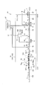
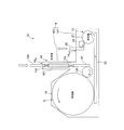
- FIG. 1 is a plan view schematically showing a gas replacement system according to a first embodiment.
- FIG. 2 is a side view schematically showing the gas replacement system shown in FIG. 1. It is a figure which shows the exit which discharges
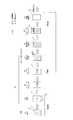
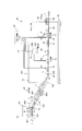
- FIG. 4 shows the processing steps for replacement, filling and sealing. It is a side view which shows typically the gas replacement system which concerns on the modification of 1st Embodiment. It is a top view which shows typically the gas replacement system which concerns on 2nd Embodiment.
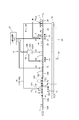
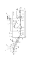
- FIG. 7 is a side view schematically showing the gas replacement system shown in FIG. 6. It is a side view which shows typically the gas replacement system which concerns on 3rd Embodiment.
- the gas replacement system 10 shown in FIG. 1 and FIG. 2 performs filling of the content liquid into the container 1 and sealing of the container 1 while conveying the container 1 (FIG. 2).
- the gas replacement system 10 includes a cleaning machine 11 (rinser), a filling machine 12 (filler), a sealing machine 13 (seamer), a chamber 14 covering the filling machine 12 and the sealing machine 13, and a replacement gas in the container 1. And a gassing system 17 to be introduced.
- the replacement gas is efficiently introduced into the container 1 when the container 1 is filled with the liquid and the container 1 after the filling is sealed.
- the gas replacement system 10 of the present embodiment covers the filling machine 12 and the sealing machine 13 by the chamber 14, and the container 1 carried into the chamber 14 in the state where liquid water is contained therein. Let it drain.
- Water is introduced into the container 1 before the container 1 is carried into the chamber 14.
- the cleaning machine 11 provided upstream of the filling machine 12 is used in this embodiment.
- the chamber 14 covers a predetermined area of the cleaning machine 11 in addition to the filling machine 12 and the sealing machine 13.
- the chamber 14 includes a continuous space from a predetermined region of the cleaning machine 11 to the filling machine 12 and the sealing machine 13.
- the space inside the chamber 14 is referred to as the inside of the chamber 14.
- a transparent window can be provided in a part of the chamber 14 so that the inside of the chamber 14 can be observed.
- the chamber 14 includes a partial chamber 141 that covers the filling machine 12 and the sealing machine 13, and a partial chamber 142 that covers a predetermined area of the cleaning machine 11.
- the insides of these partial chambers 141 and 142 are in communication with each other.
- a convenient boundary line L between the partial chamber 141 and the partial chamber 142 is indicated by a broken line, but a wall or the like need not be installed along the boundary line L.
- the washing machine 11 (rotary rinser) has a rotating body 101 and a nozzle 102 (FIG. 2) that discharges water toward the container 1 held by the rotating body 101. ing.
- the rotating body 101 is rotated by a driving device (not shown).
- the rotating body 101 has grippers 103 (FIG. 2) provided at a constant pitch on the outer peripheral portion.
- the container 1 is gripped by these grippers 103.
- the gripper 103 can change the posture of the container 1 between an upright posture and an inverted posture by rotating around a shaft portion (not shown).
- the upstream section A1 is open to the atmosphere, and the downstream section A2 from the section A1 is covered by the partial chamber 142.
- the container 1 passes through the inlet 14IN formed in the partial chamber 142 and is carried into the chamber 14.
- section A ⁇ b> 1 (hereinafter, water injection section), water is poured into the container 1 by the nozzle 102.
- section A2 hereinafter, drainage section
- the water in the container 1 is discharged outside the container 1.
- the conveyance path of the rotator 101 is divided into the water injection section A1 and the drainage section A2, but the ratio of these sections A1 and A2 is arbitrary.
- the water injection section A1 and the drainage section A2 are divided with respect to the water injection and drainage of the container 1, and the container 1 can be cleaned regardless of the classification.
- the nozzle 102 can be arrange
- the transport device of the cleaning machine 11 includes a supply conveyor 104 that supplies containers 1 supplied from a container pallet (not shown) to the cleaning machine 11, an inlet star wheel 105 that receives the containers 1 from the supply conveyor 104, and an inlet star wheel 105.
- the rotating body 101 that receives the container 1 and the star wheel 106 that receives the container 1 from the rotating body 101 and transfers it to the rotating body 18 of the filling machine 12 are configured.
- the configuration of such a transport device is merely an example, and the number and arrangement of star wheels can be determined as appropriate.
- the transfer device of the cleaning machine 11 is supported by a base 107 installed on the floor of the building.
- the wall 142A of the partial chamber 142 is installed along the diameter direction of the rotating body 101, and the semicircular region in plan view of the rotating body 101 is covered by the partial chamber 142.
- the water injection section A1 and the drainage section A2 are switched.
- the entire downstream star wheel of the two star wheels connected to each other is covered with the partial chamber 142, and the downstream star wheel is separated from the upstream star wheel.
- the water injection section A1 and the drainage section A2 may be switched at the place where the container 1 is handed over.
- the nozzle 102 (FIG. 2) ejects water supplied from a water supply source (not shown) toward the container 1 held by the gripper 103.
- the inside and outside of the container 1 are washed with water ejected from the nozzle 102.
- the nozzles 102 can be arranged on both sides of the container 1 in the vertical direction.
- the water used for washing does not need to be pure water, and may contain a bactericidal agent at a low concentration. In this embodiment, general tap water is used.
- the water that has been ejected from the nozzle 102 to clean the container 1 can be collected through a tub or the like installed below the rotating body 101. The same applies to the water discharged from the container 1.
- the nozzle 102 is disposed in at least the water injection section A1 of the water injection section A1 and the drainage section A2, and also functions as a water supply system (liquid supply system) for introducing water into the container 1.
- the nozzle 102 introduces water into the container 1 before the container 1 is carried into the drainage section A2 in the partial chamber 142 as the rotating body 101 rotates.
- the water jetted downward from the nozzle 102 is supplied into the container 1 as it is through the opening 1A of the container 1 by its own weight. It is preferable to appropriately determine the flow rate of the water ejected from the nozzle 102 so that the water ejected from the nozzle 102 can be efficiently stored in the container 1.
- water is introduced into the container 1 in the upright state (P1), and the posture of the container 1 carried into the chamber 14 is changed to the inverted state (P2) while the water is in the state. By doing so, the water in the container 1 is discharged.
- the container 1 of this embodiment is a can.
- the orientation of the opening 1A (FIG. 4) of the container 1 changes due to the change in posture. As shown in FIG. 2, in the water injection section A ⁇ b> 1, the container 1 is held in an upright state P ⁇ b> 1 with the opening 1 ⁇ / b> A facing upward by the gripper 103, and water is introduced into the container 1 by the nozzle 102.
- the container 1 When the container 1 is carried into the chamber 14 (drainage section A2) with the opening 1A facing upward, the container 1 changes to the inverted state (P2) due to the rotation of the gripper 103. Then, the water in the container 1 is discharged from the opening 1A by its own weight. That is, the gripper 103 also functions as a drainage mechanism (drainage mechanism) that drains the water in the container 1. After drainage, the container 1 is typically washed by spraying water upward from the lower side of the container 1 with the nozzle 102 while the container 1 is held in the inverted posture (P2 ′) by the gripper 103. It is possible to omit this cleaning.
- the “upright state” includes not only a state in which the opening 1A faces straight upward but also a state in which the opening 1A faces substantially upward.
- the “inverted state” includes not only a state in which the opening 1A is directed straight downward but also a state in which the opening 1A is substantially directed downward.
- the filling machine 12 includes a rotating body 18 and a filling nozzle (not shown) that fills the container 1 held by the rotating body 18 with the content liquid.
- the filling nozzle is connected to the liquid phase part 19 ⁇ / b> A in which the content liquid is stored in the filler bowl 19.
- the container 1 is held in an upright posture with the opening 1 ⁇ / b> A facing upward in pockets 20 (FIG. 2) provided at a constant pitch on the outer peripheral portion of the rotating body 18.
- the rotating body 18 is rotated by a driving device (not shown).
- the sealing machine 13 is a rotary conveying device including a lifter 21, and the container 1 is sealed by winding a lid 2 (FIG. 2) around the container 1 held by the lifter 21.
- the transfer device of the gas replacement system 10 includes the above-described rotating body 18 and lifter 21, the transfer star wheel 23 that receives the container 1 from the filling machine 12 and transfers it to the sealing machine 13, and discharges the container 1 from the sealing machine 13.
- the discharge star wheel 24 is constituted.
- the configuration of such a transport device is merely an example, and the number and arrangement of star wheels can be determined as appropriate.
- Each star wheel constituting the transport device is set to an appropriate diameter so as to satisfy a predetermined processing capacity of filling and sealing and to prevent the content liquid from spilling from the opening of the container 1 by centrifugal force.
- the transfer device of the gas replacement system 10 is supported by a common base 15 (FIG. 2), and the entire gas replacement system 10 is integrally configured.
- the base 15 is installed on the floor of the building.
- the partial chamber 141 covering the filling machine 12 and the sealing machine 13 covers the entire transport device (rotary body 18, star wheels 23, 24, lifter 21) of the gas replacement system 10 arranged well on the base 15. It is formed in a box shape and is provided on the base 15.
- the container 1 is carried into the partial chamber 142 in a state where the water introduced in the water injection section A1 of the cleaning machine 11 is accumulated. Then, the container 1 is carried from the partial chamber 142 into the partial chamber 141 by the star wheel 106 that transfers the container 1 from the cleaning machine 11 to the filling machine 12.
- the containers 1 that have been filled and sealed while being transported by the rotary body 18 and the lifter 21 in the partial chamber 141 are discharged out of the partial chamber 141 by the discharge conveyor 26.
- the discharge conveyor 26 passes through the inside and outside of the partial chamber 141 through an outlet 14OUT formed in the partial chamber 141.
- the container 1 held on the discharge conveyor 26 passes through the outlet 14OUT and is then transferred to a subsequent process such as inspection, labeling, or packing.
- the chamber 14 is provided with three openings: an inlet 14IN for receiving the container 1, an outlet 14OUT from which the container 1 exits, and a lid supply port for carrying the lid 2 into the partial chamber 141.
- the chamber 14 is sealed except for these openings.
- the opening of the chamber 14 can be closed by a flow of a liquid (for example, water) or a gas (for example, a replacement gas such as air or carbon dioxide, or a gas in the chamber 14).
- a liquid for example, water
- a gas for example, a replacement gas such as air or carbon dioxide, or a gas in the chamber 14.
- the outlet 14OUT of the chamber 14 shown in FIG. 3 is blocked by the flow of curtain-shaped water W.
- the water W is discharged downward from a plurality of discharge ports arranged at intervals in the width direction of the conveyor 25 or slits extending along the width direction.
- the width direction of the conveyor 25 coincides with the left-right direction in the figure. Since the opening of the container 1 is sealed at the outlet 14OUT, water does not flow into the container 1.
- the outlet 14OUT can also be blocked by an air flow formed in a curtain shape.
- the inlet 14IN provided in the wall 142A of the partial chamber 142 can be closed by a curtain-like air flow or can be closed by a curtain-like water W flow.
- the wall 142B that partitions the partial chamber 142 is provided with an opening 14S (not shown) through which the container 1 passes.
- the opening 14S is also preferably closed by an air flow or a water flow, like the inlet 14IN.
- the container 1 when the container 1 is filled with the content liquid in a state where air is present in the container 1, the oxygen gas contained in the air in the container 1 is dissolved in the content liquid, and the content liquid is brought into contact with the oxygen gas.
- the quality of the product may be impaired.
- the container 1 is sealed with air remaining in the head space 1H (FIG. 4), which is a space above the liquid level, because the oxygen gas contacts the content liquid.
- the head space is replaced with nitrogen gas to prevent oxidation of the non-gas beverage
- the non-gas beverage is replaced with water vapor or a mixture of nitrogen gas and water vapor when filling the can container with a non-gas beverage.
- carbon dioxide gas is used as the replacement gas.
- the gas replacement system 10 includes a tank 27 filled with liquid phase carbon dioxide, that is, liquefied carbon dioxide, as a carbon dioxide supply source.
- the carbon dioxide gas supplied through is blown into the container 1 by the gassing system 17.
- the tank 27 is connected to the gas phase portion 19B in the filler bowl 19, and the liquefied carbon dioxide gas becomes gas phase carbon dioxide gas when introduced into the gas phase portion 19B.
- the gassing system 17 (FIG. 2) includes a blowing nozzle that blows carbon dioxide gas supplied from the tank 27 and a valve that opens and closes the flow path of the blowing nozzle. Illustration of these nozzles and valves is omitted. These nozzles and valves can be provided integrally with the filling nozzle of the filling machine 12. In the case of a content liquid containing carbon dioxide gas such as beer, a counter process for pressurizing the inside of the container 1 at the time of filling, or a sniffing process for exhausting to reduce the pressure inside the container 1 when the filling nozzle is removed from the liquid is performed. . Paths and valves necessary for these processes can also be provided integrally with the filling nozzle.
- non-seal gashing and seal gashing are sequentially performed by the gashing system 17.
- the non-seal gashing is performed in a state where the opening of the container 1 is not blocked
- the seal gashing is performed in a state where the opening of the container 1 is blocked by the filling nozzle of the filling machine 12.
- the sealing device 13 carbon dioxide gas is blown between the lid 2 and the container 1, and under cover gassing is performed in which the head space 1 ⁇ / b> H in the container 1 is replaced with carbon dioxide gas.
- Non-seal gashing, seal gashing, and undercover gashing can be selectively performed by the gashing system 17 according to the liquid type.
- the configuration of the piping of the gassing system 17 can be determined as appropriate.
- the carbon dioxide gas introduced into the container 1 by the gassing system 17 leaks from the container 1 while the container 1 is transferred from the filling machine 12 to the sealing machine 13, for example. Since the leaked carbon dioxide remains in the chamber 14, the atmospheric gas in the chamber 14 has a higher concentration of carbon dioxide than the atmosphere. This concentration becomes higher as the time for which the operation of the gas replacement system 10 is continued becomes longer.
- the gas replacement system 10 of this embodiment carries the container 1 containing water into the chamber 14, and discharges the water in the container 1 in the chamber 14, so that the concentration of carbon dioxide gas is higher than the atmosphere in the chamber 14.
- the main feature is that the inside of the container 1 is replaced by the atmospheric gas inside.
- the gashing process by the gashing system 17 is performed in the chamber 14.
- the carbon dioxide gas blown at that time is discharged outside the container 1 with water during drainage. Since the inside of the container 1 is replaced with the atmospheric gas in the chamber 14 and the carbon dioxide gas concentration in the container 1 is lowered, there is no point in performing gassing. And after sealing the opening 1A of the container 1 with the filling nozzle, the container 1 cannot be drained. However, it is necessary to drain the water in the container 1 before filling the content liquid so that the content liquid is not mixed with water. As described above, the water in the container 1 carried into the chamber 14 is discharged prior to the first process (non-seal gashing in this embodiment) by the gashing system 17.
- the atmosphere gas containing carbon dioxide leaking out from the container 1 and staying in the chamber 14 is discharged before the carbon dioxide gas is introduced by the gassing system 17. 1 is introduced.
- Step S1 water supply
- step S2 drainage
- the water in the container 1 is replaced with the atmospheric gas in the chamber 14.
- Carbon dioxide (CO 2 ) contained in the atmospheric gas is introduced into the container 1 (see the arrow indicated by the broken line in FIG. 4).
- the gripper 103 returns the posture of the container 1 to the upright state P3.
- the atmospheric gas in the chamber 14 contains a gas other than carbon dioxide, for example, oxygen. However, if the operation of the gas replacement system 10 is continued, the concentration of carbon dioxide gradually increases.
- the container 1 in a full state is carried into the chamber 14 filled with the atmospheric gas whose carbon dioxide concentration is higher than the atmosphere, and the container 1 is drained in the chamber 14 so that the inside of the container 1 is discharged.
- the atmospheric gas existing in the chamber 14 is replaced.
- the container 1 that is not filled with water and is filled with the atmosphere is carried into the chamber 14, the atmosphere in the container 1 is also brought into the chamber 14 together with the container 1.
- the amount of air, that is, oxygen brought into the chamber 14 as the container 1 is carried in can be significantly reduced. A decrease in gas concentration can be suppressed. Therefore, according to this embodiment, the inside of the container 1 can be efficiently replaced by using the carbon dioxide gas in the chamber 14 while maintaining the carbon dioxide concentration in the chamber 14.
- the filling machine 12 performs the following processing.
- the counter process and sniff process which are performed when a content liquid contains a carbon dioxide gas are performed, description about it is abbreviate
- the carbon dioxide gas which is the replacement gas supplied from the tank 27, is blown into the container 1 whose opening is not blocked by the gassing system 17 into the container 1 held in the filling machine 12 (Step S3: Non-seal gas). Sing).
- the gas in the container 1 leaks from the opening of the container 1 due to the flow of the blown carbon dioxide gas, and part of the blown carbon dioxide also leaks from the opening of the container 1.
- the inside of the container 1 is rapidly replaced with carbon dioxide, and the carbon dioxide concentration in the container 1 is increased.
- step S4 seal gashing
- the vent passage is open into the chamber 14.
- the replacement of the inside of the container 1 with carbon dioxide gas further proceeds by this seal gassing, and the oxygen gas in the container 1 is more sufficiently removed.
- the content liquid is filled from the filling nozzle into the container 1 from which the oxygen gas has been removed (step S5: filling of the content liquid).
- step S5 filling of the content liquid.
- the carbon dioxide gas corresponding to the volume of the content liquid returns to the gas phase portion 19B in the filler bowl 19, but the carbon dioxide snift in the head space 1H is stored in the filling nozzle. It leaks into the chamber 14 through the gas vent. Thus, the carbon dioxide gas in the container 1 is replaced with the content liquid.
- the container 1 filled with the content liquid is transferred from the rotating body 18 of the filling machine 12 to the lifter 21 of the sealing machine 13 through the transfer star wheel 23 (step S6: transferred to the sealing machine). If the carbon dioxide gas existing in the head space 1H in the container 1 leaks from the opening of the container 1 while being transferred from the filling machine 12 to the sealing machine 13, the carbon dioxide gas in the head space 1H is discharged to the chamber 14 by the amount of the leakage. It is replaced with the atmospheric gas inside.
- FIG. 4 shows a state in which the concentration of carbon dioxide gas in the container 1 is slightly reduced due to leakage during transfer. This atmospheric gas has a higher concentration of carbon dioxide gas than air.
- the container 1 is supplied to the sealing machine 13 with the carbon dioxide concentration remaining in the container 1.
- the sealing machine 13 performs the following processing.
- the lid 2 supplied into the chamber 14 is arranged so as to face the opening of the container 1, and carbon dioxide gas is blown into the gap between the lid 2 and the container 1 by the gassing system 17 (step S 7: undercover gassing). .
- the gas in the head space 1H is blown off by the flow of the carbon dioxide gas and replaced with the carbon dioxide gas.
- the container 1 is sealed by double-tightening the container 1 lifted by the lifter 21 with the lid 2 (step S8: winding tightening). .
- the carbon dioxide gas supplied from the tank 27 and once introduced into the container 1 by the gassing system 17 leaks into the chamber 14 around the container 1.
- Examples of the carbon dioxide leaking into the chamber 14 include, for example, an excess of carbon dioxide that is blown into the container 1 and flows out of the container 1 at the time of non-seal gassing (step S3), or seal gashing (step There is exhaust from the degassing path in S4).
- the carbon dioxide gas introduced into the container 1 by the non-seal gashing and the seal gashing leaks into the chamber 14 during the sniffing process in the filling (step S5) or during the transfer (step S6).
- step S7 Much of the blown carbon dioxide leaks into the chamber 14. That is, a region having a high concentration of carbon dioxide gas is formed around the conveyance path of the container 1 in the gas replacement system 10, and the carbon dioxide gas remains in the chamber 14.
- step S2 atmospheric gas containing carbon dioxide gas leaking from the container 1 and staying in the chamber 14 is introduced into the container 1 along with drainage of the container 1 in the chamber 14 (steps). S2).
- the carbon dioxide concentration in the container 1 is higher than that in the atmosphere, so that the amount of carbon dioxide supplied from the tank 27 can be suppressed by the corresponding steps S3 and S4. That is, in step S3 and step S4, an amount of carbon dioxide that is insufficient to obtain the concentration of carbon dioxide in the predetermined container 1 may be introduced into the container 1.
- the carbon dioxide concentration in the chamber 14 is higher than the atmosphere. Since it is high, the carbon dioxide concentration is high in the head space 1H.
- the amount of carbon dioxide used by the gassing system 17 can be reduced by the amount of the high carbon dioxide concentration in the undercover gassing step S7.
- the present embodiment almost all of the carbon dioxide leaked out of the container 1 is retained in the chamber 14, and after the container 1 carried into the chamber 14 is drained in a state where water is contained, the gassing system is discharged. 17 is performed. Therefore, according to this embodiment, while greatly reducing the amount of carbon dioxide gas supplied from the tank 27, the inside of the container 1 is efficiently replaced to reduce the oxygen gas concentration in the space in the container 1 and the content liquid. It can be sufficiently reduced. Reducing the amount of carbon dioxide used can reduce manufacturing costs and contribute to safety in the work environment and protection of the natural environment.
- the inside of the chamber 14 becomes a positive pressure with respect to the outside of the chamber 14, which is the atmospheric pressure. Invasion of foreign substances such as insects and insects can be avoided. Therefore, since it is not necessary to prepare a room with particularly thorough hygiene management in order to install the gas replacement system 10, it is possible to suppress capital investment and to have a degree of freedom in changing the device configuration of the production line. high.
- the chamber 14 is sufficient if it covers the conveyance path of the container 1 and its surroundings from the discharge of the water in the container 1 through the processing by the gassing system 17 until the container 1 is sealed.
- the area where the water in the container 1 is discharged by the gripper 103 in the cleaning machine 11 is included in the area covered by the chamber 14.
- a gripper 103 as a drainage mechanism may be provided in the rotating body of the filling machine 12. In that case, it is sufficient if the chamber 14 covers the filling machine 12 and the sealing machine 13.
- the inside of the chamber 14 can be partitioned by a wall, and a gas having a high carbon dioxide gas concentration can be supplied to the vicinity of the position where the water in the container 1 is discharged due to a pressure difference between both sides of the wall.
- the wall can be installed, for example, at the position of the boundary line L shown in FIG.
- the pressure is relatively high due to the leakage of carbon dioxide gas from the inside of the container 1, and the pressure on the upstream side of the wall is relatively low, so that through an appropriate path communicating on both sides of the wall, A gas having a high carbon dioxide gas concentration can be efficiently fed into the container 1 before gassing.
- the gas replacement system 30 includes a water supply system 50 (FIG. 7), a cleaning machine 40, a filling machine 12, a sealing machine 13, a chamber 14, and a gassing system 17.
- the water supply system 50 includes a water supply source 51 and a water supply nozzle 52 that pours water supplied from the water supply source 51 into the container 1. Transfer of the container 1 from the filling machine 12 to the sealing machine 13 is performed by a transfer conveyor 33.
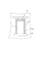
- the washing machine 40 includes a frame 401 (container conveyance path) made of a plurality of metal guide bars (round bars) and a nozzle 402 (FIG. 7) for ejecting water. Water is showered from the nozzle 402 while rolling 1 by its own weight.
- the guide rods constituting the frame 401 extend so as to gradually descend from above to below.
- the frame 401 has a twist section TW in which the guide bar is twisted.
- position of the container 1 is reversed by self-propelling the twist area TW.
- the twist sections TW are respectively arranged on the upstream side and the downstream side of the frame 401.
- a region from the upstream twist section TW to the downstream twist section TW is covered with a cleaning chamber 403.
- the inside of the cleaning chamber 403 communicates with the inside of the partial chamber 141 that covers the filling machine 12 and the sealing machine 13.
- the cleaning chamber 403 and the partial chamber 141 constitute a chamber 14 that includes a continuous space.
- an inlet 14IN for receiving the container 1 in the chamber 14 is provided in the cleaning chamber 403.
- the chamber 14 can be divided into appropriate portions.
- the chamber 14 can also be configured.
- the container 1 is supplied in a full state by the water supply nozzle 52 of the water supply system 50 while being conveyed in the upright state P1 by the supply conveyor 104 (step S1: water supply). Thereafter, the container 1 is carried into the chamber 14 (into the cleaning chamber 403), and in the inverted state P2 in the upstream twist section TW. Water is discharged from the inside of the container 1 in the inverted state P2 (step S2: drainage). That is, the upstream twist section TW functions as a drainage mechanism.
- the container 1 in a sideways posture without being inverted. As the water is discharged from the container 1, the inside of the container 1 is replaced with the atmospheric gas in the chamber 14 containing carbon dioxide gas.
- the container 1 is washed by the water ejected from the nozzle 402 while rolling down in the frame 401 in an inverted state. At this time, even if the washing water enters the container 1, it is immediately discharged by its own weight.
- the nozzles 402 may be arranged on both the opening 1A side and the bottom side of the container 1.
- the containers 1 are returned to the upright state P3 in the downstream twist section TW, and then delivered to the conveyor 25 that conveys the containers 1 toward the filling machine 12. Thereafter, processing similar to the processing (S3 to S8) of the first embodiment (FIG. 4) is performed.
- the second embodiment as in the first embodiment, almost all of the carbon dioxide leaked out of the container 1 is kept in the chamber 14 and the container carried into the chamber 14 in a state where water is contained. After draining 1, processing by the gassing system 17 is performed. Therefore, according to the second embodiment, while the amount of carbon dioxide used is greatly reduced, the inside of the container 1 can be efficiently replaced to sufficiently reduce the oxygen gas concentration in the space in the container 1 and the content liquid. Can do.
- Introducing the atmospheric gas in the chamber 14 by supplying water into the container 1 and discharging the water in the container 1 is performed on the assumption that the carbon dioxide concentration in the chamber 14 is higher than the atmosphere. Is called. Therefore, when the inside of the chamber 14 is filled with the atmosphere at the beginning of the operation of the filling machine 12 and the sealing machine 13, it waits for the inside of the chamber 14 to reach a predetermined carbon dioxide concentration, and the water supply system 50 It is preferable to start water supply into the container 1. Further, at the start of operation, carbon dioxide gas may be introduced into the chamber 14 in advance so that the carbon dioxide gas concentration is higher in the chamber 14 than in the atmosphere, and water supply into the container 1 may be performed from the beginning of operation.
- the container 1 is cleaned by supplying water into the container 1 and draining from the container 1, and the cleaning process of showering from the nozzle 402 to the container 1 rolling in the frame 401 can be omitted.
- the cleaning process of showering from the nozzle 402 to the container 1 rolling in the frame 401 can be omitted.
- the roll-through type washing machine as in the second embodiment is used not only for washing the container 1 but also for supplying water into the container 1 as in the washing machine 11 of the first embodiment.
- the water supply system 50 for pouring water can also be abolished.
- the twist section TW and the nozzle 402 are arranged at appropriate positions so that water can be supplied from the nozzle 402 into the upright container 1. Then, the place where water is supplied into the container 1 is opened to the atmosphere without being covered by the chamber 14, and the container 1 in a state where water is contained is carried into the chamber 14, and then drained in the twist section TW in the chamber 14. To be. Even if the container 1 is not full when it is carried into the chamber 14, the amount of carbon dioxide gas used is replaced with the gas containing carbon dioxide in the cleaning chamber 403 by the amount drained from the container 1. It can contribute to reduction.
- water is introduced between the containers 1 and 1 at the place where the container 1 is carried into the chamber 14.
- the inlet 14IN of the chamber 14 corresponds to a place where the container 1 is carried into the chamber 14.
- water is discharged in the form of a curtain from the water supply nozzle 53 provided in the water supply system 50 at the position of the inlet 14IN through which the supply conveyor 104 passes.
- a preferred configuration of the water supply nozzle 53 will be described.
- step S1 water supply
- the air in the container 1 is replaced with water
- the air between the containers 1 and 1 is also replaced with water.
- 1 also introduces water so that the amount of air entering the chamber 14 can be further suppressed.
- step S2 Drainage
- the water introduced between the containers 1 and 1 flows out from between the containers 1 and 1 immediately after the container 1 is carried into the chamber 14 because there is no bank or the like for retaining the water there. Thereafter, processing similar to the processing (S3 to S8) of the first embodiment (FIG. 4) is performed.
- the water flow 53F at the inlet 14IN of the chamber 14 replaces not only the container 1 but also the gap between the containers 1 and 1 with water when the container 1 is carried into the chamber 14. Moreover, the inlet 14IN of the chamber 14 is blocked by the water flow 53F. Therefore, air can be prevented from entering the chamber 14 as the container 1 is carried into the chamber 14, and atmospheric gas in the chamber 14 can be prevented from leaking out of the chamber 14 through the inlet 14IN. In other words, the degree of sealing in the chamber 14 is increased, the atmospheric gas in the chamber 14, particularly carbon dioxide can be used without waste, and the inside of the chamber 14 is reliably maintained at a positive pressure to avoid intrusion of foreign substances and the like. Can do.
- the water supply nozzle 53 similarly to the water supply nozzle 52 of the second embodiment (FIG. 7), it is possible to provide only an upper nozzle that discharges water from above to the container 1 rather than the container 1, but the upper nozzle, By combining the side nozzle that blows out from the direction orthogonal to the transport direction, water can be introduced more reliably between the containers 1 and 1.
- a set of nozzles for discharging water in the form of a curtain may be added to the position of the inlet 14IN of the chamber 14 and arranged at a position upstream from the position.
- the water introduced between the containers 1 and 1 flows out between the containers 1 and 1 without being held there, in order not to bring the air between the containers 1 and 1 into the chamber 14, It is necessary to introduce water between the containers 1 and 1 by the nozzle at the position of the inlet 14IN. Water can be introduced only between the containers 1 and 1 at the position of the inlet 14IN, and water can be introduced only into the container 1 at a position upstream thereof.
- the water flow 53F can also be formed by the water supply nozzle 53 at the position of the inlet 14IN of the partial chamber 142 that covers a predetermined area of the cleaning machine 11 in the first embodiment. Thereby, the same effect as that of the third embodiment can be obtained.
- carbon dioxide gas is introduced into the container 1 by the gassing system 17 in the chamber 14.
- processing by the gassing system 17 is performed. That is not essential. That is, the container 1 containing water is carried into the chamber 14 and the water is discharged from the container 1 in the chamber 14, thereby only efficiently maintaining the carbon dioxide gas concentration in the chamber 14. It is possible to replace the inside of the container 1 using the carbon dioxide gas inside. Therefore, a configuration in which the gassing system 17 is removed from the gas replacement system according to the first to third embodiments is also included in the present invention.
- the filling machine 12 that fills the container 1 with the content liquid, the sealing machine 13 that seals the container 1 transferred from the filling machine 12, the filling machine 12 and the sealing machine 13 are covered, and the replacement gas is
- a gas replacement system including an existing chamber 14 and a drainage mechanism that discharges the water in the container 1 that has been carried into the chamber 14 in a state of containing water to the outside of the container 1 in the chamber 14.
- the inside of the chamber 14 is made an atmosphere in which the N 2 gas concentration is higher than the atmosphere, and the container 1 containing water is carried into the chamber 14 and drained in the chamber 14.
- the atmosphere 1 in the chamber 14 containing N 2 gas is replaced with the inside of the container 1, and thereafter, the content liquid can be filled in the container 1 without performing a gassing process.
- the container in the present invention is not limited to a can body, and may be a PET bottle or a glass bottle.
- the containers are sealed in a way that suits each.
- Examples of the lid for sealing the container, that is, the packaging material for sealing the container 1, include a cap for the bottle and a film-like material for sealing the opening of the container body.
- the liquid that is a medium for replacing the inside of the container 1 with the atmospheric gas in the chamber 14 as it is discharged from the inside of the container 14 in the chamber 14 is typified by water.
- the container 1 carried into the chamber 14 in the state where the liquid is contained is After being drained in 14, it can be configured appropriately as long as it is gassed.
- Such a system does not necessarily include a cleaning device that cleans the container 1, and even this method does not necessarily require a cleaning process of the container 1.
- the drainage mechanism and the liquid supply system according to the present invention can be easily realized by using the configurations of the washing machines 11, 40 and the like provided as the upstream process of the filling machine 12, there are few elements to be added. In addition, the cost of the gas replacement system can be reduced.
- the grip rinser is provided with a conveyance path for conveying the container 1 by sandwiching the container 1 from both sides with a rubber belt.
- the conveyance path there are first and second sections in which the posture of the container is reversed while the container is sandwiched between rubber belts wound around a rotating body that rotates about a horizontal axis.
- washing water can be poured from a nozzle into a container conveyed in an upright state, and the water in the container can be discharged as the container is reversed in the first section.
- a washing machine used for a beer bottle or the like cleans a container by putting bottles in a plurality of rows of bottle gauges and immersing the bottle gauges together in a cleaning solution. After cleaning, the cleaning liquid in the bottle is discharged by inverting the bottle by rotating the bottle gauge. The bottle is then returned to the upright state and discharged for the filling process.
- an appropriate washing machine can be used depending on the type of container.
- the container 1 can be cleaned by water supply (water injection) and drainage into the container 1, the container 1 may be cleaned at an appropriate timing as necessary.
- the container 1 can be drained while being washed by the washing machine 40, and water is supplied into the container 1 after the container 1 is washed. Then, it can be drained.
- cleaning water remains in the container 1, it is sufficient to supply water to the remaining space in the container 1. That is, water is stored in the container 1 from the cleaning process to the water supply process.
- the container 1 can be drained after water supply into the container 1 and then the container 1 can be washed.
- the cleaning of the container 1 does not have to be performed in the chamber 14.
- “To supply water into the container before being carried in” includes supplying water at the same time when the container 1 is carried into the chamber 14 as in the third embodiment.
- the container 1 it is not essential to change the posture of the container 1 in order to supply and drain water.
- the water in the container 1 conveyed in an upright state by the conveyor can be discharged out of the container 1 by sucking out the water with a nozzle.
- position of the container 1 is an upright state at the time of water supply.
- the container 1 is carried into the chamber 14 while the opening 1A of the container 1 into which water has been introduced in an inverted state is closed with an appropriate member, and the water in the container 1 is drained by opening the opening 1A in the chamber 14. It is allowed to be discharged.
- the configuration described in the above embodiment can be selected or changed to another configuration as appropriate.
- the content liquid filled in the container 1 are not limited to beer and beer-based beverages, and can include all alcoholic beverages and beverages such as sake, western liquor, coffee beverages, fruit juice beverages, and tea beverages.
- the present invention can be applied to such alcoholic beverages and beverages that dislike oxidation.
- the liquid with which a container is filled is not limited to beverages, and may be any liquid that requires quality maintenance by using a replacement gas.
Landscapes
- Chemical & Material Sciences (AREA)
- Dispersion Chemistry (AREA)
- Engineering & Computer Science (AREA)
- Mechanical Engineering (AREA)
- Filling Of Jars Or Cans And Processes For Cleaning And Sealing Jars (AREA)
- Vacuum Packaging (AREA)
Priority Applications (3)
| Application Number | Priority Date | Filing Date | Title |
|---|---|---|---|
| CN201680043552.8A CN107922067B (zh) | 2015-08-24 | 2016-08-22 | 气体置换系统及气体置换方法 |
| US15/746,862 US11180357B2 (en) | 2015-08-24 | 2016-08-22 | Gas replacement system and gas replacement method |
| EP16838804.9A EP3342720B1 (en) | 2015-08-24 | 2016-08-22 | Gas replacement system and gas replacement method |
Applications Claiming Priority (2)
| Application Number | Priority Date | Filing Date | Title |
|---|---|---|---|
| JP2015165232A JP6534315B2 (ja) | 2015-08-24 | 2015-08-24 | ガス置換システムおよびガス置換方法 |
| JP2015-165232 | 2015-08-24 |
Publications (1)
| Publication Number | Publication Date |
|---|---|
| WO2017033454A1 true WO2017033454A1 (ja) | 2017-03-02 |
Family
ID=58099715
Family Applications (1)
| Application Number | Title | Priority Date | Filing Date |
|---|---|---|---|
| PCT/JP2016/003809 Ceased WO2017033454A1 (ja) | 2015-08-24 | 2016-08-22 | ガス置換システムおよびガス置換方法 |
Country Status (6)
| Country | Link |
|---|---|
| US (1) | US11180357B2 (https=) |
| EP (1) | EP3342720B1 (https=) |
| JP (1) | JP6534315B2 (https=) |
| CN (1) | CN107922067B (https=) |
| TW (1) | TWI636921B (https=) |
| WO (1) | WO2017033454A1 (https=) |
Cited By (3)
| Publication number | Priority date | Publication date | Assignee | Title |
|---|---|---|---|---|
| CN108467000A (zh) * | 2018-03-26 | 2018-08-31 | 燕京啤酒(玉林)有限公司 | 一种使用氮气代替二氧化碳进行啤酒灌装的方法 |
| EP3686114A1 (en) * | 2017-12-08 | 2020-07-29 | Plf International Limited | Vacuum extraction and sealing of containers |
| CN115246624A (zh) * | 2021-04-27 | 2022-10-28 | 河北燕京啤酒有限公司 | 一种啤酒灌装方法及啤酒灌装系统 |
Families Citing this family (9)
| Publication number | Priority date | Publication date | Assignee | Title |
|---|---|---|---|---|
| SE539899C2 (en) | 2016-04-15 | 2018-01-02 | A & R Carton Lund Ab | Paperboard packaging container with a lid and a method for producing such a container |
| SE543099C2 (en) | 2018-05-23 | 2020-10-06 | A & R Carton Lund Ab | Flexible membrane with valve |
| SE542898C2 (en) | 2018-08-31 | 2020-08-18 | Å&R Carton Lund Ab | A composite container with separable top, a body blank, and a method of separating a top end portion from a main body of the container |
| SE544358C2 (en) | 2019-07-02 | 2022-04-19 | A & R Carton Lund Ab | Method of producing a packaging container and a packaging container |
| JP6878517B2 (ja) * | 2019-08-02 | 2021-05-26 | メロディアン株式会社 | 食用油入り小分け容器の製造方法 |
| SE544445C2 (en) | 2019-12-12 | 2022-05-31 | Ar Packaging Systems Ab | Method of producing a packaging container, a packaging container and a curling tool |
| US12337357B2 (en) * | 2020-03-30 | 2025-06-24 | Chemtreat, Inc. | Methods and systems for online cleaning of beverage fillers |
| DE102020130654A1 (de) * | 2020-11-19 | 2022-05-19 | Multivac Sepp Haggenmüller Se & Co. Kg | Verpackungsvorrichtung |
| SE546556C2 (en) | 2022-05-25 | 2024-12-03 | Gpi Systems Ab | Method of producing packaging container comprising a valve |
Citations (3)
| Publication number | Priority date | Publication date | Assignee | Title |
|---|---|---|---|---|
| JPS5050187A (https=) * | 1973-08-24 | 1975-05-06 | ||
| US20120297732A1 (en) * | 2010-09-20 | 2012-11-29 | Bonduelle | Method for packaging a liquid product |
| US20120308699A1 (en) * | 2010-09-20 | 2012-12-06 | Bonduelle | Method for packaging non-liquid food products, in particular those sensitive to oxygen, in a container with a low oxygen content |
Family Cites Families (17)
| Publication number | Priority date | Publication date | Assignee | Title |
|---|---|---|---|---|
| US3899862A (en) * | 1971-04-06 | 1975-08-19 | Lever Brothers Ltd | Sterilization of containers |
| US4014158A (en) * | 1973-08-24 | 1977-03-29 | Ab Ziristor | Apparatus for filling and sealing preformed packaging containers under aseptic conditions |
| FR2578817B2 (fr) * | 1984-03-22 | 1987-10-09 | Larroche Michel | Couvercle de recipient destine a contenir un produit alimentaire aqueux, recipient pourvu de ce couvercle et procede de fermeture etanche dudit recipient |
| JPH05330515A (ja) * | 1992-05-25 | 1993-12-14 | Toppan Printing Co Ltd | 充填密封容器ヘッドスペースのガス置換方法 |
| JPH06179428A (ja) * | 1992-12-08 | 1994-06-28 | Shikoku Kakoki Co Ltd | 内容物充填金属缶の製造装置 |
| JPH09323793A (ja) | 1996-06-05 | 1997-12-16 | Mitsubishi Heavy Ind Ltd | 密閉室への物品搬出入装置 |
| JP3468999B2 (ja) | 1996-08-16 | 2003-11-25 | 三菱重工業株式会社 | 密閉室の容器搬送装置 |
| ATE242975T1 (de) * | 1999-03-08 | 2003-07-15 | Nestle Sa | Ein behälter und ein trinkfertiges getränk enthaltende anordnung |
| US20020085971A1 (en) * | 2001-01-03 | 2002-07-04 | Raniwala Subodh K. | Bottle sterilizing system and method |
| DE602005022872D1 (de) * | 2004-07-09 | 2010-09-23 | Nestec Sa | Gerät mit druckgasversorgung zur getränkezubereitung |
| US20070056251A1 (en) * | 2005-01-05 | 2007-03-15 | Ruppman Kurt H Sr | Method and Apparatus for Flushing a Container with an Inert Gas |
| US20080187632A1 (en) * | 2005-05-04 | 2008-08-07 | Matthew Eric Smith | Beverage Foaming Devices |
| KR101294645B1 (ko) * | 2006-06-09 | 2013-08-09 | 도요세이칸 그룹 홀딩스 가부시키가이샤 | 용기 살균·세정 방법 및 장치 |
| DE102007029567A1 (de) * | 2007-06-26 | 2009-01-02 | Krones Ag | Sterilisation mit β-Strahlung |
| WO2011151902A1 (ja) * | 2010-06-02 | 2011-12-08 | 東洋製罐株式会社 | 容器のガス置換方法及び装置 |
| JP5626513B2 (ja) * | 2010-06-16 | 2014-11-19 | 東洋製罐株式会社 | 容器の殺菌、洗浄方法 |
| JP2014073855A (ja) * | 2012-10-04 | 2014-04-24 | Mitsubishi Heavy Industries Food & Packaging Machinery Co Ltd | 飲料充填方法 |
-
2015
- 2015-08-24 JP JP2015165232A patent/JP6534315B2/ja active Active
-
2016
- 2016-08-22 WO PCT/JP2016/003809 patent/WO2017033454A1/ja not_active Ceased
- 2016-08-22 CN CN201680043552.8A patent/CN107922067B/zh active Active
- 2016-08-22 EP EP16838804.9A patent/EP3342720B1/en active Active
- 2016-08-22 US US15/746,862 patent/US11180357B2/en active Active
- 2016-08-23 TW TW105126959A patent/TWI636921B/zh active
Patent Citations (3)
| Publication number | Priority date | Publication date | Assignee | Title |
|---|---|---|---|---|
| JPS5050187A (https=) * | 1973-08-24 | 1975-05-06 | ||
| US20120297732A1 (en) * | 2010-09-20 | 2012-11-29 | Bonduelle | Method for packaging a liquid product |
| US20120308699A1 (en) * | 2010-09-20 | 2012-12-06 | Bonduelle | Method for packaging non-liquid food products, in particular those sensitive to oxygen, in a container with a low oxygen content |
Non-Patent Citations (1)
| Title |
|---|
| See also references of EP3342720A4 * |
Cited By (9)
| Publication number | Priority date | Publication date | Assignee | Title |
|---|---|---|---|---|
| EP3686114A1 (en) * | 2017-12-08 | 2020-07-29 | Plf International Limited | Vacuum extraction and sealing of containers |
| CN111572858A (zh) * | 2017-12-08 | 2020-08-25 | Plf国际有限公司 | 容器的真空提取和密封 |
| US11117696B2 (en) | 2017-12-08 | 2021-09-14 | Plf International Limited | Vacuum extraction and sealing of containers |
| US11661221B2 (en) | 2017-12-08 | 2023-05-30 | Plf International Limited | Vacuum extraction and sealing of containers |
| US12139285B2 (en) | 2017-12-08 | 2024-11-12 | Plf International Limited | Vacuum extraction and sealing of containers |
| EP4541759A3 (en) * | 2017-12-08 | 2025-07-09 | Plf International Limited | Vacuum extraction and sealing of containers |
| CN108467000A (zh) * | 2018-03-26 | 2018-08-31 | 燕京啤酒(玉林)有限公司 | 一种使用氮气代替二氧化碳进行啤酒灌装的方法 |
| CN108467000B (zh) * | 2018-03-26 | 2020-08-04 | 燕京啤酒(玉林)有限公司 | 一种使用氮气代替二氧化碳进行啤酒灌装的方法 |
| CN115246624A (zh) * | 2021-04-27 | 2022-10-28 | 河北燕京啤酒有限公司 | 一种啤酒灌装方法及啤酒灌装系统 |
Also Published As
| Publication number | Publication date |
|---|---|
| CN107922067A (zh) | 2018-04-17 |
| US20200079635A1 (en) | 2020-03-12 |
| TW201711921A (zh) | 2017-04-01 |
| US11180357B2 (en) | 2021-11-23 |
| TWI636921B (zh) | 2018-10-01 |
| EP3342720A1 (en) | 2018-07-04 |
| EP3342720A4 (en) | 2019-04-10 |
| EP3342720B1 (en) | 2025-04-30 |
| CN107922067B (zh) | 2020-03-13 |
| JP6534315B2 (ja) | 2019-06-26 |
| JP2017043371A (ja) | 2017-03-02 |
Similar Documents
| Publication | Publication Date | Title |
|---|---|---|
| WO2017033454A1 (ja) | ガス置換システムおよびガス置換方法 | |
| JP6266570B2 (ja) | 充填密封装置および充填密封方法 | |
| JP6075535B2 (ja) | 充填密封方法及び装置 | |
| JP6044652B2 (ja) | 包装体の製造方法及び装置 | |
| RU2342314C2 (ru) | Машина для обработки емкости | |
| CN116040561B (zh) | 碳酸饮料无菌填充系统、饮料填充系统及cip处理方法 | |
| US20020083682A1 (en) | Aseptic bottle filling system | |
| KR101474893B1 (ko) | 용기의 살균, 세정 방법 | |
| EP3517451B1 (en) | Aseptic filling machine, and aseptic filling method | |
| US20230356271A1 (en) | Container washing facility | |
| JP5998539B2 (ja) | 洗浄充填装置 | |
| JP5239553B2 (ja) | 充填装置の洗浄方法および充填装置 | |
| CN114787040A (zh) | 盖体杀菌装置以及内容物填充系统 | |
| JP2014073855A (ja) | 飲料充填方法 | |
| JP4366637B2 (ja) | 容器の洗浄・水切り方法および装置 | |
| JP6395063B2 (ja) | キャップ殺菌装置、内容物充填システムおよびキャップ殺菌方法 | |
| WO2019102816A1 (ja) | 容器処理装置および容器処理方法 | |
| US8365780B2 (en) | Method for filling containers | |
| JP6292261B2 (ja) | キャップ殺菌装置、内容物充填システムおよびキャップ殺菌方法 | |
| JP2005313976A (ja) | 容器ヘッドスペースのガス置換装置 | |
| ITVR990098A1 (it) | Gruppo di sanificazione per macchina tappatrice in continuo di bottiglie mediante turaccioli e metodo di sanificazione in particolare per ta |
Legal Events
| Date | Code | Title | Description |
|---|---|---|---|
| 121 | Ep: the epo has been informed by wipo that ep was designated in this application |
Ref document number: 16838804 Country of ref document: EP Kind code of ref document: A1 |
|
| NENP | Non-entry into the national phase |
Ref country code: DE |
|
| WWG | Wipo information: grant in national office |
Ref document number: 2016838804 Country of ref document: EP |