WO2017033354A1 - 車両の制御装置 - Google Patents
車両の制御装置 Download PDFInfo
- Publication number
- WO2017033354A1 WO2017033354A1 PCT/JP2016/002580 JP2016002580W WO2017033354A1 WO 2017033354 A1 WO2017033354 A1 WO 2017033354A1 JP 2016002580 W JP2016002580 W JP 2016002580W WO 2017033354 A1 WO2017033354 A1 WO 2017033354A1
- Authority
- WO
- WIPO (PCT)
- Prior art keywords
- engine
- voltage battery
- battery
- power
- vehicle
- Prior art date
- Legal status (The legal status is an assumption and is not a legal conclusion. Google has not performed a legal analysis and makes no representation as to the accuracy of the status listed.)
- Ceased
Links
Images



Classifications
-
- F—MECHANICAL ENGINEERING; LIGHTING; HEATING; WEAPONS; BLASTING
- F02—COMBUSTION ENGINES; HOT-GAS OR COMBUSTION-PRODUCT ENGINE PLANTS
- F02N—STARTING OF COMBUSTION ENGINES; STARTING AIDS FOR SUCH ENGINES, NOT OTHERWISE PROVIDED FOR
- F02N11/00—Starting of engines by means of electric motors
- F02N11/08—Circuits specially adapted for starting of engines
- F02N11/0814—Circuits specially adapted for starting of engines comprising means for controlling automatic idle-start-stop
- F02N11/0844—Circuits specially adapted for starting of engines comprising means for controlling automatic idle-start-stop with means for restarting the engine directly after an engine stop request, e.g. caused by change of driver mind
-
- B—PERFORMING OPERATIONS; TRANSPORTING
- B60—VEHICLES IN GENERAL
- B60K—ARRANGEMENT OR MOUNTING OF PROPULSION UNITS OR OF TRANSMISSIONS IN VEHICLES; ARRANGEMENT OR MOUNTING OF PLURAL DIVERSE PRIME-MOVERS IN VEHICLES; AUXILIARY DRIVES FOR VEHICLES; INSTRUMENTATION OR DASHBOARDS FOR VEHICLES; ARRANGEMENTS IN CONNECTION WITH COOLING, AIR INTAKE, GAS EXHAUST OR FUEL SUPPLY OF PROPULSION UNITS IN VEHICLES
- B60K6/00—Arrangement or mounting of plural diverse prime-movers for mutual or common propulsion, e.g. hybrid propulsion systems comprising electric motors and internal combustion engines
- B60K6/20—Arrangement or mounting of plural diverse prime-movers for mutual or common propulsion, e.g. hybrid propulsion systems comprising electric motors and internal combustion engines the prime-movers consisting of electric motors and internal combustion engines, e.g. HEVs
- B60K6/22—Arrangement or mounting of plural diverse prime-movers for mutual or common propulsion, e.g. hybrid propulsion systems comprising electric motors and internal combustion engines the prime-movers consisting of electric motors and internal combustion engines, e.g. HEVs characterised by apparatus, components or means specially adapted for HEVs
- B60K6/28—Arrangement or mounting of plural diverse prime-movers for mutual or common propulsion, e.g. hybrid propulsion systems comprising electric motors and internal combustion engines the prime-movers consisting of electric motors and internal combustion engines, e.g. HEVs characterised by apparatus, components or means specially adapted for HEVs characterised by the electric energy storing means, e.g. batteries or capacitors
-
- B—PERFORMING OPERATIONS; TRANSPORTING
- B60—VEHICLES IN GENERAL
- B60K—ARRANGEMENT OR MOUNTING OF PROPULSION UNITS OR OF TRANSMISSIONS IN VEHICLES; ARRANGEMENT OR MOUNTING OF PLURAL DIVERSE PRIME-MOVERS IN VEHICLES; AUXILIARY DRIVES FOR VEHICLES; INSTRUMENTATION OR DASHBOARDS FOR VEHICLES; ARRANGEMENTS IN CONNECTION WITH COOLING, AIR INTAKE, GAS EXHAUST OR FUEL SUPPLY OF PROPULSION UNITS IN VEHICLES
- B60K6/00—Arrangement or mounting of plural diverse prime-movers for mutual or common propulsion, e.g. hybrid propulsion systems comprising electric motors and internal combustion engines
- B60K6/20—Arrangement or mounting of plural diverse prime-movers for mutual or common propulsion, e.g. hybrid propulsion systems comprising electric motors and internal combustion engines the prime-movers consisting of electric motors and internal combustion engines, e.g. HEVs
- B60K6/42—Arrangement or mounting of plural diverse prime-movers for mutual or common propulsion, e.g. hybrid propulsion systems comprising electric motors and internal combustion engines the prime-movers consisting of electric motors and internal combustion engines, e.g. HEVs characterised by the architecture of the hybrid electric vehicle
- B60K6/44—Series-parallel type
- B60K6/442—Series-parallel switching type
-
- B—PERFORMING OPERATIONS; TRANSPORTING
- B60—VEHICLES IN GENERAL
- B60K—ARRANGEMENT OR MOUNTING OF PROPULSION UNITS OR OF TRANSMISSIONS IN VEHICLES; ARRANGEMENT OR MOUNTING OF PLURAL DIVERSE PRIME-MOVERS IN VEHICLES; AUXILIARY DRIVES FOR VEHICLES; INSTRUMENTATION OR DASHBOARDS FOR VEHICLES; ARRANGEMENTS IN CONNECTION WITH COOLING, AIR INTAKE, GAS EXHAUST OR FUEL SUPPLY OF PROPULSION UNITS IN VEHICLES
- B60K6/00—Arrangement or mounting of plural diverse prime-movers for mutual or common propulsion, e.g. hybrid propulsion systems comprising electric motors and internal combustion engines
- B60K6/20—Arrangement or mounting of plural diverse prime-movers for mutual or common propulsion, e.g. hybrid propulsion systems comprising electric motors and internal combustion engines the prime-movers consisting of electric motors and internal combustion engines, e.g. HEVs
- B60K6/42—Arrangement or mounting of plural diverse prime-movers for mutual or common propulsion, e.g. hybrid propulsion systems comprising electric motors and internal combustion engines the prime-movers consisting of electric motors and internal combustion engines, e.g. HEVs characterised by the architecture of the hybrid electric vehicle
- B60K6/48—Parallel type
- B60K6/485—Motor-assist type
-
- B—PERFORMING OPERATIONS; TRANSPORTING
- B60—VEHICLES IN GENERAL
- B60K—ARRANGEMENT OR MOUNTING OF PROPULSION UNITS OR OF TRANSMISSIONS IN VEHICLES; ARRANGEMENT OR MOUNTING OF PLURAL DIVERSE PRIME-MOVERS IN VEHICLES; AUXILIARY DRIVES FOR VEHICLES; INSTRUMENTATION OR DASHBOARDS FOR VEHICLES; ARRANGEMENTS IN CONNECTION WITH COOLING, AIR INTAKE, GAS EXHAUST OR FUEL SUPPLY OF PROPULSION UNITS IN VEHICLES
- B60K6/00—Arrangement or mounting of plural diverse prime-movers for mutual or common propulsion, e.g. hybrid propulsion systems comprising electric motors and internal combustion engines
- B60K6/20—Arrangement or mounting of plural diverse prime-movers for mutual or common propulsion, e.g. hybrid propulsion systems comprising electric motors and internal combustion engines the prime-movers consisting of electric motors and internal combustion engines, e.g. HEVs
- B60K6/50—Architecture of the driveline characterised by arrangement or kind of transmission units
- B60K6/54—Transmission for changing ratio
- B60K6/543—Transmission for changing ratio the transmission being a continuously variable transmission
-
- B—PERFORMING OPERATIONS; TRANSPORTING
- B60—VEHICLES IN GENERAL
- B60K—ARRANGEMENT OR MOUNTING OF PROPULSION UNITS OR OF TRANSMISSIONS IN VEHICLES; ARRANGEMENT OR MOUNTING OF PLURAL DIVERSE PRIME-MOVERS IN VEHICLES; AUXILIARY DRIVES FOR VEHICLES; INSTRUMENTATION OR DASHBOARDS FOR VEHICLES; ARRANGEMENTS IN CONNECTION WITH COOLING, AIR INTAKE, GAS EXHAUST OR FUEL SUPPLY OF PROPULSION UNITS IN VEHICLES
- B60K6/00—Arrangement or mounting of plural diverse prime-movers for mutual or common propulsion, e.g. hybrid propulsion systems comprising electric motors and internal combustion engines
- B60K6/20—Arrangement or mounting of plural diverse prime-movers for mutual or common propulsion, e.g. hybrid propulsion systems comprising electric motors and internal combustion engines the prime-movers consisting of electric motors and internal combustion engines, e.g. HEVs
- B60K6/50—Architecture of the driveline characterised by arrangement or kind of transmission units
- B60K6/54—Transmission for changing ratio
- B60K6/547—Transmission for changing ratio the transmission being a stepped gearing
-
- B—PERFORMING OPERATIONS; TRANSPORTING
- B60—VEHICLES IN GENERAL
- B60W—CONJOINT CONTROL OF VEHICLE SUB-UNITS OF DIFFERENT TYPE OR DIFFERENT FUNCTION; CONTROL SYSTEMS SPECIALLY ADAPTED FOR HYBRID VEHICLES; ROAD VEHICLE DRIVE CONTROL SYSTEMS FOR PURPOSES NOT RELATED TO THE CONTROL OF A PARTICULAR SUB-UNIT
- B60W10/00—Conjoint control of vehicle sub-units of different type or different function
-
- B—PERFORMING OPERATIONS; TRANSPORTING
- B60—VEHICLES IN GENERAL
- B60W—CONJOINT CONTROL OF VEHICLE SUB-UNITS OF DIFFERENT TYPE OR DIFFERENT FUNCTION; CONTROL SYSTEMS SPECIALLY ADAPTED FOR HYBRID VEHICLES; ROAD VEHICLE DRIVE CONTROL SYSTEMS FOR PURPOSES NOT RELATED TO THE CONTROL OF A PARTICULAR SUB-UNIT
- B60W10/00—Conjoint control of vehicle sub-units of different type or different function
- B60W10/04—Conjoint control of vehicle sub-units of different type or different function including control of propulsion units
- B60W10/06—Conjoint control of vehicle sub-units of different type or different function including control of propulsion units including control of combustion engines
-
- B—PERFORMING OPERATIONS; TRANSPORTING
- B60—VEHICLES IN GENERAL
- B60W—CONJOINT CONTROL OF VEHICLE SUB-UNITS OF DIFFERENT TYPE OR DIFFERENT FUNCTION; CONTROL SYSTEMS SPECIALLY ADAPTED FOR HYBRID VEHICLES; ROAD VEHICLE DRIVE CONTROL SYSTEMS FOR PURPOSES NOT RELATED TO THE CONTROL OF A PARTICULAR SUB-UNIT
- B60W10/00—Conjoint control of vehicle sub-units of different type or different function
- B60W10/04—Conjoint control of vehicle sub-units of different type or different function including control of propulsion units
- B60W10/08—Conjoint control of vehicle sub-units of different type or different function including control of propulsion units including control of electric propulsion units, e.g. motors or generators
-
- B—PERFORMING OPERATIONS; TRANSPORTING
- B60—VEHICLES IN GENERAL
- B60W—CONJOINT CONTROL OF VEHICLE SUB-UNITS OF DIFFERENT TYPE OR DIFFERENT FUNCTION; CONTROL SYSTEMS SPECIALLY ADAPTED FOR HYBRID VEHICLES; ROAD VEHICLE DRIVE CONTROL SYSTEMS FOR PURPOSES NOT RELATED TO THE CONTROL OF A PARTICULAR SUB-UNIT
- B60W10/00—Conjoint control of vehicle sub-units of different type or different function
- B60W10/24—Conjoint control of vehicle sub-units of different type or different function including control of energy storage means
- B60W10/26—Conjoint control of vehicle sub-units of different type or different function including control of energy storage means for electrical energy, e.g. batteries or capacitors
-
- B—PERFORMING OPERATIONS; TRANSPORTING
- B60—VEHICLES IN GENERAL
- B60W—CONJOINT CONTROL OF VEHICLE SUB-UNITS OF DIFFERENT TYPE OR DIFFERENT FUNCTION; CONTROL SYSTEMS SPECIALLY ADAPTED FOR HYBRID VEHICLES; ROAD VEHICLE DRIVE CONTROL SYSTEMS FOR PURPOSES NOT RELATED TO THE CONTROL OF A PARTICULAR SUB-UNIT
- B60W20/00—Control systems specially adapted for hybrid vehicles
- B60W20/40—Controlling the engagement or disengagement of prime movers, e.g. for transition between prime movers
-
- B—PERFORMING OPERATIONS; TRANSPORTING
- B60—VEHICLES IN GENERAL
- B60W—CONJOINT CONTROL OF VEHICLE SUB-UNITS OF DIFFERENT TYPE OR DIFFERENT FUNCTION; CONTROL SYSTEMS SPECIALLY ADAPTED FOR HYBRID VEHICLES; ROAD VEHICLE DRIVE CONTROL SYSTEMS FOR PURPOSES NOT RELATED TO THE CONTROL OF A PARTICULAR SUB-UNIT
- B60W20/00—Control systems specially adapted for hybrid vehicles
- B60W20/50—Control strategies for responding to system failures, e.g. for fault diagnosis, failsafe operation or limp mode
-
- F—MECHANICAL ENGINEERING; LIGHTING; HEATING; WEAPONS; BLASTING
- F02—COMBUSTION ENGINES; HOT-GAS OR COMBUSTION-PRODUCT ENGINE PLANTS
- F02N—STARTING OF COMBUSTION ENGINES; STARTING AIDS FOR SUCH ENGINES, NOT OTHERWISE PROVIDED FOR
- F02N11/00—Starting of engines by means of electric motors
- F02N11/08—Circuits specially adapted for starting of engines
-
- F—MECHANICAL ENGINEERING; LIGHTING; HEATING; WEAPONS; BLASTING
- F02—COMBUSTION ENGINES; HOT-GAS OR COMBUSTION-PRODUCT ENGINE PLANTS
- F02N—STARTING OF COMBUSTION ENGINES; STARTING AIDS FOR SUCH ENGINES, NOT OTHERWISE PROVIDED FOR
- F02N11/00—Starting of engines by means of electric motors
- F02N11/08—Circuits specially adapted for starting of engines
- F02N11/0862—Circuits specially adapted for starting of engines characterised by the electrical power supply means, e.g. battery
- F02N11/0866—Circuits specially adapted for starting of engines characterised by the electrical power supply means, e.g. battery comprising several power sources, e.g. battery and capacitor or two batteries
-
- F—MECHANICAL ENGINEERING; LIGHTING; HEATING; WEAPONS; BLASTING
- F02—COMBUSTION ENGINES; HOT-GAS OR COMBUSTION-PRODUCT ENGINE PLANTS
- F02D—CONTROLLING COMBUSTION ENGINES
- F02D29/00—Controlling engines, such controlling being peculiar to the devices driven thereby, the devices being other than parts or accessories essential to engine operation, e.g. controlling of engines by signals external thereto
- F02D29/02—Controlling engines, such controlling being peculiar to the devices driven thereby, the devices being other than parts or accessories essential to engine operation, e.g. controlling of engines by signals external thereto peculiar to engines driving vehicles; peculiar to engines driving variable pitch propellers
-
- F—MECHANICAL ENGINEERING; LIGHTING; HEATING; WEAPONS; BLASTING
- F02—COMBUSTION ENGINES; HOT-GAS OR COMBUSTION-PRODUCT ENGINE PLANTS
- F02D—CONTROLLING COMBUSTION ENGINES
- F02D29/00—Controlling engines, such controlling being peculiar to the devices driven thereby, the devices being other than parts or accessories essential to engine operation, e.g. controlling of engines by signals external thereto
- F02D29/06—Controlling engines, such controlling being peculiar to the devices driven thereby, the devices being other than parts or accessories essential to engine operation, e.g. controlling of engines by signals external thereto peculiar to engines driving electric generators
-
- F—MECHANICAL ENGINEERING; LIGHTING; HEATING; WEAPONS; BLASTING
- F02—COMBUSTION ENGINES; HOT-GAS OR COMBUSTION-PRODUCT ENGINE PLANTS
- F02N—STARTING OF COMBUSTION ENGINES; STARTING AIDS FOR SUCH ENGINES, NOT OTHERWISE PROVIDED FOR
- F02N11/00—Starting of engines by means of electric motors
- F02N11/04—Starting of engines by means of electric motors the motors being associated with current generators
-
- F—MECHANICAL ENGINEERING; LIGHTING; HEATING; WEAPONS; BLASTING
- F02—COMBUSTION ENGINES; HOT-GAS OR COMBUSTION-PRODUCT ENGINE PLANTS
- F02N—STARTING OF COMBUSTION ENGINES; STARTING AIDS FOR SUCH ENGINES, NOT OTHERWISE PROVIDED FOR
- F02N11/00—Starting of engines by means of electric motors
- F02N11/10—Safety devices
- F02N11/108—Safety devices for diagnosis of the starter or its components
-
- F—MECHANICAL ENGINEERING; LIGHTING; HEATING; WEAPONS; BLASTING
- F02—COMBUSTION ENGINES; HOT-GAS OR COMBUSTION-PRODUCT ENGINE PLANTS
- F02N—STARTING OF COMBUSTION ENGINES; STARTING AIDS FOR SUCH ENGINES, NOT OTHERWISE PROVIDED FOR
- F02N11/00—Starting of engines by means of electric motors
- F02N11/08—Circuits specially adapted for starting of engines
- F02N2011/0881—Components of the circuit not provided for by previous groups
- F02N2011/0888—DC/DC converters
-
- F—MECHANICAL ENGINEERING; LIGHTING; HEATING; WEAPONS; BLASTING
- F02—COMBUSTION ENGINES; HOT-GAS OR COMBUSTION-PRODUCT ENGINE PLANTS
- F02N—STARTING OF COMBUSTION ENGINES; STARTING AIDS FOR SUCH ENGINES, NOT OTHERWISE PROVIDED FOR
- F02N11/00—Starting of engines by means of electric motors
- F02N11/08—Circuits specially adapted for starting of engines
- F02N2011/0881—Components of the circuit not provided for by previous groups
- F02N2011/0896—Inverters for electric machines, e.g. starter-generators
-
- Y—GENERAL TAGGING OF NEW TECHNOLOGICAL DEVELOPMENTS; GENERAL TAGGING OF CROSS-SECTIONAL TECHNOLOGIES SPANNING OVER SEVERAL SECTIONS OF THE IPC; TECHNICAL SUBJECTS COVERED BY FORMER USPC CROSS-REFERENCE ART COLLECTIONS [XRACs] AND DIGESTS
- Y02—TECHNOLOGIES OR APPLICATIONS FOR MITIGATION OR ADAPTATION AGAINST CLIMATE CHANGE
- Y02T—CLIMATE CHANGE MITIGATION TECHNOLOGIES RELATED TO TRANSPORTATION
- Y02T10/00—Road transport of goods or passengers
- Y02T10/60—Other road transportation technologies with climate change mitigation effect
- Y02T10/62—Hybrid vehicles
Definitions
- the present disclosure relates to a vehicle control device that starts an engine by driving a starter with electric power of a high-voltage battery.
- hybrid vehicles equipped with an engine and an MG are attracting attention as a power source for vehicles due to social demands such as low fuel consumption and low exhaust emissions.
- Such hybrid vehicles include those described in Patent Document 1, for example.
- This uses an MG connected to a high voltage battery (power storage device) as a starter, and drives the MG with the power of the high voltage battery to crank the engine and start the engine.
- a high voltage battery power storage device
- the kinetic energy of the vehicle is converted into electric energy by the MG. Regenerative power generation for conversion is performed, and the engine is started using the generated power.
- An object of the present disclosure is to provide a vehicle control device capable of starting an engine by driving the starter even when the high voltage battery is abnormal in a system for starting the engine by driving the starter with electric power of a high voltage battery. It is in.
- a vehicle control device includes an engine that is a power source of a vehicle, a starter that cranks the engine, an auxiliary battery that supplies electric power to auxiliary devices of the vehicle, and electric power to the starter. And a high voltage battery having a higher output voltage than the auxiliary battery.
- a DCDC converter connected between the auxiliary battery and the high voltage battery, a capacitor connected to the circuit on the high voltage battery side, or a failure or insufficient charge of the high voltage battery has occurred.
- a high-voltage battery determination unit that determines whether or not a high-voltage battery is abnormal, and when a high-voltage battery determination unit determines that the high-voltage battery is abnormal when an engine start request is generated,
- the output voltage is boosted by the DCDC converter, the electric power necessary for starting the engine is charged to the capacitor by the output power of the DCDC converter, and the starter is driven by the electric energy charged in the capacitor to start the engine.
- a start control unit for executing the start control.
- the boosted power start control is executed.
- the output voltage of the auxiliary battery is boosted by the DCDC converter
- the capacitor is charged with electric energy by the output power of the DCDC converter
- the starter is driven by the electric energy charged in the capacitor to drive the engine.
- the starter can be driven by the power of the auxiliary battery to start the engine.
- the electric energy necessary for starting the engine is once charged in the capacitor, and the starter is driven by the electric energy charged in the capacitor.
- the starter is driven by the electric energy charged in the capacitor.
- it is possible to suppress an abrupt change in the voltage of the auxiliary battery due to the power consumption of the starter and an adverse effect on the auxiliary machines, and an increase in the instantaneous energization power of the DCDC converter.
- it is not necessary to always maintain the SOC (charged state) of the high voltage battery at or above the value necessary for starting the engine in preparation for the next engine start, and the lower limit of the use range of the SOC of the high voltage battery is lowered. be able to.
- FIG. 1 is a diagram illustrating a schematic configuration of a vehicle drive control system according to a first embodiment of the present disclosure.
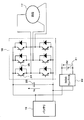
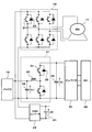
- FIG. 2 is a diagram illustrating a circuit configuration of a high voltage ISG drive system according to the first embodiment.
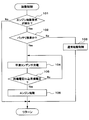
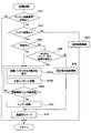
- FIG. 3 is a flowchart showing a start control routine of the first embodiment.
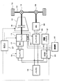
- FIG. 4 is a diagram illustrating a schematic configuration of a drive control system for a hybrid vehicle according to a second embodiment.
- FIG. 5 is a diagram illustrating a circuit configuration of a drive system for the high voltage ISG and the traveling MG according to the second embodiment.
- FIG. 1 is a diagram illustrating a schematic configuration of a vehicle drive control system according to a first embodiment of the present disclosure.
- FIG. 2 is a diagram illustrating a circuit configuration of a high voltage ISG drive system according to the first embodiment.
- FIG. 3 is a flowchart showing a start control routine of the first embodiment.
- FIG. 4 is a diagram illustrating a schematic configuration of
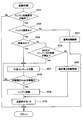
- FIG. 6 is a flowchart showing a start control routine of the second embodiment.
- FIG. 7 is a diagram illustrating a schematic configuration of a drive control system for a hybrid vehicle according to a third embodiment.
- FIG. 8 is a diagram illustrating a circuit configuration of a driving system for the high voltage ISG and the traveling MG according to the third embodiment.
- FIG. 9 is a flowchart showing a start control routine of the third embodiment.
- Example 1 A first embodiment of the present disclosure will be described with reference to FIGS. 1 to 3.
- An engine 11 that is an internal combustion engine is mounted as a power source of the vehicle.
- the power of the output shaft (crankshaft) of the engine 11 is transmitted to the transmission 12, and the power of the output shaft of the transmission 12 is transmitted to the wheels 15 via the differential gear mechanism 13, the axle 14 and the like.
- the transmission 12 may be a stepped transmission that switches the shift speed step by step from among a plurality of shift speeds, or may be a CVT (continuously variable transmission) that changes continuously.
- a clutch 16 for interrupting power transmission is incorporated in the transmission 12.
- the clutch 16 may be a hydraulically driven hydraulic clutch or an electromagnetically driven electromagnetic clutch.
- the clutch 15 may be provided separately from the transmission 12 (for example, disposed between the engine 11 and the transmission 12).
- a high voltage ISG (integrated starter generator) 17 also serving as a generator is provided as a starter for cranking the engine 11.
- the high voltage ISG 17 is constituted by an AC motor or the like driven by an inverter 18 described later.
- the high voltage battery 19 is constituted by a secondary battery such as a lithium ion battery or a nickel metal hydride battery that outputs a high voltage of 200 to 300 V, for example.
- the auxiliary battery 21 is configured by a secondary battery such as a lead storage battery that outputs a low voltage of 12 V, for example.
- the ISG inverter 18 that drives the high voltage ISG 17 is connected to the high voltage battery 19, and the high voltage ISG 17 exchanges power with the high voltage battery 19 via the ISG inverter 18. Further, the alternator 22 driven by the power of the engine 11 is connected to the auxiliary battery 21, and the generated power of the alternator 22 is charged to the auxiliary battery 21.
- a bidirectional DCDC converter 23 is connected between the auxiliary battery 21 and the high voltage battery 19.
- the bidirectional DCDC converter 23 has a function of boosting the voltage on the auxiliary battery 21 side (for example, the output voltage of the auxiliary battery 21 or the generated voltage of the alternator 22) and outputting the boosted voltage to the high voltage battery 19 side. Further, it has a function of stepping down the voltage on the high voltage battery 19 side (for example, the output voltage of the high voltage battery 19 or the generated voltage of the high voltage ISG 17) and outputting it to the auxiliary battery 21 side.
- the ISG inverter 18 is provided with six switching elements 24 (a switching element for each phase of the upper arm and a switching element for each phase of the lower arm).
- a reflux diode 25 is connected in parallel.
- the inverter 18 for ISG converts the DC power of the high voltage battery 19 into three-phase AC power to drive the high voltage ISG 17, or converts the three-phase AC power generated by the high voltage ISG 17 into DC power.
- the high voltage battery 19 is charged.
- a smoothing capacitor 26 is connected between the high voltage battery 19 and the ISG inverter 18. The smoothing capacitor 26 may be incorporated in the ISG inverter 18.
- the engine 11, the transmission 12, the ISG inverter 18, the bidirectional DCDC converter 23, and the like are controlled by an electronic control unit (hereinafter referred to as ECU) 27.
- the engine 11, the transmission 12, the ISG inverter 18, the bidirectional DCDC converter 23, and the like may be controlled by a plurality of ECUs.
- the ECU 27 reads the output signals of various sensors and switches, detects the driving state of the vehicle, and according to the driving state of the vehicle, the engine 11, the transmission 12, the ISG inverter 18, the bidirectional DCDC converter 23. Control etc.
- the ECU 27 performs the following start control by executing a start control routine shown in FIG.
- the boost power start control is executed.
- the output voltage of the auxiliary battery 21 is boosted by the bidirectional DCDC converter 23, and the electric energy (for starting the engine 11 is supplied to the smoothing capacitor 26 by the output power of the bidirectional DCDC converter 23. Charge).
- the engine 11 is cranked by starting the engine 11 by driving the high voltage ISG 17 with the electric energy charged in the smoothing capacitor 26.
- the start control routine shown in FIG. 3 is repeatedly executed at a predetermined period during the power-on period of the ECU 27, and corresponds to the start control unit of the present disclosure.
- S101 determines whether or not the high-voltage battery abnormality in which the high-voltage battery 19 has failed or is insufficiently charged.
- S102 corresponds to an example of the high voltage battery determination unit of the present disclosure.
- whether or not the failure of the high voltage battery 19 has occurred is, for example, whether or not the output voltage of the high voltage battery 19 is lower than a predetermined value (for example, the minimum value of the output voltage necessary for starting the engine 11). Whether the sensor for detecting the output voltage of the high voltage battery 19 has failed or not is determined.
- the SOC discharged state
- a predetermined value for example, the minimum value of SOC required for starting the engine 11. Whether or not is determined.
- the SOC is defined by the following equation 1, for example.
- SOC remaining capacity / full charge capacity ⁇ 100 (Equation 1) If it is determined in S102 that the high-voltage battery is not abnormal, it is determined that sufficient power can be supplied from the high-voltage battery 19 to the high-voltage ISG 17, and the process proceeds to S103 and normal start control is executed. In this normal start control, the engine 11 is cranked by starting the engine 11 by driving the high voltage ISG 17 with the electric power of the high voltage battery 19.
- the output voltage of the auxiliary battery 21 is boosted by the bidirectional DCDC converter 23, and the smoothing capacitor 26 is charged with electric energy by the output power of the bidirectional DCDC converter 23.
- the process proceeds to S105, and whether or not the electric energy charged in the smoothing capacitor 26 is equal to or higher than the electric energy necessary for starting the engine 11 depending on whether or not the voltage Vc across the smoothing capacitor 26 is equal to or higher than the target voltage.
- the target voltage is set to a voltage value at which the electric energy charged in the smoothing capacitor 26 is equal to or higher than the electric energy necessary for starting the engine 11.
- the boost power start control is executed.
- the output voltage of the auxiliary battery 21 is boosted by the bidirectional DCDC converter 23, and the smoothing capacitor 26 is charged with electric energy by the output power of the bidirectional DCDC converter 23.
- the engine 11 is started by driving the high voltage ISG 17 with the electric energy charged in the smoothing capacitor 26.
- the engine 11 can be started by driving the high voltage ISG 17 with the power of the auxiliary battery 21 by the boost power start control.
- the smoothing capacitor 26 is temporarily charged with the electric energy necessary for starting the engine 11, and the high voltage ISG 17 is driven by the electric energy charged in the smoothing capacitor 26.
- the smoothing capacitor 26 it is possible to suppress sudden fluctuations in the voltage of the auxiliary battery 21 due to power consumption of the high voltage ISG 17 and the accompanying adverse effects on the auxiliary machines 20 and to suppress an increase in instantaneous energization power of the bidirectional DCDC converter 23.
- the rated power of the bidirectional DCDC converter 23 can be lowered.
- Example 2 a second embodiment in which the present disclosure is applied to a hybrid vehicle will be described with reference to FIGS. 4 to 6.
- substantially the same parts as those in the first embodiment are denoted by the same reference numerals, and the description thereof is omitted or simplified, and the parts different from the first embodiment will be mainly described.
- an engine 11 and a traveling MG (motor generator) 28 are mounted as a power source of the vehicle.
- the power of the output shaft of the traveling MG 28 is transmitted to the wheel 15 via the differential gear mechanism 29, the axle 14 and the like.
- the MG inverter 30 that drives the traveling MG 28 is connected to the high voltage battery 19, and the traveling MG 28 exchanges power with the high voltage battery 19 via the MG inverter 30.
- a smoothing capacitor 26 is connected between the high voltage battery 19 and the MG inverter 30.
- the smoothing capacitor 26 may be incorporated in the MG inverter 30.
- the ECU 27 switches the traveling mode between, for example, an engine traveling mode, an HV traveling mode, and an EV traveling mode according to the driving state of the vehicle.
- engine travel mode engine travel is performed in which the vehicle 15 travels by driving the wheels 15 with only the power of the engine 11 out of the engine 11 and the travel MG 28.
- HV traveling mode HV traveling is performed in which the vehicle 15 is driven by driving the wheels 15 with both the power of the engine 11 and the power of the traveling MG 28.
- EV traveling mode EV traveling is performed in which the combustion of the engine 11 is stopped and the vehicle 15 is driven by driving the wheels 15 only with the power of the traveling MG 28 of the engine 11 and the traveling MG 28.
- regenerative power generation is performed by converting the kinetic energy of the vehicle into electric energy by the traveling MG 28 and the generated power is charged (collected) in the high voltage battery 19.
- the engine 11 can be started by driving the high voltage ISG 17 with the generated power of the regenerative power generation if the regenerative power generation can be performed even when the high voltage battery is abnormal.
- S201 it is determined whether or not a start request for the engine 11 has occurred.
- S202 it is determined whether the high-voltage battery 19 is malfunctioning or insufficiently charged.
- S204 and 205 correspond to an example of the regenerative power generation determination unit of the present disclosure.
- the process proceeds to S204, where it is determined whether or not the vehicle is stopped. If it is determined in S204 that the vehicle is not stopped (that is, the vehicle is traveling), the process proceeds to S205, in which it is determined whether a failure of the traveling MG 28 or the MG inverter 30 has occurred.
- the boost power start control (S207 to 209) is executed as follows.
- the output voltage of the auxiliary battery 21 is boosted by the bidirectional DCDC converter 23, and the smoothing capacitor 26 is charged with electric energy by the output power of the bidirectional DCDC converter 23.
- the process proceeds to S208, and it is determined whether or not the voltage Vc across the smoothing capacitor 26 is equal to or higher than the target voltage. If it is determined in S208 that the voltage Vc across the smoothing capacitor 26 is lower than the target voltage, the process returns to S207.
- S210 corresponds to an example of the fail-safe unit of the present disclosure.
- the boost power start control when a start request for the engine 11 is generated, if it is determined that the high voltage battery is abnormal and it is determined that regenerative power generation cannot be performed, the boost power start control is executed. Yes.
- the engine 11 can be started by driving the high voltage ISG 17 with the electric power of the auxiliary battery 21 by the boosted power start control.
- the boost power start control is not performed. Therefore, it is possible to prevent the boost power start control from being performed more than necessary, and the auxiliary machine based on the boost power start control. The power consumption of the battery 21 can be suppressed.
- the mode is switched to the retreat travel mode in which EV travel is prohibited.
- the boost power start control it can be avoided that the boost power start control is executed again and again, and the power consumption of the auxiliary battery 21 by the boost power start control is suppressed. can do.
- Example 3 a third embodiment in which the present disclosure is applied to a hybrid vehicle will be described with reference to FIGS. 7 to 9.
- substantially the same parts as those in the second embodiment are denoted by the same reference numerals, the description thereof is omitted or simplified, and different parts from the second embodiment are mainly described.
- a boost converter 31 is connected between the high voltage battery 19 and the MG inverter 30.
- This boost converter 31 has a function of boosting the voltage on the high voltage battery 19 side and outputting it to the MG inverter 30 side, or a function of stepping down the voltage on the MG inverter 30 side and outputting it to the high voltage battery 19 side. .
- a smoothing capacitor 26 is connected between the boost converter 31 and the MG inverter 30.
- the smoothing capacitor 26 may be incorporated in the MG inverter 30.
- the boost converter 31 is provided with an input capacitor 32, a reactor 33, and two switching elements 34, and a free-wheeling diode 35 is connected in parallel to each switching element 34.
- the ECU 27 executes a start control routine shown in FIG. 9 to be described later, whereby the output voltage of the bidirectional DCDC converter 23 is further boosted by the boost converter 31 during the boost power start control.
- the smoothing capacitor 26 is charged by the output power 31.
- the routine of FIG. 9 executed in the third embodiment is obtained by changing the processing of S207 of the routine of FIG. 6 described in the second embodiment to the processing of S207a and 207b. Same as 6.
- the boost power start control (S207a to 209) is executed as follows.
- the output voltage of the auxiliary battery 21 is boosted by the bidirectional DCDC converter 23.
- the output voltage of the bidirectional DCDC converter 23 is boosted by the boost converter 31, and the smoothing capacitor 26 is charged with electric energy by the output power of the boost converter 31.
- the process proceeds to S208, and it is determined whether or not the voltage Vc across the smoothing capacitor 26 is equal to or higher than the target voltage. If it is determined in S208 that the voltage Vc across the smoothing capacitor 26 is lower than the target voltage, the process returns to S207a.
- the output voltage of the auxiliary battery 21 is boosted by the bidirectional DCDC converter 23, and the output voltage of the bidirectional DCDC converter 23 is further boosted by the boost converter 31.
- the smoothing capacitor 26 is charged with electric energy by the output power of the boost converter 31.
- the output voltage of the auxiliary battery 21 can be boosted in two stages, ie, the bidirectional DCDC converter 23 and the boost converter 31, and charged to the smoothing capacitor 26. Therefore, compared to the case where the boost converter 31 does not boost the voltage, The electric energy which can be charged can be increased even if the capacitance of 26 is the same. For this reason, compared with the case where the boosting converter 31 does not boost the voltage, the capacitance of the capacitor 26 required for charging the electric energy required for starting the engine 11 can be reduced, and the capacitor 26 can be downsized. Can do.
- the present disclosure is applied to a system including a high voltage ISG 17 that also serves as a generator as a starter for cranking the engine 11.
- the present disclosure is not limited to this.
- the present disclosure may be applied to a system including a high-voltage starter that does not have a generator function or a system that uses an MG serving as a power source of a vehicle as a starter.
- some or all of the functions executed by the ECU 27 may be configured by hardware using one or a plurality of ICs.
- the output voltages of the high voltage battery 19 and the auxiliary battery 21 are not limited to the ranges described in the above embodiments, and may be changed as appropriate.
- the present disclosure can be applied to any vehicle including a plurality of secondary batteries having different output voltages, such as a secondary battery that outputs a voltage of 24 V as an auxiliary battery.
- EV travel is prohibited in the retreat travel mode.
- the purpose is to prevent the boost power start control from being repeatedly executed. It is not limited to prohibition.
- the idle stop may be prohibited in the retreat travel mode.
- the present disclosure is not limited to the hybrid vehicle having the configuration illustrated in FIGS. 4 and 7, and is a hybrid vehicle having various configurations in which an engine and MG are mounted as a power source of the vehicle (for example, a hybrid vehicle having a plurality of MGs mounted). ).
- each step is expressed as S101, for example. Further, each step can be divided into a plurality of sub-steps, while a plurality of steps can be combined into one step.
Landscapes
- Engineering & Computer Science (AREA)
- Chemical & Material Sciences (AREA)
- Combustion & Propulsion (AREA)
- Mechanical Engineering (AREA)
- Transportation (AREA)
- General Engineering & Computer Science (AREA)
- Automation & Control Theory (AREA)
- Power Engineering (AREA)
- Health & Medical Sciences (AREA)
- Biomedical Technology (AREA)
- General Health & Medical Sciences (AREA)
- Hybrid Electric Vehicles (AREA)
- Electric Propulsion And Braking For Vehicles (AREA)
- Control Of Vehicle Engines Or Engines For Specific Uses (AREA)
Abstract
車両の制御装置は、エンジンと、スタータ(17)と、補機バッテリ(21)と、高電圧バッテリ(19)とを備える。車両の制御装置は、補機バッテリと高電圧バッテリとの間に接続されたDCDCコンバータ(23)と、高電圧バッテリ側の回路に接続されたコンデンサ(26)と、高電圧バッテリ判定部と、始動制御部とを備えている。始動制御部は、補機バッテリの出力電圧をDCDCコンバータで昇圧して該DCDCコンバータの出力電力によりコンデンサにエンジンの始動に必要な電気エネルギを充電し、該コンデンサに充電された電気エネルギでスタータを駆動してエンジンを始動する昇圧電力始動制御を実行する。
Description
本出願は、2015年8月21日に出願された日本国特許出願2015-163980号に基づくものであり、ここにその記載内容を参照により援用する。
本開示は、高電圧バッテリの電力でスタータを駆動してエンジンを始動する車両の制御装置に関する。
近年、低燃費や低排気エミッション等の社会的要請から車両の動力源としてエンジンとMG(モータジェネレータ)とを搭載したハイブリッド車が注目されている。このようなハイブリッド車においては、例えば、特許文献1に記載されたものがある。このものは、高電圧バッテリ(蓄電装置)に接続されたMGをスタータとして用い、高電圧バッテリの電力でMGを駆動することでエンジンをクランキングしてエンジンを始動するようにしている。また、車両の走行中にエンジンの始動要求が発生したときに、高電圧バッテリの故障等により高電圧バッテリからMGに十分な電力を供給できない場合には、車両の運動エネルギをMGで電気エネルギに変換する回生発電を行って、その発電電力を利用してエンジンを始動するようにしている。
特許文献1の技術では、高電圧バッテリの故障等により高電圧バッテリからMGに十分な電力を供給できない高電圧バッテリ異常時に、車両の停車中で回生発電を行うことができない場合、或は、MGやインバータの故障で回生発電を行うことができない場合には、エンジンを始動することができないおそれがある。
本開示の目的は、高電圧バッテリの電力でスタータを駆動してエンジンを始動するシステムにおいて、高電圧バッテリ異常時でもスタータを駆動してエンジンを始動することができる車両の制御装置を提供することにある。
本開示の一例によれば、車両の制御装置は、車両の動力源となるエンジンと、該エンジンをクランキングするスタータと、車両の補機類に電力を供給する補機バッテリと、スタータに電力を供給すると共に補機バッテリよりも出力電圧が高い高電圧バッテリとを備える。車両の制御装置は、補機バッテリと高電圧バッテリとの間に接続されたDCDCコンバータと、高電圧バッテリ側の回路に接続されたコンデンサと、高電圧バッテリの故障又は充電不足が発生している高電圧バッテリ異常であるか否かを判定する高電圧バッテリ判定部と、エンジンの始動要求が発生したときに、高電圧バッテリ判定部により高電圧バッテリ異常と判定された場合に、補機バッテリの出力電圧をDCDCコンバータで昇圧して該DCDCコンバータの出力電力によりコンデンサにエンジンの始動に必要な電気エネルギを充電し、該コンデンサに充電された電気エネルギでスタータを駆動してエンジンを始動する昇圧電力始動制御を実行する始動制御部とを備えている。
この構成によれば、エンジンの始動要求が発生したときに、高電圧バッテリ異常と判定された場合には、昇圧電力始動制御を実行する。この昇圧電力始動制御では、補機バッテリの出力電圧をDCDCコンバータで昇圧して該DCDCコンバータの出力電力によりコンデンサに電気エネルギを充電し、このコンデンサに充電された電気エネルギでスタータを駆動してエンジンを始動するようにしている。これにより、高電圧バッテリ異常時でも補機バッテリの電力でスタータを駆動してエンジンを始動することができる。
しかも、エンジンの始動に必要な電気エネルギを、一旦、コンデンサに充電し、コンデンサに充電された電気エネルギでスタータを駆動するようにしている。これにより、スタータの電力消費による補機バッテリの電圧の急変動やそれに伴う補機類への悪影響を抑制することができると共に、DCDCコンバータの瞬時通電電力の増大を抑制することができる。また、次回のエンジン始動に備えて高電圧バッテリのSOC(充電状態)を常にエンジン始動に必要な値以上に維持しておくといった必要がなく、高電圧バッテリのSOCの使用範囲の下限を低くすることができる。
本開示についての上記および他の目的、特徴や利点は、添付図面を参照した下記詳細な説明から、より明確になる。添付図面において、
図1は本開示の実施例1における車両の駆動制御システムの概略構成を示す図であり、
図2は実施例1の高電圧ISGの駆動システムの回路構成を示す図であり、
図3は実施例1の始動制御ルーチンを示すフローチャートであり、
図4は実施例2のハイブリッド車の駆動制御システムの概略構成を示す図であり、
図5は実施例2の高電圧ISG及び走行用MGの駆動システムの回路構成を示す図であり、
図6は実施例2の始動制御ルーチンを示すフローチャートであり、
図7は実施例3のハイブリッド車の駆動制御システムの概略構成を示す図であり、
図8は実施例3の高電圧ISG及び走行用MGの駆動システムの回路構成を示す図であり、
図9は実施例3の始動制御ルーチンを示すフローチャートである。
以下、本開示を実施するための形態を具体化した幾つかの実施例を説明する。
(実施例1)
本開示の実施例1を図1乃至図3に基づいて説明する。
(実施例1)
本開示の実施例1を図1乃至図3に基づいて説明する。
まず、図1に基づいて車両の駆動制御システムの概略構成を説明する。
車両の動力源として内燃機関であるエンジン11が搭載されている。このエンジン11の出力軸(クランク軸)の動力が変速機12に伝達され、この変速機12の出力軸の動力がディファレンシャルギヤ機構13や車軸14等を介して車輪15に伝達される。変速機12は、複数の変速段の中から変速段を段階的に切り換える有段変速機であっても良いし、無段階に変速するCVT(無段変速機)であっても良い。この変速機12には、動力伝達を断続するためのクラッチ16が組み込まれている。このクラッチ16は、油圧駆動式の油圧クラッチであっても良いし、電磁駆動式の電磁クラッチであっても良い。尚、クラッチ15は、変速機12とは別に設ける(例えばエンジン11と変速機12との間に配置する)ようにしても良い。
また、エンジン11をクランキングするスタータとしてジェネレータ兼用の高電圧ISG(インテグレーテッドスタータジェネレータ)17が設けられている。この高電圧ISG17は、後述するインバータ18で駆動される交流モータ等により構成されている。この高電圧ISG17に電力を供給する高電圧バッテリ19と、車両の補機類20(例えば、ブロアファン、ヘッドライト、ワイパー等の電装品)に電力を供給する補機バッテリ21(低電圧バッテリに相当)とが搭載されている。高電圧バッテリ19は、例えば、200~300Vの高電圧を出力するリチウムイオン電池やニッケル水素電池等の二次電池により構成されている。一方、補機バッテリ21は、例えば、12Vの低電圧を出力する鉛蓄電池等の二次電池により構成されている。
高電圧ISG17を駆動するISG用インバータ18が高電圧バッテリ19に接続され、高電圧ISG17がISG用インバータ18を介して高電圧バッテリ19と電力を授受する。また、エンジン11の動力で駆動されるオルタネータ22が補機バッテリ21に接続され、オルタネータ22の発電電力が補機バッテリ21に充電される。
更に、補機バッテリ21と高電圧バッテリ19との間には、双方向DCDCコンバータ23が接続されている。この双方向DCDCコンバータ23は、補機バッテリ21側の電圧(例えば補機バッテリ21の出力電圧やオルタネータ22の発電電圧)を昇圧して高電圧バッテリ19側に出力する機能を有する。更に、高電圧バッテリ19側の電圧(例えば高電圧バッテリ19の出力電圧や高電圧ISG17の発電電圧)を降圧して補機バッテリ21側に出力する機能も有する。
図2に示すように、ISG用インバータ18には、六つのスイッチング素子24(上アームの各相のスイッチング素子と下アームの各相のスイッチング素子)が設けられ、各スイッチング素子24には、それぞれ還流ダイオード25が並列に接続されている。このISG用インバータ18は、高電圧バッテリ19の直流電力を三相の交流電力に変換して高電圧ISG17を駆動したり、高電圧ISG17で発電した三相の交流電力を直流電力に変換して高電圧バッテリ19に充電する。また、高電圧バッテリ19とISG用インバータ18との間には、平滑コンデンサ26が接続されている。尚、平滑コンデンサ26がISG用インバータ18に組み込まれた構成としても良い。
図1に示すように、エンジン11、変速機12、ISG用インバータ18、双方向DCDCコンバータ23等は、電子制御ユニット(以下、ECUと表記)27によって制御される。尚、エンジン11、変速機12、ISG用インバータ18、双方向DCDCコンバータ23等を複数のECUで制御する構成としても良い。ECU27は、各種のセンサやスイッチの出力信号を読み込んで、車両の運転状態を検出し、その車両の運転状態等に応じて、エンジン11、変速機12、ISG用インバータ18、双方向DCDCコンバータ23等を制御する。
また、本実施例1では、ECU27により後述する図3の始動制御ルーチンを実行することで、次のような始動制御を行う。
エンジン11の始動要求が発生したときに、高電圧バッテリ19の故障又は充電不足が発生している高電圧バッテリ異常であるか否かを判定する。その結果、高電圧バッテリ異常ではないと判定された場合には、高電圧バッテリ19から高電圧ISG17に十分な電力を供給できると判断して、通常始動制御を実行する。この通常始動制御では、高電圧バッテリ19の電力で高電圧ISG17を駆動することでエンジン11をクランキングしてエンジン11を始動する。
一方、高電圧バッテリ異常と判定された場合には、高電圧バッテリ19から高電圧ISG17に十分な電力を供給できないと判断して、昇圧電力始動制御を実行する。この昇圧電力始動制御では、まず、補機バッテリ21の出力電圧を双方向DCDCコンバータ23で昇圧し、この双方向DCDCコンバータ23の出力電力により平滑コンデンサ26にエンジン11の始動に必要な電気エネルギ(電力量)を充電する。この後、平滑コンデンサ26に充電された電気エネルギで高電圧ISG17を駆動することでエンジン11をクランキングしてエンジン11を始動する。
以下、本実施例1でECU27が実行する図3の始動制御ルーチンの処理内容を説明する。
図3に示す始動制御ルーチンは、ECU27の電源オン期間中に所定周期で繰り返し実行され、本開示の始動制御部に相当する。
本ルーチンが起動されると、まず、S101で、エンジン11の始動要求が発生したか否かを判定する。このS101で、エンジン11の始動要求が発生していないと判定された場合には、S102以降の処理を実行することなく、本ルーチンを終了する。
その後、上記S101で、エンジン11の始動要求が発生したと判定された時点で、S102に進み、高電圧バッテリ19の故障又は充電不足が発生している高電圧バッテリ異常であるか否かを判定する。S102は本開示の高電圧バッテリ判定部の一例に対応する。
ここで、高電圧バッテリ19の故障が発生しているか否かは、例えば、高電圧バッテリ19の出力電圧が所定値(例えばエンジン11の始動に必要な出力電圧の最小値)よりも低いか否か、高電圧バッテリ19の出力電圧を検出するセンサが故障しているか否か等によって判定する。
また、高電圧バッテリ19の充電不足が発生しているか否かは、例えば、高電圧バッテリ19のSOC(充電状態)が所定値(例えばエンジン11の始動に必要なSOCの最小値)よりも低いか否等によって判定する。SOCは、例えば、次式1により定義される。
SOC=残容量/満充電容量×100 ・・・(式1)
このS102で、高電圧バッテリ異常ではないと判定された場合には、高電圧バッテリ19から高電圧ISG17に十分な電力を供給できると判断して、S103に進み、通常始動制御を実行する。この通常始動制御では、高電圧バッテリ19の電力で高電圧ISG17を駆動することでエンジン11をクランキングしてエンジン11を始動する。
このS102で、高電圧バッテリ異常ではないと判定された場合には、高電圧バッテリ19から高電圧ISG17に十分な電力を供給できると判断して、S103に進み、通常始動制御を実行する。この通常始動制御では、高電圧バッテリ19の電力で高電圧ISG17を駆動することでエンジン11をクランキングしてエンジン11を始動する。
これに対して、上記S102で、高電圧バッテリ異常と判定された場合には、高電圧バッテリ19から高電圧ISG17に十分な電力を供給できないと判断して、昇圧電力始動制御(S104~106)を次のようにして実行する。
まず、S104で、補機バッテリ21の出力電圧を双方向DCDCコンバータ23で昇圧し、この双方向DCDCコンバータ23の出力電力により平滑コンデンサ26に電気エネルギを充電する。
この後、S105に進み、平滑コンデンサ26の両端電圧Vc が目標電圧以上であるか否かによって、平滑コンデンサ26に充電された電気エネルギがエンジン11の始動に必要な電気エネルギ以上であるか否かを判定する。ここで、目標電圧は、平滑コンデンサ26に充電された電気エネルギがエンジン11の始動に必要な電気エネルギ以上となる電圧値に設定されている。
このS105で、平滑コンデンサ26の両端電圧Vc が目標電圧よりも低いと判定された場合には、平滑コンデンサ26に充電された電気エネルギがエンジン11の始動に必要な電気エネルギに達していないと判断して、上記S104に戻る。
その後、上記S105で、平滑コンデンサ26の両端電圧Vc が目標電圧以上と判定された時点で、平滑コンデンサ26に充電された電気エネルギがエンジン11の始動に必要な電気エネルギ以上になったと判断して、S106に進む。このS106で、平滑コンデンサ26に充電された電気エネルギで高電圧ISG17を駆動することでエンジン11をクランキングしてエンジン11を始動する。
以上説明した本実施例1では、エンジン11の始動要求が発生したときに、高電圧バッテリ異常と判定された場合には、昇圧電力始動制御を実行する。この昇圧電力始動制御では、まず、補機バッテリ21の出力電圧を双方向DCDCコンバータ23で昇圧し、この双方向DCDCコンバータ23の出力電力により平滑コンデンサ26に電気エネルギを充電する。この後、平滑コンデンサ26に充電された電気エネルギで高電圧ISG17を駆動してエンジン11を始動する。これにより、高電圧バッテリ異常時でも、昇圧電力始動制御により補機バッテリ21の電力で高電圧ISG17を駆動してエンジン11を始動することができる。
しかも、エンジン11の始動に必要な電気エネルギを、一旦、平滑コンデンサ26に充電し、平滑コンデンサ26に充電された電気エネルギで高電圧ISG17を駆動するようにしている。これにより、高電圧ISG17の電力消費による補機バッテリ21の電圧の急変動やそれに伴う補機類20への悪影響を抑制することができると共に、双方向DCDCコンバータ23の瞬時通電電力の増大を抑制することができ、双方向DCDCコンバータ23の定格電力を低くすることができる。また、次回のエンジン始動に備えて高電圧バッテリ19のSOCを常にエンジン始動に必要な値以上に維持しておくといった必要がなく、高電圧バッテリ19のSOCの使用範囲の下限を低くすることができるという利点もある。
(実施例2)
次に、図4乃至図6を用いて本開示をハイブリッド車に適用した実施例2を説明する。但し、実施例1と実質的に同一部分には同一符号を付して説明を省略又は簡略化し、主として実施例1と異なる部分について説明する。
(実施例2)
次に、図4乃至図6を用いて本開示をハイブリッド車に適用した実施例2を説明する。但し、実施例1と実質的に同一部分には同一符号を付して説明を省略又は簡略化し、主として実施例1と異なる部分について説明する。
本実施例2では、図4に示すように、車両の動力源としてエンジン11と走行用MG(モータジェネレータ)28とが搭載されている。この走行用MG28の出力軸の動力がディファレンシャルギヤ機構29や車軸14等を介して車輪15に伝達される。走行用MG28を駆動するMG用インバータ30が高電圧バッテリ19に接続され、走行用MG28がMG用インバータ30を介して高電圧バッテリ19と電力を授受する。
また、図5に示すように、高電圧バッテリ19とMG用インバータ30との間に、平滑コンデンサ26が接続されている。尚、平滑コンデンサ26がMG用インバータ30に組み込まれた構成としても良い。
ECU27は、車両の運転状態等に応じて、走行モードを、例えば、エンジン走行モードとHV走行モードとEV走行モードとの間で切り換える。エンジン走行モードでは、エンジン11と走行用MG28のうちエンジン11の動力のみで車輪15を駆動して車両を走行させるエンジン走行を行う。HV走行モードでは、エンジン11の動力と走行用MG28の動力の両方で車輪15を駆動して車両を走行させるHV走行を行う。EV走行モードでは、エンジン11の燃焼を停止してエンジン11と走行用MG28のうち走行用MG28の動力のみで車輪15を駆動して車両を走行させるEV走行を行う。また、車両の減速時等には、車両の運動エネルギを走行用MG28で電気エネルギに変換する回生発電を行って、その発電電力を高電圧バッテリ19に充電(回収)する。
ところで、ハイブリッド車の場合には、高電圧バッテリ異常時でも、回生発電を実行可能であれば、回生発電の発電電力で高電圧ISG17を駆動してエンジン11を始動することができる。
そこで、本実施例2では、ECU27により後述する図6の始動制御ルーチンを実行することで、エンジン11の始動要求が発生したときに、高電圧バッテリ異常と判定された場合には、回生発電を実行できるか否かを判定し、高電圧バッテリ異常と判定され且つ回生発電を実行できないと判定された場合に、昇圧電力始動制御を実行する。
以下、本実施例2でECU27が実行する図6の始動制御ルーチンの処理内容を説明する。
図6に示す始動制御ルーチンでは、まず、S201で、エンジン11の始動要求が発生したか否かを判定する。このS201で、エンジン11の始動要求が発生したと判定された時点で、S202に進み、高電圧バッテリ19の故障又は充電不足が発生している高電圧バッテリ異常であるか否かを判定する。
このS202で、高電圧バッテリ異常ではないと判定された場合には、高電圧バッテリ19から高電圧ISG17に十分な電力を供給できると判断して、S203に進み、通常始動制御を実行する。
これに対して、上記S202で、高電圧バッテリ異常と判定された場合には、高電圧バッテリ19から高電圧ISG17に十分な電力を供給できないと判断して、次のS204,205で、回生発電を実行できるか否かを判定する。S204,205は本開示の回生発電判定部の一例に対応する。
まず、S204に進み、車両が停車中であるか否かを判定する。このS204で、車両が停車中ではない(つまり走行中)と判定された場合には、S205に進み、走行用MG28又はMG用インバータ30の故障が発生しているか否かを判定する。
上記S204で車両が停車中と判定された場合、又は、上記S205で走行用MG28又はMG用インバータ30の故障が発生していると判定された場合には、回生発電を実行できないと判断する。この場合、つまり、高電圧バッテリ異常と判定され且つ回生発電を実行できないと判定された場合には、昇圧電力始動制御(S207~209)を次のようにして実行する。
まず、S207で、補機バッテリ21の出力電圧を双方向DCDCコンバータ23で昇圧し、この双方向DCDCコンバータ23の出力電力により平滑コンデンサ26に電気エネルギを充電する。
この後、S208に進み、平滑コンデンサ26の両端電圧Vc が目標電圧以上であるか否かを判定する。このS208で、平滑コンデンサ26の両端電圧Vc が目標電圧よりも低いと判定された場合には、上記S207に戻る。
その後、上記S208で、平滑コンデンサ26の両端電圧Vc が目標電圧以上と判定された時点で、S209に進み、平滑コンデンサ26に充電された電気エネルギで高電圧ISG17を駆動することでエンジン11をクランキングしてエンジン11を始動する。
この後、S210に進み、退避走行モードに切り換える。この退避走行モードでは、EV走行を禁止する。更に、車両の速度、エンジン11の出力やトルク等を制限するようにしても良い。S210は本開示のフェールセーフ部の一例に対応する。
これに対して、上記S204で車両が停車中ではない(つまり走行中)と判定され、且つ、上記S205で走行用MG28とMG用インバータ30が両方とも故障していない(つまり正常)と判定された場合には、回生発電を実行できると判断する。この場合、S206に進み、回生電力始動制御を実行する。この回生電力始動制御では、車両の運動エネルギを走行用MG28で電気エネルギに変換する回生発電を行って、その発電電力で高電圧ISG17を駆動することでエンジン11をクランキングしてエンジン11を始動する。この後、S210に進み、退避走行モードに切り換える。
以上説明した本実施例2では、エンジン11の始動要求が発生したときに、高電圧バッテリ異常と判定され且つ回生発電を実行できないと判定された場合に、昇圧電力始動制御を実行するようにしている。これにより、高電圧バッテリ異常時で且つ回生発電を実行できない場合でも、昇圧電力始動制御により補機バッテリ21の電力で高電圧ISG17を駆動してエンジン11を始動することができる。また、高電圧バッテリ異常時でも回生発電を実行可能な場合には、昇圧電力始動制御を実行しないため、必要以上に昇圧電力始動制御を実行することを防止して、昇圧電力始動制御による補機バッテリ21の電力消費を抑制することができる。
更に、本実施例2では、昇圧電力始動制御によりエンジン11が始動された後に、EV走行を禁止する退避走行モードに切り換えるようにしている。これにより、昇圧電力始動制御によりエンジン11が始動された後に、再び昇圧電力始動制御が何回も実行されることを回避することができ、昇圧電力始動制御による補機バッテリ21の電力消費を抑制することができる。
(実施例3)
次に、図7乃至図9を用いて本開示をハイブリッド車に適用した実施例3を説明する。但し、実施例2と実質的に同一部分には同一符号を付して説明を省略又は簡略化し、主として実施例2と異なる部分について説明する。
(実施例3)
次に、図7乃至図9を用いて本開示をハイブリッド車に適用した実施例3を説明する。但し、実施例2と実質的に同一部分には同一符号を付して説明を省略又は簡略化し、主として実施例2と異なる部分について説明する。
本実施例3では、図7に示すように、高電圧バッテリ19とMG用インバータ30との間に、昇圧コンバータ31が接続されている。この昇圧コンバータ31は、高電圧バッテリ19側の電圧を昇圧してMG用インバータ30側に出力する機能や、MG用インバータ30側の電圧を降圧して高電圧バッテリ19側に出力する機能を有する。
また、図8に示すように、昇圧コンバータ31とMG用インバータ30との間に、平滑コンデンサ26が接続されている。尚、平滑コンデンサ26がMG用インバータ30に組み込まれた構成としても良い。昇圧コンバータ31には、入力コンデンサ32とリアクトル33と二つのスイッチング素子34が設けられ、各スイッチング素子34に、それぞれ還流ダイオード35が並列に接続されている。
本実施例3では、ECU27により後述する図9の始動制御ルーチンを実行することで、昇圧電力始動制御の際に、双方向DCDCコンバータ23の出力電圧を昇圧コンバータ31で更に昇圧し、この昇圧コンバータ31の出力電力により平滑コンデンサ26に充電する。
本実施例3で実行する図9のルーチンは、実施例2で説明した図6のルーチンのS207の処理を、S207a,207bの処理に変更したものであり、それ以外の各Sの処理は図6と同じである。
図9の始動制御ルーチンでは、S204で車両が停車中と判定された場合、又は、S205で走行用MG28又はMG用インバータ30の故障が発生していると判定された場合には、回生発電を実行できないと判断する。この場合、つまり、高電圧バッテリ異常と判定され且つ回生発電を実行できないと判定された場合には、昇圧電力始動制御(S207a~209)を次のようにして実行する。
まず、S207aで、補機バッテリ21の出力電圧を双方向DCDCコンバータ23で昇圧する。更に、S207bで、双方向DCDCコンバータ23の出力電圧を昇圧コンバータ31で昇圧し、この昇圧コンバータ31の出力電力により平滑コンデンサ26に電気エネルギを充電する。
この後、S208に進み、平滑コンデンサ26の両端電圧Vc が目標電圧以上であるか否かを判定する。このS208で、平滑コンデンサ26の両端電圧Vc が目標電圧よりも低いと判定された場合には、上記S207aに戻る。
その後、上記S208で、平滑コンデンサ26の両端電圧Vc が目標電圧以上と判定された時点で、S209に進み、平滑コンデンサ26に充電された電気エネルギで高電圧ISG17を駆動することでエンジン11をクランキングしてエンジン11を始動する。
以上説明した本実施例3では、昇圧電力始動制御の際に、補機バッテリ21の出力電圧を双方向DCDCコンバータ23で昇圧し、この双方向DCDCコンバータ23の出力電圧を昇圧コンバータ31で更に昇圧し、この昇圧コンバータ31の出力電力により平滑コンデンサ26に電気エネルギを充電する。これにより、補機バッテリ21の出力電圧を双方向DCDCコンバータ23と昇圧コンバータ31の二段階で昇圧して平滑コンデンサ26に充電することができるため、昇圧コンバータ31で昇圧しない場合に比べて、コンデンサ26の静電容量が同じでも充電可能な電気エネルギを増加させることができる。このため、昇圧コンバータ31で昇圧しない場合に比べて、エンジン11の始動に必要な電気エネルギを充電するのに必要なコンデンサ26の静電容量を小さくすることができ、コンデンサ26を小型化することができる。
尚、上記各実施例1~3では、エンジン11をクランキングするスタータとしてジェネレータ兼用の高電圧ISG17を備えたシステムに本開示を適用している。しかし、これに限定されず、例えば、ジェネレータ機能を持たない高電圧スタータを備えたシステムや、車両の動力源となるMGをスタータとして用いるシステムに本開示を適用しても良い。
また、上記各実施例1~3において、ECU27が実行する機能の一部又は全部を、一つ或は複数のIC等によりハードウェア的に構成しても良い。
更に、高電圧バッテリ19及び補機バッテリ21の出力電圧は、上記実施例に記載された範囲に限定されず、適宜変更しても良い。例えば、補機バッテリとして24Vの電圧を出力する二次電池を備えていても良い等、出力電圧の異なる複数の二次電池を備えた車両であれば本開示を適用して実施できる。
また、上記実施例では、退避走行モードでEV走行を禁止するようにしているが、その目的は昇圧電力始動制御が繰り返し実行されないようにすることであり、その目的に適う手段であればEV走行禁止に限定されない。例えば、アイドリング中にエンジンを停止するアイドルストップを実施する機能を備えた車両においては、退避走行モードでアイドルストップを禁止するようにしても良い。
その他、本開示は、図4や図7に示す構成のハイブリッド車に限定されず、車両の動力源としてエンジンとMGとを搭載した種々の構成のハイブリッド車(例えば複数のMGを搭載したハイブリッド車)に適用して実施できる。
ここで、この出願に記載されるフローチャート、あるいは、フローチャートの処理は、複数のステップ(あるいはセクションと言及される)から構成され、各ステップは、たとえば、S101と表現される。さらに、各ステップは、複数のサブステップに分割されることができる、一方、複数のステップが合わさって一つのステップにすることも可能である。
以上、本開示に係る車両の制御装置の実施形態、構成、態様を例示したが、本開示に係る実施形態、構成、態様は、上述した各実施形態、各構成、各態様に限定されるものではない。例えば、異なる実施形態、構成、態様にそれぞれ開示された技術的部を適宜組み合わせて得られる実施形態、構成、態様についても本開示に係る実施形態、構成、態様の範囲に含まれる。
Claims (5)
- 車両の動力源となるエンジン(11)と、該エンジンをクランキングするスタータ(17)と、前記車両の補機類(20)に電力を供給する補機バッテリ(21)と、前記スタータに電力を供給すると共に前記補機バッテリよりも出力電圧が高い高電圧バッテリ(19)とを備えた車両の制御装置において、
前記補機バッテリと前記高電圧バッテリとの間に接続されたDCDCコンバータ(23)と、
前記高電圧バッテリ側の回路に接続されたコンデンサ(26)と、
前記高電圧バッテリの故障又は充電不足が発生している高電圧バッテリ異常であるか否かを判定する高電圧バッテリ判定部(27)と、
前記エンジンの始動要求が発生したときに、前記高電圧バッテリ判定部により前記高電圧バッテリ異常と判定された場合に、前記補機バッテリの出力電圧を前記DCDCコンバータで昇圧して該DCDCコンバータの出力電力により前記コンデンサに前記エンジンの始動に必要な電気エネルギを充電し、該コンデンサに充電された電気エネルギで前記スタータを駆動して前記エンジンを始動する昇圧電力始動制御を実行する始動制御部(27)と
を備えている車両の制御装置。 - 前記車両の動力源となるモータジェネレータ(28)と、
前記モータジェネレータと前記高電圧バッテリとの間に接続されたインバータ(30)と、
前記車両の運動エネルギを前記モータジェネレータで電気エネルギに変換する回生発電を実行できるか否かを判定する回生発電判定部(27)とを更に備え、
前記始動制御部は、前記エンジンの始動要求が発生したときに、前記高電圧バッテリ判定部により前記高電圧バッテリ異常と判定され且つ前記回生発電判定部により前記回生発電を実行できないと判定された場合に、前記昇圧電力始動制御を実行する請求項1に記載の車両の制御装置。 - 前記回生発電判定部は、前記車両が停車中の場合か又は前記モータジェネレータと前記インバータのうちの少なくとも一方の故障が発生している場合に、前記回生発電を実行できないと判定する請求項2に記載の車両の制御装置。
- 前記高電圧バッテリと前記インバータとの間に接続された昇圧コンバータ(31)を更に備え、
前記始動制御部は、前記昇圧電力始動制御の際に、前記DCDCコンバータの出力電圧を前記昇圧コンバータで更に昇圧して該昇圧コンバータの出力電力により前記コンデンサに充電する請求項2又は3に記載の車両の制御装置。 - 前記昇圧電力始動制御により前記エンジンが始動された後に、前記エンジンの燃焼を停止して前記モータジェネレータの動力で前記車両を走行させるEV走行を禁止する退避走行モードに切り換えるフェールセーフ部(27)を更に備えている請求項2乃至4のいずれかに記載の車両の制御装置。
Priority Applications (1)
| Application Number | Priority Date | Filing Date | Title |
|---|---|---|---|
| US15/748,623 US10385818B2 (en) | 2015-08-21 | 2016-05-27 | Vehicle control apparatus |
Applications Claiming Priority (2)
| Application Number | Priority Date | Filing Date | Title |
|---|---|---|---|
| JP2015163980A JP6387922B2 (ja) | 2015-08-21 | 2015-08-21 | 車両の制御装置 |
| JP2015-163980 | 2015-08-21 |
Publications (1)
| Publication Number | Publication Date |
|---|---|
| WO2017033354A1 true WO2017033354A1 (ja) | 2017-03-02 |
Family
ID=58099718
Family Applications (1)
| Application Number | Title | Priority Date | Filing Date |
|---|---|---|---|
| PCT/JP2016/002580 Ceased WO2017033354A1 (ja) | 2015-08-21 | 2016-05-27 | 車両の制御装置 |
Country Status (3)
| Country | Link |
|---|---|
| US (1) | US10385818B2 (ja) |
| JP (1) | JP6387922B2 (ja) |
| WO (1) | WO2017033354A1 (ja) |
Families Citing this family (13)
| Publication number | Priority date | Publication date | Assignee | Title |
|---|---|---|---|---|
| IT201600105858A1 (it) * | 2016-10-20 | 2018-04-20 | Magneti Marelli Spa | Impianto elettrico provvisto di un assieme di accumulo a doppia tensione per un veicolo |
| KR102417380B1 (ko) * | 2017-04-12 | 2022-07-06 | 현대자동차주식회사 | 엔진 시동 시퀀스 제어 장치 및 방법 |
| US20180316205A1 (en) * | 2017-04-26 | 2018-11-01 | Team Young Technology Co., Ltd. | Battery power sustainability device and method for battery power sustainability |
| US10890555B2 (en) | 2017-08-30 | 2021-01-12 | Technion Research And Development Foundation Ltd. | Robust GMOs |
| JP7162978B2 (ja) * | 2018-09-21 | 2022-10-31 | ダイハツ工業株式会社 | ハイブリッド車両の制御装置 |
| US11506719B2 (en) * | 2019-08-26 | 2022-11-22 | Ford Global Technologies, Llc | Vehicle battery monitoring method and assembly |
| US11204010B2 (en) * | 2020-02-20 | 2021-12-21 | Ford Global Technologies, Llc | Methods and system for cranking an engine via output of a DC/DC converter |
| JP7268626B2 (ja) * | 2020-03-12 | 2023-05-08 | トヨタ自動車株式会社 | ハイブリッド車両の駆動システム |
| CN111775928B (zh) * | 2020-06-11 | 2024-04-02 | 吉泰车辆技术(苏州)有限公司 | 混动车辆的跛行控制方法及系统 |
| JP2023153698A (ja) * | 2022-04-05 | 2023-10-18 | 株式会社デンソー | 電子制御装置 |
| CN117341669A (zh) * | 2022-06-28 | 2024-01-05 | 长城汽车股份有限公司 | 车辆及其混动系统的控制方法与装置、存储介质 |
| JP2024157345A (ja) * | 2023-04-25 | 2024-11-07 | カワサキモータース株式会社 | 車両及びハイブリッド車両の制御方法 |
| WO2026047874A1 (ja) * | 2024-08-28 | 2026-03-05 | 株式会社Subaru | 電力システム及びタービンエンジンの始動制御方法並びに車両 |
Citations (8)
| Publication number | Priority date | Publication date | Assignee | Title |
|---|---|---|---|---|
| JP2001025103A (ja) * | 1999-07-05 | 2001-01-26 | Denso Corp | ハイブリッド車の駆動装置 |
| JP2005248744A (ja) * | 2004-03-02 | 2005-09-15 | Toyota Motor Corp | 車両の制御装置 |
| JP2007255294A (ja) * | 2006-03-23 | 2007-10-04 | Toyota Motor Corp | 車両の電源装置 |
| JP2012180004A (ja) * | 2011-03-01 | 2012-09-20 | Toyota Motor Corp | 車両および車両の制御方法 |
| JP2012249384A (ja) * | 2011-05-26 | 2012-12-13 | Toyota Motor Corp | 車両 |
| JP2013031320A (ja) * | 2011-07-29 | 2013-02-07 | Denso Corp | 車両用電力制御装置 |
| JP2014024452A (ja) * | 2012-07-26 | 2014-02-06 | Toyota Motor Corp | ハイブリッド車両 |
| JP2014091504A (ja) * | 2012-11-07 | 2014-05-19 | Hitachi Ltd | 鉄道車両駆動システム |
Family Cites Families (1)
| Publication number | Priority date | Publication date | Assignee | Title |
|---|---|---|---|---|
| JP2008285075A (ja) * | 2007-05-18 | 2008-11-27 | Toyota Motor Corp | 車両および車両の故障診断方法 |
-
2015
- 2015-08-21 JP JP2015163980A patent/JP6387922B2/ja active Active
-
2016
- 2016-05-27 US US15/748,623 patent/US10385818B2/en active Active
- 2016-05-27 WO PCT/JP2016/002580 patent/WO2017033354A1/ja not_active Ceased
Patent Citations (8)
| Publication number | Priority date | Publication date | Assignee | Title |
|---|---|---|---|---|
| JP2001025103A (ja) * | 1999-07-05 | 2001-01-26 | Denso Corp | ハイブリッド車の駆動装置 |
| JP2005248744A (ja) * | 2004-03-02 | 2005-09-15 | Toyota Motor Corp | 車両の制御装置 |
| JP2007255294A (ja) * | 2006-03-23 | 2007-10-04 | Toyota Motor Corp | 車両の電源装置 |
| JP2012180004A (ja) * | 2011-03-01 | 2012-09-20 | Toyota Motor Corp | 車両および車両の制御方法 |
| JP2012249384A (ja) * | 2011-05-26 | 2012-12-13 | Toyota Motor Corp | 車両 |
| JP2013031320A (ja) * | 2011-07-29 | 2013-02-07 | Denso Corp | 車両用電力制御装置 |
| JP2014024452A (ja) * | 2012-07-26 | 2014-02-06 | Toyota Motor Corp | ハイブリッド車両 |
| JP2014091504A (ja) * | 2012-11-07 | 2014-05-19 | Hitachi Ltd | 鉄道車両駆動システム |
Also Published As
| Publication number | Publication date |
|---|---|
| US20190003440A1 (en) | 2019-01-03 |
| JP6387922B2 (ja) | 2018-09-12 |
| JP2017040246A (ja) | 2017-02-23 |
| US10385818B2 (en) | 2019-08-20 |
Similar Documents
| Publication | Publication Date | Title |
|---|---|---|
| JP6387922B2 (ja) | 車両の制御装置 | |
| JP6399048B2 (ja) | 車両 | |
| JP5941019B2 (ja) | 車両用電源装置 | |
| US8506448B2 (en) | Hybrid vehicle | |
| JP5262084B2 (ja) | 車両の制御装置 | |
| EP2557006B1 (en) | Control device for hybrid vehicle, and hybrid vehicle incorporating control device | |
| RU2651405C1 (ru) | Транспортное средство | |
| US9623861B2 (en) | Hybrid vehicle | |
| JP2008520485A (ja) | ハイブリッド自動車及びハイブリッド自動車の動作制御法 | |
| JP2009148073A (ja) | バッテリの充電方法および充電装置 | |
| CN109941088A (zh) | 混合动力汽车以及混合动力汽车的控制方法 | |
| JP2015009791A (ja) | 車両用電源装置 | |
| US10538233B2 (en) | Method for controlling mild hybrid vehicle | |
| US11766927B2 (en) | Vehicle | |
| JP2020157861A (ja) | 制御装置 | |
| US7663343B2 (en) | Controller for drive system | |
| JP5385058B2 (ja) | 車両のモータ制御装置 | |
| JP6308346B2 (ja) | 車両の制御装置 | |
| CN112208472A (zh) | 车辆用电源装置 | |
| KR102394863B1 (ko) | 페일 세이프 주행유지방법 및 하이브리드 차량 | |
| JP2005102425A (ja) | 車両の駆動装置 | |
| JP2012182893A (ja) | ハイブリッド車両の電動機の駆動制御装置 | |
| JP2013124083A (ja) | ハイブリッド電気自動車の制御装置 | |
| JP5803462B2 (ja) | ハイブリッド車両およびその制御方法 | |
| EP3988411B1 (en) | Control device of hybrid vehicle |
Legal Events
| Date | Code | Title | Description |
|---|---|---|---|
| 121 | Ep: the epo has been informed by wipo that ep was designated in this application |
Ref document number: 16838706 Country of ref document: EP Kind code of ref document: A1 |
|
| NENP | Non-entry into the national phase |
Ref country code: DE |
|
| 122 | Ep: pct application non-entry in european phase |
Ref document number: 16838706 Country of ref document: EP Kind code of ref document: A1 |