WO2017030188A1 - 自律移動体および施設内管理運営システム - Google Patents
自律移動体および施設内管理運営システム Download PDFInfo
- Publication number
- WO2017030188A1 WO2017030188A1 PCT/JP2016/074226 JP2016074226W WO2017030188A1 WO 2017030188 A1 WO2017030188 A1 WO 2017030188A1 JP 2016074226 W JP2016074226 W JP 2016074226W WO 2017030188 A1 WO2017030188 A1 WO 2017030188A1
- Authority
- WO
- WIPO (PCT)
- Prior art keywords
- autonomous mobile
- facility
- mobile body
- autonomous
- control unit
- Prior art date
- Legal status (The legal status is an assumption and is not a legal conclusion. Google has not performed a legal analysis and makes no representation as to the accuracy of the status listed.)
- Ceased
Links
Images

Classifications
-
- B—PERFORMING OPERATIONS; TRANSPORTING
- B60—VEHICLES IN GENERAL
- B60L—PROPULSION OF ELECTRICALLY-PROPELLED VEHICLES; SUPPLYING ELECTRIC POWER FOR AUXILIARY EQUIPMENT OF ELECTRICALLY-PROPELLED VEHICLES; ELECTRODYNAMIC BRAKE SYSTEMS FOR VEHICLES IN GENERAL; MAGNETIC SUSPENSION OR LEVITATION FOR VEHICLES; MONITORING OPERATING VARIABLES OF ELECTRICALLY-PROPELLED VEHICLES; ELECTRIC SAFETY DEVICES FOR ELECTRICALLY-PROPELLED VEHICLES
- B60L53/00—Methods of charging batteries, specially adapted for electric vehicles; Charging stations or on-board charging equipment therefor; Exchange of energy storage elements in electric vehicles
- B60L53/50—Charging stations characterised by energy-storage or power-generation means
- B60L53/57—Charging stations without connection to power networks
-
- B—PERFORMING OPERATIONS; TRANSPORTING
- B60—VEHICLES IN GENERAL
- B60L—PROPULSION OF ELECTRICALLY-PROPELLED VEHICLES; SUPPLYING ELECTRIC POWER FOR AUXILIARY EQUIPMENT OF ELECTRICALLY-PROPELLED VEHICLES; ELECTRODYNAMIC BRAKE SYSTEMS FOR VEHICLES IN GENERAL; MAGNETIC SUSPENSION OR LEVITATION FOR VEHICLES; MONITORING OPERATING VARIABLES OF ELECTRICALLY-PROPELLED VEHICLES; ELECTRIC SAFETY DEVICES FOR ELECTRICALLY-PROPELLED VEHICLES
- B60L53/00—Methods of charging batteries, specially adapted for electric vehicles; Charging stations or on-board charging equipment therefor; Exchange of energy storage elements in electric vehicles
- B60L53/30—Constructional details of charging stations
- B60L53/32—Constructional details of charging stations by charging in short intervals along the itinerary, e.g. during short stops
-
- B—PERFORMING OPERATIONS; TRANSPORTING
- B60—VEHICLES IN GENERAL
- B60L—PROPULSION OF ELECTRICALLY-PROPELLED VEHICLES; SUPPLYING ELECTRIC POWER FOR AUXILIARY EQUIPMENT OF ELECTRICALLY-PROPELLED VEHICLES; ELECTRODYNAMIC BRAKE SYSTEMS FOR VEHICLES IN GENERAL; MAGNETIC SUSPENSION OR LEVITATION FOR VEHICLES; MONITORING OPERATING VARIABLES OF ELECTRICALLY-PROPELLED VEHICLES; ELECTRIC SAFETY DEVICES FOR ELECTRICALLY-PROPELLED VEHICLES
- B60L53/00—Methods of charging batteries, specially adapted for electric vehicles; Charging stations or on-board charging equipment therefor; Exchange of energy storage elements in electric vehicles
- B60L53/80—Exchanging energy storage elements, e.g. removable batteries
-
- G—PHYSICS
- G05—CONTROLLING; REGULATING
- G05D—SYSTEMS FOR CONTROLLING OR REGULATING NON-ELECTRIC VARIABLES
- G05D1/00—Control of position, course, altitude or attitude of land, water, air or space vehicles, e.g. using automatic pilots
- G05D1/20—Control system inputs
- G05D1/24—Arrangements for determining position or orientation
- G05D1/243—Means capturing signals occurring naturally from the environment, e.g. ambient optical, acoustic, gravitational or magnetic signals
-
- G—PHYSICS
- G05—CONTROLLING; REGULATING
- G05D—SYSTEMS FOR CONTROLLING OR REGULATING NON-ELECTRIC VARIABLES
- G05D1/00—Control of position, course, altitude or attitude of land, water, air or space vehicles, e.g. using automatic pilots
- G05D1/20—Control system inputs
- G05D1/24—Arrangements for determining position or orientation
- G05D1/246—Arrangements for determining position or orientation using environment maps, e.g. simultaneous localisation and mapping [SLAM]
-
- G—PHYSICS
- G05—CONTROLLING; REGULATING
- G05D—SYSTEMS FOR CONTROLLING OR REGULATING NON-ELECTRIC VARIABLES
- G05D1/00—Control of position, course, altitude or attitude of land, water, air or space vehicles, e.g. using automatic pilots
- G05D1/20—Control system inputs
- G05D1/24—Arrangements for determining position or orientation
- G05D1/247—Arrangements for determining position or orientation using signals provided by artificial sources external to the vehicle, e.g. navigation beacons
-
- G—PHYSICS
- G05—CONTROLLING; REGULATING
- G05D—SYSTEMS FOR CONTROLLING OR REGULATING NON-ELECTRIC VARIABLES
- G05D1/00—Control of position, course, altitude or attitude of land, water, air or space vehicles, e.g. using automatic pilots
- G05D1/60—Intended control result
- G05D1/656—Interaction with payloads or external entities
- G05D1/686—Maintaining a relative position with respect to moving targets, e.g. following animals or humans
-
- B—PERFORMING OPERATIONS; TRANSPORTING
- B60—VEHICLES IN GENERAL
- B60L—PROPULSION OF ELECTRICALLY-PROPELLED VEHICLES; SUPPLYING ELECTRIC POWER FOR AUXILIARY EQUIPMENT OF ELECTRICALLY-PROPELLED VEHICLES; ELECTRODYNAMIC BRAKE SYSTEMS FOR VEHICLES IN GENERAL; MAGNETIC SUSPENSION OR LEVITATION FOR VEHICLES; MONITORING OPERATING VARIABLES OF ELECTRICALLY-PROPELLED VEHICLES; ELECTRIC SAFETY DEVICES FOR ELECTRICALLY-PROPELLED VEHICLES
- B60L2200/00—Type of vehicles
- B60L2200/40—Working vehicles
-
- B—PERFORMING OPERATIONS; TRANSPORTING
- B60—VEHICLES IN GENERAL
- B60L—PROPULSION OF ELECTRICALLY-PROPELLED VEHICLES; SUPPLYING ELECTRIC POWER FOR AUXILIARY EQUIPMENT OF ELECTRICALLY-PROPELLED VEHICLES; ELECTRODYNAMIC BRAKE SYSTEMS FOR VEHICLES IN GENERAL; MAGNETIC SUSPENSION OR LEVITATION FOR VEHICLES; MONITORING OPERATING VARIABLES OF ELECTRICALLY-PROPELLED VEHICLES; ELECTRIC SAFETY DEVICES FOR ELECTRICALLY-PROPELLED VEHICLES
- B60L2260/00—Operating Modes
- B60L2260/20—Drive modes; Transition between modes
- B60L2260/32—Auto pilot mode
-
- G—PHYSICS
- G05—CONTROLLING; REGULATING
- G05D—SYSTEMS FOR CONTROLLING OR REGULATING NON-ELECTRIC VARIABLES
- G05D2105/00—Specific applications of the controlled vehicles
- G05D2105/20—Specific applications of the controlled vehicles for transportation
- G05D2105/28—Specific applications of the controlled vehicles for transportation of freight
-
- G—PHYSICS
- G05—CONTROLLING; REGULATING
- G05D—SYSTEMS FOR CONTROLLING OR REGULATING NON-ELECTRIC VARIABLES
- G05D2107/00—Specific environments of the controlled vehicles
- G05D2107/80—Transportation hubs
- G05D2107/85—Airports
-
- G—PHYSICS
- G05—CONTROLLING; REGULATING
- G05D—SYSTEMS FOR CONTROLLING OR REGULATING NON-ELECTRIC VARIABLES
- G05D2109/00—Types of controlled vehicles
- G05D2109/10—Land vehicles
-
- G—PHYSICS
- G05—CONTROLLING; REGULATING
- G05D—SYSTEMS FOR CONTROLLING OR REGULATING NON-ELECTRIC VARIABLES
- G05D2111/00—Details of signals used for control of position, course, altitude or attitude of land, water, air or space vehicles
- G05D2111/20—Acoustic signals, e.g. ultrasonic signals
-
- G—PHYSICS
- G05—CONTROLLING; REGULATING
- G05D—SYSTEMS FOR CONTROLLING OR REGULATING NON-ELECTRIC VARIABLES
- G05D2111/00—Details of signals used for control of position, course, altitude or attitude of land, water, air or space vehicles
- G05D2111/30—Radio signals
-
- Y—GENERAL TAGGING OF NEW TECHNOLOGICAL DEVELOPMENTS; GENERAL TAGGING OF CROSS-SECTIONAL TECHNOLOGIES SPANNING OVER SEVERAL SECTIONS OF THE IPC; TECHNICAL SUBJECTS COVERED BY FORMER USPC CROSS-REFERENCE ART COLLECTIONS [XRACs] AND DIGESTS
- Y02—TECHNOLOGIES OR APPLICATIONS FOR MITIGATION OR ADAPTATION AGAINST CLIMATE CHANGE
- Y02P—CLIMATE CHANGE MITIGATION TECHNOLOGIES IN THE PRODUCTION OR PROCESSING OF GOODS
- Y02P90/00—Enabling technologies with a potential contribution to greenhouse gas [GHG] emissions mitigation
- Y02P90/60—Electric or hybrid propulsion means for production processes
-
- Y—GENERAL TAGGING OF NEW TECHNOLOGICAL DEVELOPMENTS; GENERAL TAGGING OF CROSS-SECTIONAL TECHNOLOGIES SPANNING OVER SEVERAL SECTIONS OF THE IPC; TECHNICAL SUBJECTS COVERED BY FORMER USPC CROSS-REFERENCE ART COLLECTIONS [XRACs] AND DIGESTS
- Y02—TECHNOLOGIES OR APPLICATIONS FOR MITIGATION OR ADAPTATION AGAINST CLIMATE CHANGE
- Y02T—CLIMATE CHANGE MITIGATION TECHNOLOGIES RELATED TO TRANSPORTATION
- Y02T10/00—Road transport of goods or passengers
- Y02T10/60—Other road transportation technologies with climate change mitigation effect
- Y02T10/70—Energy storage systems for electromobility, e.g. batteries
-
- Y—GENERAL TAGGING OF NEW TECHNOLOGICAL DEVELOPMENTS; GENERAL TAGGING OF CROSS-SECTIONAL TECHNOLOGIES SPANNING OVER SEVERAL SECTIONS OF THE IPC; TECHNICAL SUBJECTS COVERED BY FORMER USPC CROSS-REFERENCE ART COLLECTIONS [XRACs] AND DIGESTS
- Y02—TECHNOLOGIES OR APPLICATIONS FOR MITIGATION OR ADAPTATION AGAINST CLIMATE CHANGE
- Y02T—CLIMATE CHANGE MITIGATION TECHNOLOGIES RELATED TO TRANSPORTATION
- Y02T10/00—Road transport of goods or passengers
- Y02T10/60—Other road transportation technologies with climate change mitigation effect
- Y02T10/7072—Electromobility specific charging systems or methods for batteries, ultracapacitors, supercapacitors or double-layer capacitors
-
- Y—GENERAL TAGGING OF NEW TECHNOLOGICAL DEVELOPMENTS; GENERAL TAGGING OF CROSS-SECTIONAL TECHNOLOGIES SPANNING OVER SEVERAL SECTIONS OF THE IPC; TECHNICAL SUBJECTS COVERED BY FORMER USPC CROSS-REFERENCE ART COLLECTIONS [XRACs] AND DIGESTS
- Y02—TECHNOLOGIES OR APPLICATIONS FOR MITIGATION OR ADAPTATION AGAINST CLIMATE CHANGE
- Y02T—CLIMATE CHANGE MITIGATION TECHNOLOGIES RELATED TO TRANSPORTATION
- Y02T90/00—Enabling technologies or technologies with a potential or indirect contribution to GHG emissions mitigation
- Y02T90/10—Technologies relating to charging of electric vehicles
- Y02T90/12—Electric charging stations
Definitions
- the present invention relates to an autonomous mobile body and an in-facility management and operation system, and more particularly to an autonomous mobile body and an in-facility management operation that is useful for improving services to users in an airport, reducing work burdens on employees, and improving maintenance management in an airport. It is suitable for application to a system.
- SLAM Simultaneous Localization and Mapping
- This autonomous mobile robot using the SLAM technology dynamically generates an environment map that represents the three-dimensional position of an object existing in real space while estimating its position with high accuracy. It is designed to move autonomously in the environment by specifying the route.
- the first is to provide high-quality services on the premise of safety and convenience for airport users
- the second is to create an environment where airport employees can work in a healthy environment
- the third is airports. It is expected to contribute to dynamic maintenance management support.
- Patent Document 1 following a person using a method of identifying a person by obtaining a point cloud from a spatial volume by a three-dimensional depth image sensor. It is made to move.
- Patent Document 2 proposes a follow-up cart system that moves following a worker who performs a transfer operation in a factory, and switches the control based on the departure point in the detection of electromagnetic waves and sound waves. It is designed to follow the movement of the leader who goes around the corner.
- the present invention has been made in view of the above points, and an autonomous mobile body and an in-facility management and operation system that can be useful for improving services to users, reducing the work burden on workers, and improving maintenance management in the facilities. Is to try to propose.
- an autonomous mobile body that freely moves in a facility estimates its own position relative to the external environment in the facility, and at the same time, creates a planar or three-dimensional environment map.
- the autonomous mobile body travels based on the output of the SLAM function unit while the autonomous mobile body travels following the movement of the target object.
- a travel control unit that appropriately changes the route so that it does not come into contact with surrounding objects, and the travel control unit is located in a specific area in which the autonomous mobile body is designated to be prohibited from entering the facility.
- the target object enters, after the autonomous mobile body is set in a standby state, the target object evacuates from the specific area, and when a radio signal from the beacon terminal can be received, The autonomous moving body is made to follow the target object again to be able to run.
- the above autonomous mobile body it is possible to track while accurately grasping the existence and position (access point) of the target object (user), and wait while the target object enters the specific area.
- By setting the state it is possible to always follow the target object in the facility without losing sight of the target object.
- a SLAM function comprising a plurality of photographing cameras installed in the facility, wherein the autonomous mobile body estimates its own position relative to the external environment in the facility and simultaneously creates a planar or three-dimensional environment map
- a tracking recognition unit that holds a beacon terminal unique to the autonomous mobile body in a target object and recognizes the presence and position of the target object in real time based on a radio signal from the beacon terminal; Based on the recognition result of the tracking recognition unit, while running the autonomous mobile body following the movement of the target object, based on the output of the SLAM function unit, A travel control unit that appropriately changes the travel route of the autonomous mobile body so that it does not come into contact with surrounding objects, and when the overall control unit receives a radio signal representing a request from the autonomous mobile body, the facility The position of the autonomous mobile body in the camera is recognized, and the
- the in-facility management management system having at least one autonomous mobile body that freely moves in the facility and having an overall control unit that transmits and receives various information via wireless communication with the autonomous mobile body,
- a plurality of air conditioners installed for air conditioning including cooling and heating of the entire facility, and the autonomous mobile body estimates its position relative to the external environment in the facility
- a SLAM function unit for creating a three-dimensional environment map, a beacon terminal unique to the autonomous mobile body is held in the target object, and the presence and position of the target object based on a radio signal from the beacon terminal
- the autonomous moving body travels following the movement of the target object
- a travel control unit that appropriately changes the travel route of the autonomous mobile body so that it does not come into contact with surrounding objects, and a temperature and humidity of the surrounding environment mounted at a predetermined height position from the floor surface
- a temperature / humidity sensor for measuring the position of the autonomous mobile body in
- the in-facility management management system having at least one autonomous mobile body that freely moves in the facility and having an overall control unit that transmits and receives various information via wireless communication with the autonomous mobile body
- An inspection area having a first inspection gate for inspecting a load placed on the autonomous mobile body and a second inspection gate for inspecting the target object
- the autonomous mobile body includes the facility
- the SLAM function unit that creates a two-dimensional or three-dimensional environment map at the same time as estimating its own position with respect to the external environment inside, and holding a beacon terminal unique to the autonomous mobile body as a target object
- a tracking recognition unit that recognizes the presence and position of the target object in real time based on a radio signal from the beacon terminal, and the autonomous movement based on a recognition result of the tracking recognition unit
- a travel control unit that appropriately changes the travel route of the autonomous mobile body so as not to come into contact with surrounding objects based on the output of the SLAM function unit, while following the movement of the target object.
- the overall control unit permits the target object to exit the inspection area only when the inspection results of both the first and second inspection gates are determined to be satisfactory.
- the autonomous mobile body is made to wait at a predetermined standby position until the target object arrives.
- the inspection gate is divided into the target object (user) and the autonomous mobile body, and the inspection gate is separately received. It is possible to reduce the burden (stress) that is lined up until it reaches.
- the in-facility management management system having at least one autonomous mobile body that freely moves in the facility and having an overall control unit that transmits and receives various information via wireless communication with the autonomous mobile body
- the autonomous mobile body estimates the position of itself with respect to the external environment in the facility, and at the same time, creates a two-dimensional or three-dimensional environment map, and based on the output of the SLAM functional section, the autonomous mobile body
- a travel control unit that appropriately changes the travel route so that it does not come into contact with surrounding objects, and a sound collection microphone for collecting the sound of the surrounding environment, and the overall control unit collects the sound collection microphones from the autonomous mobile body.
- the position of the autonomous mobile body in the facility is recognized. Further, the autonomous mobile body whose position is recognized is photographed using at least one photographing camera capable of photographing so as to be the center of the subject.
- remote monitoring only by voice can be performed by determining a necessary situation such as an emergency based on the sound collection contents of the surrounding environment and specifying the location. It becomes possible.
- the efficiency of remote monitoring can be significantly improved by linking with a plurality of photographing cameras.
- the sound source position is estimated, and at least one image can be taken so that the estimated sound source position becomes the subject center. Shooting was performed using the above camera. According to this in-facility management and operation system, it is possible to further improve the efficiency of remote monitoring by instantly identifying and shooting the position of the sound source that caused the necessary situation.
- the in-facility management management system having at least one autonomous mobile body that freely moves in the facility and having an overall control unit that transmits and receives various information via wireless communication with the autonomous mobile body
- the autonomous mobile body estimates the position of itself relative to the external environment in the facility, and at the same time creates a planar or three-dimensional environment map, and based on the output of the SLAM function unit,
- a traveling control unit that appropriately changes the traveling path of the autonomous mobile body so that it does not come into contact with surrounding objects, and a first battery that is detachably mounted and has a cartridge type as a drive source, and is installed in the facility
- a plurality of cartridges having the same configuration as that of the first battery, and a power supply station using a commercial power supply as a supply source, and being movably disposed in the facility
- the overall control unit passes through the power supply station.
- each of the second batteries is charged with electric power from a commercial power source and a wireless signal indicating that the remaining charge amount of the first battery transmitted from the autonomous mobile body is equal to or less than a predetermined amount is received.
- the first battery mounted on the autonomous mobile body is taken out, and a plurality of power supplies mounted on the power supply mobile body are taken out.
- the battery is replaced with one of the second batteries.
- the first battery on which the autonomous mobile body is mounted is low, the first battery is replaced with the second battery held by the power supply mobile body.
- the first battery is replaced with the second battery held by the power supply mobile body.
- an autonomous mobile body by cooperation with at least one or more autonomous mobile bodies, an autonomous mobile body and an in-facility management management system capable of various types of management and maintenance in a facility much more efficiently than before can be realized. Can do.
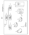
- FIG. 1 shows an airport management and management system 1 according to the present invention, from a boarding / exiting port for vehicles such as buses and taxis of airport facilities to a boarding procedure gate in a passenger terminal, security.
- a plurality of autonomous mobile robots 2 are arranged so as to freely move on each floor up to the inspection site and the boarding gate.
- Power supply stations 3 are installed at predetermined locations in airport facilities and passenger terminals, and each autonomous mobile robot 2 automatically connects without human intervention by detecting the remaining battery level and connecting as necessary. The battery can be charged or replaced.
- the power supply mobile robot 4 equipped with a plurality of drive batteries 4A is arranged so as to be freely movable in the facility, and the battery is automatically replaced when positioned close to each autonomous mobile robot 2.
- the relay function of the power supply station 3 is achieved.
- a plurality of imaging cameras 5 are installed at all locations where security management of airport facilities and passenger terminals is necessary, and video data based on the imaging results of all the imaging cameras 5 is obtained. It is designed to be stored and monitored remotely.
- a plurality of air conditioners (air conditioners) 6 for air conditioning and air purification in the passenger terminal are arranged at predetermined positions, respectively.
- the air cleanliness is managed.
- the plurality of photographing cameras 5, the plurality of air conditioners 6, and the plurality of lighting devices 7 are all managed and controlled collectively by the facility control unit 8 that controls the entire airport management and operation system 1. Has been made.
- the facility control unit 8 exchanges various information with each autonomous mobile robot 2 via wireless communication so as to perform a cooperation function between the airport management operation system 1 and each autonomous mobile robot 2. Has been made.
- the facility control unit 8 manages the power supply station 3 and the power supply mobile robot 4, and controls the charging process for the power supply station 3, guidance movement of the power supply mobile robot 4, and automatic battery replacement. Has been made.
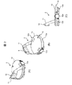
- Autonomous mobile robot 2 is a two-wheel drive type mobile body that can autonomously run in response to an autonomous or external operation, as shown in FIGS. 2 (A) to 2 (C). Is provided with a substantially disc-shaped travel base portion 10 attached so as to have a diameter, and a substantially U-shaped sensor holding portion 11 planted from an upper portion of the plane.
- the traveling base unit 10 is provided at the lower part of the main body, and is provided with a pair of drive wheels 12a and 12b provided at the left and right of the center position in the front-rear direction, and is swingable according to the traveling of the autonomous mobile robot 2 respectively.
- a front caster 13a and a rear caster 13b are provided.
- the left and right drive wheels 12a and 12b are respectively rotated and driven independently by drive motors 14a and 14b.
- the drive wheels 12a and 12b are moved forward and backward by forward rotation or reverse rotation of the drive wheels 12a and 12b. Drive forward or left by giving a difference.
- the autonomous mobile robot 2 spins, that is, changes its direction at that position, by driving the drive wheels 12a and 12b to rotate in opposite directions.
- a laser range sensor 15 that detects obstacles in the diagonally forward direction and the left-right direction is provided at a position in front of the front caster 13a in the traveling base unit 10. Further, an RGB-D sensor 16 and a 3D distance image sensor 17 capable of three-dimensional scanning are provided at the upper center of the sensor holding unit 11.
- the laser range sensor 15 irradiates an object (obstacle) viewed from the installation position, receives the reflected light, and calculates the distance.
- object obstacle
- fan-shaped distance information on a plane can be obtained in a range of a maximum of 30 m and an angle of 240 degrees.
- the RGB-D sensor 16 has a depth sensor that can measure the distance to the object (obstacle) viewed from the camera, and can perform a three-dimensional scan of the object.
- This depth sensor is composed of an infrared sensor, which captures an object in a state where a single pattern of structured light is projected onto the object, and calculates the depth of each point on the image by triangulation using the parameters.
- the RGB-D sensor 16 when Kinect (trade name of Microsoft Corporation) is applied as the RGB-D sensor 16, for example, a horizontal field of view of 57 degrees, a vertical field of view of 43 degrees, and a sensor range of 1.2 m to 3.5 m can be photographed.
- the RGB image is 640 ⁇ 480 and the depth image is 320 ⁇ 240 pixels, both of which can be acquired at 30 frames / second.
- the reason why the RGB-D sensor 16 is installed at the upper center of the sensor holding part 11 is that a vertical visual field cannot be secured in the traveling base part that is almost close to the floor surface, and the height is 0.6 m to 1.8 m from the floor surface. Securement is necessary.
- the 3D distance image sensor 17 irradiates the LED pulse, measures the arrival time of the reflected light from the object in units of pixels, and superimposes the acquired image information, thereby calculating the distance information to the object in units of pixels. To do.
- the 3D distance image sensor 17 has a detection capability with higher accuracy than the RGB-D sensor 16 described above, and has a wider viewing angle than the laser range sensor 15, and thus is required as a complementary sensor for outdoor use. For example, when Pixel Soleil (trade name of Nippon Signal Co., Ltd.) is applied as the 3D distance image sensor 17, a horizontal field of view of 72 degrees, a vertical field of view of 72 degrees, and a sensor range of 0.3 m to 4.0 m should be photographed. Is possible.
- FIG. 3 is a configuration diagram of the overall control unit 20 mounted on the autonomous mobile robot 2.
- the overall control unit 20 is mainly composed of a microcomputer, and includes a travel control unit 11 that controls the entire system, a target travel route storage unit 12 that stores travel route information, and an operation control unit 13 that controls the drive system.
- the travel control unit 11 receives the travel route information from the target travel route storage unit 12 that stores preset travel route information and the detection signals from the laser range sensor 15, the RGB-D sensor 16, and the 3D distance image sensor 17. Based on the self-position estimation and the construction of the environment map described later, the suitability of the travel route and the necessity for change are determined, and the presence or absence of a travel obstacle is determined.
- the autonomous mobile robot 2 on the floor of the passenger terminal travels following the user, it is determined whether or not it touches a traveling obstacle such as immediately before a wall surface or a staircase.
- the direction of travel is changed to the person's following direction.
- the travel control unit 11 sends the determined travel route information to the operation control unit 13, and the operation control unit 13 controls the left and right motor drivers 24a and 24b according to the travel route information, and the drive motors 14a and 14b. Control the rotation.
- the autonomous mobile robot 2 automatically creates an environment map of a target area where a user or worker in the airport facility and passenger terminal can walk using the above-described SLAM technology.
- the autonomous mobile robot 2 moves the local map on the grid divided by the two-dimensional grid based on the distance information and the angle information with respect to the object obtained from the laser range sensor 15 and the 3D distance image sensor 17 as the moving environment.
- An environment map representing the entire desired target area is created.
- the travel amount of the own machine is calculated, and the next location map and the current time are calculated.
- the self-position is estimated from the matching with the environmental map created in the previous section and the traveling amount of the aircraft.
- the autonomous mobile robot 2 includes a communication unit 25 that performs wireless communication.
- the autonomous mobile robot 2 transmits the above-described environmental map data in accordance with the control of the overall control unit 20, and the facility overall control unit 8 ( Various control data are received from FIG.
- a temperature / humidity sensor 30 is mounted at the upper center of the sensor holding unit 11 of the autonomous mobile robot 2, and the temperature and humidity of the surrounding environment are set to a predetermined height position (a height position corresponding to an adult's waist). ) To measure.
- the autonomous mobile robot 2 is equipped with an illuminance sensor 31 made of a photo IC having a spectral sensitivity characteristic close to human visual sensitivity, and measures the illumination level of the surrounding environment.
- the autonomous mobile robot 2 is equipped with a microorganism sensor 32 using a heating fluorescence enhancement method, and measures the amount of microorganisms such as bacteria and fungi floating in the air in a relatively short time. Yes.
- a microorganism sensor 32 using a heating fluorescence enhancement method, and measures the amount of microorganisms such as bacteria and fungi floating in the air in a relatively short time.
- the microorganism measurement time can be as short as about 10 minutes.
- an infrared thermography 33 is mounted on the center of the sensor holding unit 11 of the autonomous mobile robot 2 to grasp the relationship between the environmental temperature and the body surface temperature of the user, and a user having a body temperature of 38 degrees or more. An estimation of the skin temperature is made.
- a load sensor 34 is mounted on the traveling base unit 10 of the autonomous mobile robot 2 so as to measure the load of the baggage placed on the upper surface of the base unit 10.
- the autonomous mobile robot 2 has two relatively large-capacity driving batteries 16 (16A, 16B) made up of secondary batteries or capacitors, and is used as a power supply source that can be switched in parallel. Has been made. These driving batteries 16 are configured as cartridges that can be detachably loaded.
- the external power supply station 3 When the autonomous mobile robot 2 is on standby and determines that the remaining charge amount of any one of the drive batteries 16A and 16B is equal to or less than a predetermined amount until the next scheduled operation time, the external power supply station 3 (see FIG. It moves to 1) and conducts electricity with an internal commercial power supply via the power supply station 3 and charges it in a non-contact manner.
- the autonomous mobile robot 2 of the present invention includes a communication unit 25 (FIG. 3) for a beacon that adopts a communication standard of BLE (Bluetooth (registered trademark) Low Energy). And receiving radio signals transmitted from a beacon terminal (not shown) worn by the user to be serviced, and accurately tracking the presence and location (access point) of the user It is made to do.
- BLE Bluetooth (registered trademark) Low Energy
- This beacon terminal is preferably lightweight, compact, and low power consumption in consideration of the convenience of the user.
- thin-film solar cells can be used to temporarily stop power supply monitoring, and maintenance such as battery replacement is not required due to power supply control technology that can be flexibly deformed.
- a lightweight one is particularly desirable.
- a predetermined area for example, a toilet, a lounge, a smoking room, etc.
- an entry prohibited area for the autonomous mobile robot 2 at the passenger terminal in the airport, and the autonomous mobile robot 2 uses SLAM technology. It is made to memorize
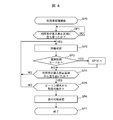
- FIG. 4 shows a processing procedure for the recognition function of the corresponding user by the autonomous mobile robot 2.
- the autonomous mobile robot 2 follows the user (SP0), determines whether or not the user has entered (stopped in) the entry prohibited area (SP1), and has recognized that the user has entered the entry prohibited area. Then, the autonomous mobile robot 2 itself is set in a standby state (SP2).
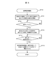
- the autonomous mobile robot 2 determines whether or not it is in the remote monitoring mode (FIG. 5) by the airport management and management system 1 (SP3). Proceed to the processing procedure (SP10).
- the autonomous mobile robot 2 rotates or swings so as to monitor all directions centering on the standby position, while maintaining a predetermined distance (for example, a radius of 50 cm). Detection of an object approaching () is started (SP11). When the autonomous mobile robot 2 detects an object that enters within the predetermined distance (SP12), the autonomous mobile robot 2 issues a warning by one or both of sound and light, and starts recording video and audio toward the object ( SP13).
- a predetermined distance for example, a radius of 50 cm.
- the autonomous mobile robot 2 determines that the situation is a further emergency. (SP14), a radio signal representing an emergency state is transmitted to the facility control unit 8.
- the facility control unit 8 When the facility control unit 8 receives a radio signal from the autonomous mobile robot 2, it recognizes the position of the autonomous mobile robot 2 in the airport facility and can photograph the autonomous mobile robot 2 so that it is centered on the subject. Photographing is performed using at least one photographing camera 5 (SP15).
- the autonomous mobile robot 2 returns to the processing procedure (SP4) shown in FIG. 4 and stops the warning by sound or light when it detects that the object has moved out of the predetermined distance, and the video and audio being recorded. The recording operation is also stopped.
- the autonomous mobile robot 2 recognizes that the user leaves the prohibited entry area, and at the time when the wireless communication from the beacon terminal possessed by the user can be received (SP5), the autonomous mobile robot 2 It follows the user again to make it ready for travel (SP6). At that time, the autonomous mobile robot 2 stops the rotation or swing for monitoring and ends the detection of the object. Thereafter, when the user returns into the passage and starts moving, the autonomous mobile robot 2 also moves following (SP7).
- an imaging camera and a sound collecting microphone are mounted on the center upper portion of the sensor holding unit 11 of the autonomous mobile robot 2, and by collecting sound simultaneously with acquiring an image of the surrounding environment. When a trouble occurs in the surroundings, it is recorded. Furthermore, the efficiency of remote monitoring (enhanced security) can be remarkably improved in conjunction with a plurality of imaging cameras 5 used for remote monitoring of the airport management and operation system 1.
- the autonomous mobile robot 2 determines the presence or absence of an emergency based on the user's utterance content acquired using a photographing camera and a sound collection microphone, or based on the recorded content of video and audio, and communicates as necessary. By sending the information to the facility control unit 8 via the department, an emergency contact is made to the airport staff.
- the external power supply station 3 (FIG. 1) is installed at a plurality of predetermined positions in the airport facility, When the autonomous mobile robot 2 is positioned using a commercial power source as a supply source, it is possible to supply power to the drive battery 16 in a contact or non-contact manner.
- the autonomous mobile robot 2 does not stop at the power supply station 3 directly, and the power supply mobile robot 4 equipped with a plurality of drive batteries 4A moves to the autonomous mobile robot 2 that requested charging.
- the drive battery 4A is replaced.
- the mobile robot 4 for power supply has the same structure as the above-described autonomous mobile robot 2 and the drive system, and is a cartridge type drive battery 4A having the same configuration as the drive battery 16 attached to the autonomous mobile robot 2. Are loaded in a plurality (for example, eight), and can be selectively attached and detached according to drive control of a mechanism system (not shown).
- the power supply mobile robot 4 is positioned in advance at the power supply station 3 and is prepared by charging the drive battery 4A via the power supply station 3 in contact or non-contact with a commercial power supply.
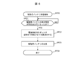
- FIG. 6 shows a processing procedure (SP20) of the mobile battery charging function by cooperation of the autonomous mobile robot 2 and the power supply robot 4.
- SP21 a processing procedure of the mobile battery charging function by cooperation of the autonomous mobile robot 2 and the power supply robot 4.
- the facility control unit 8 receives a radio signal transmitted from the autonomous mobile robot 2 and indicating that the remaining charge amount of the drive battery 16 has become equal to or less than a predetermined amount (SP21)
- the facility overall control unit 8 is placed in the vicinity of the autonomous mobile robot 2.
- the power supply mobile robot 4 is moved and positioned (SP22).
- the power supply mobile robot 4 takes out the drive battery 16 attached to the autonomous mobile robot 2, and uses one of the drive batteries 4 ⁇ / b> A attached to the power supply mobile robot 4.
- Select and exchange SP23.
- the power supply mobile robot 4 preferentially selects the drive battery 4A having the largest remaining charge amount as an object to be replaced with the autonomous mobile robot 2. This is effective in that the troublesomeness that must be rushed again can be avoided when the drive battery with a small remaining charge is replaced.
- the autonomous mobile robot 2 manages the remaining power of the built-in driving battery 16 and, when the remaining power becomes a predetermined value or less, the other driving according to the current activity state. It is determined whether to switch to the battery 16 (16A or 16B), proceed to the nearest power supply station 3, or call the power supply mobile robot 4 via wireless communication.
- the autonomous mobile robot 2 can return to the original state in a relatively short time by simply replacing the driving battery 16. Thus, it is possible to avoid a significant time loss such as returning to the charging operation.
- the facility supervising control unit 8 determines the normal location of the power supply mobile robot 4 in the airport facility not only near the power supply station 3 but also the operating status of the plurality of autonomous mobile robots 2. You may make it designate suitably the place which can rush efficiently.
- the power supply mobile robot 4 since the power supply mobile robot 4 includes a plurality of drive batteries 4A, it can be used as an emergency power source in an emergency. That is, a plug receptacle having the same standard as a commercial power plug receptacle (insertion port) is provided at a predetermined position of the power supply mobile robot 4, and the plug receptacle is electrically connected to a plurality of built-in driving batteries. Thus, power can be supplied in the same manner as a commercial power supply by inserting plugs of various general-purpose devices into plug receptacles provided at predetermined portions.
- the autonomous mobile robot 2 is equipped with an information input device (not shown) for use as a guide display for the user or a map display for the worker as required. You may do it.
- This information input device has a touch panel display disposed on the front surface of the main body, and a mechanism necessary for various information processing, such as a CPU, a graphic processor unit, a sound processor, and a memory, is built in along with a battery.
- the display is composed of a liquid crystal panel or an organic EL (Electric Luminescence) panel, and the upper surface is covered with a touch panel of, for example, a resistive film type or a capacitive coupling type.
- the information input device includes a communication unit such as an infrared port and a wireless LAN for communicating with an autonomous mobile robot and other external devices.
- the display displays menu screens, icons and other screens necessary for user operation input, and environmental map images resulting from information processing, depending on the function. Further, a GUI (Graphical User Interface) is displayed on the screen for the user to input an operation. The user performs an operation input to the information input device by touching the touch panel with a finger or sliding the finger so as to operate the GUI.
- GUI Graphic User Interface
- the autonomous mobile robot 2 has a laser pointer or a projector (both not shown) mounted on the traveling base unit 10 or the sensor holding unit 11, and a mark (for example, a traveling direction) on the floor surface about 1 m ahead when traveling. By irradiating light with an arrow or the like, surrounding humans can visually confirm the traveling direction of the autonomous mobile robot 2.
- the autonomous mobile robot 2 can be applied as an automatic cleaning robot by mounting an external cleaning unit (not shown). Specifically, the cleaning unit is placed on and integrated with the upper surface of the traveling base unit 10 while being engaged with the sensor holding unit 11 of the autonomous mobile robot 2, so that the entire unit is a substantially columnar autonomous mobile cleaning type. As a robot, both functions of conveyance and cleaning can be utilized.
- the autonomous mobile robot 2 is loaded with an AED (automated external defibrillator), and after moving to the relevant user in an emergency (such as finding a user lying on the floor) It is designed to emit sounds and lights to convey emergency situations to the surroundings.
- AED automated external defibrillator
- a flame retardant and tough material polypropylene, polyester,
- the luggage or the like is covered with an anti-theft net made of nylon (for example, 18 mm or 25 mm).
- An electronic or mechanical lock is attached to the end of the anti-theft net with the traveling base unit 10, and only the user can use the beacon terminal, dedicated key, dial input, etc. possessed by the user or operator. Can be unlocked.
- the autonomous mobile robot 2 starts traveling following the user.
- the autonomous mobile robot 2 travels following the user, and keeps the distance between the user and the check-in counter of the passenger terminal within the predetermined distance from the passenger entrance to the passenger terminal, and Travel with care so as not to interfere with other users' walking.
- the autonomous mobile robot 2 responds to the air ticket by reading the image of the air ticket held by the user (including the barcode) and obtaining information from the management system in the airport via the radio unit. It is also possible to specify a check-in counter and guide it.
- the user should take the autonomous mobile robot 2 along with the baggage to the check-in counter. It is also possible to get off at a place where the user wishes to stop by the route designation by the touch panel using the information input device, and the autonomous mobile robot 2 always moves so as to be in the vicinity of the user.
- the user can also follow the back of the autonomous mobile robot 2.
- the autonomous mobile robot 2 is also stopped or stands by according to the user.
- the autonomous mobile robot 2 transmits the load amount of the baggage placed on the traveling base unit 10 to the input terminal of the counter clerk. Display numerical values. If the user puts only the consignment baggage (for in-flight custody) baggage except the carry-on baggage on the travel base 10, the passenger can check whether the baggage is allowed before placing it on the belt conveyor for load measurement. It is possible to determine whether or not.
- the autonomous mobile robot 2 measures the skin temperature of the user's face using the infrared thermography 33 when the user is in the passenger terminal, and determines whether the temperature is 38 degrees or more. As a result, if the body temperature is 38 degrees or more, it is determined that the patient is in poor health, and the user is notified by voice, and at the same time, data indicating that fact is transmitted to the airport staff.
- the autonomous mobile robot 2 starts when the user starts walking while the user places his / her carry-on baggage on the travel base 10. Follow the user and start running.
- the autonomous mobile robot 2 travels following the user, and keeps the distance between the user and the user within a predetermined distance between the check-in counter and the security checkpoint, and also allows other users to walk. Drive with care not to get in the way.
- the autonomous mobile robot 2 When the autonomous mobile robot 2 arrives at the security checkpoint, the autonomous mobile robot 2 detects waiting states of users at a plurality of entrances, and proceeds by selecting the entrance with the least number of people waiting. Thereafter, when the autonomous mobile robot 2 moves away from the user or the user gets on the traveling base unit 10 together with the luggage, the autonomous mobile robot 2 is arranged behind the previous user and sets a predetermined interval so as not to collide. Keep going.
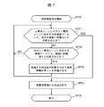
- the autonomous mobile robot 2 and the user are separately inspected at the security checkpoint, and the mobile robot 2 and the corresponding beacon terminal are used. Only when both persons are judged to have no problems in the inspection, they can pass through the security inspection area.
- the user confirms that he / she owns his / her beacon terminal and confirms that his / her luggage has been placed on the traveling base unit 10 of the autonomous mobile robot 2.
- FIG. 7 shows the processing procedure (SP30) of the security inspection support function.
- the autonomous mobile robot 2 is removed from the robot-dedicated lane and transferred to a predetermined waiting place, and the corresponding user arrives. (SP33).
- the autonomous mobile robot 2 After the explanation by the user to the inspector is completed, the autonomous mobile robot 2 returns to the original robot lane, passes through the inspection gate again, and is inspected (SP31).
- the user and the autonomous mobile robot 2 pass through the inspection gates without any problem, and then exit the security checkpoint (SP35), and the autonomous mobile robot 2 approaches the user who owns the corresponding beacon terminal. Wait in a state where you can follow.
- the user and the autonomous mobile robot 2 divide the inspection gate and receive the inspection separately, so that the user can reach the inspection gate while holding baggage as in the past.
- the burden of lining up can be reduced.
- users can face the inspection gate with a margin without being aware of baggage, and even if the baggage arrives later, it is only necessary to wait behind the inspection gate, so the psychological burden that is in order It is possible to reduce stress because there is no point.
- the autonomous mobile robot 2 From the security checkpoint to the boarding gate The autonomous mobile robot 2 walks when the user who has passed the security checkpoint places the carry-on baggage on the travel base 10. When it starts, it follows the user and starts running.
- the autonomous mobile robot 2 travels following the user, and keeps the distance from the user within a predetermined distance between the security checkpoint and the waiting lobby in front of the boarding gate, and other users. Travel with care so as not to interfere with walking.
- the autonomous mobile robot 2 responds to the air ticket by reading the image of the air ticket held by the user (including the barcode) and obtaining information from the airport management system 1 via the radio unit. It is also possible to specify the boarding gate to be guided and guide it.
- the user should be transported to the boarding gate by riding the autonomous mobile robot 2 together with the luggage. It is also possible to get off at a place where it is desired to stop by the route designation by the touch panel using the information input device described above, and the autonomous mobile robot 2 always moves so as to be in the vicinity of the user.
- the user can also follow the back of the autonomous mobile robot 2.
- the autonomous mobile robot 2 is also stopped or stands by according to the user.
- the autonomous mobile robot 2 sets the beacon terminal possessed by the worker to the on state when the beacon terminal is on. After the load is placed on the traveling base unit 10 of the autonomous mobile robot 2, when the worker starts walking, the autonomous mobile robot 2 starts traveling following the worker.
- the autonomous mobile robot 2 travels following the worker, and travels around a predetermined article supply destination (such as a vending machine or a shop) sequentially from the article storage location in the airport facility, and sets the distance interval with the worker. Travel while keeping within a predetermined distance and taking into consideration that it does not interfere with the walking of ordinary users.
- a predetermined article supply destination such as a vending machine or a shop
- a wearable movement assist device when used, it is attached to the back side of the operator's lumbar region by a cuff, and when the operator holds a heavy object, the stress load applied to the operator's lumbar vertebra and lumbar disc is analyzed. Has a function to reduce the burden on the device.
- a beacon terminal is built in the body of the wearable movement assist device, and the autonomous mobile robot 2 accurately grasps the presence and position (access point) of the worker from the radio signal transmitted from the beacon terminal. It is made to track.
- the autonomous mobile robot 2 travels following the worker wearing this wearable motion assist device, and when it recognizes an operation or utterance by the worker, it pauses at that time.
- the autonomous mobile robot 2 does not obstruct the walking of the general user toward the next stop position without following the worker. Travel with consideration.
- the autonomous mobile robot 2 rotates and moves so that the sensor holding unit 11 is not positioned in front of the operator, and the load loaded on the traveling base unit 10 is obstructed by the protrusion of the sensor holding unit 11.
- the position is controlled so that it does not become.
- the autonomous mobile robot 2 when the autonomous mobile robot 2 is stopped at a position that hinders the work of the worker, such as in front of the vending machine, the position of the autonomous mobile robot 2 is not disturbed by about 1 m according to the utterance or operation of the worker. Move back and forth and left and right.
- the autonomous mobile robot 2 removes the manual cart from the airport facility or passenger terminal after completing the transport support for the user and the work support for the worker. By collecting and towing it, it is transported to a predetermined stacking position such as a security checkpoint.
- the autonomous mobile robot determines whether or not the load is placed on the manual luggage cart, and determines that the baggage is to be collected only when no load or the like is placed.
- the temperature / humidity sensor 30 mounted on the autonomous mobile robot 2 by setting the temperature / humidity sensor 30 mounted on the autonomous mobile robot 2 to a predetermined height from the ground, it is possible to detect the sensory temperature / humidity in real time at a location close to human sensing temperature. Is possible.
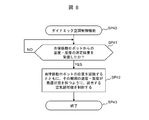
- FIG. 8 shows the processing procedure (SP40) of the dynamic air conditioning control function.
- SP40 processing procedure of the dynamic air conditioning control function.
- the facility control unit 8 of the air conditioning management and management system 1 receives the temperature / humidity measurement results from one or a plurality of autonomous mobile robots 2 (SP41), While recognizing the position, each corresponding air conditioner 6 is controlled so that the ambient temperature and humidity in the vicinity thereof are kept in an optimum state (SP42).
- each user's comfort temperature / humidity information is collected in real time from a plurality of autonomous mobile robots 2, and dynamic air conditioning control is performed, so that the comfort of each user can be improved. It is possible to always maintain a stable situation.
- the illuminance sensor 31 mounted on the autonomous mobile robot 2 is set at a height position that is a predetermined height from the ground, so that the sensation illuminance can be detected in real time at a location close to human sensed illuminance. Is possible.
- the air conditioning management and management system 1 collects the illuminance information of each user from a plurality of autonomous mobile robots 2 in real time, and adjusts the daytime indoor light intake and brightness balance for each predetermined area in real time. can do.
- the microorganism sensor 32 is mounted on the autonomous mobile robot, it is possible to measure the amount of microorganisms such as bacteria and fungi floating in the air in a relatively short time.
- the air-conditioning management and operation system 1 can collect microbial measurement information from the plurality of autonomous mobile robots 2 in real time and detect the cleanliness of air for each predetermined area in real time.
- the autonomous mobile robot 2 is equipped with an external cleaning unit during the time when there is no request for assistance from the user or worker, and the passenger terminal Clean the inside floor.
- the floor surface route in the passenger terminal to be cleaned may be displayed in advance on the touch panel of the information input device so that the operator can specify the travel route for each area.
- the autonomous mobile robot 2 can operate 24 hours a day if the battery is continuously replaced, and the work efficiency can be greatly improved.
- the nearest autonomous mobile robot 2 can capture the situation in real time by shooting the specific location as long as it does not bother users and workers. It becomes.
- the facility control unit 8 receives an audio signal representing the sound collection content of the sound collection microphone from the autonomous mobile robot 2, and determines that it is a necessary situation based on the sound collection content. In this case, if only the position of the autonomous mobile robot 2 in the facility is recognized, remote monitoring with only voice becomes possible. In addition to this, if the autonomous mobile robot 2 is photographed using at least one photographing camera 5 that can photograph the autonomous mobile robot 2 so as to be the subject center in conjunction with a plurality of photographing cameras 5, the efficiency of remote monitoring (enhanced security) ) Can be significantly improved.
- the determination as to whether or not this is a necessary situation is made by the facility control unit 8 by analyzing the sound collection content based on the audio signal. That is, the facility control unit 8 calculates the content ratio (amplitude ratio) of each frequency component in the analysis section based on the frequency spectrum obtained by analyzing the audio signal, and the specific frequency spectrum has a constant intensity. The voice including the characteristics of vowels and consonants is recognized depending on whether or not it exists in proportion or more. The facility supervision control unit 8 then collects the content of the words and utterances that express the emotions such as screams, screams, and bangs, as well as impact sounds such as plosives and explosion sounds, etc. It is determined whether or not the sound is predicted to cause a problem.
- the airport management and management system 1 when it is determined that the collected sound contents based on the audio signals received from the plurality of autonomous mobile robots 2 are from the same sound source, the sound source position is estimated, and the estimated sound source position is centered on the subject. Photographing is performed using at least one or more photographing cameras 5 capable of photographing. According to the in-facility management management system 1, it is possible to further improve the efficiency of remote monitoring by instantaneously identifying and shooting the position of the sound source that caused the necessary situation.
- a general sound source localization method that is, a method of using a plurality of microphones and identifying the direction of the sound source from the phase difference or intensity difference of the sound source data input to each
- FBS FrequencyBBand Selection
- DSBF DelayedDSSum : Beam Forming
- the flatness of the difference between the spatial spectrum waveform of the sound pressure distribution observed in all directions and the spatial spectrum waveform of the point sound source created in advance is obtained, and it is determined whether or not it is within a predetermined threshold.
- a point sound source detection method may be used.
- the autonomous mobile robot 2 that freely moves in the facility can accurately grasp the presence and position (access point) of the user. In addition to being able to track, it is possible to always follow the user in the facility without losing sight of the user by placing the user in a standby state while entering the prohibited entry area.
- At least one autonomous mobile robot 2 that freely moves in the facility is disposed, and the facility overall control unit 8 that transmits and receives various information to and from the autonomous mobile robot 2 through wireless communication is provided.
- the efficiency of remote monitoring (enhancement of security) can be remarkably improved in conjunction with a plurality of imaging cameras 5 used for remote monitoring. .
- the autonomous mobile robot 2 is in real time at a place near the human sensed temperature while traveling.
- the autonomous mobile robot 2 is in real time at a place near the human sensed temperature while traveling.
- the inspection gate (first inspection gate) corresponding to the robot-dedicated lane and the inspection gate (second inspection gate) corresponding to the human-dedicated lane are divided. By separately inspecting each other, it is possible to reduce the burden (stress) that is lined up until the user reaches the inspection gate while holding the baggage.
- the driving battery 16 is powered. It is possible to return to the original state in a relatively short time by simply replacing the battery for driving (second battery) 4A held by the supply mobile robot 4, and return to the charging work as in the past. It is possible to avoid a large loss in advance.
Landscapes
- Engineering & Computer Science (AREA)
- Aviation & Aerospace Engineering (AREA)
- Radar, Positioning & Navigation (AREA)
- Remote Sensing (AREA)
- Physics & Mathematics (AREA)
- General Physics & Mathematics (AREA)
- Automation & Control Theory (AREA)
- Power Engineering (AREA)
- Transportation (AREA)
- Mechanical Engineering (AREA)
- Control Of Position, Course, Altitude, Or Attitude Of Moving Bodies (AREA)
Abstract
Description
図1は本発明の空港内管理運営システム1を示し、空港内施設のバスやタクシーなどの乗り物の乗降車口から旅客ターミナル内の搭乗手続口、保安検査場および搭乗口までの各フロアを、複数の自律移動ロボット2が自由に移動するように配置されている。
自律移動ロボット2は、図2(A)から(C)に示すように、自律的又は外部操作に応じて自走可能な二輪駆動型移動体であり、駆動二輪が直径をなすように取り付けられた略円盤状の走行ベース部10と、その平面上部から植立した略コ字状のセンサ保持部11とを備える。
図3は、自律移動ロボット2に搭載される統括制御部20の構成図である。統括制御部20はマイクロコンピュータを主体として構成され、全体の制御を司る走行制御部11、走行経路情報を記憶する目標走行経路記憶部12、駆動系を制御する作動制御部13を備える。
本発明の自律移動ロボット2は、BLE(Bluetooth(登録商標) Low Energy)の通信規格を採用したビーコン(Beacon)用の通信部25(図3)を有し、サービス対象となる利用者が身につけているビーコン端末(図示せず)から発信される無線信号を受信して、当該利用者の存在や位置(アクセスポイント)を正確に把握しながら追尾するようになされている。
本発明の空用内管理運営システム1においては、外部の電源供給ステーション3(図1)は、空港施設内の複数の所定位置に設置され、商用電源を供給源として自律移動ロボット2が位置決めされたときに、接触または非接触で駆動用バッテリ16に給電することが可能である。
自律移動ロボット2は、利用者への案内表示や作業者への地図表示などに役立てるための情報入力装置(図示せず)を必要に応じて取り付けるようにしても良い。
(7-1)自律移動ロボットを用いた利用者向け機能
(7-1-1)空港内施設(乗降車口)から旅客ターミナル内のチェックインカウンタまで
自律移動ロボット2は、利用者の呼出し又は事前予約に応じて空港内施設の乗降車口に待機しておき、利用者がビーコン端末をオン状態にすると、追従可能状態にセットする。
自律移動ロボット2は、利用者が機内持ち込み用の手荷物を走行ベース部10に載置した状態で、利用者が歩行し始めると、当該利用者の後に追従して走行を開始する。
自律移動ロボット2は、保安検査場を通過した利用者が機内持ち込み用の手荷物を走行ベース部10に載置した状態で、利用者が歩行し始めると、当該利用者の後に追従して走行を開始する。
(7-2-1)物品販売の補充のための搬送サポート
自律移動ロボット2は、空港内の自動販売機や売店などの物品販売の補充のための搬送ロボットとしての役割を果たす。
近年、生体信号に基づく随意的および自律的なフィードバック制御を行うことが可能な装着式動作補助装置が提案されており(意願2014-5841、意願2014-5842、意願2014-5843、意匠登録第1515524号など)、作業者が荷揚げ荷下ろし作業における腰部負荷を低減し得るようになされている。
自律移動ロボット2は、利用者の搬送サポートや作業者の作業支援を終了後、空港施設内や旅客ターミナル内に放置してある手動式荷物カートを回収して牽引することにより、保安検査場など所定の集積位置まで搬送する。
(7-3-1)ダイナミック空調制御機能
空港内管理運営システム1において、旅客ターミナル内の空調管理を一括して行っているが、自律移動ロボット2が走行中に、大勢の利用者が集まる場所のように特定箇所で温度上昇して利用者に不快感を与える状況を判断すると、当該特定箇所のみ冷風が到達するように空調制御する。
空港内管理運営システム1において、空港施設内や旅客ターミナル内の照明は日中は太陽光を積極的に活用して、比較的省エネルギーを図っているが、曇り時々晴れのように日中の日差しが不安定となる場合は、複数の照明機器の単なる一括した照度調整では不十分である。
空港内管理運営システム1において、空港施設内や旅客ターミナル内の清潔度を複数の自律移動ロボット2を用いてリアルタイムかつピンポイントで検知することが可能である。
空港内管理運営システム1において、自律移動ロボット2は、利用者や作業者からの支援要求がない時間帯で、外部の清掃ユニットを搭載して、旅客ターミナル内の床面の清掃を行う。
空港内管理運営システム1において、複数の自律移動ロボット2が空港内施設内及び旅客ターミナル内を撮影カメラ及び集音マイクを稼働させながら移動することにより、施設内の固定された撮影カメラ5だけでは把握できない周囲環境の映像音声を取得することができる。
以上のように本実施の形態によれば、施設内を自由に移動する自律移動ロボット2において、利用者の存在や位置(アクセスポイント)を正確に把握しながら追尾することができるとともに、利用者が進入禁止区域に立ち入っている間は待機状態にすることにより、施設内の利用者を見失うことなく常に追従することが可能となる。
本実施の形態においては、自律移動ロボット2を、主として空港内管理運営システム内に適用した場合について述べたが、本発明はこれに限らず、大型ショッピングモールやデパート、総合病院、遊園地等のアミューズメント施設など、その他種々の施設管理運営システムに広く適用することができる。
Claims (15)
- 施設内を自由に移動する自律移動体において、
前記施設内の外部環境に対して自己の位置を推定すると同時に、平面的または立体的な環境地図を作成するSLAM機能部と、
目標対象物に前記自律移動体に固有のビーコン端末を保持しておき、当該ビーコン端末からの無線信号に基づいて前記目標対象物の存在及び位置をリアルタイムで認識する追従認識部と、
前記追従認識部の認識結果に基づいて、前記自律移動体を前記目標対象物の移動に追従して走行させながら、前記SLAM機能部の出力に基づいて、前記自律移動体の走行経路を周囲の物体と接触しないように適宜変更する走行制御部と
を備え、
前記走行制御部は、
前記自律移動体が前記施設内の進入禁止に指定された特定区域に前記目標対象物が立ち入った時点で、前記自律移動体を待機状態とした後、当該特定地域から前記目標対象物が立ち退き、かつ前記ビーコン端末からの無線信号が受信可能となった時点で、前記自律移動体を再度前記目標対象物に追従して走行可能状態にする
ことを特徴とする自律移動体。 - 前記走行制御部は、
前記目標対象物が前記特定区域に立ち入った時点で、前記自律移動体の待機位置を中心に全方位を監視するように回転または揺動しながら、所定距離内に近づく物体の検知を開始し、
前記目標対象物が前記特定区域を立ち退くとともに、前記ビーコン端末からの無線信号が受信可能となった時点で、前記自律移動体の回転または揺動を停止するとともに、前記物体の検知を終了する
ことを特徴とする請求項1に記載の自律移動体。 - 前記走行制御部は、
前記所定距離内に侵入する前記物体を検知したときに、音および光のいずれか一方又は両方による警告を発し、
前記所定距離外に前記物体が離れたことを検知したときに、前記警告を停止する
ことを特徴とする請求項2に記載の自律移動体。 - 前記走行制御部は、
前記所定距離内に侵入する前記物体を検知したときに、当該物体の映像音声を記録し始め、
前記所定距離外に前記物体が離れたことを検知したときに、前記映像音声の記録を停止する
ことを特徴とする請求項2または3のいずれかに記載の自律移動体。 - 施設内を自由に移動する自律移動体が少なくとも1以上配置され、当該自律移動体と無線通信を介して各種情報を送受信する統括制御部を有する施設内管理運営システムにおいて、
前記施設内に設置された複数の撮影カメラを備え、
前記自律移動体は、
前記施設内の外部環境に対して自己の位置を推定すると同時に、平面的または立体的な環境地図を作成するSLAM機能部と、
目標対象物に前記自律移動体に固有のビーコン端末を保持しておき、当該ビーコン端末からの無線信号に基づいて前記目標対象物の存在及び位置をリアルタイムで認識する追従認識部と、
前記追従認識部の認識結果に基づいて、前記自律移動体を前記目標対象物の移動に追従して走行させながら、前記SLAM機能部の出力に基づいて、前記自律移動体の走行経路を周囲の物体と接触しないように適宜変更する走行制御部と
を備え、
前記統括制御部は、
前記自律移動体からの要求を表す無線信号を受信した場合、前記施設内における当該自律移動体の位置を認識するとともに、当該自律移動体を被写体中心となるように撮影可能な少なくとも1以上の前記撮影カメラを用いて撮影する
ことを特徴とする施設内管理運営システム。 - 施設内を自由に移動する自律移動体が少なくとも1以上配置され、当該自律移動体と無線通信を介して各種情報を送受信する統括制御部を有する施設内管理運営システムにおいて、
前記施設内全体の冷暖房を含む空気調和のために設置された複数の空気調和機を備え、
前記自律移動体は、
前記施設内の外部環境に対して自己の位置を推定すると同時に、平面的または立体的な環境地図を作成するSLAM機能部と、
目標対象物に前記自律移動体に固有のビーコン端末を保持しておき、当該ビーコン端末からの無線信号に基づいて前記目標対象物の存在及び位置をリアルタイムで認識する追従認識部と、
前記追従認識部の認識結果に基づいて、前記自律移動体を前記目標対象物の移動に追従して走行させながら、前記SLAM機能部の出力に基づいて、前記自律移動体の走行経路を周囲の物体と接触しないように適宜変更する走行制御部と、
床面から所定高さ位置に搭載され、周囲環境の温度及び湿度を計測するための温度湿度センサと
を備え、
前記統括制御部は、
前記自律移動体から前記温度湿度センサの測定結果を含む無線信号を受信した際、前記施設内における当該自律移動体の位置を認識するとともに、当該自律移動体の周囲の温度及び湿度が最適状態を保つように、対応する各前記空気調和機を制御する
ことを特徴とする施設内管理運営システム。 - 前記自律移動体は、空気中を浮遊する微生物の量を計測する微生物センサをさらに備え、
前記統括制御部は、
前記自律移動体から前記微生物センサの測定結果を含む無線信号を受信した際、前記施設内における当該自律移動体の位置を認識するとともに、当該自律移動体の周囲の空気清浄度が最適状態を保つように、対応する各前記空気調和機を制御する
ことを特徴とする請求項5に記載の施設内管理運営システム。 - 施設内を自由に移動する自律移動体が少なくとも1以上配置され、当該自律移動体と無線通信を介して各種情報を送受信する統括制御部を有する施設内管理運営システムにおいて、
前記自律移動体に載置した荷物の検査を行う第1の検査ゲートと、前記目標対象物の検査を行う第2の検査ゲートとを有する検査区域が施設され、
前記自律移動体は、
前記施設内の外部環境に対して自己の位置を推定すると同時に、平面的または立体的な環境地図を作成するSLAM機能部と、
目標対象物に前記自律移動体に固有のビーコン端末を保持しておき、当該ビーコン端末からの無線信号に基づいて前記目標対象物の存在及び位置をリアルタイムで認識する追従認識部と、
前記追従認識部の認識結果に基づいて、前記自律移動体を前記目標対象物の移動に追従して走行させながら、前記SLAM機能部の出力に基づいて、前記自律移動体の走行経路を周囲の物体と接触しないように適宜変更する走行制御部と、
を備え、
前記統括制御部は、
前記第1及び第2の検査ゲートの両方の検査結果が問題なしと判断された場合のみ、前記目標対象物に対して前記検査区域を退出する許可をし、
前記第1の検査ゲートの検査結果が問題ありと判断された場合は、前記自律移動体を前記目標対象物が到着するまで所定の待機位置で待機させる
ことを特徴とする施設内管理運営システム。 - 施設内を自由に移動する自律移動体が少なくとも1以上配置され、当該自律移動体と無線通信を介して各種情報を送受信する統括制御部を有する施設内管理運営システムにおいて、
前記自律移動体は、
前記施設内の外部環境に対して自己の位置を推定すると同時に、平面的または立体的な環境地図を作成するSLAM機能部と、
前記SLAM機能部の出力に基づいて、前記自律移動体の走行経路を周囲の物体と接触しないように適宜変更する走行制御部と、
周囲環境の音声を集音するための集音マイクと
を備え、
前記統括制御部は、
前記自律移動体から前記集音マイクの集音内容を表す音声信号を受信し、当該集音内容に基づいて必要事態であると判断した場合、前記施設内における当該自律移動体の位置を認識する
ことを特徴とする施設内管理運営システム。 - 前記施設内に設置された複数の撮影カメラをさらに備え、
前記統括制御部は、
位置認識した前記自律移動体を被写体中心となるように撮影可能な少なくとも1以上の前記撮影カメラを用いて撮影する
ことを特徴とする請求項9に記載の施設内管理運営システム。 - 前記統括制御部は、
複数の前記自律移動体からそれぞれ受信した音声信号に基づく集音内容が同一の音源によると判断した場合、当該音源位置を推定し、推定した音源位置を被写体中心となるように撮影可能な少なくとも1以上の前記撮影カメラを用いて撮影する
ことを特徴とする請求項10に記載の施設内管理運営システム。 - 施設内を自由に移動する自律移動体が少なくとも1以上配置され、当該自律移動体と無線通信を介して各種情報を送受信する統括制御部を有する施設内管理運営システムにおいて、
前記自律移動体は、
前記施設内の外部環境に対して自己の位置を推定すると同時に、平面的または立体的な環境地図を作成するSLAM機能部と、
前記SLAM機能部の出力に基づいて、前記自律移動体の走行経路を周囲の物体と接触しないように適宜変更する走行制御部と、
着脱自在に装着され、駆動源としてのカートリッジ式からなる第1バッテリと、
を備え、
前記施設内に設置され、商用電源を供給源とする電源供給ステーションと、
前記施設内に移動自在に配置され、前記第1バッテリと同一構成からなる複数のカートリッジ式の第2バッテリを着脱自在に搭載する電源供給用移動体と、
を備え、
前記統括制御部は、
前記電源供給用移動体を前記電源供給ステーションに到達させた際、当該電源供給ステーションを介して商用電源からの電力を前記各第2バッテリに充電しておき、前記自律移動体から送信される前記第1バッテリの残充電量が所定量以下になったことを表す無線信号を受信すると、当該自律移動体の近傍に前記電源供給用移動体を移動させて位置決めした後、当該自律移動体に装着されている前記第1バッテリを取り出して、当該電源供給用移動体に装着されている複数の前記第2バッテリの一つと交換する
ことを特徴とする施設内管理運営システム。 - 前記電源供給用移動体は、複数の前記第2バッテリのうち最も残充電量が多いものを優先的に交換対象とする
ことを特徴とする請求項12に記載の施設内管理運営システム。 - 前記電源供給ステーションは、商用電源からの電力を、非接触給電にて前記電源供給用移動体に装着されている複数の前記第2バッテリに充電する
ことを特徴とする請求項12に記載の施設内管理運営システム。 - 前記統括制御部は、
複数の前記自律移動体の稼働状況を把握しながら、前記電源供給用移動体の配置箇所を指定する
ことを特徴とする請求項12に記載の施設内管理運営システム。
Priority Applications (2)
| Application Number | Priority Date | Filing Date | Title |
|---|---|---|---|
| JP2017535572A JP6623341B2 (ja) | 2015-08-19 | 2016-08-19 | 施設内管理運営システム |
| SG11201801327QA SG11201801327QA (en) | 2015-08-19 | 2016-08-19 | Autonomous mobile body and on-site operation management system |
Applications Claiming Priority (2)
| Application Number | Priority Date | Filing Date | Title |
|---|---|---|---|
| JP2015-162318 | 2015-08-19 | ||
| JP2015162318 | 2015-08-19 |
Publications (1)
| Publication Number | Publication Date |
|---|---|
| WO2017030188A1 true WO2017030188A1 (ja) | 2017-02-23 |
Family
ID=58050864
Family Applications (1)
| Application Number | Title | Priority Date | Filing Date |
|---|---|---|---|
| PCT/JP2016/074226 Ceased WO2017030188A1 (ja) | 2015-08-19 | 2016-08-19 | 自律移動体および施設内管理運営システム |
Country Status (3)
| Country | Link |
|---|---|
| JP (1) | JP6623341B2 (ja) |
| SG (1) | SG11201801327QA (ja) |
| WO (1) | WO2017030188A1 (ja) |
Cited By (35)
| Publication number | Priority date | Publication date | Assignee | Title |
|---|---|---|---|---|
| WO2018179104A1 (ja) * | 2017-03-28 | 2018-10-04 | 三菱電機株式会社 | 設備管理装置 |
| JP2018160210A (ja) * | 2017-03-24 | 2018-10-11 | 株式会社日立ビルシステム | ロボット制御システム及びロボット |
| TWI640171B (zh) * | 2017-12-27 | 2018-11-01 | 鴻海精密工業股份有限公司 | 移動裝置 |
| KR20190030613A (ko) * | 2017-09-14 | 2019-03-22 | 포테닛 주식회사 | 전기자동차의 배터리 충전 시스템 및 방법 |
| WO2019065317A1 (ja) * | 2017-09-29 | 2019-04-04 | 日本電産株式会社 | 移動体 |
| CN109709947A (zh) * | 2017-10-26 | 2019-05-03 | 株式会社日立大厦系统 | 机器人管理系统 |
| WO2019163044A1 (ja) * | 2018-02-22 | 2019-08-29 | 株式会社Fuji | 部品実装システム |
| WO2019171693A1 (ja) * | 2018-03-08 | 2019-09-12 | ソニー株式会社 | 情報処理装置、情報処理方法、および、プログラム |
| KR102033326B1 (ko) * | 2019-02-01 | 2019-10-17 | (주)에바 | 사용자 주행 제어와 자율주행 기반으로 주행하며 중앙 제어와 관리자 제어에 의해 주행 안전성을 확보한 전기자동차 충전용 전동 카트 |
| KR102033325B1 (ko) * | 2019-02-01 | 2019-10-18 | (주)에바 | 자동 정지되며 반동 및 자극으로 장애물에 대한 알람을 제공하는 전동 카트 |
| WO2020035902A1 (ja) * | 2018-08-14 | 2020-02-20 | 学校法人 千葉工業大学 | 移動ロボット |
| KR102102573B1 (ko) * | 2020-02-03 | 2020-04-20 | 윤대원 | 건물 기계실 내 장비 유지관리 시스템 |
| JP2020086678A (ja) * | 2018-11-19 | 2020-06-04 | 株式会社日建設計総合研究所 | 自律移動ロボット及びデータ計測システム |
| JP2020107116A (ja) * | 2018-12-27 | 2020-07-09 | 株式会社豊田自動織機 | 自律移動体 |
| WO2020159238A1 (ko) * | 2019-02-01 | 2020-08-06 | (주)에바 | 전동 카트 |
| JP2020527266A (ja) * | 2017-07-10 | 2020-09-03 | トラベルメイト ロボティクス, インク.Travelmate Robotics, Inc. | 自律ロボットシステム |
| CN111983706A (zh) * | 2020-08-24 | 2020-11-24 | 北京航星机器制造有限公司 | 一种智能安检系统和安检方法 |
| JP2020189358A (ja) * | 2019-05-21 | 2020-11-26 | 川崎重工業株式会社 | 給電システム及び給電装置 |
| JP2021061721A (ja) * | 2019-10-09 | 2021-04-15 | Dmg森精機株式会社 | 給電装置および給電システム |
| WO2021176585A1 (ja) * | 2020-03-04 | 2021-09-10 | 日本電気株式会社 | 制御装置、監視システム、制御方法、及びコンピュータ読み取り可能な記録媒体 |
| JP2021536064A (ja) * | 2018-09-06 | 2021-12-23 | エルジー エレクトロニクス インコーポレイティドLg Electronics Inc. | 移動ロボット及びその制御方法 |
| CN114104145A (zh) * | 2020-08-27 | 2022-03-01 | 丰田自动车株式会社 | 搬运系统、搬运方法及程序 |
| KR20220078172A (ko) * | 2020-12-03 | 2022-06-10 | 재단법인 경북자동차임베디드연구원 | 비대면 체온측정장치 및 이를 이용한 비대면 체온측정방법 |
| JP2022117117A (ja) * | 2021-01-29 | 2022-08-10 | 株式会社Wds | 情報処理システム、情報処理方法、及び情報処理プログラム |
| WO2022208696A1 (ja) * | 2021-03-30 | 2022-10-06 | 株式会社デンソーテン | 貸出システムおよび貸出方法 |
| CN115432084A (zh) * | 2021-06-04 | 2022-12-06 | 丰田自动车株式会社 | 移动体系统 |
| JP2022187064A (ja) * | 2021-06-07 | 2022-12-19 | 東日本旅客鉄道株式会社 | 利用者の移動支援システム |
| WO2023020269A1 (zh) * | 2021-08-17 | 2023-02-23 | 科沃斯机器人股份有限公司 | 自移动机器人控制方法、装置、设备及可读存储介质 |
| JP2023034963A (ja) * | 2021-08-31 | 2023-03-13 | 株式会社フジタ | 検出システム、検出方法、および情報処理装置 |
| JP2023151177A (ja) * | 2022-03-31 | 2023-10-16 | 本田技研工業株式会社 | 移動体の制御装置、移動体の制御方法、プログラム及び記憶媒体 |
| JP2023151163A (ja) * | 2022-03-31 | 2023-10-16 | 本田技研工業株式会社 | 移動体の制御装置、移動体の制御方法、プログラム及び記憶媒体 |
| US20240190018A1 (en) * | 2022-12-13 | 2024-06-13 | Semes Co., Ltd. | Transfer robot system and the transfer robot system driving method |
| JP2024119981A (ja) * | 2020-09-11 | 2024-09-03 | ローカス ロボティクス コーポレイション | 移動式ロボットを使用した動的な物品収納管理 |
| WO2025069399A1 (ja) * | 2023-09-29 | 2025-04-03 | 本田技研工業株式会社 | 移動体の制御装置、移動体の制御方法、およびプログラム |
| TWI892390B (zh) * | 2023-01-03 | 2025-08-01 | 大陸商北京石頭創新科技有限公司 | 清潔設備控制方法、裝置、電子設備和可讀存儲介質 |
Families Citing this family (1)
| Publication number | Priority date | Publication date | Assignee | Title |
|---|---|---|---|---|
| JP7484758B2 (ja) * | 2021-02-09 | 2024-05-16 | トヨタ自動車株式会社 | ロボット制御システム |
Citations (8)
| Publication number | Priority date | Publication date | Assignee | Title |
|---|---|---|---|---|
| JPS60159305U (ja) * | 1984-03-31 | 1985-10-23 | 清水建設株式会社 | クリ−ンル−ムの環境測定ロボツト |
| JPH10171533A (ja) * | 1996-12-06 | 1998-06-26 | Cosmo Ii C Kk | 自動追尾式飼犬先導車 |
| JP2003295951A (ja) * | 2002-03-29 | 2003-10-17 | Sogo Keibi Hosho Co Ltd | 自律移動体巡回システムおよび自律移動体の位置補正方法 |
| JP2005275899A (ja) * | 2004-03-25 | 2005-10-06 | Funai Electric Co Ltd | 自走式掃除機 |
| JP2008191800A (ja) * | 2007-02-02 | 2008-08-21 | Hitachi Ltd | 先導者追従車両 |
| JP2009157430A (ja) * | 2007-12-25 | 2009-07-16 | Toyota Motor Corp | 座標補正方法、座標補正プログラム、及び自律移動ロボット |
| JP2009295140A (ja) * | 2008-06-04 | 2009-12-17 | National Chiao Tung Univ | 侵入者検知システム及びその方法 |
| JP2010256945A (ja) * | 2009-04-21 | 2010-11-11 | Kanto Auto Works Ltd | バッテリ自動交換・自動充電装置 |
-
2016
- 2016-08-19 JP JP2017535572A patent/JP6623341B2/ja active Active
- 2016-08-19 SG SG11201801327QA patent/SG11201801327QA/en unknown
- 2016-08-19 WO PCT/JP2016/074226 patent/WO2017030188A1/ja not_active Ceased
Patent Citations (8)
| Publication number | Priority date | Publication date | Assignee | Title |
|---|---|---|---|---|
| JPS60159305U (ja) * | 1984-03-31 | 1985-10-23 | 清水建設株式会社 | クリ−ンル−ムの環境測定ロボツト |
| JPH10171533A (ja) * | 1996-12-06 | 1998-06-26 | Cosmo Ii C Kk | 自動追尾式飼犬先導車 |
| JP2003295951A (ja) * | 2002-03-29 | 2003-10-17 | Sogo Keibi Hosho Co Ltd | 自律移動体巡回システムおよび自律移動体の位置補正方法 |
| JP2005275899A (ja) * | 2004-03-25 | 2005-10-06 | Funai Electric Co Ltd | 自走式掃除機 |
| JP2008191800A (ja) * | 2007-02-02 | 2008-08-21 | Hitachi Ltd | 先導者追従車両 |
| JP2009157430A (ja) * | 2007-12-25 | 2009-07-16 | Toyota Motor Corp | 座標補正方法、座標補正プログラム、及び自律移動ロボット |
| JP2009295140A (ja) * | 2008-06-04 | 2009-12-17 | National Chiao Tung Univ | 侵入者検知システム及びその方法 |
| JP2010256945A (ja) * | 2009-04-21 | 2010-11-11 | Kanto Auto Works Ltd | バッテリ自動交換・自動充電装置 |
Cited By (56)
| Publication number | Priority date | Publication date | Assignee | Title |
|---|---|---|---|---|
| JP2018160210A (ja) * | 2017-03-24 | 2018-10-11 | 株式会社日立ビルシステム | ロボット制御システム及びロボット |
| WO2018179104A1 (ja) * | 2017-03-28 | 2018-10-04 | 三菱電機株式会社 | 設備管理装置 |
| JP2020527266A (ja) * | 2017-07-10 | 2020-09-03 | トラベルメイト ロボティクス, インク.Travelmate Robotics, Inc. | 自律ロボットシステム |
| KR101987143B1 (ko) * | 2017-09-14 | 2019-06-10 | 포테닛 주식회사 | 전기자동차의 배터리 충전 시스템 및 방법 |
| KR20190030613A (ko) * | 2017-09-14 | 2019-03-22 | 포테닛 주식회사 | 전기자동차의 배터리 충전 시스템 및 방법 |
| JPWO2019065317A1 (ja) * | 2017-09-29 | 2020-10-22 | 日本電産株式会社 | 移動体 |
| WO2019065317A1 (ja) * | 2017-09-29 | 2019-04-04 | 日本電産株式会社 | 移動体 |
| CN109709947B (zh) * | 2017-10-26 | 2021-11-16 | 株式会社日立大厦系统 | 机器人管理系统 |
| CN109709947A (zh) * | 2017-10-26 | 2019-05-03 | 株式会社日立大厦系统 | 机器人管理系统 |
| TWI640171B (zh) * | 2017-12-27 | 2018-11-01 | 鴻海精密工業股份有限公司 | 移動裝置 |
| WO2019163044A1 (ja) * | 2018-02-22 | 2019-08-29 | 株式会社Fuji | 部品実装システム |
| WO2019171693A1 (ja) * | 2018-03-08 | 2019-09-12 | ソニー株式会社 | 情報処理装置、情報処理方法、および、プログラム |
| US11897360B2 (en) | 2018-03-08 | 2024-02-13 | Sony Corporation | Information processing device, information processing method, and program |
| JPWO2019171693A1 (ja) * | 2018-03-08 | 2021-02-18 | ソニー株式会社 | 情報処理装置、情報処理方法、および、プログラム |
| TWI766410B (zh) * | 2018-08-14 | 2022-06-01 | 日本千葉工業大學 | 移動機器人 |
| JPWO2020035902A1 (ja) * | 2018-08-14 | 2020-08-20 | 学校法人千葉工業大学 | 移動ロボット |
| WO2020035902A1 (ja) * | 2018-08-14 | 2020-02-20 | 学校法人 千葉工業大学 | 移動ロボット |
| US11409306B2 (en) | 2018-08-14 | 2022-08-09 | Chiba Institute Of Technology | Movement robot |
| JP2021536064A (ja) * | 2018-09-06 | 2021-12-23 | エルジー エレクトロニクス インコーポレイティドLg Electronics Inc. | 移動ロボット及びその制御方法 |
| JP2020086678A (ja) * | 2018-11-19 | 2020-06-04 | 株式会社日建設計総合研究所 | 自律移動ロボット及びデータ計測システム |
| JP7325947B2 (ja) | 2018-11-19 | 2023-08-15 | 株式会社日建設計総合研究所 | 自律移動ロボット及びデータ計測システム |
| JP2020107116A (ja) * | 2018-12-27 | 2020-07-09 | 株式会社豊田自動織機 | 自律移動体 |
| KR102033325B1 (ko) * | 2019-02-01 | 2019-10-18 | (주)에바 | 자동 정지되며 반동 및 자극으로 장애물에 대한 알람을 제공하는 전동 카트 |
| KR102033326B1 (ko) * | 2019-02-01 | 2019-10-17 | (주)에바 | 사용자 주행 제어와 자율주행 기반으로 주행하며 중앙 제어와 관리자 제어에 의해 주행 안전성을 확보한 전기자동차 충전용 전동 카트 |
| US12019451B2 (en) | 2019-02-01 | 2024-06-25 | Evar Co., Ltd. | Electric cart |
| WO2020159238A1 (ko) * | 2019-02-01 | 2020-08-06 | (주)에바 | 전동 카트 |
| JP7357873B2 (ja) | 2019-05-21 | 2023-10-10 | 川崎重工業株式会社 | 給電システム及び給電装置 |
| JP2020189358A (ja) * | 2019-05-21 | 2020-11-26 | 川崎重工業株式会社 | 給電システム及び給電装置 |
| US12095265B2 (en) | 2019-05-21 | 2024-09-17 | Kawasaki Jukogyo Kabushiki Kaisha | Power supply system and power supply device |
| JP2021061721A (ja) * | 2019-10-09 | 2021-04-15 | Dmg森精機株式会社 | 給電装置および給電システム |
| KR102102573B1 (ko) * | 2020-02-03 | 2020-04-20 | 윤대원 | 건물 기계실 내 장비 유지관리 시스템 |
| US12592154B2 (en) | 2020-03-04 | 2026-03-31 | Nec Corporation | Control device, monitoring system, control method, and non-transitory computer-readable recording medium |
| JPWO2021176585A1 (ja) * | 2020-03-04 | 2021-09-10 | ||
| WO2021176585A1 (ja) * | 2020-03-04 | 2021-09-10 | 日本電気株式会社 | 制御装置、監視システム、制御方法、及びコンピュータ読み取り可能な記録媒体 |
| JP7347648B2 (ja) | 2020-03-04 | 2023-09-20 | 日本電気株式会社 | 制御装置、制御方法、及びプログラム |
| CN111983706A (zh) * | 2020-08-24 | 2020-11-24 | 北京航星机器制造有限公司 | 一种智能安检系统和安检方法 |
| CN114104145A (zh) * | 2020-08-27 | 2022-03-01 | 丰田自动车株式会社 | 搬运系统、搬运方法及程序 |
| JP7712430B2 (ja) | 2020-09-11 | 2025-07-23 | ローカス ロボティクス コーポレイション | 移動式ロボットを使用した動的な物品収納管理 |
| JP2024119981A (ja) * | 2020-09-11 | 2024-09-03 | ローカス ロボティクス コーポレイション | 移動式ロボットを使用した動的な物品収納管理 |
| KR102516427B1 (ko) * | 2020-12-03 | 2023-03-31 | 재단법인 경북자동차임베디드연구원 | 비대면 체온측정장치 및 이를 이용한 비대면 체온측정방법 |
| KR20220078172A (ko) * | 2020-12-03 | 2022-06-10 | 재단법인 경북자동차임베디드연구원 | 비대면 체온측정장치 및 이를 이용한 비대면 체온측정방법 |
| JP7612438B2 (ja) | 2021-01-29 | 2025-01-14 | 株式会社Wds | 情報処理システム、情報処理方法、及び情報処理プログラム |
| JP2022117117A (ja) * | 2021-01-29 | 2022-08-10 | 株式会社Wds | 情報処理システム、情報処理方法、及び情報処理プログラム |
| WO2022208696A1 (ja) * | 2021-03-30 | 2022-10-06 | 株式会社デンソーテン | 貸出システムおよび貸出方法 |
| CN115432084A (zh) * | 2021-06-04 | 2022-12-06 | 丰田自动车株式会社 | 移动体系统 |
| CN115432084B (zh) * | 2021-06-04 | 2024-04-30 | 丰田自动车株式会社 | 移动体系统 |
| JP7676233B2 (ja) | 2021-06-07 | 2025-05-14 | 東日本旅客鉄道株式会社 | 利用者の移動支援システム |
| JP2022187064A (ja) * | 2021-06-07 | 2022-12-19 | 東日本旅客鉄道株式会社 | 利用者の移動支援システム |
| WO2023020269A1 (zh) * | 2021-08-17 | 2023-02-23 | 科沃斯机器人股份有限公司 | 自移动机器人控制方法、装置、设备及可读存储介质 |
| JP2023034963A (ja) * | 2021-08-31 | 2023-03-13 | 株式会社フジタ | 検出システム、検出方法、および情報処理装置 |
| JP7706995B2 (ja) | 2021-08-31 | 2025-07-14 | 株式会社フジタ | 検出システム、検出方法、および情報処理装置 |
| JP2023151177A (ja) * | 2022-03-31 | 2023-10-16 | 本田技研工業株式会社 | 移動体の制御装置、移動体の制御方法、プログラム及び記憶媒体 |
| JP2023151163A (ja) * | 2022-03-31 | 2023-10-16 | 本田技研工業株式会社 | 移動体の制御装置、移動体の制御方法、プログラム及び記憶媒体 |
| US20240190018A1 (en) * | 2022-12-13 | 2024-06-13 | Semes Co., Ltd. | Transfer robot system and the transfer robot system driving method |
| TWI892390B (zh) * | 2023-01-03 | 2025-08-01 | 大陸商北京石頭創新科技有限公司 | 清潔設備控制方法、裝置、電子設備和可讀存儲介質 |
| WO2025069399A1 (ja) * | 2023-09-29 | 2025-04-03 | 本田技研工業株式会社 | 移動体の制御装置、移動体の制御方法、およびプログラム |
Also Published As
| Publication number | Publication date |
|---|---|
| JP6623341B2 (ja) | 2019-12-25 |
| JPWO2017030188A1 (ja) | 2018-07-05 |
| SG11201801327QA (en) | 2018-03-28 |
Similar Documents
| Publication | Publication Date | Title |
|---|---|---|
| JP6623341B2 (ja) | 施設内管理運営システム | |
| CN104375417B (zh) | 一种候车厅智能服务机器人 | |
| US9436926B2 (en) | Entryway based authentication system | |
| CN207370256U (zh) | 自动行走的行李箱、智能设备及系统 | |
| US6278904B1 (en) | Floating robot | |
| CN111469134A (zh) | 一种服务铁路客站建设及运维全流程的智能机器人 | |
| JP7505399B2 (ja) | ロボット制御システム、ロボット制御方法、及びプログラム | |
| CN109634267B (zh) | 一种用于商场超市智能拣货送货机器人 | |
| US12148170B2 (en) | Remote camera-assisted robot guidance | |
| CN109029463A (zh) | 面向车辆安全行驶的室内多平衡车自主导航与调度系统 | |
| CN104718507A (zh) | 自主行走装置的行走信息生成装置、方法及程序、以及自主行走装置 | |
| GB2542905A (en) | Systems, devices, and methods for providing passenger transport | |
| US20250280096A1 (en) | Access control system | |
| JP2020085547A (ja) | データ計測システム及び建物設備制御システム | |
| US20210319245A1 (en) | Assisted creation of video rules via scene analysis | |
| KR102599784B1 (ko) | 공항 로봇 | |
| US20220222944A1 (en) | Security camera drone base station detection | |
| JP7597045B2 (ja) | 制御システム、制御方法、及びプログラム | |
| JP7609041B2 (ja) | ロボット制御システム、ロボット制御方法、及びプログラム | |
| JP7582248B2 (ja) | 制御システム、制御方法、及びプログラム | |
| US20230364784A1 (en) | Control system, control method, and storage medium | |
| JP7198526B2 (ja) | 防御装置及び防御システム並びに防御装置用プログラム | |
| US20250355443A1 (en) | Management system and management method | |
| JP2025170887A (ja) | 管理システム、及び管理方法 | |
| CN121740067A (zh) | 一种电动轮椅导航系统 |
Legal Events
| Date | Code | Title | Description |
|---|---|---|---|
| 121 | Ep: the epo has been informed by wipo that ep was designated in this application |
Ref document number: 16837177 Country of ref document: EP Kind code of ref document: A1 |
|
| ENP | Entry into the national phase |
Ref document number: 2017535572 Country of ref document: JP Kind code of ref document: A |
|
| WWE | Wipo information: entry into national phase |
Ref document number: 11201801327Q Country of ref document: SG |
|
| NENP | Non-entry into the national phase |
Ref country code: DE |
|
| 122 | Ep: pct application non-entry in european phase |
Ref document number: 16837177 Country of ref document: EP Kind code of ref document: A1 |