WO2017026084A1 - 蓄電池システム - Google Patents
蓄電池システム Download PDFInfo
- Publication number
- WO2017026084A1 WO2017026084A1 PCT/JP2016/002775 JP2016002775W WO2017026084A1 WO 2017026084 A1 WO2017026084 A1 WO 2017026084A1 JP 2016002775 W JP2016002775 W JP 2016002775W WO 2017026084 A1 WO2017026084 A1 WO 2017026084A1
- Authority
- WO
- WIPO (PCT)
- Prior art keywords
- storage battery
- solid
- heat
- temperature
- phase transition
- Prior art date
- Legal status (The legal status is an assumption and is not a legal conclusion. Google has not performed a legal analysis and makes no representation as to the accuracy of the status listed.)
- Ceased
Links
Images

Classifications
-
- H—ELECTRICITY
- H01—ELECTRIC ELEMENTS
- H01M—PROCESSES OR MEANS, e.g. BATTERIES, FOR THE DIRECT CONVERSION OF CHEMICAL ENERGY INTO ELECTRICAL ENERGY
- H01M10/00—Secondary cells; Manufacture thereof
- H01M10/60—Heating or cooling; Temperature control
- H01M10/65—Means for temperature control structurally associated with the cells
- H01M10/659—Means for temperature control structurally associated with the cells by heat storage or buffering, e.g. heat capacity or liquid-solid phase changes or transition
-
- H—ELECTRICITY
- H01—ELECTRIC ELEMENTS
- H01M—PROCESSES OR MEANS, e.g. BATTERIES, FOR THE DIRECT CONVERSION OF CHEMICAL ENERGY INTO ELECTRICAL ENERGY
- H01M10/00—Secondary cells; Manufacture thereof
- H01M10/60—Heating or cooling; Temperature control
- H01M10/61—Types of temperature control
- H01M10/613—Cooling or keeping cold
-
- H—ELECTRICITY
- H01—ELECTRIC ELEMENTS
- H01M—PROCESSES OR MEANS, e.g. BATTERIES, FOR THE DIRECT CONVERSION OF CHEMICAL ENERGY INTO ELECTRICAL ENERGY
- H01M10/00—Secondary cells; Manufacture thereof
- H01M10/60—Heating or cooling; Temperature control
- H01M10/61—Types of temperature control
- H01M10/615—Heating or keeping warm
-
- H—ELECTRICITY
- H01—ELECTRIC ELEMENTS
- H01M—PROCESSES OR MEANS, e.g. BATTERIES, FOR THE DIRECT CONVERSION OF CHEMICAL ENERGY INTO ELECTRICAL ENERGY
- H01M10/00—Secondary cells; Manufacture thereof
- H01M10/60—Heating or cooling; Temperature control
- H01M10/62—Heating or cooling; Temperature control specially adapted for specific applications
- H01M10/625—Vehicles
-
- H—ELECTRICITY
- H01—ELECTRIC ELEMENTS
- H01M—PROCESSES OR MEANS, e.g. BATTERIES, FOR THE DIRECT CONVERSION OF CHEMICAL ENERGY INTO ELECTRICAL ENERGY
- H01M10/00—Secondary cells; Manufacture thereof
- H01M10/60—Heating or cooling; Temperature control
- H01M10/62—Heating or cooling; Temperature control specially adapted for specific applications
- H01M10/627—Stationary installations, e.g. power plant buffering or backup power supplies
-
- H—ELECTRICITY
- H01—ELECTRIC ELEMENTS
- H01M—PROCESSES OR MEANS, e.g. BATTERIES, FOR THE DIRECT CONVERSION OF CHEMICAL ENERGY INTO ELECTRICAL ENERGY
- H01M10/00—Secondary cells; Manufacture thereof
- H01M10/60—Heating or cooling; Temperature control
- H01M10/65—Means for temperature control structurally associated with the cells
- H01M10/653—Means for temperature control structurally associated with the cells characterised by electrically insulating or thermally conductive materials
-
- H—ELECTRICITY
- H01—ELECTRIC ELEMENTS
- H01M—PROCESSES OR MEANS, e.g. BATTERIES, FOR THE DIRECT CONVERSION OF CHEMICAL ENERGY INTO ELECTRICAL ENERGY
- H01M10/00—Secondary cells; Manufacture thereof
- H01M10/60—Heating or cooling; Temperature control
- H01M10/65—Means for temperature control structurally associated with the cells
- H01M10/655—Solid structures for heat exchange or heat conduction
- H01M10/6556—Solid parts with flow channel passages or pipes for heat exchange
-
- H—ELECTRICITY
- H01—ELECTRIC ELEMENTS
- H01M—PROCESSES OR MEANS, e.g. BATTERIES, FOR THE DIRECT CONVERSION OF CHEMICAL ENERGY INTO ELECTRICAL ENERGY
- H01M10/00—Secondary cells; Manufacture thereof
- H01M10/60—Heating or cooling; Temperature control
- H01M10/65—Means for temperature control structurally associated with the cells
- H01M10/656—Means for temperature control structurally associated with the cells characterised by the type of heat-exchange fluid
- H01M10/6561—Gases
- H01M10/6563—Gases with forced flow, e.g. by blowers
- H01M10/6565—Gases with forced flow, e.g. by blowers with recirculation or U-turn in the flow path, i.e. back and forth
-
- H—ELECTRICITY
- H01—ELECTRIC ELEMENTS
- H01M—PROCESSES OR MEANS, e.g. BATTERIES, FOR THE DIRECT CONVERSION OF CHEMICAL ENERGY INTO ELECTRICAL ENERGY
- H01M10/00—Secondary cells; Manufacture thereof
- H01M10/60—Heating or cooling; Temperature control
- H01M10/65—Means for temperature control structurally associated with the cells
- H01M10/656—Means for temperature control structurally associated with the cells characterised by the type of heat-exchange fluid
- H01M10/6567—Liquids
- H01M10/6568—Liquids characterised by flow circuits, e.g. loops, located externally to the cells or cell casings
-
- H—ELECTRICITY
- H01—ELECTRIC ELEMENTS
- H01M—PROCESSES OR MEANS, e.g. BATTERIES, FOR THE DIRECT CONVERSION OF CHEMICAL ENERGY INTO ELECTRICAL ENERGY
- H01M10/00—Secondary cells; Manufacture thereof
- H01M10/60—Heating or cooling; Temperature control
- H01M10/64—Heating or cooling; Temperature control characterised by the shape of the cells
- H01M10/647—Prismatic or flat cells, e.g. pouch cells
-
- H—ELECTRICITY
- H01—ELECTRIC ELEMENTS
- H01M—PROCESSES OR MEANS, e.g. BATTERIES, FOR THE DIRECT CONVERSION OF CHEMICAL ENERGY INTO ELECTRICAL ENERGY
- H01M2220/00—Batteries for particular applications
- H01M2220/20—Batteries in motive systems, e.g. vehicle, ship, plane
-
- Y—GENERAL TAGGING OF NEW TECHNOLOGICAL DEVELOPMENTS; GENERAL TAGGING OF CROSS-SECTIONAL TECHNOLOGIES SPANNING OVER SEVERAL SECTIONS OF THE IPC; TECHNICAL SUBJECTS COVERED BY FORMER USPC CROSS-REFERENCE ART COLLECTIONS [XRACs] AND DIGESTS
- Y02—TECHNOLOGIES OR APPLICATIONS FOR MITIGATION OR ADAPTATION AGAINST CLIMATE CHANGE
- Y02E—REDUCTION OF GREENHOUSE GAS [GHG] EMISSIONS, RELATED TO ENERGY GENERATION, TRANSMISSION OR DISTRIBUTION
- Y02E60/00—Enabling technologies; Technologies with a potential or indirect contribution to GHG emissions mitigation
- Y02E60/10—Energy storage using batteries
Definitions
- the present disclosure relates to a storage battery system including a chargeable / dischargeable storage battery.
- Patent Document 1 proposes a heat storage sheet containing coated particles in which a latent heat storage material is included.
- This heat storage sheet uses the property of absorbing and releasing heat when the latent heat storage material undergoes a phase transition between the liquid phase and the solid phase, and from the solid phase to the liquid phase. maintain.
- the coated particles serve as a capsule-like container for maintaining the shape of the latent heat storage material that has changed to the liquid phase.
- a container is required to maintain the shape of the latent heat storage material when the latent heat storage material undergoes a phase transition from the solid phase to the liquid phase. It becomes heat resistance.
- the storage battery has a shortened life due to deterioration of the electrolyte due to heat generation according to charge / discharge or temperature rise due to solar heat. For this reason, it is possible to suppress the temperature rise of a storage battery using the above-mentioned heat storage sheet.
- the heat retention effect of the heat storage sheet cannot be sufficiently obtained due to loss due to thermal resistance.
- This disclosure aims to provide a storage battery system.
- the storage battery system includes a chargeable / dischargeable storage battery.
- the storage battery system further includes a heat storage material that reversibly undergoes phase transition between a solid phase and a solid phase at a certain phase transition temperature with absorption and release of latent heat, and the temperature of the storage battery is the phase transition temperature.
- a solid heat storage unit that maintains the temperature of the storage battery at the phase transition temperature by causing a phase transition between the solid phase and the solid phase.
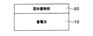
- FIG. 1 is a configuration diagram of a storage battery system according to a first embodiment of the present disclosure. It is a figure for demonstrating the inflow heat amount from the outside with respect to a storage battery system, It is a figure for demonstrating the temperature change of the storage battery by a fixed heat storage part, It is the figure which showed the temperature change of the storage battery in case the maximum temperature of a storage battery is 35 degreeC, and the volume of a solid heat storage part is 0.4L, It is the figure which showed the temperature change of the storage battery in case the maximum temperature of a storage battery is 35 degreeC, and the volume of a solid heat storage part is 1.5L, It is the figure which showed the temperature change of the storage battery in case the maximum temperature of a storage battery is 40 degreeC, and the volume of a solid heat storage part is 1.5L, It is the figure which showed the temperature change of the storage battery in case the maximum temperature of a storage battery is 40 degreeC, and the volume of a solid heat storage part is 1.5L, It is the figure which showed the temperature change of the storage
- the storage battery system is a drive source mounted on an electric vehicle such as a hybrid vehicle.
- the storage battery system is also used for a power source for driving a load such as a motor generator, a power source for an electronic device, and the like.
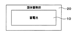
- the storage battery system includes a storage battery 10 and a solid heat storage unit 20.
- the storage battery 10 is a chargeable / dischargeable secondary battery.
- the storage battery 10 is mounted on a vehicle.
- the storage battery 10 includes a plurality of battery cells such as lithium ion batteries and a case that houses the plurality of battery cells.
- the outer shape of the case is a rectangular parallelepiped, for example.
- the case is made of a metal material, a resin material, or the like.
- a plurality of battery cells are connected in series to constitute one battery.
- the battery cell is a plate or block.
- the solid heat storage unit 20 plays a role of maintaining the temperature of the storage battery 10 constant when the temperature of the storage battery 10 reaches the phase transition temperature.
- the solid heat storage unit 20 is configured by a heat storage material that reversibly undergoes phase transition between a solid phase and a solid phase at a certain phase transition temperature with absorption and release of latent heat. That is, the solid heat storage unit 20 causes a solid phase-solid phase transition while maintaining a solid state.
- the solid heat storage unit 20 is configured in a plate shape.
- the solid heat storage unit 20 is in direct contact with the storage battery 10. According to this, since the latent heat can be directly exchanged between the solid heat storage unit 20 and the storage battery 10, the heat retention effect of the storage battery 10 by the solid heat storage unit 20 can be sufficiently obtained.
- the solid heat storage unit 20 is configured to have the same size as one side surface of the storage battery 10. That is, the solid heat storage unit 20 is in contact with the entire side surface of the storage battery 10.
- a method for bringing the solid heat storage unit 20 and the storage battery 10 into direct contact there are a method using grease, a method using a case for pressing the solid heat storage unit 20 and the storage battery 10 together, and the like.
- the heat storage material is configured to include vanadium.
- vanadium dioxide VO 2
- the phase transition temperature of the solid heat storage unit 20 is set to a desired temperature by adding an additive to vanadium dioxide.
- the phase transition temperature is set to 30 ° C., for example.
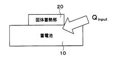
- the temperature of the storage battery 10 rises due to the inflow heat quantity (Q input ) from the outside such as the heat of the vehicle and solar heat.
- the solid heat storage unit 20 is drawn to a size smaller than one side surface of the storage battery 10 in order to illustrate the inflow heat amount.
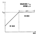
- Equation 1 shows that the cumulative inflow heat quantity Q input up to a certain time is consumed by the temperature rise ⁇ T and the latent heat ⁇ H in the solid-phase state transition of the solid heat storage section 20. In other words, the temperature rise of the storage battery system is consumed by the latent heat ⁇ H, so that the temperature of the storage battery system is kept constant.
- the amount of heat flowing into the storage battery 10 is all used to increase the temperature of the storage battery system. . Therefore, the temperature of the storage battery 10 continues to rise.
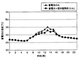
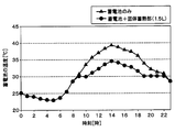
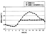
- FIGS. 4 to 7 show the temperature change of the storage battery 10 with respect to time. 4 and 5 show a case where the maximum temperature of the storage battery 10 reaches 35 ° C., and FIGS. 6 and 7 show a case where the maximum temperature of the storage battery 10 reaches 40 ° C.
- the temperature of the storage battery 10 rises from about 6 o'clock, reaches the maximum temperature from 13:00 to 14:00, and falls after 14:00. And in the structure by which the storage battery 10 was equipped with the solid heat storage part 20, it turns out that the temperature rise of the storage battery 10 is suppressed after 8:00.
- the maximum temperature of the storage battery 10 is suppressed by adopting a configuration including not only the storage battery 10 but also the solid heat storage unit 20. Furthermore, since the amount of latent heat absorbed by the solid heat storage unit 20 from the storage battery 10 is increased by increasing the volume of the solid heat storage unit 20, the heat retention effect of the storage battery 10 is improved.
- the solid-state heat storage unit 20 that causes a solid-phase-solid phase transition is mounted on the storage battery 10.
- the container for maintaining the shape of the solid heat storage part 20 can be made unnecessary.
- the thermal resistance of outer walls, such as a container at the time of exchanging latent heat between the storage battery 10 and the solid heat storage part 20, can be reduced.
- the life of the storage battery 10 can be extended by mitigating changes in the temperature of the storage battery 10 without using a heat retaining device such as a heater or a cooling device.
- the temperature retaining device does not operate when the engine is stopped, so that it cannot cope with the temperature change of the storage battery 10.
- the solid heat storage unit 20 according to the present embodiment can obtain a high effect without using a heat retaining device even when the engine is stopped.
- the solid heat storage unit 20 surrounds the storage battery 10.
- the solid heat storage unit 20 is configured in a cylindrical shape and surrounds the entire four side surfaces of the case of the storage battery 10. That is, both end surfaces of the case of the storage battery 10 are exposed from the solid heat storage unit 20.
- the solid heat storage unit 20 can absorb latent heat from multiple directions of the storage battery 10, the heat retention effect of the storage battery 10 by the solid heat storage unit 20 can be sufficiently obtained.
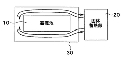
- the storage battery system includes a storage battery 10, a solid heat storage unit 20, and a flow path unit 30.
- the flow path section 30 constitutes a flow path for heat exchange between the storage battery 10 and the solid heat storage section 20 through the heat medium by circulating the heat medium between the storage battery 10 and the solid heat storage section 20.
- the heat medium flows in the space between the storage battery 10 and the inner wall surface of the flow path portion 30.
- the storage battery 10 and the solid heat storage unit 20 are spaced apart.
- the heat medium is, for example, gas or water.
- the solid heat storage unit 20 is solid, there is a merit that it is easy to handle a liquid such as water.
- the storage battery 10 and the solid heat storage part 20 can be arrange
- the configuration of the storage battery system shown in each of the above embodiments is an example, and is not limited to the configuration shown above, and may be another configuration that can realize the present disclosure.
- the storage battery 10 is not limited to being mounted on a vehicle, and the storage battery 10 may be stationary.
- the external shape of the storage battery 10 is not limited to a rectangular parallelepiped as described above, and other external shapes may be adopted.
- the solid heat storage unit 20 is configured in a cylindrical shape that surrounds the storage battery 10, but may also surround the entire storage battery 10. A connector for taking out the power from the storage battery 10 is exposed from the solid heat storage unit 20.
Landscapes
- Engineering & Computer Science (AREA)
- Manufacturing & Machinery (AREA)
- Chemical & Material Sciences (AREA)
- Chemical Kinetics & Catalysis (AREA)
- Electrochemistry (AREA)
- General Chemical & Material Sciences (AREA)
- Secondary Cells (AREA)
- Battery Mounting, Suspending (AREA)
Priority Applications (1)
| Application Number | Priority Date | Filing Date | Title |
|---|---|---|---|
| US15/744,128 US20180212290A1 (en) | 2015-08-07 | 2016-06-08 | Storage battery system |
Applications Claiming Priority (2)
| Application Number | Priority Date | Filing Date | Title |
|---|---|---|---|
| JP2015157042A JP2017037743A (ja) | 2015-08-07 | 2015-08-07 | 蓄電池システム |
| JP2015-157042 | 2015-08-07 |
Publications (1)
| Publication Number | Publication Date |
|---|---|
| WO2017026084A1 true WO2017026084A1 (ja) | 2017-02-16 |
Family
ID=57984166
Family Applications (1)
| Application Number | Title | Priority Date | Filing Date |
|---|---|---|---|
| PCT/JP2016/002775 Ceased WO2017026084A1 (ja) | 2015-08-07 | 2016-06-08 | 蓄電池システム |
Country Status (3)
| Country | Link |
|---|---|
| US (1) | US20180212290A1 (enExample) |
| JP (1) | JP2017037743A (enExample) |
| WO (1) | WO2017026084A1 (enExample) |
Families Citing this family (6)
| Publication number | Priority date | Publication date | Assignee | Title |
|---|---|---|---|---|
| CN108141520A (zh) * | 2015-10-27 | 2018-06-08 | 索尼公司 | 电子设备 |
| JPWO2018135140A1 (ja) * | 2017-01-19 | 2019-11-07 | ソニー株式会社 | 複合材料、電子機器および電子機器の製造方法 |
| JP2020145060A (ja) * | 2019-03-06 | 2020-09-10 | 株式会社日立製作所 | 電池システム及び電池パック |
| JP7218868B2 (ja) * | 2019-06-11 | 2023-02-07 | 株式会社アイシン | 蓄熱放熱システム |
| CN112537385B (zh) * | 2020-12-30 | 2023-03-21 | 山东济燃氢动力有限公司 | 一种氢燃料电池摩托车 |
| CN114865196B (zh) * | 2022-06-10 | 2024-07-19 | 贵州电网有限责任公司 | 一种寒区自控温光伏系统电池箱及控温方法 |
Citations (3)
| Publication number | Priority date | Publication date | Assignee | Title |
|---|---|---|---|---|
| JP2008305575A (ja) * | 2007-06-05 | 2008-12-18 | Denso Corp | 電池温度調節装置 |
| JP2009140786A (ja) * | 2007-12-07 | 2009-06-25 | Sekisui Chem Co Ltd | 車載用組電池 |
| JP2015029036A (ja) * | 2013-06-27 | 2015-02-12 | ソニー株式会社 | 電子機器および電子機器の制御方法 |
Family Cites Families (4)
| Publication number | Priority date | Publication date | Assignee | Title |
|---|---|---|---|---|
| MX2012007895A (es) * | 2010-01-08 | 2012-08-01 | Dow Global Technologies Llc | Administracion termica de una celda electroquimica por medio de una combinacion del fluido de transferencia de calor y un material de cambio de fase. |
| JP5743348B2 (ja) * | 2010-04-15 | 2015-07-01 | エルジー・ケム・リミテッド | バッテリモジュール |
| DE102011002549A1 (de) * | 2011-01-12 | 2012-07-12 | Robert Bosch Gmbh | Batterietemperierung durch Aggregatzustandswechselmaterial |
| BR112015019616A2 (pt) * | 2013-03-12 | 2017-07-18 | Akzo Nobel Chemicals Int Bv | formulação de filtro solar |
-
2015
- 2015-08-07 JP JP2015157042A patent/JP2017037743A/ja active Pending
-
2016
- 2016-06-08 WO PCT/JP2016/002775 patent/WO2017026084A1/ja not_active Ceased
- 2016-06-08 US US15/744,128 patent/US20180212290A1/en not_active Abandoned
Patent Citations (3)
| Publication number | Priority date | Publication date | Assignee | Title |
|---|---|---|---|---|
| JP2008305575A (ja) * | 2007-06-05 | 2008-12-18 | Denso Corp | 電池温度調節装置 |
| JP2009140786A (ja) * | 2007-12-07 | 2009-06-25 | Sekisui Chem Co Ltd | 車載用組電池 |
| JP2015029036A (ja) * | 2013-06-27 | 2015-02-12 | ソニー株式会社 | 電子機器および電子機器の制御方法 |
Also Published As
| Publication number | Publication date |
|---|---|
| US20180212290A1 (en) | 2018-07-26 |
| JP2017037743A (ja) | 2017-02-16 |
Similar Documents
| Publication | Publication Date | Title |
|---|---|---|
| WO2017026084A1 (ja) | 蓄電池システム | |
| Al‐Zareer et al. | A review of novel thermal management systems for batteries | |
| JP6719562B2 (ja) | バッテリーモジュール | |
| JP7034419B2 (ja) | バッテリーモジュール、該バッテリーモジュールを含むバッテリーパック及び該バッテリーパックを含む自動車 | |
| Lin et al. | Experiment and simulation of a LiFePO4 battery pack with a passive thermal management system using composite phase change material and graphite sheets | |
| Liu et al. | Recent developments of thermal management strategies for lithium‐ion batteries: a state‐of‐the‐art review | |
| Yamada et al. | Analysis of a lithium-ion battery cooling system for electric vehicles using a phase-change material and heat pipes | |
| JP6567553B2 (ja) | 電池パック | |
| Lin et al. | Research progress of phase change storage material on power battery thermal management | |
| CN102201603B (zh) | 用于机动车辆的储能器 | |
| KR102023921B1 (ko) | 배터리 모듈 | |
| JP2013178966A (ja) | 電池モジュール | |
| Sikarwar et al. | Battery thermal management system for the cooling of Li-Ion batteries, used in electric vehicles | |
| JP2012048905A (ja) | 冷却材を備える電池、並びに冷却材を備える組電池 | |
| US20210083342A1 (en) | Battery Module with Enhanced Cooling Efficiency, and Battery Pack Comprising Same | |
| WO2013141242A1 (ja) | イオン液体を用いたリチウムイオン二次電池及びリチウムイオン二次電池モジュール並びにこれらの保温装置 | |
| JP2020140929A (ja) | 電池パック | |
| WO2020079965A1 (ja) | 電池パック | |
| Dolla et al. | Investigations of phase change materials in battery thermal management systems for electric vehicles: a review | |
| Kibria et al. | A review on composite phase change materials and fins-based li-ion battery thermal management systems with design perspectives and future outlooks | |
| Swamy et al. | Experimental and Numerical Investigation for Optimization of a Hybrid Battery Thermal Management System Based on Phase Change Material and Air Convection | |
| US11108103B2 (en) | Thermal management system including phase-change materials having different phase-change temperatures for an on-vehicle battery | |
| Wei et al. | Experimental study of a thermal cooling technique for cylindrical batteries | |
| JP6289237B2 (ja) | 組電池 | |
| CN203617407U (zh) | 储能蓄电池 |
Legal Events
| Date | Code | Title | Description |
|---|---|---|---|
| 121 | Ep: the epo has been informed by wipo that ep was designated in this application |
Ref document number: 16834788 Country of ref document: EP Kind code of ref document: A1 |
|
| WWE | Wipo information: entry into national phase |
Ref document number: 15744128 Country of ref document: US |
|
| NENP | Non-entry into the national phase |
Ref country code: DE |
|
| 122 | Ep: pct application non-entry in european phase |
Ref document number: 16834788 Country of ref document: EP Kind code of ref document: A1 |