WO2017022772A1 - 自動変速機の制御装置及び自動変速機の制御方法 - Google Patents
自動変速機の制御装置及び自動変速機の制御方法 Download PDFInfo
- Publication number
- WO2017022772A1 WO2017022772A1 PCT/JP2016/072694 JP2016072694W WO2017022772A1 WO 2017022772 A1 WO2017022772 A1 WO 2017022772A1 JP 2016072694 W JP2016072694 W JP 2016072694W WO 2017022772 A1 WO2017022772 A1 WO 2017022772A1
- Authority
- WO
- WIPO (PCT)
- Prior art keywords
- determination
- transmission mechanism
- condition
- rotational speed
- satisfied
- Prior art date
- Legal status (The legal status is an assumption and is not a legal conclusion. Google has not performed a legal analysis and makes no representation as to the accuracy of the status listed.)
- Ceased
Links
Images


Classifications
-
- F—MECHANICAL ENGINEERING; LIGHTING; HEATING; WEAPONS; BLASTING
- F16—ENGINEERING ELEMENTS AND UNITS; GENERAL MEASURES FOR PRODUCING AND MAINTAINING EFFECTIVE FUNCTIONING OF MACHINES OR INSTALLATIONS; THERMAL INSULATION IN GENERAL
- F16H—GEARING
- F16H59/00—Control inputs to control units of change-speed- or reversing-gearings for conveying rotary motion
- F16H59/36—Inputs being a function of speed
- F16H59/38—Inputs being a function of speed of gearing elements
- F16H59/40—Output shaft speed
-
- F—MECHANICAL ENGINEERING; LIGHTING; HEATING; WEAPONS; BLASTING
- F16—ENGINEERING ELEMENTS AND UNITS; GENERAL MEASURES FOR PRODUCING AND MAINTAINING EFFECTIVE FUNCTIONING OF MACHINES OR INSTALLATIONS; THERMAL INSULATION IN GENERAL
- F16H—GEARING
- F16H59/00—Control inputs to control units of change-speed- or reversing-gearings for conveying rotary motion
- F16H59/36—Inputs being a function of speed
- F16H59/38—Inputs being a function of speed of gearing elements
- F16H59/42—Input shaft speed
-
- F—MECHANICAL ENGINEERING; LIGHTING; HEATING; WEAPONS; BLASTING
- F16—ENGINEERING ELEMENTS AND UNITS; GENERAL MEASURES FOR PRODUCING AND MAINTAINING EFFECTIVE FUNCTIONING OF MACHINES OR INSTALLATIONS; THERMAL INSULATION IN GENERAL
- F16H—GEARING
- F16H61/00—Control functions within control units of change-speed- or reversing-gearings for conveying rotary motion ; Control of exclusively fluid gearing, friction gearing, gearings with endless flexible members or other particular types of gearing
- F16H61/12—Detecting malfunction or potential malfunction, e.g. fail safe ; Circumventing or fixing failures
-
- F—MECHANICAL ENGINEERING; LIGHTING; HEATING; WEAPONS; BLASTING
- F16—ENGINEERING ELEMENTS AND UNITS; GENERAL MEASURES FOR PRODUCING AND MAINTAINING EFFECTIVE FUNCTIONING OF MACHINES OR INSTALLATIONS; THERMAL INSULATION IN GENERAL
- F16H—GEARING
- F16H61/00—Control functions within control units of change-speed- or reversing-gearings for conveying rotary motion ; Control of exclusively fluid gearing, friction gearing, gearings with endless flexible members or other particular types of gearing
- F16H61/68—Control functions within control units of change-speed- or reversing-gearings for conveying rotary motion ; Control of exclusively fluid gearing, friction gearing, gearings with endless flexible members or other particular types of gearing specially adapted for stepped gearings
- F16H61/682—Control functions within control units of change-speed- or reversing-gearings for conveying rotary motion ; Control of exclusively fluid gearing, friction gearing, gearings with endless flexible members or other particular types of gearing specially adapted for stepped gearings with interruption of drive
Definitions
- the present invention relates to an automatic transmission control device and an automatic transmission control method.
- JP1-172663A discloses a technique for detecting a gear ratio abnormality, which is an abnormality in a gear ratio, based on a comparison between an instruction gear ratio and an actual gear ratio of the transmission.
- the stepped transmission mechanism of the automatic transmission may enter a neutral state even though the neutral instruction is not issued.
- the neutral detection condition which is a condition for establishing neutral detection for detecting such a state, can be set as follows.
- the stepped transmission mechanism when the stepped transmission mechanism is in a neutral state while the vehicle is traveling, the input rotational speed of the stepped transmission mechanism is increased by the power from the traveling drive source. As a result, the actual gear ratio of the stepped transmission mechanism obtained by dividing the input rotation speed by the output rotation speed increases.
- the neutral detection condition can be a condition including that the actual gear ratio is larger than the command gear ratio by a predetermined amount or more.
- the output rotational speed constituting the parameter of the actual gear ratio becomes lower as the vehicle speed is lower.
- the actual gear ratio is more likely to change greatly in accordance with the input rotational speed when the vehicle speed is low than when the vehicle speed is high.
- the neutral detection condition is satisfied and an erroneous neutral detection determination is made even if the input rotational speed shift is slight and is actually normal.
- the present invention has been made in view of such technical problems, and it is an object of the present invention to provide an automatic transmission control device and an automatic transmission control method that can improve neutral detection determination of a stepped transmission mechanism. .
- a control device for an automatic transmission is a control device for an automatic transmission that is provided in a vehicle and has a stepped transmission mechanism, and includes an input side rotational speed and an output side rotational speed of the stepped transmission mechanism.
- a first determination unit that performs a first determination that is a determination that the first condition is satisfied; and
- a second determination is made to determine that the second condition is satisfied
- a third determination unit that performs a neutral detection determination that is a determination that a neutral state of the stepped transmission mechanism has been detected when both the first determination and the second determination are established.
- An automatic transmission control device is an automatic transmission control device provided in a vehicle and having a stepped transmission mechanism, wherein the vehicle speed is higher than a set vehicle speed, and the stepped transmission mechanism is When a first condition including that the ratio of the input side rotational speed and the output side rotational speed is outside the first normal detection range is satisfied, a first determination is made that is a determination that the first condition is satisfied. When a second condition is satisfied that includes the determination unit and the vehicle speed being lower than the set vehicle speed and the difference between the input side rotational speed and the output side rotational speed of the stepped transmission mechanism being outside the second normal detection range.
- a neutral state of the stepped transmission mechanism is detected when one of the first determination and the second determination is satisfied, and a second determination unit that performs a second determination that is a determination that the second condition is satisfied 3rd size to perform neutral detection judgment It has a part, a.
- a method for controlling an automatic transmission provided in a vehicle and having a stepped transmission mechanism wherein a ratio between an input side rotational speed and an output side rotational speed of the stepped transmission mechanism is first.
- a first condition including being outside the normal detection range is satisfied
- a first determination that is a determination that the first condition is satisfied is performed, and an input side rotational speed and an output side of the stepped transmission mechanism are determined.
- an automatic transmission control method including performing a neutral detection determination that is a determination that a neutral state of the stepped transmission mechanism has been detected.
- a method for controlling an automatic transmission provided in a vehicle and having a stepped transmission mechanism wherein the vehicle speed is higher than a set vehicle speed and the input side rotational speed of the stepped transmission mechanism is And when the first condition including that the ratio of the output side rotational speed is outside the first normal detection range is satisfied, a first determination that is a determination that the first condition is satisfied is performed; The second condition is satisfied when a second condition is established that is lower than the set vehicle speed and includes that the difference between the input side rotational speed and the output side rotational speed of the stepped transmission mechanism is outside the second normal detection range.
- a neutral detection determination that is a determination that a neutral state of the stepped transmission mechanism has been detected when one of the first determination and the second determination is established.
- automatic transmission control including The law is provided.
- the neutral detection condition is not satisfied by the second condition when it is actually normal. It is possible to prevent the detection determination. Therefore, according to these aspects, the neutral detection determination of the stepped transmission mechanism can be improved.
- FIG. 1 is a diagram illustrating a main part of a vehicle including a transmission.
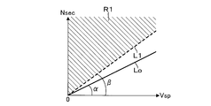
- FIG. 2A is an explanatory diagram of a first condition for determining neutral detection according to the embodiment.
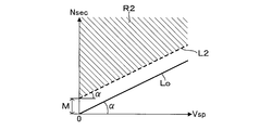
- FIG. 2B is an explanatory diagram of a second condition for determining neutral detection according to the embodiment.
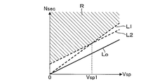
- FIG. 2C is an explanatory diagram of neutral detection determination according to the embodiment.
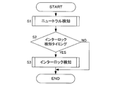
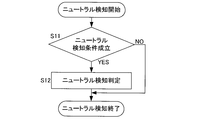
- FIG. 3 shows an example of a main routine of control according to the embodiment.
- FIG. 4 shows an example of a subroutine for performing neutral detection.
- FIG. 5 shows an example of a subroutine for performing interlock detection.
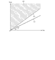
- FIG. 6 is a diagram illustrating a comparative example of the neutral detection determination.
- FIG. 1 is a diagram showing a main part of a vehicle including a transmission 100.
- the vehicle includes an engine 1, a torque converter 2, a variator 20, an auxiliary transmission mechanism 30, an axle portion 4, and drive wheels 5.
- Engine 1 constitutes a drive source for the vehicle.
- the torque converter 2 transmits power through the fluid.
- the variator 20 and the auxiliary transmission mechanism 30 output the input rotational speed at a rotational speed corresponding to the gear ratio.
- the axle portion 4 includes a reduction gear, a differential device, and a drive axle. The power of the engine 1 is transmitted to the drive wheels 5 through the torque converter 2, the variator 20, the auxiliary transmission mechanism 30 and the axle portion 4.
- the variator 20 is a continuously variable transmission mechanism, and includes a primary pulley 21, a secondary pulley 22, and a belt 23.
- PRI primary pulley
- SEC secondary pulley
- the PRI pulley 21 includes a fixed pulley 21a, a movable pulley 21b, and a PRI chamber 21c. In the PRI pulley 21, the PRI pressure is supplied to the PRI chamber 21c.
- the SEC pulley 22 includes a fixed pulley 22a, a movable pulley 22b, and an SEC chamber 22c. In the SEC pulley 22, the SEC pressure is supplied to the SEC chamber 22c.
- the belt 23 has a V-shaped sheave surface formed by a fixed pulley 21 a and a movable pulley 21 b of the PRI pulley 21, and a V-shape formed by a fixed pulley 22 a and a movable pulley 22 b of the SEC pulley 22. Wound around the sheave surface.
- the variator 20 constitutes a belt-type continuously variable transmission mechanism that changes speed by changing the winding diameter of the belt 23 by changing the groove widths of the PRI pulley 21 and the SEC pulley 22 respectively.
- the PRI pressure and the SEC pressure are generated by the hydraulic control circuit 11 using the line pressure PL as a source pressure.
- the line pressure PL may be applied to one of the PRI pressure and the SEC pressure.
- the variator 20 can be configured as a univariator variator.
- the auxiliary transmission mechanism 30 is a stepped transmission mechanism and has two forward speeds and one reverse speed.
- the subtransmission mechanism 30 has a first speed and a second speed having a smaller gear ratio than the first speed as a forward gear.
- the auxiliary transmission mechanism 30 is provided in series on the output side of the variator 20 in the power transmission path from the engine 1 to the drive wheels 5.
- the subtransmission mechanism 30 may be directly connected to the variator 20 or may be indirectly connected to the variator 20 through another configuration such as a gear train.
- the sub-transmission mechanism 30 includes a planetary gear mechanism 31 and a plurality of frictional engagement elements including a low brake 32, a high clutch 33, and a Rev brake 34.
- the gear position of the subtransmission mechanism 30 is changed by adjusting the hydraulic pressure supplied to the plurality of friction engagement elements and changing the engagement / release state of the plurality of friction engagement elements.
- the gear position becomes the first speed. Further, when the high clutch 33 is engaged and the low brake 32 and the rev brake 34 are released, the gear position becomes the second speed. Further, when the Rev brake 34 is engaged and the Low brake 32 and the High clutch 33 are released, the shift speed is reverse.
- the gear ratio is changed in each of the variator 20 and the auxiliary transmission mechanism 30. For this reason, in the vehicle, a speed change according to a through speed ratio that is a speed ratio of the variator 20 and the subtransmission mechanism 30 is performed.
- the transmission ratio is a value obtained by dividing the input rotation speed by the output rotation speed
- the through transmission ratio is a transmission ratio obtained by multiplying the transmission ratio of the variator 20 by the transmission ratio of the auxiliary transmission mechanism 30.
- the variator 20 and the auxiliary transmission mechanism 30 constitute an automatic transmission mechanism 3.
- the variator 20 and the auxiliary transmission mechanism 30 may be configured as separate transmission mechanisms in structure.
- the vehicle further includes an oil pump 10, a hydraulic control circuit 11, and a controller 12.
- Oil pump 10 pumps oil.
- the oil pump 10 a mechanical oil pump that is driven by the power of the engine 1 can be used.
- the hydraulic control circuit 11 adjusts the pressure of the oil pumped from the oil pump 10, that is, the hydraulic pressure, and transmits it to each part of the variator 20 and the auxiliary transmission mechanism 30.
- the hydraulic control circuit 11 for example, the line pressure PL, the PRI pressure, and the SEC pressure are adjusted.
- the controller 12 is an electronic control device and controls the hydraulic control circuit 11. Output signals from the rotation sensor 41, the rotation sensor 42, and the rotation sensor 43 are input to the controller 12.
- the rotation sensor 41 is a variator input side rotation sensor for detecting the rotation speed on the input side of the variator 20.
- the rotation sensor 42 is a variator output side rotation sensor for detecting the rotation speed on the output side of the variator 20. Specifically, the rotation sensor 42 detects the rotation speed on the output side of the variator 20 and on the input side of the auxiliary transmission mechanism 30.
- the rotation sensor 43 is a sub transmission mechanism output side rotation sensor for detecting the rotation speed on the output side of the sub transmission mechanism 30.
- the rotation speed on the input side of the variator 20 is specifically the rotation speed of the input shaft of the variator 20.
- the rotational speed on the input side of the variator 20 may be, for example, the rotational speed at a position where the gear train is sandwiched between the variator 20 in the power transmission path described above. The same applies to the rotational speed on the output side of the variator 20 and the rotational speed on the output side of the auxiliary transmission mechanism 30.
- controller 12 also receives output signals from the accelerator opening sensor 44, the inhibitor switch 45, the engine rotation sensor 46, and the like.
- the accelerator opening sensor 44 detects an accelerator opening APO that represents the amount of operation of the accelerator pedal.
- the inhibitor switch 45 detects the position of the select lever.
- the engine rotation sensor 46 detects the rotation speed Ne of the engine 1.
- the controller 12 can detect the vehicle speed Vsp based on the output signal of the rotation sensor 43.
- the controller 12 generates a shift control signal based on these signals, and outputs the generated shift control signal to the hydraulic control circuit 11.
- the hydraulic control circuit 11 controls the line pressure, the PRI pressure, the SEC pressure, and switches the hydraulic path based on the shift control signal from the controller 12.
- the shift control signal includes a neutral instruction of the subtransmission mechanism 30 that is an instruction for setting the subtransmission mechanism 30 to the neutral state.
- the transmission 100 is an automatic transmission. In addition to the variator 20 and the auxiliary transmission mechanism 30, the hydraulic control circuit 11 and the controller 12 that control the transmission ratio in this way, the rotation sensor 41, the rotation sensor 42, and the rotation sensor 43 are provided. It is configured.
- the transmission 100 may be configured to further include, for example, a pressure sensor that detects hydraulic pressure supplied to the plurality of frictional engagement elements of the auxiliary transmission mechanism 30.
- the subtransmission mechanism 30 may be in a neutral state although no neutral instruction is given.
- Neutral detection for detecting such a state can be performed, for example, by performing the following neutral detection determination.
- FIG. 6 is a diagram showing a comparative example of the neutral detection determination.
- the rotation speed Nsec is the rotation speed of the SEC pulley 22.
- the input side rotational speed of the auxiliary transmission mechanism 30 detected based on the output of the rotation sensor 42 is used as the rotational speed Nsec.
- the vehicle speed Vsp the output side rotational speed of the auxiliary transmission mechanism 30 detected based on the output of the rotation sensor 43 is used. Therefore, at a certain operating point indicated by the rotational speed Nsec and the vehicle speed Vsp, the ratio of the rotational speed Nsec and the vehicle speed Vsp obtained by dividing the rotational speed Nsec by the vehicle speed Vsp indicates the actual speed ratio of the auxiliary transmission mechanism 30.
- the straight line Lo is a straight line according to the commanded gear ratio of the sub-transmission mechanism 30, in other words, the normal gear ratio of the sub-transmission mechanism 30, and the slope ⁇ of the straight line Lo represents the commanded gear ratio.
- the command speed ratio is set in advance in the controller 12 according to the gear position of the subtransmission mechanism 30.
- the first straight line L1 indicates a straight line that divides the first region R1.
- the first region R1 is divided by the first straight line L1 to the side where the rotational speed Nsec is higher than that of the first straight line L1.
- the first region R1 indicates a region of the rotational speed Nsec and the vehicle speed Vsp corresponding to the ratio of the rotational speed Nsec and the vehicle speed Vsp, and thus the actual transmission ratio of the auxiliary transmission mechanism 30 being outside the first normal detection range.
- the first region R1 indicates an operating point region corresponding to the actual gear ratio outside the first normal detection range.
- the engine 1 is blown when the auxiliary transmission mechanism 30 is in a neutral state while the vehicle is running, and the rotational speed Nsec is increased accordingly. Is set to detect.
- the first region R1 can be set in advance by experiments or the like.
- neutral detection determination is performed as described below.
- FIG. 2A is an explanatory diagram of a first condition for determining neutral detection according to the present embodiment.
- FIG. 2B is an explanatory diagram of a second condition for determining neutral detection according to the present embodiment.
- FIG. 2C is an explanatory diagram of neutral detection determination according to the present embodiment. Note that FIG. 2A is the same as FIG.
- the second straight line L2 indicates a straight line dividing the second region R2.
- the second straight line L2 has the same inclination ⁇ as the normal straight line Lo, and is set such that the rotational speed Nsec is higher than the straight line Lo by the rotational speed M at the same vehicle speed Vsp.
- the second region R2 is divided by the second straight line L2 to the side where the rotational speed Nsec is higher than that of the second straight line L2.
- the second region R2 is an operating point region corresponding to the difference between the rotational speed Nsec and the vehicle speed Vsp outside the second normal detection range.
- the difference between the rotational speed Nsec and the vehicle speed Vsp is referred to as an input / output rotational speed difference.
- the input / output rotational speed difference is a value obtained by subtracting the vehicle speed Vsp from the rotational speed Nsec.
- the corresponding operating point is included in the second region R2, and the input / output rotational speed difference is 2 Out of the normal detection range.
- the rotational speed Nsec is the same as the rotational speed Nsec based on the straight line Lo when normal
- the rotational speed M is the same as the vehicle speed Vsp. It can be said that the case is very different.
- the second condition for the neutral detection determination is a condition including that the input / output rotational speed difference is outside the second normal range. Then, when both the first condition and the second condition are satisfied, the neutral detection determination is performed. That is, as shown in FIG. 2C, when an operating point is included in the overlapping region R where the first region R1 and the second region R2 overlap, the neutral detection determination is performed.
- the overlapping region R is divided by the first straight line L1 to the side where the rotational speed Nsec is higher than the first straight line L1. Further, the superimposition region R is divided by the second straight line L2 to the higher rotational speed Nsec than the second straight line L2 when the vehicle speed Vsp is lower than the set vehicle speed Vsp1.
- the set vehicle speed Vsp1 is set at the intersection of the first straight line L1 and the second straight line L2.
- FIG. 3 shows an example of a main routine of control performed by the controller 12.
- FIG. 4 shows an example of a subroutine for performing neutral detection of the auxiliary transmission mechanism 30.
- FIG. 5 shows an example of a subroutine for detecting the interlock of the auxiliary transmission mechanism 30.
- the controller 12 can repeatedly execute the processing shown in the flowchart of FIG. 3 every minute time.
- the controller 12 can perform the process shown in the flowchart of FIG. 3 while the vehicle is traveling.
- the controller 12 performs neutral detection in step S1. Further, the controller 12 determines whether or not it is an interlock detection timing in step S2. That is, in the present embodiment, the interlock detection timing is set for each predetermined time interval.
- the predetermined time interval can be set in advance by experiments or the like.
- step S2 If the determination in step S2 is negative, the process of this flowchart is temporarily terminated. If the determination is affirmative in step S2, the process proceeds to step S3. In step S3, the controller 12 performs interlock detection. After step S3, the process of this flowchart is once ended.
- step S1 is performed as shown in FIG.
- step S3 is specifically performed as shown in FIG.
- step S11 it is determined whether or not the operating point is included in the overlapping region R. By determining whether or not the operating point is included in the overlapping region R, it is simultaneously determined whether or not the operating point is included in the first region R1 and whether or not the operating point is included in the second region R2.
- step S11 by simultaneously determining these, it is simultaneously determined whether or not the first condition is satisfied and whether or not the second condition is satisfied. If both the first determination, which is a determination that the first condition is satisfied, and the second determination, which is a determination that the second condition is satisfied, an affirmative determination is made in step S11.
- the first condition and the second condition constitute the neutral detection condition.
- the neutral detection condition is set as a condition for detecting a neutral abnormality or a temporary neutral state.
- the neutral abnormality is an abnormality in which the auxiliary transmission mechanism 30 cannot be engaged even if the auxiliary engagement mechanism 30 is engaged, and the auxiliary transmission mechanism 30 enters the neutral state.
- the neutral abnormality may occur due to, for example, a failure of a solenoid that controls the frictional engagement element of the auxiliary transmission mechanism 30 or the hydraulic pressure supplied to the frictional engagement element.
- the temporary neutral state is different from the neutral state due to the above-described neutral abnormality in that the auxiliary transmission mechanism 30 is temporarily in the neutral state.
- the temporary neutral state is, for example, a time lag from when the command current is supplied to the solenoid to fasten the frictional engagement element of the auxiliary transmission mechanism 30 until the hydraulic pressure corresponding to the command current is actually supplied to the frictional engagement element, That is, it may occur due to a delay in response of the hydraulic control.
- the neutral detection condition is set as a neutral detection establishment condition for detecting a state in which the subtransmission mechanism 30 is in the neutral state even though the neutral instruction is not issued.
- the neutral detection condition may be a condition including that the selected range is a forward travel range such as a D range.
- step S11 If the determination in step S11 is negative, the process of this flowchart ends. If the determination in step S11 is affirmative, the process proceeds to step S12.
- step S12 the controller 12 performs a neutral detection determination of the subtransmission mechanism 30, that is, a determination that the neutral state of the subtransmission mechanism 30 has been detected.
- the neutral detection determination is a determination that a state in which the auxiliary transmission mechanism 30 is in the neutral state is detected although the neutral instruction is not issued.
- Neutral detection determination can be performed, for example, by turning on a flag.
- the controller 12 determines whether or not the interlock detection condition of the auxiliary transmission mechanism 30 is satisfied in step S21.
- the interlock detection condition is set as a condition for establishing the interlock detection for detecting the interlock state of the auxiliary transmission mechanism 30.
- the interlock detection condition includes that the actual transmission ratio of the auxiliary transmission mechanism 30 is outside the third normal detection range, and that the absolute value of the deceleration of the output shaft rotation of the auxiliary transmission mechanism 30 is greater than the set value. . This is due to the following reason.
- the interlock state of the sub-transmission mechanism 30 is a state in which a plurality of frictional engagement elements of the sub-transmission mechanism 30 try to fasten in a combination such that the rotation of the planetary gear mechanism 31 approaches zero. In the middle, a plurality of frictional engagement elements are going to be engaged, but the output side rotational speed does not become zero.
- the interlock detection condition may be a condition including that the selected range is a forward travel range such as a D range.
- step S21 If the determination in step S21 is negative, this flowchart ends. If the determination in step S21 is affirmative, the process proceeds to step S22.
- step S22 the controller 12 performs an interlock detection determination of the subtransmission mechanism 30, that is, a determination that the interlock state of the subtransmission mechanism 30 has been detected.
- the interlock detection determination can be performed, for example, by turning on a flag.
- Interlock detection determination may be performed by determining that the interlock detection condition is satisfied when the interlock detection condition is satisfied without turning on the special flag. The same applies to the neutral detection determination.
- the first determination, the second determination, and the neutral detection determination are performed not only when they are performed separately, but also by collectively performing the first determination and the second determination, and further by this, the neutral detection determination is performed. This includes cases where
- the controller 12 constitutes a control device for the transmission 100, that is, a control device for an automatic transmission.
- the controller 12 functions as a first determination unit, a second determination unit, and a third determination unit by performing the process of step S1 and making an affirmative determination in step S1.
- the controller 12 functions as a fourth determination unit by performing the process of step S22 following the positive determination of step S21.
- the controller 12 has these functional units by functioning as these functional units.
- the control device of the transmission 100 may be grasped as being realized by the hydraulic control circuit 11 and the controller 12.
- the controller 12 is a control device for the transmission 100 that is provided in the vehicle and has the auxiliary transmission mechanism 30, and a first condition is satisfied that includes that the actual transmission ratio of the auxiliary transmission mechanism 30 is outside the first normal detection range. Then, a first determination that is a determination of establishment of the first condition is performed. Further, when the second condition including that the input / output rotational speed difference of the auxiliary transmission mechanism 30 is outside the second normal detection range is satisfied, the controller 12 performs a second determination that is a determination of the second condition. In addition, when both the first determination and the second determination are established, the controller 12 performs a neutral detection determination of the auxiliary transmission mechanism 30.
- the controller 12 configured in this manner, even if the rotational speed Nsec is deviated due to an error or the like, if the normal condition is actually normal, the neutral detection condition is not satisfied by the second condition. It is possible to prevent the detection determination. That is, it is possible to prevent erroneous neutral detection determination by appropriately reducing the detection sensitivity of neutral detection according to the second condition. Therefore, the neutral detection determination of the auxiliary transmission mechanism 30 can be improved.
- the neutral detection determination can be performed without performing the case classification based on the vehicle speed Vsp as described later. For this reason, compared with the case where neutral detection determination is further performed using a vehicle speed sensor for detection of the vehicle speed Vsp, for example, the accumulation of errors can be suppressed and accuracy can be improved by suppressing the number of sensors to be used. .
- controller 12 performs an interlock detection determination of the auxiliary transmission mechanism 30 when the interlock detection condition is satisfied.
- the controller 12 configured in this way, it is possible to further determine the abnormality of the interlock according to the interlock detection condition in which the detection condition for the neutral detection condition and the input / output rotational speed are different. That is, the interlock abnormality can be determined as the interlock abnormality without being determined as the gear abnormality together with the neutral abnormality or the temporary neutral state. .
- the controller 12 may perform the case classification based on the vehicle speed Vsp when performing the neutral detection determination.
- the first condition is a condition including that the vehicle speed Vsp is higher than the set vehicle speed Vsp1 described above with reference to FIG. 2C and that the actual speed ratio of the auxiliary transmission mechanism 30 is outside the first normal detection range.
- the second condition may be a condition including that the vehicle speed Vsp is lower than the set vehicle speed Vsp1 and the input / output rotational speed is out of the second normal detection range.
- the controller 12 can be configured to perform the neutral detection determination of the auxiliary transmission mechanism 30 when one of the first determination and the second determination is established.
- the controller 12 can prevent erroneous determination of neutral detection by appropriately reducing the detection sensitivity of neutral detection according to the second condition. Therefore, the neutral detection determination of the auxiliary transmission mechanism 30 can be improved.
- the ratio of the input side rotational speed and the output side rotational speed of the subtransmission mechanism 30 may be set to, for example, the actual reduction ratio of the subtransmission mechanism 30, that is, the value obtained by dividing the output rotational speed by the input rotational speed.
- the condition that the ratio of the input side rotational speed and the output side rotational speed of the auxiliary transmission mechanism 30 is outside the first normal detection range may be set in accordance with such setting.
- the input / output rotational speed difference of the auxiliary transmission mechanism 30 may be set to a value obtained by subtracting the rotational speed Nsec from the vehicle speed Vsp, for example, or may be set to an absolute value obtained by subtracting the other from one of these. Good.
- the condition that the input / output rotational speed difference of the auxiliary transmission mechanism 30 is outside the second normal detection range may be set in accordance with such setting.
- the auxiliary transmission mechanism 30 is a stepped transmission mechanism.
- the stepped transmission mechanism may be, for example, a so-called automatic transmission that is a stepped automatic transmission mechanism.
- each functional unit may be configured by a plurality of controllers, for example.
Landscapes
- Engineering & Computer Science (AREA)
- General Engineering & Computer Science (AREA)
- Mechanical Engineering (AREA)
- Control Of Transmission Device (AREA)
Abstract
副変速機構(30)を有する変速機(20,30)における制御装置(12)であり、副変速機構の実変速比が第1正常検出範囲外となる第1条件が成立し、且つ副変速機構の入出力回転速度差が第2正常検出範囲外となる第2条件が成立した場合に、副変速機構がニュートラル状態であると判定する制御装置に関する。 また、副変速機構を有する変速機における制御装置であり、車速が設定車速よりも高く、且つ副変速機構の副変速機構の入出力回転速度の比が第1正常検出範囲外となる第3条件、又は、車速が設定車速よりも低く、且つ副変速機構の入出力回転速度差が第2正常検出範囲外となる第4条件の何れか一方の条件が成立すると、副変速機構がニュートラル状態であると判定する制御装置に関する。 更に、前記第1条件及び第2条件に基づいてニュートラル判定を行う制御方法、及び、前記第3条件及び第4条件に基づいてニュートラル判定を行う制御方法に関する。
Description
本発明は、自動変速機の制御装置及び自動変速機の制御方法に関する。
JP1-172663Aには、変速機の指示変速比及び実変速比の比較に基づき、変速比の異常であるギヤ比異常を検出する技術が開示されている。
自動変速機の有段変速機構は、ニュートラル指示をしていないにも関わらず、ニュートラル状態になることがある。このような状態を検知するニュートラル検知の成立条件であるニュートラル検知条件は、次のように設定することができる。
ここで、車両走行中に有段変速機構がニュートラル状態になると、走行用駆動源からの動力によって、有段変速機構の入力回転速度は増加する。これにより、入力回転速度を出力回転速度で除算して得られる有段変速機構の実変速比は増加する。
このため、ニュートラル検知条件は、実変速比が指示変速比よりも所定以上大きいこと、を含む条件とすることができる。
ところが、実変速比の母数を構成する出力回転速度は、車速が低い場合ほど低くなる。このため、低車速の場合には高車速の場合よりも、実変速比が入力回転速度に応じて大きく変化し易くなる。結果、低車速の場合には、入力回転速度のずれがわずかであり実際には正常な場合であっても、ニュートラル検知条件が成立し、誤ったニュートラル検知判定をしてしまう虞がある。
本発明はこのような技術的課題に鑑みてなされたもので、有段変速機構のニュートラル検知判定を改善可能な自動変速機の制御装置及び自動変速機の制御方法を提供することを目的とする。
本発明のある態様の自動変速機の制御装置は、車両に設けられ有段変速機構を有する自動変速機の制御装置であって、前記有段変速機構の入力側回転速度及び出力側回転速度の比が第1正常検出範囲外であること、を含む第1条件が成立すると、前記第1条件が成立したとの判定である第1判定を行う第1判定部と、前記有段変速機構の入力側回転速度及び出力側回転速度の差が第2正常検出範囲外であること、を含む第2条件が成立すると、前記第2条件が成立したとの判定である第2判定を行う第2判定部と、前記第1判定及び前記第2判定の双方が成立すると、前記有段変速機構のニュートラル状態を検知したとの判定であるニュートラル検知判定を行う第3判定部と、を有する。
本発明の別の態様の自動変速機の制御装置は、車両に設けられ有段変速機構を有する自動変速機の制御装置であって、車速が設定車速よりも高く、且つ前記有段変速機構の入力側回転速度及び出力側回転速度の比が第1正常検出範囲外であること、を含む第1条件が成立すると、前記第1条件が成立したとの判定である第1判定を行う第1判定部と、車速が前記設定車速よりも低く、且つ前記有段変速機構の入力側回転速度及び出力側回転速度の差が第2正常検出範囲外であること、を含む第2条件が成立すると、前記第2条件が成立したとの判定である第2判定を行う第2判定部と、前記第1判定又は前記第2判定の一方が成立すると、前記有段変速機構のニュートラル状態を検知したとの判定であるニュートラル検知判定を行う第3判定部と、を有する。
本発明の別の態様によれば、車両に設けられ有段変速機構を有する自動変速機の制御方法であって、前記有段変速機構の入力側回転速度及び出力側回転速度の比が第1正常検出範囲外であること、を含む第1条件が成立すると、前記第1条件が成立したとの判定である第1判定を行うことと、前記有段変速機構の入力側回転速度及び出力側回転速度の差が第2正常検出範囲外であること、を含む第2条件が成立すると、前記第2条件が成立したとの判定である第2判定を行うことと、前記第1判定及び前記第2判定の双方が成立すると、前記有段変速機構のニュートラル状態を検知したとの判定であるニュートラル検知判定を行うことと、を含む自動変速機の制御方法が提供される。
本発明のさらに別の態様によれば、車両に設けられ有段変速機構を有する自動変速機の制御方法であって、車速が設定車速よりも高く、且つ前記有段変速機構の入力側回転速度及び出力側回転速度の比が第1正常検出範囲外であること、を含む第1条件が成立すると、前記第1条件が成立したとの判定である第1判定を行うことと、車速が前記設定車速よりも低く、且つ前記有段変速機構の入力側回転速度及び出力側回転速度の差が第2正常検出範囲外であることを含む第2条件が成立すると、前記第2条件が成立したとの判定である第2判定を行うことと、前記第1判定又は前記第2判定の一方が成立すると、前記有段変速機構のニュートラル状態を検知したとの判定であるニュートラル検知判定を行うことと、を含む自動変速機の制御方法が提供される。
これらの態様によれば、有段変速機構の入力回転速度に誤差等によるずれがあっても、実際には正常な場合には、ニュートラル検知条件が第2条件によって不成立になるので、誤ったニュートラル検知判定を行うことを防止できる。したがって、これらの態様によれば、有段変速機構のニュートラル検知判定を改善することができる。
以下、添付図面を参照しながら本発明の実施形態について説明する。
図1は、変速機100を含む車両の要部を示す図である。車両は、エンジン1と、トルクコンバータ2と、バリエータ20と、副変速機構30と、車軸部4と、駆動輪5と、を備える。
エンジン1は、車両の駆動源を構成する。トルクコンバータ2は、流体を介して動力を伝達する。バリエータ20と副変速機構30とは、入力された回転速度を変速比に応じた回転速度で出力する。車軸部4は、減速ギヤや差動装置や駆動車軸を有して構成される。エンジン1の動力は、トルクコンバータ2、バリエータ20、副変速機構30及び車軸部4を介して駆動輪5に伝達される。
バリエータ20は無段変速機構であり、プライマリプーリ21と、セカンダリプーリ22と、ベルト23と、を備える。以下では、プライマリをPRIと称し、セカンダリをSECと称す。
PRIプーリ21は、固定プーリ21aと、可動プーリ21bと、PRI室21cと、を有する。PRIプーリ21では、PRI室21cにPRI圧が供給される。
SECプーリ22は、固定プーリ22aと、可動プーリ22bと、SEC室22cと、を有する。SECプーリ22では、SEC室22cにSEC圧が供給される。
ベルト23は、PRIプーリ21の固定プーリ21aと可動プーリ21bとにより形成されるV字形状をなすシーブ面と、SECプーリ22の固定プーリ22aと可動プーリ22bとにより形成されるV字形状をなすシーブ面に巻き掛けられる。
バリエータ20は、PRIプーリ21とSECプーリ22との溝幅をそれぞれ変更することでベルト23の巻掛け径を変更して変速を行うベルト式無段変速機構を構成している。
このようなバリエータ20では、PRI圧を制御することにより、可動プーリ21bが作動し、PRIプーリ21の溝幅が変更される。また、SEC圧を制御することにより、可動プーリ22bが作動し、SECプーリ22の溝幅が変更される。
PRI圧及びSEC圧は、ライン圧PLを元圧として油圧制御回路11で生成される。PRI圧及びSEC圧のうち一方には、ライン圧PLが適用されてもよい。この場合、バリエータ20を片調圧方式のバリエータとして構成することができる。
副変速機構30は有段変速機構であり、前進2段、後進1段の変速段を有する。副変速機構30は、前進用変速段として、1速と、1速よりも変速比が小さい2速を有する。副変速機構30は、エンジン1から駆動輪5に至るまでの動力伝達経路において、バリエータ20の出力側に直列に設けられる。副変速機構30は、バリエータ20に直接接続されてもよく、ギヤ列など他の構成を介してバリエータ20に間接的に接続されてもよい。
副変速機構30は、遊星歯車機構31と、Lowブレーキ32、Highクラッチ33及びRevブレーキ34を含む複数の摩擦締結要素と、を備える。副変速機構30の変速段は、複数の摩擦締結要素への供給油圧を調整し、複数の摩擦締結要素の締結・解放状態を変更することで変更される。
例えば、Lowブレーキ32を締結し、Highクラッチ33とRevブレーキ34を解放すると、変速段は1速となる。また、Highクラッチ33を締結し、Lowブレーキ32とRevブレーキ34を解放すると、変速段は2速となる。また、Revブレーキ34を締結し、Lowブレーキ32とHighクラッチ33を解放すると、変速段は後進となる。
車両では、バリエータ20及び副変速機構30それぞれにおいて、変速比が変更される。このため、車両では、バリエータ20及び副変速機構30全体の変速比であるスルー変速比に応じた変速が行われる。変速比は、入力回転速度を出力回転速度で除算した値であり、スルー変速比は、バリエータ20の変速比に副変速機構30の変速比を掛けて得られる変速比である。
バリエータ20は副変速機構30とともに、自動変速機構3を構成する。バリエータ20と副変速機構30とは構造上、個別の変速機構として構成されてもよい。
車両は、オイルポンプ10と、油圧制御回路11と、コントローラ12と、をさらに備える。
オイルポンプ10は、オイルを圧送する。オイルポンプ10には、エンジン1の動力で駆動する機械式のオイルポンプを用いることができる。
油圧制御回路11は、オイルポンプ10から圧送されたオイルの圧力すなわち油圧を調整してバリエータ20や副変速機構30の各部位に伝達する。油圧制御回路11では例えば、ライン圧PLやPRI圧やSEC圧の調整が行われる。
コントローラ12は、電子制御装置であり、油圧制御回路11を制御する。コントローラ12には、回転センサ41や、回転センサ42や、回転センサ43の出力信号が入力される。
回転センサ41は、バリエータ20の入力側の回転速度を検出するためのバリエータ入力側回転センサである。回転センサ42は、バリエータ20の出力側の回転速度を検出するためのバリエータ出力側回転センサである。回転センサ42は具体的には、バリエータ20の出力側且つ副変速機構30の入力側の回転速度を検出する。回転センサ43は、副変速機構30の出力側の回転速度を検出するための副変速機構出力側回転センサである。
バリエータ20の入力側の回転速度は具体的には、バリエータ20の入力軸の回転速度である。バリエータ20の入力側の回転速度は、前述の動力伝達経路において、例えばギヤ列をバリエータ20との間に挟んだ位置の回転速度であってもよい。バリエータ20の出力側の回転速度や、副変速機構30の出力側の回転速度についても同様である。
コントローラ12には、さらにこのほかアクセル開度センサ44や、インヒビタスイッチ45や、エンジン回転センサ46などの出力信号が入力される。
アクセル開度センサ44は、アクセルペダルの操作量を表すアクセル開度APOを検出する。インヒビタスイッチ45は、セレクトレバーの位置を検出する。エンジン回転センサ46は、エンジン1の回転速度Neを検出する。コントローラ12は、回転センサ43の出力信号に基づき車速Vspを検出することができる。
コントローラ12は、これらの信号に基づき変速制御信号を生成し、生成した変速制御信号を油圧制御回路11に出力する。油圧制御回路11は、コントローラ12からの変速制御信号に基づき、ライン圧やPRI圧やSEC圧を制御したり、油圧経路の切り換えを行ったりする。
これにより、油圧制御回路11からバリエータ20や副変速機構30の各部位に変速制御信号に応じた油圧の伝達が行われる。結果、バリエータ20や副変速機構30の変速比が、変速制御信号に応じた変速比すなわち目標変速比に変更される。変速制御信号は、副変速機構30をニュートラル状態にするための指示である副変速機構30のニュートラル指示を含む。
変速機100は自動変速機であり、バリエータ20及び副変速機構30のほか、このようにして変速比を制御する油圧制御回路11及びコントローラ12や、回転センサ41、回転センサ42及び回転センサ43を有して構成されている。変速機100は例えば、副変速機構30の複数の摩擦締結要素への供給油圧を検出する圧力センサ等をさらに有して構成されてよい。
ところで、副変速機構30は、ニュートラル指示をしていないにも関わらず、ニュートラル状態になることがある。このような状態を検知するニュートラル検知は例えば、次のようなニュートラル検知判定を行うことで行うことができる。
図6は、ニュートラル検知判定の比較例を示す図である。回転速度Nsecは、SECプーリ22の回転速度である。本実施形態では、回転速度Nsecとして、回転センサ42の出力に基づき検出される副変速機構30の入力側回転速度を用いる。また、車速Vspとして、回転センサ43の出力に基づき検出される副変速機構30の出力側回転速度を用いる。したがって、回転速度Nsec及び車速Vspで示されるある動作点において、回転速度Nsecを車速Vspで除して得られる回転速度Nsec及び車速Vspの比は、副変速機構30の実変速比を示す。
直線Loは、副変速機構30の指示変速比、換言すれば、正常な場合の副変速機構30の変速比に応じた直線であり、直線Loの傾きαが指示変速比を示す。指示変速比は、コントローラ12において副変速機構30の変速段に応じて予め設定されている。
第1直線L1は、第1領域R1を区分する直線を示す。第1領域R1は、第1直線L1によって第1直線L1よりも回転速度Nsecが高い側に区分される。第1領域R1は、回転速度Nsec及び車速Vspの比、したがって副変速機構30の実変速比が第1正常検出範囲外であることに対応する回転速度Nsec及び車速Vspの領域を示す。
副変速機構30の実変速比が第1直線L1の傾きβよりも大きい場合、その実変速比を示す動作点は第1領域R1に含まれ、副変速機構30の実変速比が第1正常検出範囲外になる。したがって、第1領域R1は、第1正常検出範囲外の実変速比に対応する動作点の領域を示す。第1領域R1、換言すれば第1正常検出範囲外は、車両走行中に副変速機構30がニュートラル状態になった場合にエンジン1が空吹かしされ、これに応じて回転速度Nsecが高まった状態を検出するように設定される。第1領域R1は、実験等によって予め設定することができる。
この比較例では、副変速機構30の実変速比が第1正常検出範囲外であることを含む第1条件が成立すると、ニュートラル検知判定を行う。
ところが、このようにニュートラル検知判定を行うと、車速Vspが低い場合ほど、直線Loに基づき得られる正常な場合の回転速度Nsecと、第1直線L1に基づき得られる回転速度Nsecとの差が小さくなる。結果、車速Vspが低い場合に、回転速度Nsecのずれがわずかであり実際には正常な場合であっても、第1条件が成立し、誤ったニュートラル検知判定をしてしまう可能性がある。
このため、本実施形態では、次に説明するようにニュートラル検知判定を行う。
図2Aは、本実施形態のニュートラル検知判定のための第1条件の説明図である。図2Bは、本実施形態のニュートラル検知判定のための第2条件の説明図である。図2Cは、本実施形態のニュートラル検知判定の説明図である。なお、図2Aは、図6と同じであるため、その説明を省略する。
図2Bにおいて、第2直線L2は、第2領域R2を区分する直線を示す。第2直線L2は、正常な場合の直線Loと同じ傾きαを有し、回転速度Nsecが同じ車速Vspで直線Loよりも回転速度Mだけ大きくなるように設定される。
第2領域R2は、第2直線L2によって第2直線L2よりも回転速度Nsecが高い側に区分される。第2領域R2は、第2正常検出範囲外の回転速度Nsec及び車速Vspの差に対応する動作点の領域である。以下では、回転速度Nsec及び車速Vspの差を入出力回転速度差と称す。本実施形態では、入出力回転速度差は、回転速度Nsecから車速Vspを減算した値とされる。
入出力回転速度差が、正常な場合の入出力回転速度差と比較して、回転速度Mよりも大きく異なる場合、対応する動作点が第2領域R2に含まれ、入出力回転速度差が第2正常検出範囲外になる。入出力回転速度差が第2正常範囲外にある場合とは、換言すれば、回転速度Nsecが、正常な場合の直線Loに基づく回転速度Nsecと比較して、同じ車速Vspで回転速度Mよりも大きく異なる場合と言える。
本実施形態では、ニュートラル検知判定のための第2条件が、入出力回転速度差が第2正常範囲外であることを含む条件とされる。そして、第1条件と第2条件との双方が成立すると、ニュートラル検知判定を行う。すなわち、図2Cに示すように、第1領域R1及び第2領域R2が重なり合う重畳領域Rに動作点が含まれると、ニュートラル検知判定を行う。
重畳領域Rは、車速Vspが設定車速Vsp1よりも高い場合に、第1直線L1によって第1直線L1よりも回転速度Nsecが高い側に区分される。また、重畳領域Rは、車速Vspが設定車速Vsp1よりも低い場合に、第2直線L2によって第2直線L2よりも回転速度Nsecが高い側に区分される。設定車速Vsp1は、第1直線L1及び第2直線L2の交点に設定される。
次に、コントローラ12が行う制御の一例を図3から図5に示すフローチャートを用いて説明する。図3は、コントローラ12が行う制御のメインルーチンの一例を示す。図4は、副変速機構30のニュートラル検知を行うためのサブルーチンの一例を示す。図5は、副変速機構30のインターロック検知を行うためのサブルーチンの一例を示す。コントローラ12は、図3のフローチャートに示す処理を微小時間毎に繰り返し実行することができる。コントローラ12は、図3のフローチャートに示す処理を車両走行中に行うことができる。
図3に示すように、コントローラ12は、ステップS1でニュートラル検知を行う。また、コントローラ12は、ステップS2でインターロックの検知タイミングであるか否かを判定する。すなわち、本実施形態ではインターロックの検知タイミングが、所定の時間間隔毎に設定される。所定の時間間隔は、実験等により予め設定することができる。
ステップS2で否定判定であれば、本フローチャートの処理は一旦終了する。ステップS2で肯定判定であれば、処理はステップS3に進む。ステップS3で、コントローラ12は、インターロック検知を行う。ステップS3の後には、本フローチャートの処理は一旦終了する。
ステップS1のニュートラル検知は具体的には、図4に示すように行われる。また、ステップS3のインターロック検知は具体的には、図5に示すように行われる。
図4に示すサブルーチンにおいて、コントローラ12は、ステップS11で副変速機構30のニュートラル検知条件が成立したか否かを判定する。ステップS11では、動作点が重畳領域Rに含まれるか否かが判定される。動作点が重畳領域Rに含まれるか否かを判定することで、動作点が第1領域R1に含まれるか否か、及び動作点が第2領域R2に含まれるか否かが同時に判定される。
ステップS11では、これらを同時に判定することで、第1条件が成立したか否か、及び第2条件が成立したか否かを同時に判定する。そして、第1条件が成立したとの判定である第1判定、及び第2条件が成立したとの判定である第2判定の双方が成立すると、ステップS11で肯定判定される。
このため、本実施形態では第1条件及び第2条件がニュートラル検知条件を構成する。ニュートラル検知条件は具体的には、ニュートラル異常や一時的なニュートラル状態を検知する条件として設定される。
ニュートラル異常は、副変速機構30で摩擦締結要素を締結しようとしても締結することができずに、副変速機構30がニュートラル状態になる異常である。ニュートラル異常は例えば、副変速機構30の摩擦締結要素や摩擦締結要素への供給油圧を制御するソレノイドの故障などによって発生し得る。
一時的なニュートラル状態は、上記ニュートラル異常によるニュートラル状態とは異なり、副変速機構30が一時的にニュートラル状態になることである。一時的なニュートラル状態は例えば、副変速機構30の摩擦締結要素を締結するためにソレノイドに指示電流を与えてから、指示電流に応じた油圧が摩擦締結要素に実際に供給されるまでのタイムラグ、すなわち油圧制御の応答遅れなどによって発生し得る。
したがって、ニュートラル検知条件は具体的には、ニュートラル指示をしていないにも関わらず、副変速機構30がニュートラル状態になっている状態を検知するニュートラル検知の成立条件として設定される。ニュートラル検知条件はさらに例えば、選択レンジがDレンジ等の前進走行レンジであることを含む条件とすることができる。
ステップS11で否定判定であれば、本フローチャートの処理は終了する。ステップS11で肯定判定であれば、処理はステップS12に進む。
ステップS12で、コントローラ12は、副変速機構30のニュートラル検知判定、すなわち副変速機構30のニュートラル状態を検知したとの判定を行う。ニュートラル検知判定は具体的には、ニュートラル指示をしていないにも関わらず、副変速機構30がニュートラル状態になっている状態を検知したとの判定である。ニュートラル検知判定は例えば、フラグをONにすることで行うことができる。ステップS12の後には、本フローチャートの処理は終了する。
図5に示すサブルーチンにおいて、図5に示すように、コントローラ12はステップS21で、副変速機構30のインターロック検知条件が成立したか否かを判定する。インターロック検知条件は、副変速機構30のインターロック状態を検知するインターロック検知の成立条件として設定される。インターロック検知条件は、副変速機構30の実変速比が第3正常検出範囲外であること、及び副変速機構30の出力軸回転の減速度の絶対値が設定値よりも大きいこと、を含む。これは次の理由による。
すなわち、車両走行中に副変速機構30でインターロックが発生している場合には、副変速機構30の複数の摩擦締結要素のうちいずれかが滑り、且ついずれかが完全に締結される結果、副変速機構30の実変速比が第3正常検出範囲外になるとともに、減速度が発生するためである。
具体的には、副変速機構30のインターロック状態は、遊星歯車機構31の回転がゼロに近づくような組み合わせで副変速機構30の複数の摩擦締結要素が締結しようとする状態であり、車両走行中においては、複数の摩擦締結要素が締結しようとしているが、出力側回転速度がゼロにならない状態になる。
このため、車両走行中にインターロックが発生した場合、副変速機構30の変速比は、完全締結している摩擦締結要素に対応する変速段の変速比に近づこうとするが、このときに第3正常検出範囲外になる。つまり、第3正常検出範囲外とは、このようなインターロック状態で成立する副変速機構30の変速比である。インターロック検知条件はさらに例えば、選択レンジがDレンジ等の前進走行レンジであることを含む条件とすることができる。
ステップS21で否定判定であれば、本フローチャートは終了する。ステップS21で肯定判定であれば、処理はステップS22に進む。
ステップS22で、コントローラ12は副変速機構30のインターロック検知判定、すなわち副変速機構30のインターロック状態を検知したとの判定を行う。インターロック検知判定は例えば、フラグをONにすることで行うことができる。ステップS22の後には、本フローチャートの処理は終了する。
インターロック検知判定は、特段フラグをONにすること等なく、インターロック検知条件が成立すると、インターロック検知条件が成立したと判定することを以て行われてもよい。ニュートラル検知判定についても同様である。
したがって、第1判定、第2判定及びニュートラル検知判定を行うことは、これらを別々に行う場合だけでなく、第1判定及び第2判定をまとめて行うこと、さらにはこれによってニュートラル検知判定をまとめて行う場合を含む。
本実施形態において、コントローラ12は、変速機100の制御装置すなわち自動変速機の制御装置を構成する。コントローラ12は、ステップS1の処理を行うとともにステップS1で肯定判定を行うことで、第1判定部、第2判定部及び第3判定部として機能する。コントローラ12は、ステップS21の肯定判定に続いてステップS22の処理を行うことで、第4判定部として機能する。
コントローラ12は、これらの各機能部として機能することで、これらの各機能部を有する。変速機100の制御装置は、油圧制御回路11及びコントローラ12で実現されていると把握されてもよい。
次に、コントローラ12の主な作用効果について説明する。コントローラ12は、車両に設けられ副変速機構30を有する変速機100の制御装置であって、副変速機構30の実変速比が第1正常検出範囲外であること、を含む第1条件が成立すると、第1条件の成立判定である第1判定を行う。また、コントローラ12は、副変速機構30の入出力回転速度差が第2正常検出範囲外であること、を含む第2条件が成立すると、第2条件の成立判定である第2判定を行う。また、コントローラ12は、第1判定及び第2判定の双方が成立すると、副変速機構30のニュートラル検知判定を行う。
このように構成されたコントローラ12によれば、回転速度Nsecに誤差等によるずれがあっても、実際には正常な場合には、ニュートラル検知条件が第2条件によって不成立になるので、誤ったニュートラル検知判定を行うことを防止できる。つまり、第2条件によってニュートラル検知の検知感度を適切に低下させることで、誤ったニュートラル検知判定を行うことを防止できる。したがって、副変速機構30のニュートラル検知判定を改善することができる。
また、このように構成されたコントローラ12によれば、後述するように車速Vspによる場合分けを行わずにニュートラル検知判定を行うことができる。このため、例えば車速Vspの検出にさらに車速センサを用いてニュートラル検知判定を行う場合と比較して、利用するセンサの数を抑制することで誤差の累積を抑制し、精度向上を図ることもできる。
コントローラ12はさらに、インターロック検知条件が成立すると、副変速機構30のインターロック検知判定を行う。
このように構成されたコントローラ12によれば、ニュートラル検知条件と入出力回転速度についての検知条件が異なるインターロック検知条件によって、さらにインターロック異常の判別を行うことができる。つまり、インターロック異常をニュートラル異常や一時的なニュートラル状態とまとめてギヤ異常として判定せずに、インターロック異常として判別することができる。。
コントローラ12は、ニュートラル検知判定を行うにあたり、車速Vspによる場合分けを行ってもよい。
この場合、第1条件は、車速Vspが図2Cを用いて前述した設定車速Vsp1よりも高く、且つ副変速機構30の実変速比が第1正常検出範囲外であること、を含む条件とすることができる。また、第2条件は、車速Vspが設定車速Vsp1よりも低く、且つ入出力回転速度が第2正常検出範囲外であること、を含む条件とすることができる。この場合、コントローラ12は、第1判定又は第2判定の一方が成立すると、副変速機構30のニュートラル検知判定を行うように構成することができる。
この場合でも、コントローラ12は、第2条件によってニュートラル検知の検知感度を適切に低下させることで、誤ったニュートラル検知判定を行うことを防止できる。したがって、副変速機構30のニュートラル検知判定を改善することができる。
以上、本発明の実施形態について説明したが、上記実施形態は本発明の適用例の一部を示したものに過ぎず、本発明の技術的範囲を上記実施形態の具体的構成に限定する趣旨ではない。
上述した実施形態では、副変速機構30の実変速比が、副変速機構30の入力側回転速度及び出力側回転速度の比を構成する場合について説明した。しかしながら、副変速機構30の入力側回転速度及び出力側回転速度の比は例えば、副変速機構30の実減速比、すなわち出力回転速度を入力回転速度で除算した値に設定されてもよい。この場合、副変速機構30の入力側回転速度及び出力側回転速度の比が第1正常検出範囲外である、という条件もこのような設定に合わせて設定すればよい。
上述した実施形態では、回転速度Nsecから車速Vspを減算した値が、副変速機構30の入出力回転速度差を構成する場合について説明した。しかしながら、副変速機構30の入出力回転速度差は例えば、車速Vspから回転速度Nsecを減算した値に設定されてもよく、これらのうち一方から他方を減算した値の絶対値に設定されてもよい。この場合、副変速機構30の入出力回転速度差が第2正常検出範囲外である、という条件もこのような設定に合わせて設定すればよい。
上述した実施形態では、副変速機構30が有段変速機構である場合について説明した。しかしながら、有段変速機構は例えば、有段の自動変速機構である所謂オートマチックトランスミッションであってもよい。
上述した実施形態では、コントローラ12が各機能部として構成される場合について説明したが、各機能部は例えば、複数のコントローラで構成されてもよい。
本願は2015年8月4日に日本国特許庁に出願された特願2015-154058に基づく優先権を主張し、この出願のすべての内容は参照により本明細書に組み込まれる。
Claims (5)
- 車両に設けられ有段変速機構を有する自動変速機の制御装置であって、
前記有段変速機構の入力側回転速度及び出力側回転速度の比が第1正常検出範囲外であること、を含む第1条件が成立すると、前記第1条件が成立したとの判定である第1判定を行う第1判定部と、
前記有段変速機構の入力側回転速度及び出力側回転速度の差が第2正常検出範囲外であること、を含む第2条件が成立すると、前記第2条件が成立したとの判定である第2判定を行う第2判定部と、
前記第1判定及び前記第2判定の双方が成立すると、前記有段変速機構のニュートラル状態を検知したとの判定であるニュートラル検知判定を行う第3判定部と、
を有する自動変速機の制御装置。 - 車両に設けられ有段変速機構を有する自動変速機の制御装置であって、
車速が設定車速よりも高く、且つ前記有段変速機構の入力側回転速度及び出力側回転速度の比が第1正常検出範囲外であること、を含む第1条件が成立すると、前記第1条件が成立したとの判定である第1判定を行う第1判定部と、
車速が前記設定車速よりも低く、且つ前記有段変速機構の入力側回転速度及び出力側回転速度の差が第2正常検出範囲外であること、を含む第2条件が成立すると、前記第2条件が成立したとの判定である第2判定を行う第2判定部と、
前記第1判定又は前記第2判定の一方が成立すると、前記有段変速機構のニュートラル状態を検知したとの判定であるニュートラル検知判定を行う第3判定部と、
を有する自動変速機の制御装置。 - 請求項1又は請求項2に記載の自動変速機の制御装置であって、
前記有段変速機構の入力側回転速度及び出力側回転速度の比が第3正常検出範囲外であり、且つ前記有段変速機構の出力軸回転の減速度の絶対値が設定値よりも大きいこと、を含む前記有段変速機構のインターロック検知条件が成立すると、前記有段変速機構のインターロック検知判定を行う第4判定部、
をさらに有する自動変速機の制御装置。 - 車両に設けられ有段変速機構を有する自動変速機の制御方法であって、
前記有段変速機構の入力側回転速度及び出力側回転速度の比が第1正常検出範囲外であること、を含む第1条件が成立すると、前記第1条件が成立したとの判定である第1判定を行うことと、
前記有段変速機構の入力側回転速度及び出力側回転速度の差が第2正常検出範囲外であること、を含む第2条件が成立すると、前記第2条件が成立したとの判定である第2判定を行うことと、
前記第1判定及び前記第2判定の双方が成立すると、前記有段変速機構のニュートラル状態を検知したとの判定であるニュートラル検知判定を行うことと、
を含む自動変速機の制御方法。 - 車両に設けられ有段変速機構を有する自動変速機の制御方法であって、
車速が設定車速よりも高く、且つ前記有段変速機構の入力側回転速度及び出力側回転速度の比が第1正常検出範囲外であること、を含む第1条件が成立すると、前記第1条件が成立したとの判定である第1判定を行うことと、
車速が前記設定車速よりも低く、且つ前記有段変速機構の入力側回転速度及び出力側回転速度の差が第2正常検出範囲外であることを含む第2条件が成立すると、前記第2条件が成立したとの判定である第2判定を行うことと、
前記第1判定又は前記第2判定の一方が成立すると、前記有段変速機構のニュートラル状態を検知したとの判定であるニュートラル検知判定を行うことと、
を含む自動変速機の制御方法。
Priority Applications (1)
| Application Number | Priority Date | Filing Date | Title |
|---|---|---|---|
| JP2017533094A JP6313909B2 (ja) | 2015-08-04 | 2016-08-02 | 自動変速機の制御装置及び自動変速機の制御方法 |
Applications Claiming Priority (2)
| Application Number | Priority Date | Filing Date | Title |
|---|---|---|---|
| JP2015154058 | 2015-08-04 | ||
| JP2015-154058 | 2015-08-04 |
Publications (1)
| Publication Number | Publication Date |
|---|---|
| WO2017022772A1 true WO2017022772A1 (ja) | 2017-02-09 |
Family
ID=57943019
Family Applications (1)
| Application Number | Title | Priority Date | Filing Date |
|---|---|---|---|
| PCT/JP2016/072694 Ceased WO2017022772A1 (ja) | 2015-08-04 | 2016-08-02 | 自動変速機の制御装置及び自動変速機の制御方法 |
Country Status (2)
| Country | Link |
|---|---|
| JP (1) | JP6313909B2 (ja) |
| WO (1) | WO2017022772A1 (ja) |
Citations (4)
| Publication number | Priority date | Publication date | Assignee | Title |
|---|---|---|---|---|
| JP2007024231A (ja) * | 2005-07-19 | 2007-02-01 | Toyota Motor Corp | 車両用自動変速機の油圧制御装置 |
| JP2007162846A (ja) * | 2005-12-14 | 2007-06-28 | Toyota Motor Corp | 自動変速機の異常判定装置 |
| JP2010151263A (ja) * | 2008-12-25 | 2010-07-08 | Aisin Aw Co Ltd | 自動変速機の制御装置 |
| JP2010276084A (ja) * | 2009-05-27 | 2010-12-09 | Toyota Motor Corp | 無段変速機のニュートラル制御装置 |
Family Cites Families (3)
| Publication number | Priority date | Publication date | Assignee | Title |
|---|---|---|---|---|
| JPS61135831A (ja) * | 1984-12-05 | 1986-06-23 | Nissan Motor Co Ltd | 自動変速機搭載車の変速シヨツク軽減装置 |
| JPS62147149A (ja) * | 1985-12-21 | 1987-07-01 | Aisin Seiki Co Ltd | ニユ−トラル位置検出装置 |
| JPH04366063A (ja) * | 1991-06-13 | 1992-12-17 | Mitsubishi Electric Corp | 自動変速機の制御装置 |
-
2016
- 2016-08-02 JP JP2017533094A patent/JP6313909B2/ja active Active
- 2016-08-02 WO PCT/JP2016/072694 patent/WO2017022772A1/ja not_active Ceased
Patent Citations (4)
| Publication number | Priority date | Publication date | Assignee | Title |
|---|---|---|---|---|
| JP2007024231A (ja) * | 2005-07-19 | 2007-02-01 | Toyota Motor Corp | 車両用自動変速機の油圧制御装置 |
| JP2007162846A (ja) * | 2005-12-14 | 2007-06-28 | Toyota Motor Corp | 自動変速機の異常判定装置 |
| JP2010151263A (ja) * | 2008-12-25 | 2010-07-08 | Aisin Aw Co Ltd | 自動変速機の制御装置 |
| JP2010276084A (ja) * | 2009-05-27 | 2010-12-09 | Toyota Motor Corp | 無段変速機のニュートラル制御装置 |
Also Published As
| Publication number | Publication date |
|---|---|
| JP6313909B2 (ja) | 2018-04-18 |
| JPWO2017022772A1 (ja) | 2017-10-12 |
Similar Documents
| Publication | Publication Date | Title |
|---|---|---|
| JP6356335B2 (ja) | 車両用自動変速機のフェール判定装置及び車両用自動変速機の制御装置 | |
| JP6006884B2 (ja) | 油圧スイッチの故障判定装置 | |
| CN110094474B (zh) | 车辆用动力传递装置的控制装置 | |
| JP6554545B2 (ja) | ベルト無段変速機及びその故障判断方法 | |
| US10663061B2 (en) | Control apparatus for vehicle drive-force transmitting apparatus | |
| US10400893B2 (en) | Transmission and control method for transmission | |
| JP6554546B2 (ja) | ベルト無段変速機及びその故障判断方法 | |
| WO2013073306A1 (ja) | 自動変速機及び自動変速機のセレクト操作判断方法 | |
| JP6313909B2 (ja) | 自動変速機の制御装置及び自動変速機の制御方法 | |
| JP6152494B1 (ja) | 自動変速機の制御装置及び自動変速機の制御方法 | |
| JP5863982B2 (ja) | 無段変速機及びその制御方法 | |
| JP2019090457A (ja) | 車両用動力伝達装置の制御装置 | |
| WO2017043340A1 (ja) | 自動変速機及び自動変速機の故障判断方法 | |
| US10605358B2 (en) | Transmission and control method for transmission | |
| WO2017043338A1 (ja) | ベルト無段変速機及びその故障判断方法 | |
| WO2016152285A1 (ja) | 車両用自動変速機の制御装置 | |
| JP2019173883A (ja) | 車両の制御装置 | |
| JP2019120280A (ja) | 車両用動力伝達装置の制御装置 |
Legal Events
| Date | Code | Title | Description |
|---|---|---|---|
| ENP | Entry into the national phase |
Ref document number: 2017533094 Country of ref document: JP Kind code of ref document: A |
|
| 121 | Ep: the epo has been informed by wipo that ep was designated in this application |
Ref document number: 16833051 Country of ref document: EP Kind code of ref document: A1 |
|
| NENP | Non-entry into the national phase |
Ref country code: DE |
|
| 122 | Ep: pct application non-entry in european phase |
Ref document number: 16833051 Country of ref document: EP Kind code of ref document: A1 |