WO2017022399A1 - 熱交換器 - Google Patents
熱交換器 Download PDFInfo
- Publication number
- WO2017022399A1 WO2017022399A1 PCT/JP2016/070132 JP2016070132W WO2017022399A1 WO 2017022399 A1 WO2017022399 A1 WO 2017022399A1 JP 2016070132 W JP2016070132 W JP 2016070132W WO 2017022399 A1 WO2017022399 A1 WO 2017022399A1
- Authority
- WO
- WIPO (PCT)
- Prior art keywords
- wall portion
- seal
- core plate
- bottom wall
- tank
- Prior art date
- Legal status (The legal status is an assumption and is not a legal conclusion. Google has not performed a legal analysis and makes no representation as to the accuracy of the status listed.)
- Ceased
Links
Images






Classifications
-
- F—MECHANICAL ENGINEERING; LIGHTING; HEATING; WEAPONS; BLASTING
- F28—HEAT EXCHANGE IN GENERAL
- F28D—HEAT-EXCHANGE APPARATUS, NOT PROVIDED FOR IN ANOTHER SUBCLASS, IN WHICH THE HEAT-EXCHANGE MEDIA DO NOT COME INTO DIRECT CONTACT
- F28D1/00—Heat-exchange apparatus having stationary conduit assemblies for one heat-exchange medium only, the media being in contact with different sides of the conduit wall, in which the other heat-exchange medium is a large body of fluid, e.g. domestic or motor car radiators
- F28D1/02—Heat-exchange apparatus having stationary conduit assemblies for one heat-exchange medium only, the media being in contact with different sides of the conduit wall, in which the other heat-exchange medium is a large body of fluid, e.g. domestic or motor car radiators with heat-exchange conduits immersed in the body of fluid
- F28D1/04—Heat-exchange apparatus having stationary conduit assemblies for one heat-exchange medium only, the media being in contact with different sides of the conduit wall, in which the other heat-exchange medium is a large body of fluid, e.g. domestic or motor car radiators with heat-exchange conduits immersed in the body of fluid with tubular conduits
- F28D1/053—Heat-exchange apparatus having stationary conduit assemblies for one heat-exchange medium only, the media being in contact with different sides of the conduit wall, in which the other heat-exchange medium is a large body of fluid, e.g. domestic or motor car radiators with heat-exchange conduits immersed in the body of fluid with tubular conduits the conduits being straight
-
- F—MECHANICAL ENGINEERING; LIGHTING; HEATING; WEAPONS; BLASTING
- F28—HEAT EXCHANGE IN GENERAL
- F28F—DETAILS OF HEAT-EXCHANGE AND HEAT-TRANSFER APPARATUS, OF GENERAL APPLICATION
- F28F9/00—Casings; Header boxes; Auxiliary supports for elements; Auxiliary members within casings
- F28F9/02—Header boxes; End plates
Definitions
- the present disclosure relates to a heat exchanger and is suitable for a radiator that cools cooling water of a water-cooled internal combustion engine.
- a heat exchanger includes a core portion configured by alternately laminating a plurality of tubes and a plurality of corrugated fins, a header tank that is joined to an end portion in a longitudinal direction of the tube, and communicates with the tube.
- the header tank includes a core plate into which tubes are inserted and joined, and a tank main body portion that is fixed to the core plate and forms an internal space of the header tank together with the core plate.
- the core plate has a flat surface on the inner side of the header tank, a tube joint portion provided with a tube insertion hole into which a plurality of tubes are inserted, and a groove portion provided outside the tube joint portion to receive the end of the tank main body portion. Is provided.
- the present inventors have investigated and investigated whether or not there is a fluid leak in the header tank in the heat exchanger in which the seal member is sandwiched between the bottom of the groove of the core plate and the end of the tank body. As a result, a slight spillage of fluid may occur in the header tank.
- the present inventors examined in detail the corrosion factors at the bottom of the groove of the core plate in order to solve the problem of fluid leakage in the header tank. As a result, the corrosive liquid existing outside the heat exchanger enters and stays in the bottom of the core plate groove from the gap formed between the core plate groove and the end of the header tank. Was found to be the cause.
- This disclosure is intended to provide a heat exchanger capable of suppressing the corrosion of the core plate by a corrosive liquid existing outside and suppressing the leakage of fluid in the header tank.
- the heat exchanger is A core portion in which a plurality of tubes through which fluid flows are laminated; A header tank that is disposed at an end of the tube in the longitudinal direction, extends in the tube stacking direction, and communicates with the plurality of tubes.
- the header tank A core plate in which a plurality of tubes are joined in a state where the longitudinal ends of the tubes are inserted into a plurality of tube insertion holes; A tank body that is fixed to the core plate and forms a tank internal space communicating with the plurality of tubes together with the core plate; And a seal member sandwiched between the tank body and the core plate.
- the core plate A tube joint in which a plurality of tube insertion holes are formed; The outer periphery of the tube joint portion is surrounded, and the front end portion of the tank main body portion and an annular housing groove portion for housing the seal member are included.
- the housing groove portion includes a bottom wall portion that forms a housing space for housing the seal member between a front surface of the tank main body portion facing the core plate, and an outer wall that is erected on the outer peripheral side of the bottom wall portion. Has a part.
- the seal member is sandwiched between the bottom wall portion and the bottom surface facing the bottom wall portion at the tip end portion of the tank main body portion, and the side surface facing the side wall portion at the outer wall portion and the tip end portion of the tank body portion; It is held by.
- the sealing member is sandwiched between the bottom wall portion in the housing groove portion of the core plate and the bottom surface in the tip portion of the tank main body portion, the tank internal space in the header tank can be sealed.
- the sealing member is configured to be sandwiched between the outer wall portion in the housing groove portion of the core plate and the side surface in the tip portion of the tank main body portion. For this reason, it can suppress that the liquid which has corrosivity from the exterior of a heat exchanger penetrate
- the heat exchanger according to the present disclosure is applied to a radiator that is mounted on a vehicle and that cools a fluid to be cooled (for example, cooling water) by heat exchange with air outside the passenger compartment (that is, outside air). is doing.
- the heat exchanger according to the present disclosure is disposed in a space on the front side of the vehicle, and a radiator 1 that cools cooling water of a water-cooled internal combustion engine (not shown) by exchanging heat with outside air. has been applied.
- the radiator 1 of this embodiment is comprised with the downflow type heat exchanger which flows a cooling water along an up-down direction.
- the radiator 1 includes a core portion 10 that is a heat radiating portion that exchanges heat between cooling water of the internal combustion engine and outside air.
- the core part 10 is configured by a laminated body in which a plurality of tubes 11 and fins 12 are alternately laminated along the horizontal direction.
- the stacking direction of the tubes 11 and the fins 12 is referred to as a tube stacking direction YD.
- the tube stacking direction YD is a direction extending along the horizontal direction.
- Each tube 11 has a flow path through which cooling water of an internal combustion engine (not shown) flows.
- Each tube 11 of the present embodiment is configured in a flat shape so that its longitudinal direction extends along the vertical direction, and the direction of the long diameter in its cross section extends along the direction of circulation of outside air.
- the flat shape refers to an elliptical shape composed of a curved shape obtained by combining an arc portion having a large curvature radius and an arc portion having a small curvature radius, an oval shape comprising a shape obtained by combining an arc portion and a flat portion, and the like. It is included.
- the longitudinal direction of the tube 11 is referred to as a tube longitudinal direction XD
- the direction orthogonal to the tube longitudinal direction XD and the tube stacking direction YD is referred to as a tube width direction ZD.
- the tube width direction ZD is a direction that coincides with the direction of the long diameter of the tube 11.
- the fin 12 is a member that increases the heat transfer area with the outside air and promotes heat exchange between the outside air and the cooling water.
- the fins 12 of the present embodiment are formed in a corrugated shape and are joined to the flat surfaces on both sides of the tube 11.
- Each tube 11 and fin 12 of the present embodiment are made of a metal (for example, an aluminum alloy) excellent in thermal conductivity, corrosion resistance, and the like.
- each tube 11, fins 12, a core plate 21 to be described later, and a side plate 40 to be described later are integrally brazed and joined by a brazing material coated at a predetermined position of each member.
- a pair of header tanks 20 and 30 extending in the tube stacking direction YD and having a space formed therein are disposed at both ends of the tube 11 in the tube longitudinal direction XD.
- Each header tank 20 and 30 is joined in a state in which the end portion of each tube 11 in the tube longitudinal direction XD is inserted into a tube insertion hole 211a of the core plate 21 described later.
- the internal passage in each tube 11 communicates with a tank internal space 20 b formed inside each header tank 20, 30.
- one header tank constitutes an inlet side tank 20 that distributes and supplies high-temperature cooling water flowing out from an internal combustion engine (not shown) to each tube 11.
- the inlet side tank 20 is provided with an inlet pipe 20a connected to the outlet side of the cooling water of the internal combustion engine via a hose (not shown).
- the other header tank constitutes an outlet side tank 30 that collects and collects cooling water cooled by heat exchange with the outside air in the core 10.
- the outlet side tank 30 is provided with an outlet pipe 30a connected to the cooling water inlet side of the internal combustion engine via a hose (not shown).
- Side plates 40 that reinforce the core portion 10 are disposed at both ends of the core portion 10 in the tube stacking direction YD.
- the side plate 40 extends along the tube longitudinal direction XD, and both ends thereof are connected to the header tanks 20 and 30.
- the side plate 40 of the present embodiment is made of a metal such as an aluminum alloy.
- each header tank 20, 30 is a tank body that forms a tank internal space 20 b of each header tank 20, 30 together with the core plate 21 and the core plate 21 joined in a state where the tube 11 is inserted.
- a portion 22 and a seal member 23 are provided.
- the tank main body in a state where the seal member 23 is sandwiched between the core plate 21 and the tank main body 22, the tank main body is plastically deformed so as to press a protruding piece 213 of the core plate 21 described later against the tank main body 22.
- the portion 22 is caulked and fixed to the core plate 21.
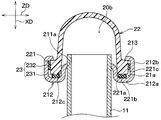
- the core plate 21 of the present embodiment is made of a metal (for example, an aluminum alloy) excellent in thermal conductivity, corrosion resistance, and the like. As shown in FIGS. 3 and 4, the core plate 21 accommodates a tube joint portion 211 that joins the tube 11, and a flange portion 221 and a seal member 23 of the tank main body portion 22 described later around the tube joint portion 211. An annular housing groove 212 is provided.
- the housing groove 212 has three wall surfaces and is formed in a U shape as shown in FIGS. That is, the housing groove 212 is a bottom wall 212a extending in the tube width direction ZD when viewed from the tube stacking direction YD, and an outer wall 212b that is bent in an L shape from the bottom wall 212a and extends in the tube longitudinal direction XD. And an inner wall portion 212c.
- An accommodating space 21a for accommodating the seal member 23 is formed between each of the wall portions 212a to 212c and a facing surface of the flange portion 221 of the tank main body portion 22 described later that faces the core plate 21.
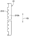
- the outer wall portion 212b is a wall portion erected on the outer peripheral side of the bottom wall portion 212a. Further, the inner wall portion 212c is a wall portion erected on the inner peripheral side of the bottom wall portion 212a. A plurality of caulking protruding pieces 213 are formed at the end of the outer wall 212b of the housing groove 212 as shown in FIG.
- the tube joining portion 211 has a plurality of tube insertion holes 211a for brazing and joining in the state in which the end portions of the tube longitudinal direction XD in each tube 11 are inserted. Are arranged at predetermined intervals.
- the core plate 21 of the present embodiment is configured by connecting the tube joint portion 211 and the inner wall portion 212c of the housing groove portion 212. Thereby, as for the core plate 21, the site
- the tank body 22 of the present embodiment is formed of a resin such as glass reinforced polyamide reinforced with glass fibers.
- a flange portion 221 having a larger thickness than other portions is provided at a tip portion close to the core plate 21.
- the flange portion 221 is formed in a size that can be accommodated in the accommodation groove portion 212.
- the flange portion 221 has a bottom surface 221 a that faces the bottom wall portion 212 a of the housing groove portion 212, and a side surface 221 c that faces the outer wall portion 212 b of the housing groove portion 212.
- the bottom surface 221a of the flange portion 221 of the present embodiment is provided with a protruding portion 221b that protrudes toward the bottom wall portion 212a side of the housing groove portion 212.
- the protrusion 221b is provided to stabilize the position and the like of the first seal portion 231 when pressing a first seal portion 231 of a seal member 23 described later against the bottom wall portion 212a side of the housing groove portion 212.
- the flange portion 221 is configured such that the bottom surface 221a of the flange portion 221 and the bottom wall portion 212a of the accommodation groove portion 212 are separated from each other, and the side surface 221c of the flange portion 221 and the outer wall portion 212b of the accommodation groove portion 212 are separated from each other. 212. Thereby, an accommodation space 21 a for accommodating the seal member 23 is formed between the flange portion 221 and the accommodation groove portion 212.
- the seal member 23 of the present embodiment includes a first seal portion 231 and a second seal portion 232 that are configured by separate members. That is, the first seal portion 231 and the second seal portion 232 are configured separately.
- the seal portions 231 and 232 are formed in an annular shape so as to be accommodated in the accommodation groove portion 212.
- Each of the seal portions 231 and 232 is made of elastically deformable rubber.
- sticker part 231 and 232 by silicon rubber or EPDM (ethylene propylene diene rubber), for example.
- the first seal portion 231 of the present embodiment is provided to seal the tank internal space 20b of the header tanks 20 and 30.
- the first seal portion 231 of the present embodiment is sandwiched between the bottom wall portion 212a of the housing groove portion 212 and the bottom surface 221a of the flange portion 221 in an elastically deformed state.
- the second seal portion 232 of the present embodiment is provided to prevent the corrosive liquid from entering the space between the housing groove portion 212 and the first seal portion 231 from the outside of the radiator 1.
- the first seal portion 231 of the present embodiment is sandwiched between the outer wall portion 212b of the housing groove portion 212 and the side surface 221c of the flange portion 221 in an elastically deformed state.
- each component constituting the radiator 1 is prepared (preparation step).
- This preparation step includes a step of forming the core plate 21 having the tube joint portion 211, the housing groove portion 212, and the protruding piece 213.
- the core portion 10 and the like are provisionally assembled by assembling the tube 11, the fins 12, and the side plate 40 prepared in the preparation process in the tube stacking direction YD on the work table (temporary assembly process).
- the flange part 221 and the seal member 23 of the tank main body part 22 are accommodated in the accommodating groove part 212 of the core plate 21.
- the first seal portion 231 is disposed on the bottom wall portion 212a of the accommodation groove portion 212, and the second seal portion 232 is wound around the side surface 221c of the flange portion 221 in the accommodation groove portion 212.
- the flange portion 221 and the seal member 23 are accommodated.
- the tank main body portion 22 is deformed relative to the core plate 21 by plastically deforming each protruding piece 213 of the core plate 21 by press working or the like. Caulking and fixing.
- the manufacturing of the radiator 1 is completed through inspection processes such as a leakage inspection and a dimension inspection. In the leakage inspection or the like, it is confirmed whether or not there is a brazing defect or a caulking defect at the joint portion of the radiator 1.
- the radiator 1 of the present embodiment described above has the following effects by having the above-described configuration.
- the first seal portion 231 of the seal member 23 is elastically deformed between the bottom wall portion 212a of the housing groove portion 212 of the core plate 21 and the bottom surface 221a of the flange portion 221 of the tank main body portion 22. It is configured to be held in a state. Thereby, the tank internal space 20b of each header tank 20 and 30 can be sealed.
- FIG. 7 shows a configuration in which only the first seal portion 231 of the seal member 23 is disposed between the bottom wall portion 212a of the housing groove portion 212 and the side surface 221c of the flange portion 221 (hereinafter referred to as a comparative example). It is sectional drawing which shows the principal part.
- the first seal portion 231 seals the tank internal space 20b of each of the header tanks 20 and 30, so that leakage of cooling water from the header tanks 20 and 30 is suppressed.
- the corrosive liquid for example, seawater or acid rain
- the second seal portion of the seal member 23 is provided between the outer wall portion 212b of the housing groove portion 212 of the core plate 21 and the side surface 221c of the flange portion 221 of the tank main body portion 22. 232 is sandwiched in an elastically deformed state.
- the gap C between the outer wall portion 212 b of the housing groove portion 212 and the side surface 221 c of the flange portion 221 is closed by the second seal portion 232. For this reason, it can suppress that the liquid which has corrosivity penetrate
- the radiator 1 of the present embodiment it is possible to suppress the leakage of the fluid in the header tanks 20 and 30 by suppressing the corrosion of the core plate 21 due to the corrosive liquid existing outside the radiator 1.
- each seal part 231 and 232 which comprise the seal member 23 are comprised by the separate member. That is, the first seal portion 231 and the second seal portion 232 of the present embodiment are configured separately. According to this, each seal part 231 and 232 can be provided in arbitrary positions, and the freedom degree of design can be ensured.
- the radiator that is mounted on the vehicle and cools the fluid flowing in the tube 11 in the core portion 10 by exchanging heat with the outside air is cooled with the outside air by a corrosive liquid (for example, seawater or acid rain).
- a corrosive liquid for example, seawater or acid rain.
- invasion to the bottom wall part 212a side of the storage groove part 212 of the corrosive liquid with respect to the radiator 1 like this embodiment is suitable for the heat radiator mounted in the vehicle.
- the present embodiment is different from the first embodiment in that the single sealing member 23 is configured to suppress the penetration of the corrosive liquid into the bottom wall 212a side of the storage groove 212.
- a first seal portion 23a and a second seal portion 23b are connected via a connecting portion 23c.
- Each seal part 23a, 23b and the connection part 23c are integrally molded by injection molding or the like. That is, the 1st seal part 23a and the 2nd seal part 23b of this embodiment are comprised integrally.
- the thickness of the connecting portion 23c is larger than the thickness of each of the seal portions 23a and 23b, there is a concern that the gap C between the housing groove portion 212 and the flange portion 221 is sealed at an unintended position. For this reason, it is desirable to make the thickness of the connection part 23c smaller than the thickness of each seal part 23a, 23b.
- the radiator 1 of the present embodiment is configured such that the second seal portion 23b of the seal member 23 is sandwiched between the outer wall portion 212b of the housing groove portion 212 and the side surface 221c of the flange portion 221. For this reason, similarly to the first embodiment, the radiator 1 of the present embodiment suppresses the corrosion of the core plate 21 due to the corrosive liquid existing outside the radiator 1, and leaks the fluid in the header tanks 20 and 30. Can be suppressed.
- the first seal portion 23a and the second seal portion 23b are formed of a single member. That is, the 1st seal part 23a and the 2nd seal part 23b of this embodiment are comprised integrally. For this reason, the radiator 1 which can suppress the corrosion of the core plate 21 by the liquid which has the corrosiveness which exists outside with a simple structure without increasing the number of parts is realizable.
- radiator 1 configured by a downflow type heat exchanger that flows cooling water along the vertical direction
- present invention is not limited thereto.
- the radiator 1 may be configured by, for example, a cross-flow heat exchanger that flows cooling water along the horizontal direction.
- the heat exchanger of the present disclosure may be applied to an outdoor heat exchanger of a refrigeration cycle for a vehicle, or may be applied to a radiator such as a stationary refrigerator used for other than a vehicle.
Landscapes
- Engineering & Computer Science (AREA)
- Physics & Mathematics (AREA)
- Thermal Sciences (AREA)
- Mechanical Engineering (AREA)
- General Engineering & Computer Science (AREA)
- Heat-Exchange Devices With Radiators And Conduit Assemblies (AREA)
Abstract
熱交換器のヘッダタンクは、コアプレート(21)と、タンク本体部(22)と、シール部材(23)と、を有している。コアプレートは、複数のチューブ挿入穴が形成されたチューブ接合部(211)と、チューブ接合部の外側を囲むと共に、タンク本体部の先端部(221)、およびシール部材を収容する環状の収容溝部(212)と、を有している。収容溝部は、タンク本体部の先端部におけるコアプレートに対向する対向面との間にシール部材を収容する収容空間(21a)を形成する底壁部(212a)、および底壁部の外周側に立設された外側壁部(212b)を有している。シール部材は、底壁部とタンク本体部の先端部における底壁部に対向する底面(221a)とで狭持されると共に、外側壁部とタンク本体部の先端部における側壁部と対向する側面(221c)とで狭持されている。
Description
本出願は、2015年8月4日に出願された日本出願番号2015-154434号に基づくものであって、ここにその記載内容を援用する。
本開示は、熱交換器に関するもので、水冷式の内燃機関の冷却水を冷却するラジエータに好適である。
従来、熱交換器は、複数のチューブと複数のコルゲートフィンとを交互に積層して構成されるコア部、チューブにおける長手方向の端部に接合されてチューブに連通するヘッダタンク等を備えている。ヘッダタンクは、チューブが挿入接合されるコアプレート、およびコアプレートに対して端部が固定され、コアプレートと共にヘッダタンクの内部空間を形成するタンク本体部を備えている。コアプレートは、ヘッダタンク内側に平坦面を有すると共に、複数のチューブが挿入されるチューブ挿入穴が設けられたチューブ接合部、チューブ接合部の外側に設けられてタンク本体部の端部を受け入れる溝部が設けられている。
この種の熱交換器では、コアプレートの溝部にシール部材(例えば、ガスケット)を配置し、当該シール部材を溝部の底部とタンク本体部の端部とで狭持する構成が知られている(例えば、特許文献1参照)。これにより、ヘッダタンク内部における封止性の確保を図っている。
ところで、本発明者らは、コアプレートの溝部の底部とタンク本体部の端部とでシール部材を狭持した熱交換器において、ヘッダタンク内部の流体の漏れの有無を調査研究した。この結果、ヘッダタンクにおいて流体の僅かなにじみ漏れが生ずることがあった。
これに対して、にじみ漏れが発生した熱交換器について本発明者らが調査したところ、該当する熱交換器はコアプレートの溝部の底部が腐食していることが判った。そして、この腐食によりコアプレートの溝部の底部とシール部材との間に微小な隙間が形成されることで、ヘッダタンク内部の流体が漏れていることが明らかとなった。
そこで、本発明者らは、ヘッダタンクにおける流体の漏れという課題を解決すべく、コアプレートの溝部の底部の腐食要因について詳細に検討した。この結果、熱交換器の外部に存在する腐食性を有する液体が、コアプレートの溝部とヘッダタンクの端部との間に形成される隙間からコアプレートの溝部の底部に侵入して滞留することが原因であることが判った。
本開示は、外部に存在する腐食性を有する液体によるコアプレートの腐食を抑え、ヘッダタンクにおける流体の漏れを抑制可能な熱交換器を提供することを目的とする。
本開示の1つの観点によれば、熱交換器は、
流体が流通する複数のチューブが積層されたコア部と、
チューブの長手方向の端部に配置され、チューブの積層方向に沿って延びると共に複数のチューブに連通するヘッダタンクと、を備える。
流体が流通する複数のチューブが積層されたコア部と、
チューブの長手方向の端部に配置され、チューブの積層方向に沿って延びると共に複数のチューブに連通するヘッダタンクと、を備える。
ヘッダタンクは、
チューブの長手方向の端部が複数のチューブ挿入穴に挿入された状態で、複数のチューブが接合されたコアプレートと、
コアプレートに固定され、コアプレートと共に複数のチューブに連通するタンク内部空間を形成するタンク本体部と、
タンク本体部とコアプレートとで狭持されるシール部材と、を有している。
チューブの長手方向の端部が複数のチューブ挿入穴に挿入された状態で、複数のチューブが接合されたコアプレートと、
コアプレートに固定され、コアプレートと共に複数のチューブに連通するタンク内部空間を形成するタンク本体部と、
タンク本体部とコアプレートとで狭持されるシール部材と、を有している。
コアプレートは、
複数のチューブ挿入穴が形成されたチューブ接合部と、
チューブ接合部の外側を囲むと共に、タンク本体部の先端部、およびシール部材を収容する環状の収容溝部と、を有している。
複数のチューブ挿入穴が形成されたチューブ接合部と、
チューブ接合部の外側を囲むと共に、タンク本体部の先端部、およびシール部材を収容する環状の収容溝部と、を有している。
収容溝部は、タンク本体部の先端部におけるコアプレートに対向する対向面との間にシール部材を収容する収容空間を形成する底壁部、および底壁部の外周側に立設された外側壁部を有している。
そして、シール部材は、底壁部とタンク本体部の先端部における底壁部に対向する底面とで狭持されると共に、外側壁部とタンク本体部の先端部における側壁部と対向する側面とで狭持されている。
このように、シール部材をコアプレートの収容溝部における底壁部とタンク本体部の先端部における底面とで狭持する構成とすれば、ヘッダタンクにおけるタンク内部空間を封止することができる。
加えて、本開示の熱交換器では、シール部材をコアプレートの収容溝部における外側壁部とタンク本体部の先端部における側面とで狭持する構成としている。このため、熱交換器の外部から腐食性を有する液体がコアプレートの収容溝部の底壁部とシール部材との間に侵入することを抑制することができる。
従って、熱交換器の外部に存在する腐食性を有する液体によるコアプレートの腐食を抑えて、ヘッダタンクにおける流体の漏れを抑制することが可能となる。
以下、本開示の実施形態について図面を参照して説明する。なお、以下の各実施形態において、先行する実施形態で説明した事項と同一もしくは均等である部分には、同一の参照符号を付し、その説明を省略する場合がある。
また、各実施形態において、構成要素の一部だけを説明している場合、構成要素の他の部分に関しては、先行する実施形態において説明した構成要素を適用することができる。
以下の実施形態は、特に組み合わせに支障が生じない範囲であれば、特に明示していない場合であっても、各実施形態同士を部分的に組み合わせることができる。
(第1実施形態)
本実施形態について図1~図8を参照して説明する。本実施形態では、本開示に係る熱交換器を、車両に搭載されて車室外空気(すなわち、外気)との熱交換により冷却対象である流体(例えば、冷却水)を冷却する放熱器に適用している。具体的には、本実施形態では、本開示に係る熱交換器を、車両前方側の空間に配置されて、図示しない水冷式の内燃機関の冷却水を外気と熱交換して冷却するラジエータ1に適用している。
本実施形態について図1~図8を参照して説明する。本実施形態では、本開示に係る熱交換器を、車両に搭載されて車室外空気(すなわち、外気)との熱交換により冷却対象である流体(例えば、冷却水)を冷却する放熱器に適用している。具体的には、本実施形態では、本開示に係る熱交換器を、車両前方側の空間に配置されて、図示しない水冷式の内燃機関の冷却水を外気と熱交換して冷却するラジエータ1に適用している。
まず、本実施形態のラジエータ1の基本構成について図1を参照して説明する。図1に示すように、本実施形態のラジエータ1は、冷却水を上下方向に沿って流すダウンフロー型の熱交換器で構成されている。ラジエータ1は、内燃機関の冷却水を外気と熱交換させる放熱部であるコア部10を有する。コア部10は、チューブ11とフィン12とが水平方向に沿って交互に複数積層配置された積層体で構成されている。以下、本実施形態では、各チューブ11および各フィン12の積層方向をチューブ積層方向YDと呼ぶ。なお、チューブ積層方向YDは、水平方向に沿って延びる方向である。
各チューブ11は、その内部に図示しない内燃機関の冷却水が流通する流路が形成されている。本実施形態の各チューブ11は、その長手方向が上下方向に沿って延びると共に、その断面における長径となる方向が外気の流通方向に沿って延びるように扁平形状に構成されている。
ここで、偏平形状とは、曲率半径の大きい円弧部と曲率半径の小さい円弧部とを結合した曲線形状からなる楕円形状や、円弧部と平坦部とを結合した形状からなる長円形状等を包含するものである。なお、本実施形態では、説明の便宜上、チューブ11の長手方向をチューブ長手方向XDと呼び、チューブ長手方向XDおよびチューブ積層方向YDに直交する方向をチューブ幅方向ZDと呼ぶ。なお、チューブ幅方向ZDは、チューブ11の長径となる方向と一致する方向である。
フィン12は、外気との伝熱面積を増大させて、外気と冷却水との熱交換を促進する部材である。本実施形態のフィン12は、コルゲート状に成形されており、チューブ11の両側の平坦面に対して接合されている。
本実施形態の各チューブ11、およびフィン12それぞれは、熱伝導率、耐食性等に優れた金属(例えば、アルミニウム合金)で構成されている。本実施形態のラジエータ1は、各チューブ11、フィン12、後述するコアプレート21、後述するサイドプレート40が、各部材の所定箇所に被覆されたろう材により一体にろう付け接合されている。
各チューブ11におけるチューブ長手方向XDの両端部には、チューブ積層方向YDに延びると共に、内部に空間が形成された一対のヘッダタンク20、30が配置されている。各ヘッダタンク20、30は、各チューブ11のチューブ長手方向XDの端部が、後述するコアプレート21のチューブ挿入穴211aに挿入された状態で接合されている。そして、各チューブ11における内部通路は、各ヘッダタンク20、30の内部に形成されるタンク内部空間20bに連通している。
一対のヘッダタンク20、30のうち、一方のヘッダタンクは、図示しない内燃機関から流出した高温の冷却水を各チューブ11に分配供給する入口側タンク20を構成している。入口側タンク20には、図示しないホースを介して内燃機関の冷却水の出口側に接続される流入口パイプ20aが設けられている。
一対のヘッダタンク20、30のうち、他方のヘッダタンクは、コア部10において外気との熱交換により冷却された冷却水を集合回収して排出する出口側タンク30を構成している。出口側タンク30には、図示しないホースを介して内燃機関の冷却水の入口側に接続される流出口パイプ30aが設けられている。
コア部10におけるチューブ積層方向YDの両端部には、コア部10を補強するサイドプレート40が配置されている。サイドプレート40は、チューブ長手方向XDに沿って延びており、その両端が各ヘッダタンク20、30に接続されている。本実施形態のサイドプレート40は、アルミニウム合金等の金属で構成されている。
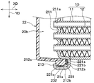
続いて、各ヘッダタンク20、30の詳細な構造について、図2~図6を参照して説明する。図2に示すように、各ヘッダタンク20、30は、チューブ11が挿入された状態で接合されたコアプレート21、コアプレート21と共に各ヘッダタンク20、30のタンク内部空間20bを形成するタンク本体部22、およびシール部材23を有している。
本実施形態では、シール部材23をコアプレート21とタンク本体部22との間に挟んだ状態で、後述するコアプレート21の突出片213をタンク本体部22に押しつけるように塑性変形させてタンク本体部22をコアプレート21にカシメ固定している。
本実施形態のコアプレート21は、熱伝導率、耐食性等に優れた金属(例えば、アルミニウム合金)で構成されている。図3、図4に示すように、コアプレート21は、チューブ11を接合するチューブ接合部211、チューブ接合部211の周囲に、後述するタンク本体部22のフランジ部221およびシール部材23を収容する環状の収容溝部212を有している。
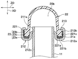
収容溝部212は、図4、図5に示すように、3つの壁面を有し、U字形状に構成されている。すなわち、収容溝部212は、チューブ積層方向YDから見たときに、チューブ幅方向ZDに延びる底壁部212a、底壁部212aからL字状に折り曲げられてチューブ長手方向XDに延びる外側壁部212bおよび内側壁部212cを有している。
各壁部212a~212cと後述するタンク本体部22のフランジ部221におけるコアプレート21に対向する対向面との間には、シール部材23を収容する収容空間21aが形成されている。
外側壁部212bは、底壁部212aの外周側に立設された壁部である。また、内側壁部212cは、底壁部212aの内周側に立設された壁部である。そして、収容溝部212の外側壁部212bの端部には、図3に示すように、カシメ用の複数の突出片213が形成されている。
チューブ接合部211には、図4、図5に示すように、各チューブ11におけるチューブ長手方向XDの端部を挿入した状態でろう付け接合するための複数のチューブ挿入穴211aがチューブ積層方向YDに所定の間隔をあけて並ぶように形成されている。
本実施形態のコアプレート21は、チューブ接合部211と収容溝部212の内側壁部212cとが接続されることで構成されている。これにより、コアプレート21は、チューブ接合部211と収容溝部212の底壁部212aとの間の部位が段付き形状となっている。
続いて、タンク本体部22について説明する。本実施形態のタンク本体部22は、ガラス繊維で強化されたガラス強化ポリアミド等の樹脂で形成されている。本実施形態のタンク本体部22には、コアプレート21に近接する先端部に他の部位よりも厚みが大きいフランジ部221が設けられている。
フランジ部221は、収容溝部212に収容可能な大きさに形成されている。フランジ部221は、収容溝部212の底壁部212aに対向する底面221a、収容溝部212の外側壁部212bに対向する側面221cを有している。
本実施形態のフランジ部221の底面221aには、収容溝部212の底壁部212a側に向かって突出する突起部221bが設けられている。この突起部221bは、後述するシール部材23の第1シール部231を収容溝部212の底壁部212a側に押し付ける際に、第1シール部231の位置等を安定させるために設けられている。
フランジ部221は、フランジ部221の底面221aと収容溝部212の底壁部212aとが離間すると共に、フランジ部221の側面221cと収容溝部212の外側壁部212bとが離間した状態で、収容溝部212に収容されている。これにより、フランジ部221と収容溝部212との間には、シール部材23を収容する収容空間21aが形成されている。
続いて、シール部材23について説明する。本実施形態のシール部材23は、別部材で構成された第1シール部231および第2シール部232を有している。すなわち、第1シール部231および第2シール部232は、別体で構成されている。
各シール部231、232は、収容溝部212に収容可能なように環状に形成されている。各シール部231、232は、弾性変形可能なゴムで構成されている。なお、各シール部231、232は、例えば、シリコンゴムや、EPDM(エチレン・プロピレン・ジエンゴム)で形成すればよい。
本実施形態の第1シール部231は、ヘッダタンク20、30のタンク内部空間20bを封止するために設けられている。本実施形態の第1シール部231は、収容溝部212の底壁部212aとフランジ部221の底面221aとの間に、弾性変形した状態で狭持されている。
本実施形態の第2シール部232は、ラジエータ1の外部から腐食性を有する液体が、収容溝部212と第1シール部231との間に侵入することを抑えるために設けられている。本実施形態の第1シール部231は、収容溝部212の外側壁部212bとフランジ部221の側面221cとの間に、弾性変形した状態で狭持されている。
次に、上記構成を備えるラジエータ1の製造方法の概略について説明する。最初の工程では、ラジエータ1を構成する各部品を用意する(用意工程)。この用意工程には、チューブ接合部211、収容溝部212、突出片213を有するコアプレート21を成形する工程が含まれる。
続く工程では、用意工程で用意したチューブ11、フィン12、サイドプレート40を作業台上で、チューブ積層方向YDに組み付けることにより、コア部10等を仮組みする(仮組工程)。
続く工程では、チューブ挿入穴211aが形成されたコアプレート21をコア部10に組付けた後、ワイヤ等の治具により組付けた状態を保持する。さらに、本工程では、コアプレート21をコア部10に組付けた状態の組付体を、加熱された炉内に置くことで、コアプレート21、コア部10の各要素をろう付けにより接合する(ろう付け接合工程)。
ろう付け接合工程の終了後の工程では、コアプレート21の収容溝部212に、タンク本体部22のフランジ部221およびシール部材23を収容する。具体的には、本工程では、第1シール部231を収容溝部212の底壁部212aに配置すると共に、第2シール部232をフランジ部221の側面221cに巻き付けた状態で、収容溝部212にフランジ部221およびシール部材23を収容する。
続く工程では、収容溝部212にフランジ部221およびシール部材23を収容した状態で、コアプレート21の各突出片213をプレス加工等により塑性変形させることで、コアプレート21に対してタンク本体部22をかしめ固定する。
続いて、漏れ検査、および寸法検査等を行う検査工程を経てラジエータ1の製造が完了する。なお、漏れ検査等では、ラジエータ1の各部品の接合箇所にろう付け不良やかしめ不良等が生じていないかを確認する。
以上説明した本実施形態のラジエータ1は、上述の構成を備えることで、以下の効果を奏する。本実施形態のラジエータ1は、コアプレート21の収容溝部212の底壁部212aとタンク本体部22のフランジ部221の底面221aとの間に、シール部材23の第1シール部231を弾性変形した状態で狭持する構成となっている。これにより、各ヘッダタンク20、30のタンク内部空間20bを封止することができる。
ここで、図7は、収容溝部212の底壁部212aとフランジ部221の側面221cとの間に、シール部材23の第1シール部231だけを配置した構成(以下、比較例と呼ぶ。)の要部を示す断面図である。
比較例に係る構成では、第1シール部231により、各ヘッダタンク20、30のタンク内部空間20bが封止されることで、ヘッダタンク20、30からの冷却水の漏れが抑えられる。
しかしながら、比較例に係る構成では、外部から腐食性を有する液体(例えば、海水や酸性の雨)が、図7の矢印で示すように、収容溝部212の外側壁部212bとフランジ部221の側面221cとの隙間Cから収容溝部212の底壁部212a側に侵入する。
そして、腐食性を有する液体が収容溝部212の底壁部212aに滞留すると、底壁部212aにおける第1シール部231と接する部位が腐食する。この腐食により、底壁部212aと第1シール部231との間に微小な隙間が形成されることで、ヘッダタンク20、30から冷却水が僅かに漏れてしまうことがある。
これに対して、本実施形態のラジエータ1は、コアプレート21の収容溝部212の外側壁部212bとタンク本体部22のフランジ部221の側面221cとの間に、シール部材23の第2シール部232を弾性変形した状態で狭持する構成となっている。
これによれば、図8に示すように、収容溝部212の外側壁部212bとフランジ部221の側面221cとの隙間Cが第2シール部232により閉塞される。このため、腐食性を有する液体が、収容溝部212の外側壁部212bとフランジ部221の側面221cとの隙間Cから収容溝部212の底壁部212a側へ侵入してしまうことを抑えることができる。
従って、本実施形態のラジエータ1によれば、ラジエータ1の外部に存在する腐食性を有する液体によるコアプレート21の腐食を抑えて、ヘッダタンク20、30における流体の漏れを抑制することができる。
また、本実施形態では、シール部材23を構成する各シール部231、232を別部材で構成している。すなわち、本実施形態の第1シール部231および第2シール部232は別体で構成されている。これによれば、各シール部231、232を任意の位置に設けることができ、設計の自由度を確保することができる。
ここで、車両に搭載されて、コア部10にてチューブ11内を流れる流体を外気と熱交換させて冷却する放熱器は、外気と共に腐食性を有する液体(例えば、海水や酸性の雨)が流入し易い。このため、本実施形態の如く、ラジエータ1に対して、腐食性を有する液体の収容溝部212の底壁部212a側への侵入を抑える構造は、車両に搭載された放熱器に好適である。
(第2実施形態)
次に、第2実施形態について、図9、図10を参照して説明する。本実施形態では、単一のシール部材23により、腐食性を有する液体の収容溝部212の底壁部212a側への侵入を抑える構成としている点が第1実施形態と相違している。
次に、第2実施形態について、図9、図10を参照して説明する。本実施形態では、単一のシール部材23により、腐食性を有する液体の収容溝部212の底壁部212a側への侵入を抑える構成としている点が第1実施形態と相違している。
図9に示すように、本実施形態のシール部材23は、第1シール部23aと第2シール部23bとが連結部23cを介して接続されている。各シール部23a、23bおよび連結部23cは、射出成形等により一体に成形されている。すなわち、本実施形態の第1シール部23aおよび第2シール部23bは、一体で構成されている。
ここで、連結部23cの厚みが、各シール部23a、23bの厚みよりも大きいと、収容溝部212とフランジ部221との隙間Cが意図しない位置でシールされてしまうことが懸念される。このため、連結部23cの厚みは、各シール部23a、23bの厚みよりも小さくすることが望ましい。
その他の構成は、第1実施形態と同様である。本実施形態のラジエータ1は、収容溝部212の外側壁部212bとフランジ部221の側面221cとの間に、シール部材23の第2シール部23bを狭持する構成となっている。このため、本実施形態のラジエータ1は、第1実施形態と同様に、ラジエータ1の外部に存在する腐食性を有する液体によるコアプレート21の腐食を抑えて、ヘッダタンク20、30における流体の漏れを抑制することができる。
また、本実施形態では、第1シール部23aおよび第2シール部23bを単一の部材で構成している。すなわち、本実施形態の第1シール部23aおよび第2シール部23bは、一体で構成されている。このため、部品点数を増加させることなく、簡素な構成で、外部に存在する腐食性を有する液体によるコアプレート21の腐食を抑えることが可能なラジエータ1を実現することができる。
(他の実施形態)
以上、本開示の実施形態について説明したが、本開示は上述の実施形態に限定されるものではなく、適宜変更が可能である。本開示の熱交換器は、例えば、以下のように種々変形可能である。
以上、本開示の実施形態について説明したが、本開示は上述の実施形態に限定されるものではなく、適宜変更が可能である。本開示の熱交換器は、例えば、以下のように種々変形可能である。
上述の各実施形態では、ラジエータ1を、冷却水を上下方向に沿って流すダウンフロー型の熱交換器で構成する例について説明したが、これに限定されない。ラジエータ1は、例えば、冷却水を水平方向に沿って流すクロスフロー型の熱交換器で構成されていてもよい。
上述の各実施形態では、本開示の熱交換器を車両用のラジエータ1に適用する例について説明したが、これに限定されない。本開示の熱交換器は、車両用の冷凍サイクルの室外熱交換器に適用したり、車両以外に用いられる定置置の冷凍機等の放熱器に適用したりしてもよい。
上述の実施形態において、実施形態を構成する要素は、特に必須であると明示した場合および原理的に明らかに必須であると考えられる場合等を除き、必ずしも必須のものではないことは言うまでもない。
上述の実施形態において、実施形態の構成要素の個数、数値、量、範囲等の数値が言及されている場合、特に必須であると明示した場合および原理的に明らかに特定の数に限定される場合等を除き、その特定の数に限定されない。
上述の実施形態において、構成要素等の形状、位置関係等に言及するときは、特に明示した場合および原理的に特定の形状、位置関係等に限定される場合等を除き、その形状、位置関係等に限定されない。
Claims (4)
- 熱交換器であって、
流体が流通する複数のチューブ(11)が積層されたコア部(10)と、
前記チューブの長手方向の端部に配置され、前記チューブの積層方向に沿って延びると共に前記複数のチューブに連通するヘッダタンク(20、30)と、を備え、
前記ヘッダタンクは、
前記チューブの長手方向の端部が複数のチューブ挿入穴(211a)に挿入された状態で、前記複数のチューブが接合されたコアプレート(21)と、
前記コアプレートに固定され、前記コアプレートと共に前記複数のチューブに連通するタンク内部空間(20b)を形成するタンク本体部(22)と、
前記タンク本体部と前記コアプレートとで狭持されるシール部材(23)と、を有しており、
前記コアプレートは、
前記複数のチューブ挿入穴が形成されたチューブ接合部(211)と、
前記チューブ接合部の外側を囲むと共に、前記タンク本体部の先端部(221)、および前記シール部材を収容する環状の収容溝部(212)と、を有しており、
前記収容溝部は、前記タンク本体部の先端部における前記コアプレートに対向する対向面との間に前記シール部材を収容する収容空間(21a)を形成する底壁部(212a)、および前記底壁部の外周側に立設された外側壁部(212b)を有しており、
前記シール部材は、前記底壁部と前記タンク本体部の先端部における前記底壁部に対向する底面(221a)とで狭持されると共に、前記外側壁部と前記タンク本体部の先端部における前記側壁部と対向する側面(221c)とで狭持されている熱交換器。 - 前記シール部材は、
前記底壁部と前記タンク本体部の先端部における前記底壁部に対向する底面とで狭持される第1シール部(231)と、
前記側壁部と前記タンク本体部の先端部における前記側壁部と対向する側面とで狭持される第2シール部(232)と、を有しており、
前記第1シール部および前記第2シール部は、別体で構成されている請求項1に記載の熱交換器。 - 前記シール部材は、
前記底壁部と前記タンク本体部の先端部における前記底壁部に対向する底面とで狭持される第1シール部(23a)と、
前記側壁部と前記タンク本体部の先端部における前記側壁部と対向する側面とで狭持される第2シール部(23b)と、を有しており、
前記第1シール部および前記第2シール部は、一体で構成されている請求項1に記載の熱交換器。 - 車両に搭載された放熱器を構成しており、
前記コア部は、前記複数のチューブの内部を流れる流体を車室外空気と熱交換させて冷却する放熱部を構成している請求項1ないし3のいずれか1つに記載の熱交換器。
Applications Claiming Priority (2)
| Application Number | Priority Date | Filing Date | Title |
|---|---|---|---|
| JP2015-154434 | 2015-08-04 | ||
| JP2015154434A JP2018151075A (ja) | 2015-08-04 | 2015-08-04 | 熱交換器 |
Publications (1)
| Publication Number | Publication Date |
|---|---|
| WO2017022399A1 true WO2017022399A1 (ja) | 2017-02-09 |
Family
ID=57942808
Family Applications (1)
| Application Number | Title | Priority Date | Filing Date |
|---|---|---|---|
| PCT/JP2016/070132 Ceased WO2017022399A1 (ja) | 2015-08-04 | 2016-07-07 | 熱交換器 |
Country Status (2)
| Country | Link |
|---|---|
| JP (1) | JP2018151075A (ja) |
| WO (1) | WO2017022399A1 (ja) |
Cited By (2)
| Publication number | Priority date | Publication date | Assignee | Title |
|---|---|---|---|---|
| JPWO2017026210A1 (ja) * | 2015-08-07 | 2018-02-08 | 株式会社デンソー | 熱交換器 |
| WO2019220059A1 (fr) * | 2018-05-18 | 2019-11-21 | Valeo Systemes Thermiques | Echangeur de chaleur comprenant un joint principal d'étanchéité et un joint secondaire d'étanchéité |
Citations (7)
| Publication number | Priority date | Publication date | Assignee | Title |
|---|---|---|---|---|
| JPS58168896A (ja) * | 1982-03-31 | 1983-10-05 | Nippon Denso Co Ltd | 熱交換器 |
| JPS6016892U (ja) * | 1983-07-08 | 1985-02-05 | トヨタ自動車株式会社 | ラジエ−タ |
| JPS61170889U (ja) * | 1985-04-08 | 1986-10-23 | ||
| JPH07318286A (ja) * | 1994-05-20 | 1995-12-08 | Calsonic Corp | 熱交換器のシール構造 |
| US5979546A (en) * | 1998-04-02 | 1999-11-09 | Carlisle Engineered Products | Joint for a heat exchanger assembly |
| US20020029874A1 (en) * | 2000-02-10 | 2002-03-14 | Patrick Boisselle | Heat exchanger with improved sealing gasket, for a motor vehicle in particular |
| JP2009257657A (ja) * | 2008-04-15 | 2009-11-05 | Denso Corp | 熱交換器および熱交換器の製造方法 |
-
2015
- 2015-08-04 JP JP2015154434A patent/JP2018151075A/ja active Pending
-
2016
- 2016-07-07 WO PCT/JP2016/070132 patent/WO2017022399A1/ja not_active Ceased
Patent Citations (7)
| Publication number | Priority date | Publication date | Assignee | Title |
|---|---|---|---|---|
| JPS58168896A (ja) * | 1982-03-31 | 1983-10-05 | Nippon Denso Co Ltd | 熱交換器 |
| JPS6016892U (ja) * | 1983-07-08 | 1985-02-05 | トヨタ自動車株式会社 | ラジエ−タ |
| JPS61170889U (ja) * | 1985-04-08 | 1986-10-23 | ||
| JPH07318286A (ja) * | 1994-05-20 | 1995-12-08 | Calsonic Corp | 熱交換器のシール構造 |
| US5979546A (en) * | 1998-04-02 | 1999-11-09 | Carlisle Engineered Products | Joint for a heat exchanger assembly |
| US20020029874A1 (en) * | 2000-02-10 | 2002-03-14 | Patrick Boisselle | Heat exchanger with improved sealing gasket, for a motor vehicle in particular |
| JP2009257657A (ja) * | 2008-04-15 | 2009-11-05 | Denso Corp | 熱交換器および熱交換器の製造方法 |
Cited By (3)
| Publication number | Priority date | Publication date | Assignee | Title |
|---|---|---|---|---|
| JPWO2017026210A1 (ja) * | 2015-08-07 | 2018-02-08 | 株式会社デンソー | 熱交換器 |
| WO2019220059A1 (fr) * | 2018-05-18 | 2019-11-21 | Valeo Systemes Thermiques | Echangeur de chaleur comprenant un joint principal d'étanchéité et un joint secondaire d'étanchéité |
| FR3081216A1 (fr) * | 2018-05-18 | 2019-11-22 | Valeo Systemes Thermiques | Echangeur de chaleur comprenant un joint principal d’etancheite et un joint secondaire d’etancheite |
Also Published As
| Publication number | Publication date |
|---|---|
| JP2018151075A (ja) | 2018-09-27 |
Similar Documents
| Publication | Publication Date | Title |
|---|---|---|
| CN108139183B (zh) | 热交换器 | |
| CN105793663B (zh) | 热交换器 | |
| JP5598565B2 (ja) | 熱交換器 | |
| JP2011099631A (ja) | 熱交換器 | |
| US10401095B2 (en) | Heat exchanger | |
| WO2013094149A1 (ja) | 排気熱交換装置 | |
| US10962309B2 (en) | Stacked heat exchanger | |
| US20170301610A1 (en) | Cooler module, and method for manufacturing cooler module | |
| WO2017013918A1 (ja) | 熱交換器 | |
| JP6365781B2 (ja) | 熱交換器 | |
| KR20120053786A (ko) | 라디에이터 | |
| WO2017022399A1 (ja) | 熱交換器 | |
| JP2009216151A (ja) | シール構造およびそれを用いた熱交換器 | |
| JP2015206507A (ja) | 熱交換器 | |
| JPH04268199A (ja) | 熱交換器 | |
| JP2019090573A (ja) | 熱交換器およびその製造方法 | |
| JP2012159211A (ja) | 熱交換器 | |
| JP6459776B2 (ja) | 継手接続部のシール構造およびその製造方法 | |
| US20060048930A1 (en) | Heat exchanger | |
| JP6384344B2 (ja) | 熱交換器 | |
| KR100662243B1 (ko) | 자동차용 오일쿨러 | |
| JP7290030B2 (ja) | 熱交換器 | |
| KR100676650B1 (ko) | 자동차용 오일쿨러 | |
| JP6992581B2 (ja) | 熱交換器 | |
| KR101884311B1 (ko) | 라디에이터 |
Legal Events
| Date | Code | Title | Description |
|---|---|---|---|
| 121 | Ep: the epo has been informed by wipo that ep was designated in this application |
Ref document number: 16832678 Country of ref document: EP Kind code of ref document: A1 |
|
| NENP | Non-entry into the national phase |
Ref country code: DE |
|
| 122 | Ep: pct application non-entry in european phase |
Ref document number: 16832678 Country of ref document: EP Kind code of ref document: A1 |
|
| NENP | Non-entry into the national phase |
Ref country code: JP |