WO2017022007A1 - 回転電機ユニット - Google Patents
回転電機ユニット Download PDFInfo
- Publication number
- WO2017022007A1 WO2017022007A1 PCT/JP2015/071772 JP2015071772W WO2017022007A1 WO 2017022007 A1 WO2017022007 A1 WO 2017022007A1 JP 2015071772 W JP2015071772 W JP 2015071772W WO 2017022007 A1 WO2017022007 A1 WO 2017022007A1
- Authority
- WO
- WIPO (PCT)
- Prior art keywords
- electrical machine
- rotating electrical
- axial direction
- control unit
- stator
- Prior art date
- Legal status (The legal status is an assumption and is not a legal conclusion. Google has not performed a legal analysis and makes no representation as to the accuracy of the status listed.)
- Ceased
Links
Images





Classifications
-
- H—ELECTRICITY
- H02—GENERATION; CONVERSION OR DISTRIBUTION OF ELECTRIC POWER
- H02K—DYNAMO-ELECTRIC MACHINES
- H02K7/00—Arrangements for handling mechanical energy structurally associated with dynamo-electric machines, e.g. structural association with mechanical driving motors or auxiliary dynamo-electric machines
- H02K7/18—Structural association of electric generators with mechanical driving motors, e.g. with turbines
-
- H—ELECTRICITY
- H02—GENERATION; CONVERSION OR DISTRIBUTION OF ELECTRIC POWER
- H02K—DYNAMO-ELECTRIC MACHINES
- H02K9/00—Arrangements for cooling or ventilating
- H02K9/02—Arrangements for cooling or ventilating by ambient air flowing through the machine
-
- H—ELECTRICITY
- H02—GENERATION; CONVERSION OR DISTRIBUTION OF ELECTRIC POWER
- H02K—DYNAMO-ELECTRIC MACHINES
- H02K9/00—Arrangements for cooling or ventilating
- H02K9/02—Arrangements for cooling or ventilating by ambient air flowing through the machine
- H02K9/04—Arrangements for cooling or ventilating by ambient air flowing through the machine having means for generating a flow of cooling medium
- H02K9/06—Arrangements for cooling or ventilating by ambient air flowing through the machine having means for generating a flow of cooling medium with fans or impellers driven by the machine shaft
Definitions
- the present invention relates to a rotating electrical machine unit.
- a rotation shaft (for example, a crankshaft) of an engine provided in a vehicle or the like is connected to a starter motor that rotationally drives the rotation shaft of the engine with electric power or a rotating electrical machine that constitutes a generator that generates electric power by rotation of the rotation shaft of the engine. ing.
- the operation of this type of rotating electrical machine is controlled by a control unit. For example, when the engine is started by the rotating electrical machine, electric power is supplied from the control unit to the rotating electrical machine. Further, when power is generated in the rotating electrical machine, electric power is supplied from the rotating electrical machine to the control unit.
- Patent Document 1 discloses a configuration in which a control unit is arranged in an engine room so that the influence of heat generated in the engine and hot air due to self-heating of the control unit can be suppressed.
- the wiring connecting the control unit and the rotating electrical machine becomes long and the voltage loss in the wiring becomes large. is there.
- the electric power generated in the rotating electrical machine is wasted until the power reaches the control unit, and the actual power generation amount is reduced.
- An object of one aspect of the present invention is to provide a rotating electrical machine unit that can suppress voltage loss between the rotating electrical machine and a control unit and can efficiently cool the control unit.
- a rotating electrical machine unit includes a stator and a rotor that is rotatably provided with respect to the stator and rotates together with a rotating shaft of an engine, and constitutes at least one of a starter motor and a generator.
- a rotating electric machine a control unit configured to control the operation of the rotating electric machine, and a blade portion in which a plurality of blades are arranged in a circumferential direction, and rotating the rotating shaft together with the air
- a centrifugal fan configured to flow from the inside to the outside, wherein the control unit, the rotating electrical machine, and the centrifugal fan are sequentially arranged in the axial direction of the rotating shaft, and the rotating electrical machine has an inner circumference thereof
- a ventilation passage section for flowing air from one side of the rotating electrical machine to the other side in the axial direction in accordance with the rotation of the centrifugal fan. Knit is arranged so as to overlap with the ventilation passage portion in a plan view.
- the centrifugal fan rotates, so that air flows in the vicinity of the control unit and the ventilation passage portion in the inner peripheral portion of the rotating electrical machine in order, Flows from inside to outside. Since air flows in the vicinity of the control unit, the control unit can be actively cooled. Further, since the control unit is actively cooled, the influence of the engine heat received by the control unit can be suppressed, so that the control unit can be disposed near the engine together with the rotating electrical machine. Therefore, the wiring connecting the rotating electrical machine and the control unit can be shortened, and voltage loss between the rotating electrical machine and the control unit can be suppressed. Thereby, the electric power generation amount in a rotary electric machine can be increased, or an engine can be started efficiently with small power consumption. Further, since the rotational driving force of the centrifugal fan can be obtained from the engine or the rotating electrical machine, it is not necessary to separately prepare a driving source for driving the centrifugal fan, and the control unit can be efficiently cooled.
- the rotating electrical machine unit 1 includes a rotating electrical machine 2, a control unit 3, and a centrifugal fan 4.
- the rotating electrical machine 2 of the present embodiment is configured as a starter motor that rotationally drives a rotating shaft 102 (for example, a crankshaft) of the engine 100 with electric power.
- the rotating electrical machine 2 is configured as a generator that generates power by the rotation of the rotating shaft 102 of the engine 100.
- the rotation shaft 102 of the engine 100 is rotatably attached to the main body 101 of the engine 100. An end of the rotating shaft 102 in the axial direction (vertical direction in FIG. 1) protrudes from the main body 101.
- the rotating electrical machine 2 includes a stator 11 and a rotor 12 provided to be rotatable with respect to the stator 11.
- the rotor 12 rotates with the rotating shaft 102 of the engine 100 with respect to the stator 11.
- the rotor 12 may be connected to the rotating shaft 102 via, for example, an endless belt or a gear (both not shown), but in this embodiment, the axis of the rotor 12 (the rotating electrical machine 2) is the axis L1 of the rotating shaft 102. Is attached to the rotating shaft 102 so as to coincide with.
- the stator 11 includes a stator base portion 13 and a plurality of coils 14 attached to the stator base portion 13.
- the stator base portion 13 includes a plurality of teeth portions (not shown) arranged in the circumferential direction of the rotating shaft 102 (hereinafter also simply referred to as the circumferential direction).
- the plurality of coils 14 are wound around each tooth portion. That is, the plurality of coils 14 are arranged in the circumferential direction of the rotating shaft 102.
- the rotor 12 includes a rotor base portion 15 and a plurality of permanent magnets 16 fixed to the rotor base portion.
- the plurality of permanent magnets 16 are arranged in the circumferential direction so as to face the plurality of coils 14 described above.
- the rotating electrical machine 2 may be, for example, a radial gap rotating electrical machine in which the stator 11 and the rotor 12 are arranged to face each other in the radial direction of the rotating shaft 102 (hereinafter also simply referred to as the radial direction).
- the rotating electrical machine 2 of the embodiment is an axial gap type rotating electrical machine that is disposed so that the stator 11 and the rotor 12 face each other in the axial direction of the rotating shaft 102 (hereinafter also simply referred to as the axial direction).
- the rotating electrical machine 2 of the present embodiment will be described more specifically.
- the stator base portion 13 includes a base plate portion 21 formed in a plate shape having a circular shape in plan view when viewed from the axial direction.
- the plurality of coils 14 are provided on one main surface 22 of the base plate portion 21 and are arranged in the circumferential direction of the base plate portion 21. Thereby, the plurality of coils 14 are formed in a cylindrical shape as a whole.
- a plurality of through holes 23 and 24 penetrating in the thickness direction of the base plate portion 21 are formed in a portion of the base plate portion 21 in a plan view on the inner peripheral side of the plurality of coils 14.
- the first through hole 23 is formed in a circular shape in plan view with the axis of the base plate portion 21 as the center.
- a plurality of second through holes 24 are formed around the first through hole 23 in plan view.
- the planar view shape of the plurality of through holes 23 and 24 may be arbitrary, in the present embodiment, it is circular.
- the rotor base portion 15 is formed in a circular plate shape in plan view.
- the plurality of permanent magnets 16 are fixed to one main surface 25 of the rotor base portion 15 facing the one main surface 22 of the base plate portion 21 described above.
- the plurality of permanent magnets 16 are arranged in the circumferential direction of the rotor base portion 15.
- the magnetic poles of the plurality of permanent magnets 16 facing the base plate portion 21 side of the stator 11 alternately appear in the circumferential direction of the rotor base portion 15.
- the stator 11 and the rotor 12 are arranged at intervals so that the plurality of coils 14 and the plurality of permanent magnets 16 face each other in the axial direction of the rotating shaft 102.
- a plurality of through holes 26 and 27 penetrating in the thickness direction of the rotor base portion 15 are formed in a portion of the rotor base portion 15 in a plan view on the inner peripheral side of the plurality of permanent magnets 16.
- the third through hole 26 is formed in a circular shape in plan view with the axis of the rotor base portion 15 as the center.
- a plurality of fourth through holes 27 are formed around the third through hole 26 in plan view.
- the shape of the fourth through hole 27 in plan view may be arbitrary, but in the present embodiment, it is an arc shape.
- the rotating electrical machine 2 of the present embodiment further includes a connecting shaft portion 17 that rotatably connects the stator 11 and the rotor 12 to each other.
- the connecting shaft portion 17 fixes the relative position between the stator 11 and the rotor 12 in the axial direction of the rotating shaft 102.
- the connecting shaft portion 17 includes a shaft portion main body 31 and a bearing portion 32.
- the shaft body 31 is formed to extend in the axial direction of the rotating shaft 102 and is inserted into the first through hole 23 of the stator base portion 13 and the third through hole 26 of the rotor base portion 15.
- the shaft body 31 may be fixed to the stator base 13, for example, but is fixed to the rotor base 15 in this embodiment.
- a flange portion 33 for fixing the shaft portion main body 31 to the rotor base portion 15 is formed at a first end portion in the axial direction of the shaft portion main body 31.
- the portion between the third through hole 26 and the plurality of fourth through holes 27 in the rotor base portion 15 through which the shaft main body 31 is inserted comes into contact with the flange portion 33.
- a method for fixing the rotor base portion 15 and the flange portion 33 may be arbitrary, such as screwing. In a state where the rotor base portion 15 and the flange portion 33 are fixed, the axes of the rotor 12 and the connecting shaft portion 17 coincide.
- the bearing portion 32 enables the stator 11 and the rotor 12 connected by the connecting shaft portion 17 to rotate relative to each other.
- the bearing portion 32 is a radial bearing such as a ball bearing or a roller bearing.
- the bearing portion 32 may be provided, for example, between the outer periphery of the shaft portion main body 31 and the third through hole 26 of the rotor base portion 15, but in the present embodiment, the outer periphery of the shaft portion main body 31 and the stator base portion 13.
- the first through hole 23 is provided.
- the bearing portion 32 is fixed in the first through hole 23 of the stator base portion 13. Further, the bearing portion 32 is positioned at the second end portion in the axial direction of the shaft body 31. More specifically, a locking surface 34 facing the axial direction of the shaft body 31 is formed at the second end of the shaft body 31.
- the bearing portion 32 and the stator base portion 13 fixed to the bearing portion 32 are positioned at the second end portion of the shaft portion main body 31 by the inner peripheral portion of the bearing portion 32 coming into contact with the locking surface 34 of the shaft portion main body 31. . That is, the connecting shaft portion 17 has an axial distance between the stator base portion 13 and the rotor base portion 15, more specifically, the coil 14 of the stator 11 and the rotor 12 by the flange portion 33 and the locking surface 34. A gap (gap) with the permanent magnet 16 is set.
- the rotor 12 may be directly fixed to the rotating shaft 102 of the engine 100, but in the present embodiment, the rotor 12 is fixed to the rotating shaft 102 via the connecting shaft portion 17.
- the connecting shaft portion 17 of the present embodiment is provided with a fixing portion 35 for fixing it to the rotating shaft 102 of the engine 100.
- the fixed portion 35 may be provided at the second end portion (stator 11 side) of the shaft portion main body 31, but in the present embodiment, the fixed portion 35 is provided at the first end portion (rotor 12 side) of the shaft portion main body 31. . For this reason, in a state where the rotor 12 is fixed to the rotating shaft 102, the rotor 12 and the stator 11 are arranged in this order from the engine 100 side. In the present embodiment, the fixed portion 35 protrudes from the rotor base portion 15 to the outside of the rotating electrical machine 2 in the axial direction of the shaft portion main body 31.
- the fixed portion 35 includes a bottomed insertion hole 37 that is recessed from the first end surface 36 facing the axial direction of the shaft body 31 at the first end of the shaft body 31, and the rotation shaft 102 that is inserted into the insertion hole 37.
- the insertion hole 37 is formed so that the end of the rotating shaft 102 fits.
- the screw 38 may be attached to the shaft main body 31 so as to protrude into the insertion hole 37 from at least the inner surface of the insertion hole 37 and screwed to the end of the rotating shaft 102 inserted into the insertion hole 37.
- the screw 38 is attached to the shaft portion main body 31 so as to protrude in the axial direction of the shaft portion main body 31 from the bottom surface of the insertion hole 37.
- the end of the rotating shaft 102 can be fixed to the shaft body 31.
- the axis of the connecting shaft portion 17 coincides with the axis L1 of the rotating shaft 102.
- the axis of the rotating electrical machine 2 coincides with the axis L1 of the rotating shaft 102.
- the rotating electrical machine 2 described above has an air flow passage section 40 that flows air from one side of the rotating electrical machine 2 to the other side in the axial direction of the rotating shaft 102 in accordance with the rotation of the centrifugal fan 4 to be described later on the inner periphery thereof.
- the one side and the other side of the rotating electrical machine 2 mean a space on one side and a space on the other side of the rotating electrical machine 2, respectively.
- the ventilation flow path portion 40 includes a plurality of second through holes 24 of the stator base portion 13 and a space on the inner peripheral side of the plurality of coils 14 arranged in the circumferential direction (hereinafter referred to as an inner peripheral space 29). And a plurality of fourth through holes 27 of the rotor base portion 15.
- Inner circumferential spaces 29 of the plurality of coils 14 are located between the stator base portion 13 and the rotor base portion 15 in the axial direction of the rotating shaft 102.
- the inner circumferential space 29 communicates with one side of the rotating electrical machine 2 through the plurality of second through holes 24. Further, the inner circumferential space 29 communicates with the other side of the rotating electrical machine 2 through a plurality of fourth through holes 27.
- the stator base portion 13 and the plurality of coils 14 are arranged such that the plurality of second through holes 24 and the inner circumferential space 29 overlap when viewed from the axial direction.
- stator 11 particularly the plurality of coils 14
- rotor 12 particularly the rotor base portion 15
- the stator 11 and the rotor 12 are arranged such that the inner circumferential space 29 and the plurality of fourth through holes 27 overlap each other when viewed from the axial direction.
- air can flow from one side of the rotating electrical machine 2 to the other side of the rotating electrical machine 2 through the plurality of second through holes 24, the inner peripheral space 29, and the plurality of fourth through holes 27.
- the ventilation channel portion 40 further includes an in-shaft channel 41 formed in the connecting shaft portion 17.
- the in-shaft channel 41 allows air to flow into the inside of the connecting shaft portion 17 from the end surface (second end surface 39 described later) of the connecting shaft portion 17 located at one end of the rotating electrical machine 2 in the axial direction of the rotating shaft 102. In the axial direction, it is allowed to flow outward from the outer peripheral surface of the connecting shaft portion 17 at a position shifted from the one end of the rotating electrical machine 2 toward the other end of the rotating electrical machine 2.
- the in-shaft channel 41 of the present embodiment will be specifically described.
- the in-shaft channel 41 includes an axial hole 42 that extends in the axial direction of the shaft body 31 and a radial hole 43 that extends in the radial direction of the shaft body 31.
- the axial hole 42 is a bottomed hole that opens in the second end surface 39 of the shaft main body 31 facing the axial direction of the shaft main body 31 at the second end of the shaft main body 31 corresponding to one end of the rotating electrical machine 2. It is.
- the radial hole 43 penetrates from the inner peripheral surface of the shaft main body 31 constituting the axial hole 42 to the outer peripheral surface of the shaft main body 31 at the bottom of the axial hole 42.
- the radial hole portion 43 opens to the outer peripheral side of the shaft portion main body 31 between the rotor base portion 15 and the base plate portion 21 of the stator base portion 13.
- the radial hole 43 communicates the axial hole 42 and the inner circumferential space 29 of the plurality of coils 14.
- a plurality of radial holes 43 may be arranged in the circumferential direction of the shaft body 31, but only one is formed in this embodiment.
- the control unit 3 is configured to be electrically connected to the rotating electrical machine 2 by wiring (not shown) and to control the operation of the rotating electrical machine 2.
- the control unit 3 controls the power supplied to the rotating electrical machine 2 when the rotating electrical machine 2 functions as a starter motor, for example.
- the control unit 3 appropriately adjusts the voltage and current of the power generated by the rotating electrical machine 2 and then charges the generated power to a battery (not shown). Or directly supplied to various electrical components (not shown).
- the external shape of the control unit 3 may be arbitrary, but in the present embodiment, it is formed in a thick disk shape.
- the control unit 3 includes a control circuit unit 51 for controlling the operation of the rotating electrical machine 2 and a case 52 that houses the control circuit unit 51.
- the control unit 3 further includes a sealing resin 53 that seals the control circuit unit 51 in the case 52.
- the control unit 3 further includes terminals (not shown) such as connectors for electrically connecting the control circuit unit 51 to the rotating electrical machine 2, the battery, and various electrical components.
- the control circuit unit 51 of this embodiment includes a substrate 54 and an electronic component 55 mounted on the substrate 54. 1 and 2, only one electronic component 55 is mounted on the substrate 54, but a plurality of electronic components 55 of various sizes and types may be mounted, for example.
- the electronic component 55 shown in FIGS. 1 and 2 is a heat source of the control unit 3 that mainly generates heat when controlling the operation of the rotating electrical machine 2.
- the case 52 makes the appearance of the control unit 3.
- the case 52 opens to one side of the control unit 3 in the thickness direction.
- the case 52 of the present embodiment includes a plate-like bottom wall portion 56 and a cylindrical peripheral wall portion 57 that extends in the thickness direction of the bottom wall portion 56 at the periphery of the bottom wall portion 56.
- An electronic component 55 as a heat source is disposed near the opening of the case 52.
- the centrifugal fan 4 is provided so as to rotate together with the rotating shaft 102 of the engine 100, similarly to the rotor 12 described above.
- the centrifugal fan 4 has a blade portion 62 in which a plurality of blades 61 are arranged in the circumferential direction.
- the centrifugal fan 4 is configured to flow air from the inside to the outside of the blade portion 62 in the radial direction by rotating about its axis.
- the centrifugal fan 4 of the present embodiment is a sirocco fan and has a cylindrical appearance.
- the control unit 3, the rotating electrical machine 2, and the centrifugal fan 4 are sequentially arranged in the axial direction of the rotating shaft 102.
- the control unit 3 is disposed on one side of the rotating electrical machine 2 in the axial direction of the rotating shaft 102. That is, the control unit 3 is disposed so as to face the stator base portion 13 of the rotating electrical machine 2 in the axial direction of the rotating shaft 102.
- the control unit 3 is disposed so as to overlap the ventilation flow path portion 40 of the rotating electrical machine 2 in a plan view as viewed from the axial direction of the rotating shaft 102.
- the control unit 3 is arranged with an interval in the axial direction of the rotating shaft 102 with respect to the rotating electrical machine 2.
- control unit 3 is arranged such that the opening of the case 52 faces the stator base portion 13. For this reason, the electronic component 55 as a heat source is disposed in a portion of the control unit 3 that faces the rotating electrical machine 2.
- the centrifugal fan 4 is disposed on the other side of the rotating electrical machine 2 in the axial direction of the rotating shaft 102. That is, the centrifugal fan 4 is arranged so as to face the rotor base portion 15 of the rotating electrical machine 2 in the axial direction of the rotating shaft 102.
- the centrifugal fan 4 is located inward of the blade portion 62 in the radial direction of the blade portion 62 in which the ventilation passage portion 40 of the rotating electrical machine 2 is cylindrical in a plan view as viewed from the axial direction of the rotating shaft 102. Arranged.
- the centrifugal fan 4 may be connected to the rotating shaft 102 via, for example, an endless belt or a gear (both not shown), or directly fixed to the rotating shaft 102.
- the centrifugal fan 4 is connected via the rotor 12. And fixed to the rotating shaft 102 of the engine 100. That is, the centrifugal fan 4 is fixed to the rotor 12.
- the centrifugal fan 4 is disposed at the first end portion in the axial direction of the cylindrical blade portion 62, and is located on the inner side of the blade portion 62 in the radial direction.
- An extending annular plate portion 63 is provided.
- the annular plate portion 63 is arranged so as to overlap the rotor base portion 15 in the plate thickness direction so as not to block the plurality of fourth through holes 27.
- the annular plate portion 63 is fixed to the rotor base portion 15 by screwing or the like. Thereby, the centrifugal fan 4 is fixed to the rotor 12.
- the centrifugal fan 4 In a state where the centrifugal fan 4 is fixed to the rotor 12, the axes of the centrifugal fan 4 and the rotor 12 coincide with each other. In this state, the fixed portion 35 of the connecting shaft portion 17 is disposed inside the centrifugal fan 4. For this reason, in this embodiment, the engine 100 is arranged on the second end side of the blade portion 62 with respect to the centrifugal fan 4.
- the rotating electrical machine unit 1 of the present embodiment further includes a mounting portion 70 for attaching the stator 11 of the rotating electrical machine 2 to the main body 101 of the engine 100.
- the attachment portion 70 may attach the stator 11 to the main body portion 101 so as not to move, but in the present embodiment, the stator 11 is attached to the main body portion 101 so as to be movable only in the axial direction of the rotary shaft 102.
- the rotating electrical machine unit 1 further includes a pair of urging portions 71 and 71 that are arranged on both sides of the stator 11 in the axial direction of the rotating shaft 102 and urge the stator in the axial direction with respect to the mounting portion 70. .
- the mounting portion 70 of the present embodiment is formed in a ring shape in plan view and supports a stator 11, and extends from the support portion 72 in the axial direction of the rotary shaft 102 to the main body of the engine 100. And an extension part 73 that reaches the part 101.
- the support portion 72 is arranged with a gap on both sides in the axial direction with respect to the stator 11, and a pair of limiting wall portions 74 and 74 that limit the movement range of the stator 11 in the axial direction to a predetermined range, and a radial direction And a connecting wall portion 75 that is disposed outside the stator 11 and connects the pair of limiting wall portions 74 and 74.
- an outer peripheral edge portion that is positioned outside the plurality of coils 14 in the radial direction in the base plate portion 21 of the stator 11 is disposed.
- a plurality of the pair of limiting wall portions 74 and 74 may be provided, for example, at intervals in the circumferential direction of the stator 11, but are formed in a ring shape in plan view in the present embodiment. For this reason, the entire circumferential direction of the outer peripheral edge portion of the base plate portion 21 is disposed between the pair of limiting wall portions 74 and 74.
- a pin (not shown) extending in the axial direction is provided between the pair of limiting wall portions 74, 74.
- the pins may be inserted through the outer peripheral edge of the base plate portion 21.
- the extension part 73 is formed integrally with the support part 72 described above.
- the extending portion 73 is disposed outside the rotating electrical machine 2 and the centrifugal fan 4 in the radial direction.
- the extending portion 73 may be configured by a plurality of rod-like members arranged at intervals in the circumferential direction, for example, but in the present embodiment, a cylindrical shape that surrounds the rotating electrical machine 2 and the centrifugal fan 4 in the radial direction. Is formed. That is, the mounting portion 70 of the present embodiment functions as a cylindrical case 52 that houses the rotating electrical machine 2 and the centrifugal fan 4.
- the extending portion 73 of the present embodiment is formed with a ventilation through hole 76 for flowing the air that flows out of the blade portion 62 in accordance with the rotation of the centrifugal fan 4 in a predetermined direction.
- the ventilation through-hole 76 is formed through the extending portion 73 in the radial direction at a portion of the extending portion 73 that faces the outside of the blade portion 62.
- the ventilation through hole 76 is formed in a part of the extending portion 73 in the circumferential direction. In the illustrated example, only one ventilation through hole 76 is formed. However, a plurality of through holes 76 may be formed, for example.
- the distal end portion of the extending portion 73 in the extending direction is fixed to the surface of the main body 101 of the engine 100 from which the rotating shaft 102 protrudes (attachment surface 104) by screwing or the like.
- attachment surface 104 attachment surface 104
- the stator 11 is attached to the main body 101 of the engine 100 via the attachment portion 70. In a state where the stator 11 is attached to the main body 101, the stator 11 can be prevented from rotating together with the rotor 12.
- the pair of urging portions 71 and 71 are respectively disposed between the outer peripheral edge portion of the base plate portion 21 and the limiting wall portion 74.
- a plurality of pairs of urging portions 71 and 71 are arranged at intervals in the circumferential direction of the base plate portion 21.
- the stator 11 is arranged in a stable state between the pair of limiting wall portions 74 and 74 by the biasing force of the pair of biasing portions 71 and 71.
- the urging portion 71 may be a coil spring as shown in the figure, or may be a leaf spring or rubber, for example.
- the control unit 3 may be fixed to the stator 11 of the rotating electrical machine 2, for example, but is fixed to the mounting portion 70 in the present embodiment.
- the control unit 3 is fixed to a support portion 72 formed in a ring shape in plan view via a spacer 77.
- a plurality of spacers 77 are arranged at intervals in the circumferential direction of the support portion 72.
- a part or the whole of the configuration in which the rotating electrical machine unit 1 is attached to the engine 100 is covered with the engine cover 103.
- the engine cover 103 has a predetermined part of the engine 100 (for example, a combustion chamber of the engine 100) as shown by an arrow F8 in FIG. It is formed to flow toward the vicinity.
- the rotating electrical machine unit 1 of the present embodiment is attached to the engine 100 so that the ventilation through hole 76 of the attachment portion 70 described above faces the engine cover 103.
- the centrifugal fan 4 rotates by obtaining driving force from the engine 100 or the rotating electrical machine 2
- air is present in the vicinity of the control unit 3 and in the inner periphery of the rotating electrical machine 2.
- the air flows from the inside to the outside of the blade 62.
- the air that has entered the gap between the rotating electrical machine 2 and the control unit 3 flows into the ventilation passage section 40 of the rotating electrical machine 2 from one side of the rotating electrical machine 2 as shown by arrows F2 and F3 in FIG. Flowing.
- a part of the air that has entered the gap between the rotating electrical machine 2 and the control unit 3 passes from the plurality of second through holes 24 of the stator base portion 13 to a plurality of coils as indicated by an arrow F2 in FIG. 14 enters the inner circumferential space 29 and flows in the axial direction toward the rotor base portion 15.
- the remaining part of the air that has entered the gap between the rotating electrical machine 2 and the control unit 3 enters the in-shaft channel 41 of the connecting shaft 17 as shown by an arrow F3 in FIG. Flows in the axial direction toward the 15 side. Air flowing through the shaft inner flow channel 41 flows from the inner side to the outer shaft flow channel 41 through the radial hole 43 of the shaft inner flow channel 41 as indicated by an arrow F4 in FIG. 14 in the inner circumferential space 29. The air flow indicated by the arrow F4 merges with the air flow indicated by the arrow F2 in the inner circumferential space 29 of the coil 14.
- the air flow merged in the inner circumferential space 29 flows in the axial direction as shown by an arrow F5 in FIG. 1 and flows out to the other side of the rotating electrical machine 2 through the fourth through hole 27 of the rotor base portion 15. It enters the inside of the centrifugal fan 4 (blade part 62).
- the air that has entered the inside of the centrifugal fan 4 (blade part 62) flows from the inside to the outside of the blade part 62 as indicated by an arrow F6 in FIG.
- the air that has flowed outside the blade portion 62 passes through the ventilation through hole 76 formed in the cylindrical extension portion 73 surrounding the outside of the blade portion 62, as shown by an arrow F7 in FIG. Flows out of the outside.
- the air that has flowed to the outside of the extending portion 73 flows toward a predetermined portion of the engine 100 by the engine cover 103 as indicated by an arrow F8 in FIG.
- the rotating electrical machine unit 1 of the present embodiment since the air flows in the vicinity of the control unit 3 as the centrifugal fan 4 rotates, the control unit 3 is actively cooled. For this reason, it becomes possible to suppress the influence of the heat of the engine 100 which the control unit 3 receives, and the control unit 3 can be disposed near the engine 100 together with the rotating electrical machine 2. Accordingly, the wiring connecting the rotating electrical machine 2 and the control unit 3 can be shortened, and voltage loss between the rotating electrical machine 2 and the control unit 3 can be suppressed. Thereby, the electric power generation amount in the rotary electric machine 2 can be increased, or the engine 100 can be started efficiently with small power consumption. Further, since the rotational driving force of the centrifugal fan 4 is obtained from the engine 100 or the rotating electrical machine 2, it is not necessary to separately prepare a drive source for driving the centrifugal fan 4, and the control unit 3 can be efficiently cooled.
- the centrifugal fan 4 is arranged between the control unit 3 and the engine 100, so that air that flows in the vicinity of the control unit 3 flows from the control unit 3 toward the engine 100 side. For this reason, the influence of the heat of the engine 100 which the control unit 3 receives can be suppressed effectively.
- the rotating electrical machine unit 1 of the present embodiment since the rotating electrical machine 2 is an axial gap type rotating electrical machine, the dimension (thickness dimension) of the rotating electrical machine 2 in the axial direction is smaller than that of the radial gap type rotating electrical machine. Can be set small. Therefore, the rotating electrical machine unit 1 can be thinned.
- the stator 11 and the rotor 12 that form an axial gap type rotating electrical machine are connected by the connecting shaft portion 17.
- the gap (gap) between the stator 11 and the rotor 12 in the axial direction can be set in advance by the connecting shaft portion 17.
- the gap between the stator 11 and the rotor 12 can be easily set narrow, and the performance of the rotating electrical machine 2 can be easily improved.
- the ventilation flow path portion 40 of the rotating electrical machine 2 includes the in-shaft channel 41 formed in the connecting shaft portion 17. For this reason, even if the rotary electric machine 2 is configured by connecting the stator 11 and the rotor 12 by the connecting shaft portion 17, the flow passage cross section of the ventilation flow passage portion 40 orthogonal to the axial direction can be set large. Therefore, more air can flow from the control unit 3 side to the centrifugal fan 4 side, and the control unit 3 can be efficiently cooled.
- the rotor 12 of the rotating electrical machine 2 is attached to the end of the rotating shaft 102 of the engine 100 via the connecting shaft portion 17.
- the stator 11 of the rotating electrical machine 2 is attached to the main body portion 101 of the engine 100 by the attachment portion 70 so as to be movable only in the axial direction. For this reason, even when the protruding length of the rotating shaft 102 protruding from the main body 101 of the engine 100 varies, the rotating electric machine 2 moves in the axial direction of the rotating shaft 102 with respect to the main body 101 when the rotating electric machine 2 is attached. By moving, the rotating electrical machine 2 can be stably attached to the engine 100.
- the pair of urging portions 71 and 71 are arranged on both sides of the stator 11 in the axial direction, and urge the stator 11 in the axial direction with respect to the mounting portion 70. For this reason, the axial position of the stator 11 (the rotating electrical machine 2) relative to the mounting portion 70 and the main body portion 101 of the engine 100 can be stabilized by the biasing force of the pair of biasing portions 71 and 71.
- the rotating electrical machine 2 and the control unit 3 are arranged with an interval in the axial direction. For this reason, the opposing part which opposes the rotary electric machine 2 among the control units 3 can be cooled especially efficiently.
- the electronic component 55 as a heat generation source is disposed at a portion facing the control unit 3, the electronic component 55 can be efficiently cooled.
- the centrifugal fan 4 and the rotor 12 are coaxially arranged. For this reason, both the centrifugal fan 4 and the rotor 12 can be directly connected to the rotating shaft 102 of the engine 100 without an endless belt or gear. That is, the number of component parts of the rotating electrical machine unit 1 can be set small.
- the ventilation through hole 76 is formed only in a part in the circumferential direction of the mounting portion 70 surrounding the outside of the blade portion 62 in the radial direction. For this reason, the air flowing out of the rotating centrifugal fan 4 can be made to flow in a desired direction as indicated by an arrow F7 in FIG. As a result, all the air that has flowed out of the attachment portion 70 from the ventilation through hole 76 can flow to a predetermined portion of the engine 100 as indicated by an arrow F8 in FIG. It can be cooled efficiently.
- the rotating electrical machine unit 1A includes the rotating electrical machine 2A, the control unit 3, and the centrifugal fan 4 as in the first embodiment.
- the configurations of the control unit 3 and the centrifugal fan 4 are the same as in the first embodiment.
- the rotating electrical machine 2A of the present embodiment is an axial gap type rotating electrical machine similar to the first embodiment, and includes a stator 11 and a rotor 12A.
- the rotor 12A of this embodiment includes a rotor base portion 15A formed in a plate shape having a circular shape in plan view, and a plurality of permanent magnets fixed to one main surface 25 of the rotor base portion 15A. 16.
- the fifth through hole 27A of the rotor base portion 15A is formed in a circular shape in plan view with the axis of the rotor base portion 15A as the center.
- the size of the fifth through hole 27A in plan view is larger than the third and fourth through holes 26 and 27 (see FIG. 4) formed in the rotor base portion 15A of the first embodiment.
- the fifth through hole 27A of the rotor base portion 15A is formed in a size including the entire formation region of the third and fourth through holes 26 and 27 in the rotor base portion 15A of the first embodiment.
- a ventilation flow path portion 40A for flowing air from one side to the other side is configured.
- the shaft part main body 31A of the connecting shaft part 17A which will be described later, is inserted into the fifth through hole 27A of the rotor base part 15A, the shaft part main body of the fifth through hole 27A of the rotor base part 15A.
- a portion excluding the insertion portion of 31A functions as the ventilation passage portion 40A.
- the centrifugal fan 4 and the rotor 12A are integrally fixed via a reinforcing frame 80A.
- the reinforcing frame 80A may be formed, for example, in the same shape as the rotor base portion 15A of the first embodiment, but is formed in a different shape in the present embodiment.
- the reinforcing frame 80A of the present embodiment includes an annular portion 81A formed in a plate shape with an annular shape in plan view, a cylindrical portion 82A extending from the inner edge of the annular portion 81A to one side in the thickness direction of the annular portion 81A, and a cylinder A plate-like lid portion 83A that closes one end of the portion 82A in the axial direction.
- the cylindrical portion 82A is formed with a flow hole 84A penetrating in the thickness direction. Thereby, air can be flowed from the inner side to the outer side of the cylindrical portion 82A in the radial direction.
- a circulation hole 84A may be formed in a part in the circumferential direction of the cylindrical portion 82A, but in the present embodiment, a plurality of circulation holes 84A are formed at intervals in the circumferential direction of the cylindrical portion 82A.
- the cylindrical portion 82A is inclined so as to move away from the annular portion 81A in the radial direction in the radial direction as it goes in the thickness direction of the annular portion 81A.
- the cylindrical portion 82A is parallel to the thickness direction of the annular portion 81A. And may extend.
- the lid portion 83A is formed with an insertion hole 85A penetrating in the plate thickness direction.
- the shaft portion main body 31A of the connecting shaft portion 17A described later is inserted through the insertion hole 85A.
- the annular portion 81A is disposed between the annular plate portion 63 of the centrifugal fan 4 and the rotor base portion 15A in the axial direction.
- the rotor 12A, the reinforcing frame 80A, and the centrifugal fan 4 are integrated with each other by fixing the rotor base portion 15A, the annular portion 81A, and the annular plate portion 63 in order in the plate thickness direction and then fixing them together by screws or the like. Fixed to. In a state where the rotor 12A, the reinforcing frame 80A, and the centrifugal fan 4 are fixed, the axes of the rotor 12A, the reinforcing frame 80A, and the centrifugal fan 4 coincide.
- the cylindrical portion 82 ⁇ / b> A and the lid portion 83 ⁇ / b> A are inserted into the blade portion 62 from the first end portion of the blade portion 62 of the centrifugal fan 4.
- the length of the cylindrical portion 82A in the axial direction may be longer than the axial length of the centrifugal fan 4, for example, but is shorter than the axial length of the centrifugal fan 4 in this embodiment. For this reason, the cylindrical portion 82 ⁇ / b> A and the lid portion 83 ⁇ / b> A are arranged inside the blade portion 62.
- the rotating electrical machine 2A of the present embodiment includes a connecting shaft portion 17A similar to that of the first embodiment.
- the connecting shaft portion 17A of the present embodiment includes a shaft portion main body 31A and a bearing portion 32 similar to those of the first embodiment.
- the flange portion 33A formed at the first axial end portion of the shaft portion main body 31A is for fixing the shaft portion main body 31A to the reinforcing frame 80A.
- the flange portion 33A contacts the lid portion 83A of the reinforcing frame 80A inserted through the shaft portion main body 31A.
- the method of fixing the reinforcing frame 80A and the flange portion 33A may be arbitrary, such as screwing.
- the in-shaft channel 41 of the connecting shaft portion 17A constituting the ventilation channel portion 40A includes the axial hole portion 42 and the radial hole portion 43 similar to those in the first embodiment.
- the radial hole 43 communicates the axial hole 42 and the inner space 86A of the cylindrical portion 82A of the reinforcing frame 80A. That is, the radial hole portion 43 is located inside the blade portion 62 of the centrifugal fan 4. Further, the radial hole portion 43 is arranged to face at least one of the plurality of flow holes 84A of the cylindrical portion 82A in the radial direction.
- the centrifugal fan 4 rotates by obtaining a driving force from the engine 100 or the rotating electrical machine 2A
- air is supplied to the vicinity of the control unit 3 and to the inner peripheral portion of the rotating electrical machine 2A. After flowing in order through a certain air flow path portion 40A, the air flows from the inside to the outside of the blade portion 62.
- the air flow indicated by arrows F1, F2, F3, F6, F7, and F8 in FIG. It is the same as the form.
- the air flowing through the shaft inner passage 41 passes from the inside of the shaft inner passage 41 by passing through the radial hole 43 of the shaft inner passage 41 as indicated by an arrow F4A in FIG. It flows to the outside and enters the inner space 86A of the cylindrical portion 82A disposed inside the centrifugal fan 4.
- the air that has entered the inner circumferential space 29 of the coil 14 from the plurality of second through holes 24 of the stator base portion 13 passes through the fifth through holes 27A of the rotor base portion 15A as indicated by an arrow F5A in FIG.
- the air flow indicated by the arrow F5A merges with the air flow indicated by the arrow F4A flowing from the in-shaft flow path 41 to the inner space 86A of the cylindrical portion 82A and passes through the flow hole 84A of the cylindrical portion 82A. Flows outward.
- the air that flows out of the cylindrical portion 82A flows from the inside to the outside of the blade portion 62 as shown by an arrow F6 in FIG. 6 without greatly changing the flow direction.
- the same effects as those of the first embodiment can be obtained.
- the centrifugal fan 4 and the rotor 12A are integrally fixed via the reinforcing frame 80A.
- the reinforcing frame 80 ⁇ / b> A can be interposed between the centrifugal fan 4 and the rotor 12 ⁇ / b> A and the rotating shaft 102.
- the stress applied to the centrifugal fan 4 and the rotor 12A as the rotating shaft 102 rotates can be reduced.
- the rigidity of the centrifugal fan 4 can be improved.
- the rotating electrical machine unit 1A of the present embodiment compared to the rotating electrical machine unit 1 of the first embodiment, the number of times the air flow direction changes greatly is reduced, and the air resistance can be reduced. That is, air can be efficiently flowed from one side of the rotating electrical machine 2A to the other side.
- the fixed portion 35 of the connecting shaft portion 17A protrudes in the axial direction from the centrifugal fan 4 and is disposed outside the centrifugal fan 4.
- the centrifugal fan 4 blade part 62.
- the rotating electrical machine unit 1B includes the rotating electrical machine 2A, the control unit 3B, and the centrifugal fan 4 as in the first and second embodiments.
- the configuration of the centrifugal fan 4 is the same as in the first and second embodiments.
- the configuration of the rotating electrical machine 2A is the same as that of the second embodiment.
- the control unit 3B controls the operation of the rotating electrical machine 2A as in the first embodiment.
- the external shape of the control unit 3B of this embodiment is a cylindrical shape unlike the first and second embodiments. That is, the control unit 3B of the present embodiment includes a unit channel portion 50B penetrating in the axial direction. As the centrifugal fan 4 rotates, air flows from one side of the control unit 3B to the other side in the axial direction of the rotary shaft 102 through the unit flow path 50B.
- the unit flow path part 50B is arranged so as to overlap with the ventilation flow path part 40A of the rotating electrical machine 2A in the axial direction of the rotary shaft 102.
- control unit 3B of the present embodiment includes a control circuit unit 51B for controlling the operation of the rotating electrical machine 2A and a case 52B for housing the same, as in the first and second embodiments. And a sealing resin 53 for sealing the control circuit portion 51B in the case 52B.
- the control circuit unit 51B includes the same substrate 54B and electronic component 55B as those in the first and second embodiments.
- the shape of the substrate 54B is different from that of the first and second embodiments, and is formed in, for example, an annular shape in plan view.
- the case 52B opens to one side in the thickness direction of the control unit 3B, as in the first embodiment.
- the case 52B of the present embodiment includes an annular bottom wall portion 56B formed in a plate shape having a ring shape in plan view, and an outer peripheral wall portion extending in the thickness direction of the annular bottom wall portion 56B at the outer peripheral edge of the annular bottom wall portion 56B.
- 57B and an inner peripheral wall portion 58B extending in the thickness direction of the annular bottom wall portion 56B at the inner peripheral edge of the annular bottom wall portion 56B.
- the inner peripheral wall portion 58B is disposed inside the outer peripheral wall portion 57B in the radial direction.
- the accommodation space of the control circuit part 51B in the case 52B is a space between the inner peripheral wall part 58B and the outer peripheral wall part 57B.
- the unit channel portion 50B of the control unit 3B is a space inside the inner peripheral wall portion 58B in the radial direction.
- the electronic component 55B as a heat source is arranged in the vicinity of the inner peripheral wall portion 58B.
- the control unit 3B described above is disposed on one side of the rotating electrical machine 2A so that the axial direction of the unit flow path portion 50B is parallel to the axial direction of the rotary shaft 102. Thereby, the unit flow path part 50B overlaps with the ventilation flow path part 40A and the axial direction of the rotating shaft 102.
- the rotating electrical machine unit 1B shown in FIG. 9 when viewed from the axial direction, only the in-shaft channel 41 of the ventilation channel 40A is located inside the unit channel 50B, and the other ventilation channels 40A
- the portion (for example, the second through hole 24 of the stator base portion 13) is located outside the unit flow path portion 50B, but is not limited thereto.
- control unit 3B may be arranged so as to overlap the rotating electric machine 2A without any gap, but in the present embodiment, the control unit 3B is arranged with an interval in the axial direction of the rotating shaft 102 with respect to the rotating electric machine 2A.
- control unit 3B is directly fixed to the support portion 72 of the attachment portion 70 so as to block one opening of the attachment portion 70 formed in a cylindrical shape.
- the ventilation flow path portion 40A of the rotating electrical machine 2A communicates with the external space only through the unit flow path portion 50B of the control unit 3B. In this configuration, when the centrifugal fan 4 rotates, the air in the external space flows through the unit channel portion 50B of the control unit 3B toward the ventilation channel portion 40A.
- the centrifugal fan 4 rotates by obtaining a driving force from the engine 100 or the rotating electrical machine 2A
- the air flows from the external space (one side of the control unit 3B) to the unit flow path of the control unit 3B as shown by an arrow F1B in FIG. It flows into the part 50B and flows in the axial direction. Thereby, air flows along the inner peripheral part (inner peripheral wall part 58B) of the control unit 3B. That is, air flows in the vicinity of the inner periphery of the control unit 3B. The air that has flowed into the unit channel portion 50B flows out to the other side of the control unit 3B.
- the air that has flowed out to the other side of the control unit 3B flows from one side of the rotating electrical machine 2A into the ventilation passage portion 40A of the rotating electrical machine 2A and flows in the axial direction.
- the air flow indicated by the arrow F ⁇ b> 2 ⁇ / b> B is a flow that enters the inner circumferential spaces 29 of the plurality of coils 14 from the plurality of second through holes 24 of the stator base portion 13.
- the air flow indicated by the arrow F3B is a flow that enters the in-shaft channel 41 of the connecting shaft portion 17A.
- the air flow after entering the ventilation flow path section 40A of the rotating electrical machine 2A is the same as that of the second embodiment.
- the same effects as those of the first and second embodiments can be obtained. Furthermore, according to the rotating electrical machine unit 1B of the present embodiment, the unit flow path portion 50B of the control unit 3B and the ventilation flow path portion 40A of the rotating electrical machine 2A are arranged in the axial direction of the rotating shaft 102. For this reason, air can be smoothly flowed from the control unit 3B toward the rotating electrical machine 2A without largely changing the air flow direction. Thereby, the flow velocity of the air flowing in the vicinity of the control unit 3B can be improved, and the control unit 3B can be efficiently cooled.
- the electronic component 55 as a heat source is disposed on the inner peripheral portion of the control unit 3B that defines the unit flow path portion 50B. Thereby, this electronic component 55 can be efficiently cooled.
- the control unit 3B includes the unit flow path portion 50B.
- interval of the rotary electric machine 2A and control unit 3B can be made small or can be eliminated.
- the axial dimension of the rotating electrical machine unit 1B can be reduced, and the rotating electrical machine unit 1B can be reduced in size and thickness.
- the configuration of the rotating electrical machine unit 1B of the third embodiment is also applicable to the rotating electrical machine unit 1 of the first embodiment.
- the rotating electrical machine unit 1 of the first embodiment may include the same control unit 3B as that of the third embodiment.
- the control unit 3B may be arranged so as to overlap the rotating electrical machine 2 without a gap, for example, or directly fixed to the support portion 72 of the mounting portion 70, for example. May be.
- the control unit 3B may be fixed to the support portion 72 of the attachment portion 70 via the spacer 77, for example, as in the first and second embodiments.
- the ventilation flow path portion 40A of the rotating electrical machine 2A is external space via both the gap between the rotating electrical machine 2A and the support section 72 and the control unit 3B in the axial direction and the unit flow path portion 50B of the control unit 3B. Communicate with.
- the centrifugal fan may be, for example, a turbo fan.
- the air that flows out of the centrifugal fan cools the main body of the engine.
- a radiator for cooling the engine by water cooling may be cooled.
- the rotating electrical machine may constitute, for example, only a starter motor or only a generator.
Landscapes
- Engineering & Computer Science (AREA)
- Power Engineering (AREA)
- Motor Or Generator Cooling System (AREA)
Abstract
回転電機ユニットは、ステータ、及び、ステータに対して回転自在に設けられるロータを有する回転電機と、回転電機の動作を制御するコントロールユニットと、複数の羽根を周方向に配列した羽根部を有し、ロータと共に回転することで空気を羽根部の内側から外側に流す遠心ファンと、を備える。コントロールユニット、回転電機及び遠心ファンは、軸方向に順番に配列される。回転電機は、その内周部に、軸方向において前記回転電機の一方側から他方側に空気を流す通風流路部を有する。コントロールユニットは、平面視で通風流路部と重なる。
Description
この発明は、回転電機ユニットに関する。
車両等に設けられるエンジンの回転軸(例えばクランクシャフト)には、エンジンの回転軸を電力によって回転駆動するスタータモータや、エンジンの回転軸の回転によって発電する発電機を構成する回転電機が接続されている。この種の回転電機の動作は、コントロールユニットによって制御される。例えば、回転電機によってエンジンを始動する際には、コントロールユニットから回転電機に電力が供給される。また、回転電機において発電する際には、回転電機からコントロールユニットに電力が供給される。
一般に、コントロールユニットは熱に弱い電子部品を有する。このため、従来では、回転電機はエンジンの近くに配されるが、コントロールユニットはエンジンから離れた位置に配される。
特許文献1には、エンジンにおいて生じる熱やコントロールユニットの自己発熱による熱気の影響を抑制できるように、エンジンルーム内にコントロールユニットを配置する構成が開示されている。
特許文献1には、エンジンにおいて生じる熱やコントロールユニットの自己発熱による熱気の影響を抑制できるように、エンジンルーム内にコントロールユニットを配置する構成が開示されている。
ところで、従来のようにコントロールユニットが回転電機から離れた位置に配されると、コントロールユニットと回転電機とを接続する配線が長くなってしまい、配線における電圧損失が大きくなってしまう、という問題がある。例えば、回転電機によってエンジンを始動する際には、電力をより高い電圧でコントロールユニットから回転電機に供給する必要があるため、エンジンの始動に要する消費電力が大きくなってしまう。また、回転電機において発電された電力が、コントロールユニットに到達するまでに無駄に消費され、実質的な発電量が減少してしまう。
一方、上記配線を短くするためには、コントロールユニットも回転電機と同様にエンジンの近くに配する必要があるが、この場合には、コントロールユニットを積極的に冷却する必要がある。
一方、上記配線を短くするためには、コントロールユニットも回転電機と同様にエンジンの近くに配する必要があるが、この場合には、コントロールユニットを積極的に冷却する必要がある。
本発明の一態様は、回転電機とコントロールユニットとの間における電圧損失を抑制できると共に、コントロールユニットを効率よく冷却することが可能な回転電機ユニットを提供することを目的とする。
本発明の一態様としての回転電機ユニットは、ステータ、及び、該ステータに対して回転自在に設けられてエンジンの回転軸と共に回転するロータを有し、スタータモータ及び発電機の少なくとも一方を構成する回転電機と、前記回転電機の動作を制御するように構成されたコントロールユニットと、複数の羽根を周方向に配列した羽根部を有し、前記回転軸と共に回転することで空気を前記羽根部の内側から外側に流すように構成された遠心ファンと、を備え、前記コントロールユニット、前記回転電機及び前記遠心ファンが、前記回転軸の軸方向に順番に配列され、前記回転電機は、その内周部に、前記遠心ファンの回転に伴って、前記軸方向において前記回転電機の一方側から他方側に空気を流す通風流路部を有し、前記コントロールユニットが、平面視で前記通風流路部と重なるように配される。
本発明の一態様によれば、遠心ファンが回転することで、空気がコントロールユニットの近傍と、回転電機の内周部にある通風流路部と、を順番に流れた上で、羽根部の内側から外側に流れる。コントロールユニットの近傍に空気が流れることで、コントロールユニットを積極的に冷却することができる。また、コントロールユニットが積極的に冷却されることで、コントロールユニットが受けるエンジンの熱の影響を抑制できるため、コントロールユニットを回転電機と共にエンジンの近くに配置することができる。したがって、回転電機とコントロールユニットとを接続する配線を短くして、回転電機とコントロールユニットとの間における電圧損失を抑制することができる。これにより、回転電機における発電量を増加したり、小さい消費電力で効率よくエンジンを始動したり、することができる。
また、遠心ファンの回転駆動力は、エンジンあるいは回転電機から得ることができるため、遠心ファンを駆動する駆動源を別途用意する必要がなく、コントロールユニットを効率よく冷却することができる。
また、遠心ファンの回転駆動力は、エンジンあるいは回転電機から得ることができるため、遠心ファンを駆動する駆動源を別途用意する必要がなく、コントロールユニットを効率よく冷却することができる。
〔第一実施形態〕
以下、図1~5を参照して本発明の第一実施形態について説明する。
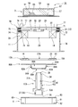
図1,2に示すように、本実施形態に係る回転電機ユニット1は、回転電機2、コントロールユニット3及び遠心ファン4を備える。
以下、図1~5を参照して本発明の第一実施形態について説明する。
図1,2に示すように、本実施形態に係る回転電機ユニット1は、回転電機2、コントロールユニット3及び遠心ファン4を備える。
本実施形態の回転電機2は、エンジン100の回転軸102(例えばクランクシャフト)を電力によって回転駆動するスタータモータとして構成される。また、回転電機2は、エンジン100の回転軸102の回転によって発電する発電機として構成される。エンジン100の回転軸102は、エンジン100の本体部101に対して回転自在に取り付けられる。回転軸102の軸方向(図1において上下方向)の端部は、本体部101から突出する。
回転電機2は、ステータ11、及び、ステータ11に対して回転自在に設けられるロータ12を備える。ロータ12は、ステータ11に対してエンジン100の回転軸102と共に回転する。ロータ12は、例えば無端ベルトやギヤ(いずれも不図示)を介して回転軸102に連結されてもよいが、本実施形態では、ロータ12(回転電機2)の軸線が回転軸102の軸線L1と一致するように、回転軸102に取り付けられる。
図1~3に示すように、ステータ11は、ステータベース部13と、ステータベース部13に取り付けられた複数のコイル14と、を備える。ステータベース部13は、回転軸102の周方向(以下、単に周方向とも呼ぶ。)に配列された複数のティース部(不図示)を備える。複数のコイル14は、各ティース部に巻き付けられる。すなわち、複数のコイル14は回転軸102の周方向に配列されている。
図1,2,4に示すように、ロータ12は、ロータベース部15と、ロータベース部に固定された複数の永久磁石16と、を備える。複数の永久磁石16は、前述した複数のコイル14に対向するように周方向に配列される。
回転電機2は、例えば回転軸102の径方向(以下、単に径方向とも呼ぶ。)においてステータ11とロータ12とが対向するように配置されたラジアルギャップ型回転電機であってもよいが、本実施形態の回転電機2は、回転軸102の軸方向(以下、単に軸方向とも呼ぶ。)においてステータ11とロータ12とが対向するように配置されたアキシャルギャップ型回転電機である。以下、本実施形態の回転電機2について、より具体的に説明する。
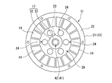
図1~3に示すように、ステータベース部13は、軸方向から見て平面視円形の板状に形成されたベース板部21を備える。複数のコイル14は、ベース板部21の一方の主面22上に設けられ、ベース板部21の周方向に配列される。これにより、複数のコイル14は、全体で円筒状に形成される。
平面視したベース板部21のうち複数のコイル14よりも内周側の部位には、ベース板部21の厚さ方向に貫通する複数の貫通孔23,24が形成されている。第一貫通孔23は、ベース板部21の軸線を中心とする平面視円形に形成されている。第二貫通孔24は、平面視で第一貫通孔23の周囲に複数形成されている。複数の貫通孔23,24の平面視形状は、任意であってよいが、本実施形態では円形状である。
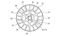
図1,2,4に示すように、ロータベース部15は、平面視円形の板状に形成されている。複数の永久磁石16は、前述したベース板部21の一方の主面22に対向するロータベース部15の一方の主面25に固定される。複数の永久磁石16は、ロータベース部15の周方向に配列される。ステータ11のベース板部21側に向く複数の永久磁石16の磁極は、ロータベース部15の周方向に交互に現れる。
その上で、ステータ11及びロータ12は、複数のコイル14と複数の永久磁石16とが回転軸102の軸方向に対向するように間隔をあけて配列される。
その上で、ステータ11及びロータ12は、複数のコイル14と複数の永久磁石16とが回転軸102の軸方向に対向するように間隔をあけて配列される。
平面視したロータベース部15のうち複数の永久磁石16よりも内周側の部位には、ロータベース部15の厚さ方向に貫通する複数の貫通孔26,27が形成されている。第三貫通孔26は、ロータベース部15の軸線を中心とする平面視円形に形成されている。
第四貫通孔27は、平面視で第三貫通孔26の周囲に複数形成されている。第四貫通孔27の平面視形状は、任意であってよいが、本実施形態では円弧状である。
第四貫通孔27は、平面視で第三貫通孔26の周囲に複数形成されている。第四貫通孔27の平面視形状は、任意であってよいが、本実施形態では円弧状である。
図1~4に示すように、本実施形態の回転電機2は、ステータ11とロータ12とを互いに回転可能に連結する連結軸部17をさらに備える。連結軸部17は、回転軸102の軸方向においてステータ11とロータ12との相対的な位置を固定する。連結軸部17は、軸部本体31と、軸受部32と、を備える。
軸部本体31は、回転軸102の軸方向に延びて形成され、ステータベース部13の第一貫通孔23及びロータベース部15の第三貫通孔26に挿通される。軸部本体31は、例えばステータベース部13に固定されてもよいが、本実施形態では、ロータベース部15に固定される。
軸部本体31のうち軸方向の第一端部には、軸部本体31をロータベース部15に固定するためのフランジ部33が形成されている。フランジ部33には、軸部本体31を挿通したロータベース部15のうち第三貫通孔26と複数の第四貫通孔27との間の部位が当接する。ロータベース部15とフランジ部33とを固定する方法は、ネジ止めなど任意であってよい。ロータベース部15とフランジ部33とを固定した状態では、ロータ12及び連結軸部17の軸線が一致する。
軸受部32は、連結軸部17によって連結されたステータ11及びロータ12を相互に回転可能とする。軸受部32は、例えば玉軸受やころ軸受などのラジアル軸受である。軸受部32は、例えば軸部本体31の外周とロータベース部15の第三貫通孔26との間に設けられてもよいが、本実施形態では、軸部本体31の外周とステータベース部13の第一貫通孔23との間に設けられる。
軸受部32は、ステータベース部13の第一貫通孔23内に固定される。また、軸受部32は、軸部本体31の軸方向の第二端部に位置決めされる。具体的に説明すれば、軸部本体31の第二端部には、軸部本体31の軸方向に向く係止面34が形成されている。軸部本体31の係止面34に軸受部32の内周部が当接することで、軸受部32及びこれに固定されたステータベース部13が軸部本体31の第二端部に位置決めされる。
すなわち、連結軸部17は、そのフランジ部33及び係止面34によって、軸方向におけるステータベース部13とロータベース部15との間隔、より具体的には、ステータ11のコイル14とロータ12の永久磁石16との隙間(ギャップ)を設定する。
すなわち、連結軸部17は、そのフランジ部33及び係止面34によって、軸方向におけるステータベース部13とロータベース部15との間隔、より具体的には、ステータ11のコイル14とロータ12の永久磁石16との隙間(ギャップ)を設定する。
ロータ12は、例えば直接エンジン100の回転軸102に固定されてもよいが、本実施形態では、連結軸部17を介して回転軸102に固定される。本実施形態の連結軸部17には、これをエンジン100の回転軸102に固定するための固定部35が設けられている。
固定部35は、例えば軸部本体31の第二端部(ステータ11側)に設けられてもよいが、本実施形態では、軸部本体31の第一端部(ロータ12側)に設けられる。このため、ロータ12を回転軸102に固定した状態では、ロータ12とステータ11とが、エンジン100側からこの順で配列される。また、本実施形態において、固定部35は、軸部本体31の軸方向においてロータベース部15から回転電機2の外側に突出している。
固定部35は、軸部本体31の第一端部において軸部本体31の軸方向に向く第一端面36から窪む有底の挿入孔37と、挿入孔37に挿入された回転軸102の端部を軸部本体31に固定するためのネジ38と、を備える。
挿入孔37は、回転軸102の端部が嵌るように形成されている。ネジ38は、少なくとも挿入孔37の内面から挿入孔37内に突出するように軸部本体31に取り付けられると共に、挿入孔37に挿入された回転軸102の端部に螺着されればよい。本実施形態において、ネジ38は、挿入孔37の底面から軸部本体31の軸方向に突出するように軸部本体31に取り付けられる。これにより、回転軸102の端部を軸部本体31に固定できる。
連結軸部17と回転軸102とを互いに固定した状態では、連結軸部17の軸線が回転軸102の軸線L1に一致する。これにより、回転電機2の軸線が回転軸102の軸線L1に一致する。
挿入孔37は、回転軸102の端部が嵌るように形成されている。ネジ38は、少なくとも挿入孔37の内面から挿入孔37内に突出するように軸部本体31に取り付けられると共に、挿入孔37に挿入された回転軸102の端部に螺着されればよい。本実施形態において、ネジ38は、挿入孔37の底面から軸部本体31の軸方向に突出するように軸部本体31に取り付けられる。これにより、回転軸102の端部を軸部本体31に固定できる。
連結軸部17と回転軸102とを互いに固定した状態では、連結軸部17の軸線が回転軸102の軸線L1に一致する。これにより、回転電機2の軸線が回転軸102の軸線L1に一致する。
上記した回転電機2は、その内周部に、後述する遠心ファン4の回転に伴って、回転軸102の軸方向において回転電機2の一方側から他方側に空気を流す通風流路部40を有する。回転電機2の一方側及び他方側は、それぞれ回転電機2の一方側の空間、及び、他方側の空間を意味する。
本実施形態において、通風流路部40は、ステータベース部13の複数の第二貫通孔24と、周方向に配列された複数のコイル14の内周側の空間(以下、内周側空間29と呼ぶ。)と、ロータベース部15の複数の第四貫通孔27と、を備える。
本実施形態において、通風流路部40は、ステータベース部13の複数の第二貫通孔24と、周方向に配列された複数のコイル14の内周側の空間(以下、内周側空間29と呼ぶ。)と、ロータベース部15の複数の第四貫通孔27と、を備える。
複数のコイル14の内周側空間29は、回転軸102の軸方向においてステータベース部13とロータベース部15との間に位置する。内周側空間29は、複数の第二貫通孔24によって回転電機2の一方側に連通する。また、内周側空間29は、複数の第四貫通孔27によって回転電機2の他方側に連通する。
言い換えれば、ステータベース部13及び複数のコイル14は、軸方向からみて複数の第二貫通孔24と内周側空間29とが重なるように配される。また、ステータ11(特に複数のコイル14)及びロータ12(特にロータベース部15)は、軸方向から見て内周側空間29と複数の第四貫通孔27とが重なるように配される。
これにより、空気は、回転電機2の一方側から、複数の第二貫通孔24、内周側空間29及び複数の第四貫通孔27を通して、回転電機2の他方側に流れることができる。
言い換えれば、ステータベース部13及び複数のコイル14は、軸方向からみて複数の第二貫通孔24と内周側空間29とが重なるように配される。また、ステータ11(特に複数のコイル14)及びロータ12(特にロータベース部15)は、軸方向から見て内周側空間29と複数の第四貫通孔27とが重なるように配される。
これにより、空気は、回転電機2の一方側から、複数の第二貫通孔24、内周側空間29及び複数の第四貫通孔27を通して、回転電機2の他方側に流れることができる。
本実施形態において、通風流路部40は、連結軸部17に形成される軸部内流路41をさらに備える。軸部内流路41は、空気を、回転軸102の軸方向において回転電機2の一端に位置する連結軸部17の端面(後述する第二端面39)から連結軸部17の内部に流入させ、軸方向において回転電機2の一端よりも回転電機2の他端側にずれた位置で連結軸部17の外周面から外側に流出させる。以下、本実施形態の軸部内流路41について具体的に説明する。
軸部内流路41は、軸部本体31の軸方向に延びる軸方向孔部42と、軸部本体31の径方向に延びる径方向孔部43と、を備える。
軸方向孔部42は、回転電機2の一端に対応する軸部本体31の第二端部において軸部本体31の軸方向に向く軸部本体31の第二端面39に開口する有底の孔である。
軸方向孔部42は、回転電機2の一端に対応する軸部本体31の第二端部において軸部本体31の軸方向に向く軸部本体31の第二端面39に開口する有底の孔である。
径方向孔部43は、軸方向孔部42の底部において、軸方向孔部42を構成する軸部本体31の内周面から軸部本体31の外周面まで貫通する。径方向孔部43は、ロータベース部15とステータベース部13のベース板部21との間において軸部本体31の外周側に開口する。本実施形態において、径方向孔部43は、軸方向孔部42と複数のコイル14の内周側空間29とを連通する。径方向孔部43は、例えば軸部本体31の周方向に複数配列されてもよいが、本実施形態では一つだけ形成されている。
図1,2に示すように、コントロールユニット3は、不図示の配線によって回転電機2に電気接続され、回転電機2の動作を制御するように構成される。コントロールユニット3は、例えば回転電機2をスタータモータとして機能させる際に、回転電機2に供給する電力を制御する。また、コントロールユニット3は、例えば回転電機2が発電機として機能する際に、回転電機2において発電された電力の電圧や電流を適宜調整した上で、発電電力をバッテリ(不図示)に充電したり、各種電気部品(不図示)に直接供給したりする。
コントロールユニット3の外観形状は、任意であってよいが、本実施形態では厚さの大きい円板状に形成されている。
コントロールユニット3は、回転電機2の動作を制御するための制御回路部51と、制御回路部51を収容するケース52と、を備える。また、コントロールユニット3は、制御回路部51をケース52内において封止する封止樹脂53をさらに備える。また、コントロールユニット3は、制御回路部51を、回転電機2、バッテリ、各種電気部品と電気接続するためのコネクタなどの端子(不図示)をさらに備える。
コントロールユニット3は、回転電機2の動作を制御するための制御回路部51と、制御回路部51を収容するケース52と、を備える。また、コントロールユニット3は、制御回路部51をケース52内において封止する封止樹脂53をさらに備える。また、コントロールユニット3は、制御回路部51を、回転電機2、バッテリ、各種電気部品と電気接続するためのコネクタなどの端子(不図示)をさらに備える。
本実施形態の制御回路部51は、基板54と、基板54に搭載される電子部品55と、を備える。図1,2において、基板54には電子部品55が一つだけ搭載されているが、例えば様々な大きさや種類の電子部品55が複数搭載されてもよい。図1,2に記載の電子部品55は、回転電機2の動作を制御する際に主に発熱するコントロールユニット3の発熱源である。
ケース52は、コントロールユニット3の外観をなす。ケース52は、コントロールユニット3の厚さ方向の一方に開口する。本実施形態のケース52は、板状の底壁部56と、底壁部56の周縁において底壁部56の板厚方向に延びる筒状の周壁部57と、を備える。発熱源としての電子部品55は、ケース52の開口近傍に配される。
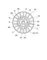
図1,2,5に示すように、遠心ファン4は、前述したロータ12と同様に、エンジン100の回転軸102と共に回転するように設けられる。遠心ファン4は、複数の羽根61を周方向に配列した羽根部62を有する。遠心ファン4は、その軸線を中心に回転することで空気を径方向において羽根部62の内側から外側に流すように構成される。本実施形態の遠心ファン4は、シロッコファンであり、円筒状の外観を有する。
図1,2に示すように、上記したコントロールユニット3、回転電機2及び遠心ファン4は、回転軸102の軸方向に順番に配列される。
コントロールユニット3は、回転軸102の軸方向における回転電機2の一方側に配される。すなわち、コントロールユニット3は、回転軸102の軸方向において回転電機2のステータベース部13に対向するように配される。コントロールユニット3は、回転軸102の軸方向から見た平面視で回転電機2の通風流路部40と重なるように配される。本実施形態において、コントロールユニット3は、回転電機2に対して回転軸102の軸方向に間隔をあけて配される。
コントロールユニット3は、回転軸102の軸方向における回転電機2の一方側に配される。すなわち、コントロールユニット3は、回転軸102の軸方向において回転電機2のステータベース部13に対向するように配される。コントロールユニット3は、回転軸102の軸方向から見た平面視で回転電機2の通風流路部40と重なるように配される。本実施形態において、コントロールユニット3は、回転電機2に対して回転軸102の軸方向に間隔をあけて配される。
また、本実施形態において、コントロールユニット3は、そのケース52の開口がステータベース部13に対向するように配される。このため、発熱源としての電子部品55が、コントロールユニット3のうち回転電機2に対向する部位に配される。
一方、遠心ファン4は、回転軸102の軸方向における回転電機2の他方側に配される。すなわち、遠心ファン4は、回転軸102の軸方向において回転電機2のロータベース部15に対向するように配される。遠心ファン4は、回転軸102の軸方向から見た平面視で、回転電機2の通風流路部40が円筒状とされた羽根部62の径方向において羽根部62よりも内側に位置するように配される。
遠心ファン4は、例えば無端ベルトやギヤ(いずれも不図示)を介して回転軸102に連結されたり、回転軸102に直接固定されたりしてもよいが、本実施形態では、ロータ12を介してエンジン100の回転軸102に固定される。すなわち、遠心ファン4はロータ12に固定される。
ロータ12に対する遠心ファン4の固定についてより具体的に説明する。
図1,2,5に示すように、本実施形態の遠心ファン4は、円筒状とされた羽根部62の軸方向の第一端部に配され、径方向において羽根部62よりも内側に延出する円環状板部63を有する。円環状板部63は、複数の第四貫通孔27を塞がないようにロータベース部15に対してその板厚方向に重ねて配される。その上で、円環状板部63は、ネジ止め等によってロータベース部15に固定される。これにより、遠心ファン4がロータ12に固定される。
遠心ファン4をロータ12に固定した状態において、遠心ファン4及びロータ12の軸線は、互いに一致する。また、この状態では、連結軸部17の固定部35が遠心ファン4の内側に配される。このため、本実施形態では、エンジン100が遠心ファン4に対して羽根部62の第二端部側に配される。
図1,2,5に示すように、本実施形態の遠心ファン4は、円筒状とされた羽根部62の軸方向の第一端部に配され、径方向において羽根部62よりも内側に延出する円環状板部63を有する。円環状板部63は、複数の第四貫通孔27を塞がないようにロータベース部15に対してその板厚方向に重ねて配される。その上で、円環状板部63は、ネジ止め等によってロータベース部15に固定される。これにより、遠心ファン4がロータ12に固定される。
遠心ファン4をロータ12に固定した状態において、遠心ファン4及びロータ12の軸線は、互いに一致する。また、この状態では、連結軸部17の固定部35が遠心ファン4の内側に配される。このため、本実施形態では、エンジン100が遠心ファン4に対して羽根部62の第二端部側に配される。
図1,2に示すように、本実施形態の回転電機ユニット1は、回転電機2のステータ11をエンジン100の本体部101に取り付ける取付部70をさらに備える。取付部70は、例えばステータ11を本体部101に対して移動不能に取り付けてもよいが、本実施形態ではステータ11を本体部101に対して回転軸102の軸方向のみに移動可能に取り付ける。その上で、回転電機ユニット1は、回転軸102の軸方向においてステータ11の両側に配され、ステータを取付部70に対して軸方向に付勢する一対の付勢部71,71をさらに備える。
具体的に説明すれば、本実施形態の取付部70は、平面視環状に形成されてステータ11を支持する支持部72と、支持部72から回転軸102の軸方向に延びてエンジン100の本体部101まで到達する延出部73と、を備える。
支持部72は、ステータ11に対して軸方向の両側に間隔をあけて配され、ステータ11の軸方向への移動範囲を所定の範囲に制限する一対の制限壁部74,74と、径方向においてステータ11の外側に配されて、一対の制限壁部74,74を連結する連結壁部75と、を有する。
支持部72は、ステータ11に対して軸方向の両側に間隔をあけて配され、ステータ11の軸方向への移動範囲を所定の範囲に制限する一対の制限壁部74,74と、径方向においてステータ11の外側に配されて、一対の制限壁部74,74を連結する連結壁部75と、を有する。
一対の制限壁部74,74の間には、ステータ11のベース板部21のうち径方向において複数のコイル14よりも外側に位置する外周縁部が配される。一対の制限壁部74,74は、例えばステータ11の周方向に間隔をあけて複数設けられてもよいが、本実施形態では平面視環状に形成される。このため、ベース板部21の外周縁部の周方向全体が、一対の制限壁部74,74の間に配される。
ステータ11が一対の制限壁部74,74の間において軸方向のみに移動可能とするためには、例えば、一対の制限壁部74,74の間で軸方向に延びるピン(不図示)を設け、ピンをベース板部21の外周縁部に挿通させればよい。
ステータ11が一対の制限壁部74,74の間において軸方向のみに移動可能とするためには、例えば、一対の制限壁部74,74の間で軸方向に延びるピン(不図示)を設け、ピンをベース板部21の外周縁部に挿通させればよい。
延出部73は、上記した支持部72と一体に形成されている。延出部73は、径方向において回転電機2や遠心ファン4の外側に配される。
延出部73は、例えば周方向に間隔をあけて配列された複数の棒状部材によって構成されてもよいが、本実施形態では、径方向において回転電機2や遠心ファン4の外側を囲む円筒状に形成されている。すなわち、本実施形態の取付部70は、回転電機2や遠心ファン4を収容する円筒状のケース52として機能する。
延出部73は、例えば周方向に間隔をあけて配列された複数の棒状部材によって構成されてもよいが、本実施形態では、径方向において回転電機2や遠心ファン4の外側を囲む円筒状に形成されている。すなわち、本実施形態の取付部70は、回転電機2や遠心ファン4を収容する円筒状のケース52として機能する。
本実施形態の延出部73には、遠心ファン4の回転に伴って羽根部62の外側に流れ出た空気を所定の方向に流すための通風用貫通孔76が形成されている。
通風用貫通孔76は、延出部73のうち羽根部62の外側に対向する部位において、延出部73をその径方向に貫通して形成されている。通風用貫通孔76は、延出部73の周方向の一部に形成されている。図示例において、通風用貫通孔76は一つだけ形成されているが、例えば複数形成されてもよい。
通風用貫通孔76は、延出部73のうち羽根部62の外側に対向する部位において、延出部73をその径方向に貫通して形成されている。通風用貫通孔76は、延出部73の周方向の一部に形成されている。図示例において、通風用貫通孔76は一つだけ形成されているが、例えば複数形成されてもよい。
延出部73の延出方向の先端部は、エンジン100の本体部101のうち回転軸102が突出する面(取付面104)に対してネジ止め等によって固定される。これにより、ステータ11は、取付部70を介してエンジン100の本体部101に取り付けられる。ステータ11を本体部101に取り付けた状態では、ステータ11がロータ12と共に回転してしまうことを防止できる。
一対の付勢部71,71は、それぞれベース板部21の外周縁部と制限壁部74との間に配される。一対の付勢部71,71は、例えば、ベース板部21の周方向に間隔をあけて複数組配される。ステータ11は、一対の付勢部71,71の付勢力によって一対の制限壁部74,74の間において安定した状態で配される。付勢部71は、図示例のようなコイルばねであってもよいし、例えば板ばねやゴム等であってもよい。
コントロールユニット3は、例えば回転電機2のステータ11に固定されてもよいが、本実施形態では取付部70に固定される。本実施形態において、コントロールユニット3は、スペーサ77を介して平面視環状に形成された支持部72に固定される。本実施形態において、スペーサ77は、支持部72の周方向に間隔をあけて複数配される。これにより、回転電機2の通風流路部40は、回転電機2や支持部72とコントロールユニット3との隙間を介して外部空間に連通する。この構成において、遠心ファン4が回転する際には、外部空間の空気が回転電機2とコントロールユニット3との隙間から通風流路部40に向けて流れる。
さらに、本実施形態では、回転電機ユニット1をエンジン100に取り付けた構成の一部あるいは全体が、エンジンカバー103によって覆われている。エンジンカバー103は、遠心ファン4の回転に伴って羽根部62の外側に流れた空気の一部が、図1において矢印F8で示すように、エンジン100の所定部位(例えばエンジン100の燃焼室の近傍)に向けて流れるように形成されている。
本実施形態の回転電機ユニット1は、前述した取付部70の通風用貫通孔76がエンジンカバー103に対向するようにエンジン100に取り付けられる。
本実施形態の回転電機ユニット1は、前述した取付部70の通風用貫通孔76がエンジンカバー103に対向するようにエンジン100に取り付けられる。
本実施形態の回転電機ユニット1において、遠心ファン4がエンジン100あるいは回転電機2から駆動力を得て回転する際には、空気がコントロールユニット3の近傍と、回転電機2の内周部にある通風流路部40と、を順番に流れた上で、羽根部62の内側から外側に流れる。
具体的に説明すれば、遠心ファン4が回転した際には、図1において矢印F1で示すように、空気が、径方向に流れて外部空間から回転電機2とコントロールユニット3との隙間に入り込む。これにより、空気が、コントロールユニット3のうち回転電機2に対向する部位(対向部位)に沿って流れる。すなわち、空気が、コントロールユニット3の対向部位の近傍に流れる。
回転電機2とコントロールユニット3との隙間に入り込んだ空気は、図1において矢印F2,F3で示すように、回転電機2の一方側から回転電機2の通風流路部40に流れ込み、軸方向に流れる。
本実施形態において、回転電機2とコントロールユニット3との隙間に入り込んだ空気の一部は、図1において矢印F2で示すように、ステータベース部13の複数の第二貫通孔24から複数のコイル14の内周側空間29に入り込み、ロータベース部15に向けて軸方向に流れる。
本実施形態において、回転電機2とコントロールユニット3との隙間に入り込んだ空気の一部は、図1において矢印F2で示すように、ステータベース部13の複数の第二貫通孔24から複数のコイル14の内周側空間29に入り込み、ロータベース部15に向けて軸方向に流れる。
回転電機2とコントロールユニット3との隙間に入り込んだ空気の残部は、図1において矢印F3で示すように、連結軸部17の軸部内流路41に入り込み、ステータベース部13側からロータベース部15側に向けて軸方向に流れる。軸部内流路41を流れる空気は、図1において矢印F4で示すように、軸部内流路41の径方向孔部43を通ることで軸部内流路41の内側から外側に流れ、複数のコイル14の内周側空間29に入り込む。矢印F4で示す空気の流れは、コイル14の内周側空間29において矢印F2で示す空気の流れと合流する。
内周側空間29において合流した空気の流れは、図1において矢印F5で示すように、軸方向に流れ、ロータベース部15の第四貫通孔27を通って回転電機2の他方側に流れ出ると共に遠心ファン4(羽根部62)の内側に入り込む。
遠心ファン4(羽根部62)の内側に入り込んだ空気は、図1において矢印F6で示すように、羽根部62の内側から外側に流れる。
遠心ファン4(羽根部62)の内側に入り込んだ空気は、図1において矢印F6で示すように、羽根部62の内側から外側に流れる。
羽根部62の外側に流れ出た空気は、図1において矢印F7で示すように、羽根部62の外側を囲む円筒状の延出部73に形成された通風用貫通孔76を通して、延出部73の外側に流れ出る。
延出部73の外側に流れ出た空気は、図1において矢印F8で示すように、エンジンカバー103によってエンジン100の所定部位に向けて流れる。
延出部73の外側に流れ出た空気は、図1において矢印F8で示すように、エンジンカバー103によってエンジン100の所定部位に向けて流れる。
以上説明したように、本実施形態の回転電機ユニット1によれば、遠心ファン4の回転に伴って空気がコントロールユニット3の近傍に流れるため、コントロールユニット3が積極的に冷却される。このため、コントロールユニット3が受けるエンジン100の熱の影響を抑制することが可能となり、コントロールユニット3を回転電機2と共にエンジン100の近くに配置することができる。したがって、回転電機2とコントロールユニット3とを接続する配線を短くして、回転電機2とコントロールユニット3との間における電圧損失を抑制することができる。これにより、回転電機2における発電量を増加したり、小さい消費電力で効率よくエンジン100を始動したりすることができる。
また、遠心ファン4の回転駆動力は、エンジン100あるいは回転電機2から得られるため、遠心ファン4を駆動する駆動源を別途用意する必要がなく、コントロールユニット3を効率よく冷却することができる。
また、遠心ファン4の回転駆動力は、エンジン100あるいは回転電機2から得られるため、遠心ファン4を駆動する駆動源を別途用意する必要がなく、コントロールユニット3を効率よく冷却することができる。
また、本実施形態では、コントロールユニット3とエンジン100との間に遠心ファン4が配されることで、コントロールユニット3の近傍で流れた空気が、コントロールユニット3からエンジン100側に向けて流れる。このため、コントロールユニット3が受けるエンジン100の熱の影響を効果的に抑制することができる。
また、本実施形態の回転電機ユニット1によれば、回転電機2がアキシャルギャップ型回転電機であるため、ラジアルギャップ型回転電機と比較して軸方向における回転電機2の寸法(厚さ寸法)を小さく設定できる。したがって、回転電機ユニット1の薄型化を図ることができる。
また、本実施形態の回転電機ユニット1によれば、アキシャルギャップ型回転電機をなすステータ11とロータ12とが連結軸部17によって連結されている。このため、回転電機2をエンジン100に組み付ける前に、予め、軸方向におけるステータ11とロータ12との隙間(ギャップ)を連結軸部17によって設定することができる。これにより、ステータ11とロータ12との隙間を容易に狭く設定することが可能となり、回転電機2の性能向上を容易に図ることができる。
また、本実施形態の回転電機ユニット1によれば、回転電機2の通風流路部40が連結軸部17に形成される軸部内流路41を備える。このため、回転電機2がステータ11とロータ12とを連結軸部17で連結して構成されても、軸方向に直交する通風流路部40の流路断面を大きく設定できる。したがって、より多くの空気をコントロールユニット3側から遠心ファン4側に流すことができ、コントロールユニット3を効率よく冷却することができる。
また、本実施形態の回転電機ユニット1では、回転電機2のロータ12が連結軸部17を介してエンジン100の回転軸102の端部に取り付けられる。その上で、回転電機2のステータ11が、取付部70によってエンジン100の本体部101に対して軸方向のみに移動可能に取り付けられる。このため、エンジン100の本体部101から突出する回転軸102の突出長さにばらつきがあっても、回転電機2を取り付ける際に回転電機2が本体部101に対して回転軸102の軸方向に移動することで、回転電機2を安定してエンジン100に取り付けることができる。
また、本実施形態の回転電機ユニット1によれば、一対の付勢部71,71が軸方向においてステータ11の両側に配され、ステータ11を取付部70に対して軸方向に付勢する。このため、取付部70やエンジン100の本体部101に対するステータ11(回転電機2)の軸方向の位置を、一対の付勢部71,71の付勢力によって安定させることができる。
また、本実施形態の回転電機ユニット1によれば、回転電機2とコントロールユニット3とが軸方向に間隔をあけて配される。このため、コントロールユニット3のうち回転電機2に対向する対向部位を、特に効率よく冷却することができる。本実施形態では、コントロールユニット3の対向部位に発熱源としての電子部品55が配されているため、この電子部品55を効率よく冷却することができる。
また、本実施形態の回転電機ユニット1によれば、遠心ファン4及びロータ12が同軸上に配される。このため、遠心ファン4及びロータ12の両方を、無端ベルトやギヤを介さずにエンジン100の回転軸102に直接接続できる。すなわち、回転電機ユニット1の構成部品点数を少なく設定できる。
さらに、本実施形態の回転電機ユニット1によれば、径方向において羽根部62の外側を囲む取付部70の周方向の一部にのみ通風用貫通孔76が形成される。このため、回転する遠心ファン4の外側に流れ出た空気を、図1において矢印F7で示すように、所望の方向に流すことが可能となる。これにより、通風用貫通孔76から取付部70の外部に流れ出た全ての空気を、図1において矢印F8で示すように、エンジン100の所定部位に流すことが可能となり、エンジン100の所定部位を効率よく冷却することができる。
〔第二実施形態〕
次に、本発明の第二実施形態について、図6~8を参照して第一実施形態との相違点を中心に説明する。なお、第一実施形態と共通する構成については、同一符号を付し、その説明を省略する。
次に、本発明の第二実施形態について、図6~8を参照して第一実施形態との相違点を中心に説明する。なお、第一実施形態と共通する構成については、同一符号を付し、その説明を省略する。
図6~8に示すように、本実施形態に係る回転電機ユニット1Aは、第一実施形態と同様に、回転電機2A、コントロールユニット3及び遠心ファン4を備える。コントロールユニット3及び遠心ファン4の構成は、第一実施形態と同様である。
本実施形態の回転電機2Aは、第一実施形態と同様のアキシャルギャップ型回転電機であり、ステータ11及びロータ12Aを備える。本実施形態のロータ12Aは、第一実施形態と同様に、平面視円形の板状に形成されたロータベース部15Aと、ロータベース部15Aの一方の主面25に固定される複数の永久磁石16と、を備える。
本実施形態の回転電機2Aは、第一実施形態と同様のアキシャルギャップ型回転電機であり、ステータ11及びロータ12Aを備える。本実施形態のロータ12Aは、第一実施形態と同様に、平面視円形の板状に形成されたロータベース部15Aと、ロータベース部15Aの一方の主面25に固定される複数の永久磁石16と、を備える。
ただし、本実施形態のロータベース部15Aのうち複数の永久磁石16よりも内周側の部位には、ロータベース部15Aの厚さ方向に貫通する第五貫通孔27Aが一つだけ形成されている。ロータベース部15Aの第五貫通孔27Aは、ロータベース部15Aの軸線を中心とする平面視円形に形成されている。平面視した第五貫通孔27Aの大きさは、第一実施形態のロータベース部15Aに形成された第三、第四貫通孔26,27(図4参照)よりも大きい。ロータベース部15Aの第五貫通孔27Aは、例えば第一実施形態のロータベース部15Aのうち第三、第四貫通孔26,27の形成領域全体を含む大きさに形成されている。
ロータベース部15Aの第五貫通孔27Aは、ステータベース部13の複数の第二貫通孔24、及び、複数のコイル14の内周側空間29と共に、遠心ファン4の回転に伴って回転電機2Aの一方側から他方側に空気を流す通風流路部40Aを構成する。ただし、本実施形態では、ロータベース部15Aの第五貫通孔27Aに後述する連結軸部17Aの軸部本体31Aが挿通されるため、ロータベース部15Aの第五貫通孔27Aのうち軸部本体31Aの挿通部分を除く部分が、通風流路部40Aとして機能する。
本実施形態の回転電機ユニット1Aでは、遠心ファン4及びロータ12Aが補強フレーム80Aを介して一体に固定されている。補強フレーム80Aは、例えば第一実施形態のロータベース部15Aと同様の形状に形成されてもよいが、本実施形態では異なる形状に形成されている。
本実施形態の補強フレーム80Aは、平面視円環の板状に形成された環状部81Aと、環状部81Aの内縁から環状部81Aの厚さ方向の一方に延出する円筒部82Aと、円筒部82Aの軸方向の一端を閉塞する板状の蓋部83Aと、を備える。
本実施形態の補強フレーム80Aは、平面視円環の板状に形成された環状部81Aと、環状部81Aの内縁から環状部81Aの厚さ方向の一方に延出する円筒部82Aと、円筒部82Aの軸方向の一端を閉塞する板状の蓋部83Aと、を備える。
円筒部82Aには、その厚さ方向に貫通する流通孔84Aが形成されている。これにより、空気を径方向において円筒部82Aの内側から外側に流すことができる。流通孔84Aは、例えば円筒部82Aの周方向の一部に一つだけ形成されてもよいが、本実施形態では、円筒部82Aの周方向に間隔をあけて複数形成されている。図示例において、円筒部82Aは、環状部81Aの厚さ方向に向かうにしたがって、径方向において環状部81Aからその内側に離れるように傾斜しているが、例えば環状部81Aの厚さ方向に平行して延びてもよい。
蓋部83Aには、その板厚方向に貫通する挿通孔85Aが形成されている。挿通孔85Aには、後述する連結軸部17Aの軸部本体31Aが挿通される。
蓋部83Aには、その板厚方向に貫通する挿通孔85Aが形成されている。挿通孔85Aには、後述する連結軸部17Aの軸部本体31Aが挿通される。
環状部81Aは、軸方向において遠心ファン4の円環状板部63とロータベース部15Aとの間に配される。ロータ12A、補強フレーム80A及び遠心ファン4は、ロータベース部15A、環状部81A及び円環状板部63を板厚方向に順番に重ねた上で、ネジ止め等によって相互に固定することで、一体に固定される。ロータ12A、補強フレーム80A及び遠心ファン4を固定した状態では、ロータ12A、補強フレーム80A及び遠心ファン4の軸線が一致する。
円筒部82A及び蓋部83Aは、遠心ファン4の羽根部62の第一端部から羽根部62の内側に挿入される。軸方向における円筒部82Aの長さは、例えば遠心ファン4の軸方向長さよりも長くてもよいが、本実施形態では遠心ファン4の軸方向長さよりも短い。このため、円筒部82A及び蓋部83Aは、羽根部62の内側に配される。
本実施形態の回転電機2Aは、第一実施形態と同様の連結軸部17Aを備える。本実施形態の連結軸部17Aは、第一実施形態と同様の軸部本体31A及び軸受部32を備える。
ただし、本実施形態において、軸部本体31Aのうち軸方向の第一端部に形成されるフランジ部33Aは、軸部本体31Aを補強フレーム80Aに固定するためのものである。フランジ部33Aには、軸部本体31Aを挿通した補強フレーム80Aの蓋部83Aに当接する。補強フレーム80Aとフランジ部33Aとを固定する方法は、ネジ止めなど任意であってよい。補強フレーム80Aとフランジ部33Aとを固定した状態では、補強フレーム80A及び連結軸部17Aの軸線が一致する。すなわち、ロータ12A、遠心ファン4及び連結軸部17Aの軸線が一致する。
ただし、本実施形態において、軸部本体31Aのうち軸方向の第一端部に形成されるフランジ部33Aは、軸部本体31Aを補強フレーム80Aに固定するためのものである。フランジ部33Aには、軸部本体31Aを挿通した補強フレーム80Aの蓋部83Aに当接する。補強フレーム80Aとフランジ部33Aとを固定する方法は、ネジ止めなど任意であってよい。補強フレーム80Aとフランジ部33Aとを固定した状態では、補強フレーム80A及び連結軸部17Aの軸線が一致する。すなわち、ロータ12A、遠心ファン4及び連結軸部17Aの軸線が一致する。
本実施形態において、通風流路部40Aを構成する連結軸部17Aの軸部内流路41は、第一実施形態と同様の軸方向孔部42及び径方向孔部43を備える。ただし、本実施形態において、径方向孔部43は、軸方向孔部42と補強フレーム80Aの円筒部82Aの内側空間86Aとを連通する。すなわち、径方向孔部43は、遠心ファン4の羽根部62の内側に位置する。また、径方向孔部43は、径方向において円筒部82Aの複数の流通孔84Aのうち少なくとも一つと対向するように配される。
本実施形態の回転電機ユニット1Aにおいても、遠心ファン4がエンジン100あるいは回転電機2Aから駆動力を得て回転する際には、空気がコントロールユニット3の近傍と、回転電機2Aの内周部にある通風流路部40Aと、を順番に流れた上で、羽根部62の内側から外側に流れる。
具体的に説明すれば、本実施形態の回転電機ユニット1Aにおいて、遠心ファン4が回転した際、図6において矢印F1,F2,F3,F6,F7,F8で示す空気の流れは、第一実施形態と同様である。
ただし、本実施形態において、軸部内流路41を流れる空気は、図6において矢印F4Aで示すように、軸部内流路41の径方向孔部43を通ることで軸部内流路41の内側から外側に流れ、遠心ファン4の内側に配された円筒部82Aの内側空間86Aに入り込む。
ただし、本実施形態において、軸部内流路41を流れる空気は、図6において矢印F4Aで示すように、軸部内流路41の径方向孔部43を通ることで軸部内流路41の内側から外側に流れ、遠心ファン4の内側に配された円筒部82Aの内側空間86Aに入り込む。
また、ステータベース部13の複数の第二貫通孔24からコイル14の内周側空間29に入り込んだ空気は、図6において矢印F5Aで示すように、ロータベース部15Aの第五貫通孔27Aを通って円筒部82Aの内側空間86Aに入り込み、蓋部83Aに到達することで、円筒部82Aに向けて径方向に流れる。
矢印F5Aで示す空気の流れには、軸部内流路41から円筒部82Aの内側空間86Aに流れる矢印F4Aで示す空気の流れが合流し、円筒部82Aの流通孔84Aを通って円筒部82Aの外側に流れ出る。円筒部82Aの外側に流れ出た空気は、その流れ方向を大きく変えずに、図6において矢印F6で示すように、羽根部62の内側から外側に流れる。
矢印F5Aで示す空気の流れには、軸部内流路41から円筒部82Aの内側空間86Aに流れる矢印F4Aで示す空気の流れが合流し、円筒部82Aの流通孔84Aを通って円筒部82Aの外側に流れ出る。円筒部82Aの外側に流れ出た空気は、その流れ方向を大きく変えずに、図6において矢印F6で示すように、羽根部62の内側から外側に流れる。
本実施形態の回転電機ユニット1Aによれば、第一実施形態と同様の効果を奏する。
また、本実施形態の回転電機ユニット1Aによれば、遠心ファン4及びロータ12Aが補強フレーム80Aを介して一体に固定されている。このため、遠心ファン4及びロータ12Aと回転軸102との間に補強フレーム80Aを介在させることができる。これにより、回転軸102の回転に伴って遠心ファン4やロータ12Aにかかる応力を軽減することができる。また、遠心ファン4の剛性向上を図ることもできる。
また、本実施形態の回転電機ユニット1Aによれば、遠心ファン4及びロータ12Aが補強フレーム80Aを介して一体に固定されている。このため、遠心ファン4及びロータ12Aと回転軸102との間に補強フレーム80Aを介在させることができる。これにより、回転軸102の回転に伴って遠心ファン4やロータ12Aにかかる応力を軽減することができる。また、遠心ファン4の剛性向上を図ることもできる。
また、本実施形態の回転電機ユニット1Aによれば、第一実施形態の回転電機ユニット1と比較して、空気の流れ方向が大きく変化する回数が少なくなり、空気抵抗を減少させることができる。すなわち、空気を効率よく回転電機2Aの一方側から他方側に流すことができる。
上記第二実施形態の回転電機ユニット1Aにおいては、連結軸部17Aの固定部35が、遠心ファン4から軸方向に突出して遠心ファン4の外側に配されているが、例えば第一実施形態と同様に遠心ファン4(羽根部62)の内側に配されてもよい。
〔第三実施形態〕
次に、本発明の第三実施形態について、図9を参照して第一、第二実施形態との相違点を中心に説明する。なお、第一、第二実施形態と共通する構成については、同一符号を付し、その説明を省略する。
次に、本発明の第三実施形態について、図9を参照して第一、第二実施形態との相違点を中心に説明する。なお、第一、第二実施形態と共通する構成については、同一符号を付し、その説明を省略する。
図9に示すように、本実施形態に係る回転電機ユニット1Bは、第一、第二実施形態と同様に、回転電機2A、コントロールユニット3B及び遠心ファン4を備える。遠心ファン4の構成は第一、第二実施形態と同様である。回転電機2Aの構成は第二実施形態と同様である。
コントロールユニット3Bは、第一実施形態と同様に回転電機2Aの動作を制御する。ただし、本実施形態のコントロールユニット3Bの外観形状は、第一、第二実施形態と異なり、円筒形状である。すなわち、本実施形態のコントロールユニット3Bは、軸方向に貫通するユニット流路部50Bを備える。
ユニット流路部50Bには、遠心ファン4の回転に伴って、回転軸102の軸方向においてコントロールユニット3Bの一方側から他方側に空気が流れる。ユニット流路部50Bは、回転電機2Aの通風流路部40Aと、回転軸102の軸方向に重なるように配される。
ユニット流路部50Bには、遠心ファン4の回転に伴って、回転軸102の軸方向においてコントロールユニット3Bの一方側から他方側に空気が流れる。ユニット流路部50Bは、回転電機2Aの通風流路部40Aと、回転軸102の軸方向に重なるように配される。
具体的に説明すれば、本実施形態のコントロールユニット3Bは、第一、第二実施形態と同様に、回転電機2Aの動作を制御するための制御回路部51Bと、これを収容するケース52Bと、制御回路部51Bをケース52B内において封止する封止樹脂53と、を備える。
制御回路部51Bは、第一、第二実施形態と同様の基板54B及び電子部品55Bを備える。基板54Bの形状は、第一、第二実施形態と異なり、例えば平面視円環状に形成される。
制御回路部51Bは、第一、第二実施形態と同様の基板54B及び電子部品55Bを備える。基板54Bの形状は、第一、第二実施形態と異なり、例えば平面視円環状に形成される。
ケース52Bは、第一実施形態と同様に、コントロールユニット3Bの厚さ方向の一方に開口する。ただし、本実施形態のケース52Bは、平面視環形の板状に形成された環状底壁部56Bと、環状底壁部56Bの外周縁において環状底壁部56Bの板厚方向に延びる外側周壁部57Bと、環状底壁部56Bの内周縁において環状底壁部56Bの板厚方向に延びる内側周壁部58Bと、を備える。内側周壁部58Bは、径方向において外側周壁部57Bの内側に配される。
ケース52Bにおける制御回路部51Bの収容空間は、内側周壁部58Bと外側周壁部57Bとの間の空間である。本実施形態において、コントロールユニット3Bのユニット流路部50Bは、径方向において内側周壁部58Bの内側の空間である。発熱源としての電子部品55Bは、内側周壁部58Bの近傍に配されている。
上記したコントロールユニット3Bは、ユニット流路部50Bの軸方向が、回転軸102の軸方向に平行するように、回転電機2Aの一方側に配される。これにより、ユニット流路部50Bが、通風流路部40Aと回転軸102の軸方向に重なる。
図9に示す回転電機ユニット1Bでは、軸方向から見て、通風流路部40Aのうち軸部内流路41のみがユニット流路部50Bよりも内側に位置し、通風流路部40Aの他の部分(例えばステータベース部13の第二貫通孔24)がユニット流路部50Bの外側に位置するが、これに限ることはない。
図9に示す回転電機ユニット1Bでは、軸方向から見て、通風流路部40Aのうち軸部内流路41のみがユニット流路部50Bよりも内側に位置し、通風流路部40Aの他の部分(例えばステータベース部13の第二貫通孔24)がユニット流路部50Bの外側に位置するが、これに限ることはない。
コントロールユニット3Bは、例えば回転電機2Aに対して隙間なく重ねて配されてもよいが、本実施形態では、回転電機2Aに対して回転軸102の軸方向に間隔をあけて配される。
本実施形態において、コントロールユニット3Bは、円筒状に形成された取付部70の一方の開口を塞ぐように、取付部70の支持部72に直接固定される。このため、回転電機2Aの通風流路部40Aは、コントロールユニット3Bのユニット流路部50Bのみを介して外部空間に連通する。この構成において、遠心ファン4が回転する際には、外部空間の空気がコントロールユニット3Bのユニット流路部50Bを通って通風流路部40Aに向けて流れる。
本実施形態において、コントロールユニット3Bは、円筒状に形成された取付部70の一方の開口を塞ぐように、取付部70の支持部72に直接固定される。このため、回転電機2Aの通風流路部40Aは、コントロールユニット3Bのユニット流路部50Bのみを介して外部空間に連通する。この構成において、遠心ファン4が回転する際には、外部空間の空気がコントロールユニット3Bのユニット流路部50Bを通って通風流路部40Aに向けて流れる。
本実施形態の回転電機ユニット1Bにおいても、遠心ファン4がエンジン100あるいは回転電機2Aから駆動力を得て回転する際には、空気がコントロールユニット3Bの近傍と、回転電機2Aの内周部にある通風流路部40Aと、を順番に流れた上で、羽根部62の内側から外側に流れる。
具体的に説明すれば、遠心ファン4が回転した際には、図9において矢印F1Bで示すように、空気が、外部空間(コントロールユニット3Bの一方側の空間)からコントロールユニット3Bのユニット流路部50Bに流れ込み、軸方向に流れる。これにより、空気が、コントロールユニット3Bの内周部(内側周壁部58B)に沿って流れる。すなわち、空気が、コントロールユニット3Bの内周部近傍に流れる。
ユニット流路部50Bに流れ込んだ空気は、コントロールユニット3Bの他方側に流れ出る。
ユニット流路部50Bに流れ込んだ空気は、コントロールユニット3Bの他方側に流れ出る。
コントロールユニット3Bの他方側に流れ出た空気は、図9において矢印F2B,F3Bで示すように、回転電機2Aの一方側から回転電機2Aの通風流路部40Aに流れ込み、軸方向に流れる。矢印F2Bで示す空気の流れは、ステータベース部13の複数の第二貫通孔24から複数のコイル14の内周側空間29に入り込む流れである。矢印F3Bで示す空気の流れは、連結軸部17Aの軸部内流路41に入り込む流れである。
回転電機2Aの通風流路部40Aに入り込んだ後の空気の流れは、第二実施形態と同様である。
回転電機2Aの通風流路部40Aに入り込んだ後の空気の流れは、第二実施形態と同様である。
本実施形態の回転電機ユニット1Bによれば、第一、第二実施形態と同様の効果を奏する。
さらに、本実施形態の回転電機ユニット1Bによれば、コントロールユニット3Bのユニット流路部50Bと、回転電機2Aの通風流路部40Aとが、回転軸102の軸方向に配列される。このため、空気の流れ方向を大きく変えることなく、空気をコントロールユニット3Bから回転電機2Aに向けてスムーズに流すことができる。これにより、コントロールユニット3Bの近傍を流れる空気の流速向上を図り、コントロールユニット3Bを効率よく冷却することができる。
さらに、本実施形態の回転電機ユニット1Bによれば、コントロールユニット3Bのユニット流路部50Bと、回転電機2Aの通風流路部40Aとが、回転軸102の軸方向に配列される。このため、空気の流れ方向を大きく変えることなく、空気をコントロールユニット3Bから回転電機2Aに向けてスムーズに流すことができる。これにより、コントロールユニット3Bの近傍を流れる空気の流速向上を図り、コントロールユニット3Bを効率よく冷却することができる。
また、本実施形態の回転電機ユニット1Bによれば、ユニット流路部50Bを画成するコントロールユニット3Bの内周部に発熱源としての電子部品55が配置される。これにより、この電子部品55を効率よく冷却することができる。
また、本実施形態の回転電機ユニット1Bによれば、コントロールユニット3Bがユニット流路部50Bを備える。このため、第一、第二実施形態の構成と比較して、回転電機2Aとコントロールユニット3Bとの間隔を小さくする又は無くすことができる。これにより、回転電機ユニット1Bの軸方向の寸法を小さくして、回転電機ユニット1Bの小型化や薄型化を図ることができる。
第三実施形態の回転電機ユニット1Bの構成は、第一実施形態の回転電機ユニット1にも適用可能である。例えば、第一実施形態の回転電機ユニット1が、第三実施形態と同様のコントロールユニット3Bを備えてもよい。これに加えて、第一実施形態の回転電機ユニット1では、コントロールユニット3Bが、例えば回転電機2に対して隙間なく重ねて配されてもよいし、例えば取付部70の支持部72に直接固定されてもよい。
上記第三実施形態の回転電機ユニット1Bにおいて、コントロールユニット3Bは、例えば第一、第二実施形態と同様に、スペーサ77を介して取付部70の支持部72に固定されてもよい。この場合、回転電機2Aの通風流路部40Aは、軸方向における回転電機2Aや支持部72とコントロールユニット3Bとの隙間、及び、コントロールユニット3Bのユニット流路部50Bの両方を介して外部空間に連通する。
以上、本発明の詳細について説明したが、本発明は上述した実施形態に限定されるものではなく、本発明の主旨を逸脱しない範囲において種々の変更を加えることができる。
上記した全ての実施形態において、遠心ファンは、例えばターボファンであってもよい。
また、上記した全ての実施形態では、遠心ファン(羽根部)の外側に流れ出た空気が、エンジンの本体部を冷却するが、例えばエンジンを水冷で冷却するためのラジエータを冷却してもよい。
また、回転電機は、例えば、スタータモータのみを構成してもよいし、発電機のみを構成してもよい。
1,1A,1B 回転電機ユニット
2,2A 回転電機
3,3B コントロールユニット
4 遠心ファン
11 ステータ
12,12A ロータ
17,17A 連結軸部
39 第二端面(端面)
40,40A 通風流路部
41 軸部内流路
50B ユニット流路部
55,55B 電子部品(発熱源)
61 羽根
62 羽根部
70 取付部
71 付勢部
80A 補強フレーム
100 エンジン
101 本体部
102 回転軸
L1 軸線
2,2A 回転電機
3,3B コントロールユニット
4 遠心ファン
11 ステータ
12,12A ロータ
17,17A 連結軸部
39 第二端面(端面)
40,40A 通風流路部
41 軸部内流路
50B ユニット流路部
55,55B 電子部品(発熱源)
61 羽根
62 羽根部
70 取付部
71 付勢部
80A 補強フレーム
100 エンジン
101 本体部
102 回転軸
L1 軸線
Claims (9)
- ステータ、及び、該ステータに対して回転自在に設けられてエンジンの回転軸と共に回転するロータを有し、スタータモータ及び発電機の少なくとも一方を構成する回転電機と、
前記回転電機の動作を制御するように構成されたコントロールユニットと、
複数の羽根を周方向に配列した羽根部を有し、前記回転軸と共に回転することで空気を前記羽根部の内側から外側に流すように構成された遠心ファンと、
を備え、
前記コントロールユニット、前記回転電機及び前記遠心ファンが、前記回転軸の軸方向に順番に配列され、
前記回転電機は、その内周部に、前記遠心ファンの回転に伴って、前記軸方向において前記回転電機の一方側から他方側に空気を流す通風流路部を有し、
前記コントロールユニットが、平面視で前記通風流路部と重なるように配される回転電機ユニット。 - 前記回転電機は、前記軸方向において前記ステータと前記ロータとが互いに対向するように配置されたアキシャルギャップ型回転電機である請求項1に記載の回転電機ユニット。
- 前記回転電機が、前記ステータと前記ロータとを互いに回転可能に連結すると共に、前記軸方向において前記ステータと前記ロータとの相対的な位置を固定する連結軸部を備える請求項2に記載の回転電機ユニット。
- 前記通風流路部が、前記連結軸部に形成され、空気を、前記軸方向において前記回転電機の一端に位置する前記連結軸部の端面から前記連結軸部の内部に流入させ、前記軸方向において前記回転電機の一端よりも前記回転電機の他端側にずれた位置で前記連結軸部の外周面から外側に流出させる軸部内流路を備える請求項3に記載の回転電機ユニット。
- 前記ステータを、前記エンジンの本体部に対して前記軸方向のみに移動可能に取り付ける取付部と、
前記軸方向において前記ステータの両側に配され、前記ステータを前記取付部に対して前記軸方向に付勢する一対の付勢部と、
を備える請求項4に記載の回転電機ユニット。 - 前記回転電機と前記コントロールユニットとが前記軸方向に間隔をあけて配され、
前記遠心ファンの回転に伴って、空気が、前記回転電機と前記コントロールユニットとの隙間から前記通風流路部に向けて流れる請求項1から請求項5のいずれか一項に記載の回転電機ユニット。 - 前記コントロールユニットが、前記軸方向において貫通し、前記遠心ファンの回転に伴って、前記軸方向において前記コントロールユニットの一方側から他方側に空気を流すユニット流路部を備え、
前記ユニット流路部が、前記通風流路部と前記軸方向に重なるように配される請求項1から請求項6のいずれか一項に記載の回転電機ユニット。 - 前記遠心ファン及び前記ロータの軸線が互いに一致している請求項1から請求項7のいずれか一項に記載の回転電機ユニット。
- 前記遠心ファン及び前記ロータが、補強フレームを介して一体に固定されている請求項8に記載の回転電機ユニット。
Priority Applications (2)
| Application Number | Priority Date | Filing Date | Title |
|---|---|---|---|
| JP2016526953A JP6172877B2 (ja) | 2015-07-31 | 2015-07-31 | 回転電機ユニット |
| PCT/JP2015/071772 WO2017022007A1 (ja) | 2015-07-31 | 2015-07-31 | 回転電機ユニット |
Applications Claiming Priority (1)
| Application Number | Priority Date | Filing Date | Title |
|---|---|---|---|
| PCT/JP2015/071772 WO2017022007A1 (ja) | 2015-07-31 | 2015-07-31 | 回転電機ユニット |
Publications (1)
| Publication Number | Publication Date |
|---|---|
| WO2017022007A1 true WO2017022007A1 (ja) | 2017-02-09 |
Family
ID=57942555
Family Applications (1)
| Application Number | Title | Priority Date | Filing Date |
|---|---|---|---|
| PCT/JP2015/071772 Ceased WO2017022007A1 (ja) | 2015-07-31 | 2015-07-31 | 回転電機ユニット |
Country Status (2)
| Country | Link |
|---|---|
| JP (1) | JP6172877B2 (ja) |
| WO (1) | WO2017022007A1 (ja) |
Cited By (4)
| Publication number | Priority date | Publication date | Assignee | Title |
|---|---|---|---|---|
| JP6398019B1 (ja) * | 2017-04-28 | 2018-09-26 | 新電元工業株式会社 | 回転電機ユニット |
| JP6402264B1 (ja) * | 2017-04-28 | 2018-10-10 | 新電元工業株式会社 | 回転電機ユニット |
| US20220140696A1 (en) * | 2020-10-30 | 2022-05-05 | Delta Electronics, Inc. | Self-cooling motor and hot-air-circulation device using the same |
| JP7303479B1 (ja) | 2022-03-22 | 2023-07-05 | ダイキン工業株式会社 | 送風装置および空気調和機 |
Citations (2)
| Publication number | Priority date | Publication date | Assignee | Title |
|---|---|---|---|---|
| JP2005304266A (ja) * | 2004-04-15 | 2005-10-27 | Yanmar Co Ltd | 発電装置 |
| JP2009225554A (ja) * | 2008-03-14 | 2009-10-01 | Honda Motor Co Ltd | エンジン駆動発電機 |
Family Cites Families (4)
| Publication number | Priority date | Publication date | Assignee | Title |
|---|---|---|---|---|
| JP4407050B2 (ja) * | 1999-12-20 | 2010-02-03 | 株式会社デンソー | ステータ弾性支持型回転電機 |
| EP1891335B1 (de) * | 2005-06-06 | 2017-03-29 | Gebr. Becker GmbH | Radialgebläse |
| JP2008245356A (ja) * | 2007-03-26 | 2008-10-09 | Moriyama Denki Seisakusho:Kk | アキシャルギャップ型エンジン駆動発電機 |
| JP5170222B2 (ja) * | 2009-12-07 | 2013-03-27 | マックス株式会社 | 充電工具 |
-
2015
- 2015-07-31 JP JP2016526953A patent/JP6172877B2/ja active Active
- 2015-07-31 WO PCT/JP2015/071772 patent/WO2017022007A1/ja not_active Ceased
Patent Citations (2)
| Publication number | Priority date | Publication date | Assignee | Title |
|---|---|---|---|---|
| JP2005304266A (ja) * | 2004-04-15 | 2005-10-27 | Yanmar Co Ltd | 発電装置 |
| JP2009225554A (ja) * | 2008-03-14 | 2009-10-01 | Honda Motor Co Ltd | エンジン駆動発電機 |
Cited By (11)
| Publication number | Priority date | Publication date | Assignee | Title |
|---|---|---|---|---|
| JP6398019B1 (ja) * | 2017-04-28 | 2018-09-26 | 新電元工業株式会社 | 回転電機ユニット |
| JP6402264B1 (ja) * | 2017-04-28 | 2018-10-10 | 新電元工業株式会社 | 回転電機ユニット |
| WO2018198324A1 (ja) * | 2017-04-28 | 2018-11-01 | 新電元工業株式会社 | 回転電機ユニット |
| WO2018198328A1 (ja) * | 2017-04-28 | 2018-11-01 | 新電元工業株式会社 | 回転電機ユニット |
| US20220140696A1 (en) * | 2020-10-30 | 2022-05-05 | Delta Electronics, Inc. | Self-cooling motor and hot-air-circulation device using the same |
| CN114448173A (zh) * | 2020-10-30 | 2022-05-06 | 台达电子工业股份有限公司 | 自冷式马达及其适用的热风循环装置 |
| US11606004B2 (en) * | 2020-10-30 | 2023-03-14 | Delta Electronics, Inc. | Self-cooling motor and hot-air-circulation device using the same |
| CN114448173B (zh) * | 2020-10-30 | 2025-05-16 | 台达电子工业股份有限公司 | 自冷式马达及其适用的热风循环装置 |
| JP7303479B1 (ja) | 2022-03-22 | 2023-07-05 | ダイキン工業株式会社 | 送風装置および空気調和機 |
| WO2023182057A1 (ja) * | 2022-03-22 | 2023-09-28 | ダイキン工業株式会社 | 送風装置および空気調和機 |
| JP2023140311A (ja) * | 2022-03-22 | 2023-10-04 | ダイキン工業株式会社 | 送風装置および空気調和機 |
Also Published As
| Publication number | Publication date |
|---|---|
| JPWO2017022007A1 (ja) | 2017-08-03 |
| JP6172877B2 (ja) | 2017-08-02 |
Similar Documents
| Publication | Publication Date | Title |
|---|---|---|
| US9537367B2 (en) | Driving device | |
| JP4082359B2 (ja) | 回転電機の冷却構造 | |
| JP6462313B2 (ja) | 駆動装置 | |
| JP2020099197A (ja) | モータ | |
| US11682933B2 (en) | Motor and fan motor | |
| US20190234406A1 (en) | Pump device | |
| JP6172877B2 (ja) | 回転電機ユニット | |
| WO2017033917A1 (ja) | モータ | |
| WO2018062107A1 (ja) | ポンプ装置 | |
| WO2018062093A1 (ja) | ポンプ装置 | |
| WO2019004004A1 (ja) | 電子機器 | |
| JP6007951B2 (ja) | 回転電機 | |
| JP2006325315A (ja) | ファンモータ | |
| JP4871673B2 (ja) | Dcブラシレスモータの冷却構造 | |
| JP6069684B2 (ja) | 回転電機ユニット | |
| US20180309342A1 (en) | Motor | |
| KR20180034816A (ko) | 비엘디씨 모터의 냉각장치 | |
| JP2025185756A (ja) | モータ装置 | |
| JP6402264B1 (ja) | 回転電機ユニット | |
| JP6398019B1 (ja) | 回転電機ユニット | |
| JP2019132257A (ja) | バルブタイミング可変装置用モータ | |
| JP2019129641A (ja) | モータ | |
| JP2019050704A (ja) | 回転電機 | |
| JP5897515B2 (ja) | 送風装置 | |
| WO2024202910A1 (ja) | 電動ポンプ |
Legal Events
| Date | Code | Title | Description |
|---|---|---|---|
| ENP | Entry into the national phase |
Ref document number: 2016526953 Country of ref document: JP Kind code of ref document: A |
|
| 121 | Ep: the epo has been informed by wipo that ep was designated in this application |
Ref document number: 15900321 Country of ref document: EP Kind code of ref document: A1 |
|
| NENP | Non-entry into the national phase |
Ref country code: DE |
|
| 122 | Ep: pct application non-entry in european phase |
Ref document number: 15900321 Country of ref document: EP Kind code of ref document: A1 |