WO2017018451A1 - 磁気ディスク用アルミニウム合金基板及びその製造方法 - Google Patents
磁気ディスク用アルミニウム合金基板及びその製造方法 Download PDFInfo
- Publication number
- WO2017018451A1 WO2017018451A1 PCT/JP2016/072027 JP2016072027W WO2017018451A1 WO 2017018451 A1 WO2017018451 A1 WO 2017018451A1 JP 2016072027 W JP2016072027 W JP 2016072027W WO 2017018451 A1 WO2017018451 A1 WO 2017018451A1
- Authority
- WO
- WIPO (PCT)
- Prior art keywords
- aluminum alloy
- plating
- holding
- molten metal
- less
- Prior art date
- Legal status (The legal status is an assumption and is not a legal conclusion. Google has not performed a legal analysis and makes no representation as to the accuracy of the status listed.)
- Ceased
Links
Images

Classifications
-
- B—PERFORMING OPERATIONS; TRANSPORTING
- B21—MECHANICAL METAL-WORKING WITHOUT ESSENTIALLY REMOVING MATERIAL; PUNCHING METAL
- B21B—ROLLING OF METAL
- B21B3/00—Rolling materials of special alloys so far as the composition of the alloy requires or permits special rolling methods or sequences ; Rolling of aluminium, copper, zinc or other non-ferrous metals
-
- G—PHYSICS
- G11—INFORMATION STORAGE
- G11B—INFORMATION STORAGE BASED ON RELATIVE MOVEMENT BETWEEN RECORD CARRIER AND TRANSDUCER
- G11B5/00—Recording by magnetisation or demagnetisation of a record carrier; Reproducing by magnetic means; Record carriers therefor
- G11B5/62—Record carriers characterised by the selection of the material
- G11B5/73—Base layers, i.e. all non-magnetic layers lying under a lowermost magnetic recording layer, e.g. including any non-magnetic layer in between a first magnetic recording layer and either an underlying substrate or a soft magnetic underlayer
- G11B5/739—Magnetic recording media substrates
- G11B5/73911—Inorganic substrates
- G11B5/73917—Metallic substrates, i.e. elemental metal or metal alloy substrates
- G11B5/73919—Aluminium or titanium elemental or alloy substrates
-
- B—PERFORMING OPERATIONS; TRANSPORTING
- B22—CASTING; POWDER METALLURGY
- B22D—CASTING OF METALS; CASTING OF OTHER SUBSTANCES BY THE SAME PROCESSES OR DEVICES
- B22D1/00—Treatment of fused masses in the ladle or the supply runners before casting
-
- C—CHEMISTRY; METALLURGY
- C22—METALLURGY; FERROUS OR NON-FERROUS ALLOYS; TREATMENT OF ALLOYS OR NON-FERROUS METALS
- C22C—ALLOYS
- C22C21/00—Alloys based on aluminium
- C22C21/06—Alloys based on aluminium with magnesium as the next major constituent
-
- C—CHEMISTRY; METALLURGY
- C22—METALLURGY; FERROUS OR NON-FERROUS ALLOYS; TREATMENT OF ALLOYS OR NON-FERROUS METALS
- C22F—CHANGING THE PHYSICAL STRUCTURE OF NON-FERROUS METALS AND NON-FERROUS ALLOYS
- C22F1/00—Changing the physical structure of non-ferrous metals or alloys by heat treatment or by hot or cold working
- C22F1/04—Changing the physical structure of non-ferrous metals or alloys by heat treatment or by hot or cold working of aluminium or alloys based thereon
- C22F1/047—Changing the physical structure of non-ferrous metals or alloys by heat treatment or by hot or cold working of aluminium or alloys based thereon of alloys with magnesium as the next major constituent
-
- G—PHYSICS
- G11—INFORMATION STORAGE
- G11B—INFORMATION STORAGE BASED ON RELATIVE MOVEMENT BETWEEN RECORD CARRIER AND TRANSDUCER
- G11B5/00—Recording by magnetisation or demagnetisation of a record carrier; Reproducing by magnetic means; Record carriers therefor
- G11B5/84—Processes or apparatus specially adapted for manufacturing record carriers
-
- C—CHEMISTRY; METALLURGY
- C22—METALLURGY; FERROUS OR NON-FERROUS ALLOYS; TREATMENT OF ALLOYS OR NON-FERROUS METALS
- C22F—CHANGING THE PHYSICAL STRUCTURE OF NON-FERROUS METALS AND NON-FERROUS ALLOYS
- C22F1/00—Changing the physical structure of non-ferrous metals or alloys by heat treatment or by hot or cold working
Definitions
- the present invention relates to an aluminum alloy substrate for a magnetic disk excellent in smoothness and strength of a plating surface and a method for producing the same.
- An aluminum alloy magnetic disk used for a storage device of a computer has a good plating property and has excellent mechanical properties and workability.
- Fe in mass% or less, Si in 0.40 mass% or less, Mn in 0.20 mass% to 0.70 mass%, Cr in 0.05 mass% to 0.25 mass%, 0.10 mass% It is manufactured from an aluminum alloy substrate based on the following Cu, 0.15 mass% or less Ti, 0.25 mass% or less Zn, the balance Al and unavoidable impurities).
- the magnetic disk made of aluminum alloy is intended to improve the pit failure due to the drop-out of intermetallic compounds in the pre-plating process, and the content of impurities such as Fe, Si, Mn, etc. in JIS5086 is limited. It is manufactured from an aluminum alloy substrate having a small intermetallic compound or an aluminum alloy substrate to which Cu or Zn in JIS5086 is added consciously for the purpose of improving plating properties.
- an aluminum alloy magnetic disk is manufactured by first producing an aluminum alloy plate, then producing an annular aluminum alloy substrate (disk blank), performing cutting and grinding, and then annealing to obtain an aluminum alloy substrate. . Subsequently, the aluminum alloy substrate is plated, and further, a magnetic material is attached to the surface of the aluminum alloy substrate.
- an aluminum alloy magnetic disk using the JIS 5086 alloy is manufactured by the following manufacturing process. First, an aluminum alloy having a desired chemical component is cast, the ingot is hot-rolled, and then cold-rolled to produce a rolled material having a necessary thickness as a magnetic disk. This rolled material is annealed in the middle of cold rolling or the like as necessary. Next, this rolled material is punched into an annular shape, and in order to remove the distortion and the like caused by the manufacturing process, an annular aluminum alloy plate is laminated and subjected to pressure annealing from both sides to perform flattening by annealing. As a result, a disc blank is produced.
- an aluminum alloy substrate is produced by heating the disc blank in order to remove distortions caused by the machining process.
- degreasing, etching, and zincate treatment Zn substitution treatment
- Ni—P electroless plating which is a hard nonmagnetic metal
- polishing the Ni—P electroless plating surface a magnetic material is sputtered to produce an aluminum alloy magnetic disk.
- magnetic disks are required to have a large capacity and a high density due to the need for multimedia and the like.
- the number of magnetic disks mounted on the storage device is increasing, and accordingly, the thickness of the magnetic disk is also required to be reduced.
- the strength is lowered. Therefore, it is required to increase the strength of the aluminum alloy substrate.
- the magnetic area per bit is further miniaturized due to the high density of the magnetic disk, even if there are fine pits (holes) on the plated surface of the magnetic disk, it causes an error when reading data. . For this reason, high smoothness with few pits is required on the plated surface of the magnetic disk.
- Patent Document 1 0.05 to 1% by weight of Mn is added to an Al—Mg-based alloy, and the final cold rolling processing rate is 10 to 50%.
- Patent Document 2 contains a large amount of Mg that contributes to improving the strength of the aluminum alloy plate, and controls the size of the Al—Fe and Mg—Si intermetallic compounds to control the strength and the Ni—P plating surface.
- a method for improving smoothness has been proposed.
- Patent Document 1 since a large amount of Mn is added, a large number of coarse Al—Fe—Mn intermetallic compounds are present on the surface of the aluminum alloy substrate and fall off during the plating pretreatment. There was a problem that a large depression occurred and the smoothness of the plating surface was lowered.
- the present invention has been made in view of the above circumstances, and an object thereof is to provide an aluminum alloy substrate for a magnetic disk that is excellent in smoothness and strength of a plating surface.
- the aluminum alloy substrate for a magnetic disk according to the present invention is characterized in that, in claim 1, Mg: 4.5 to 10.0 mass%, Be: 0.00001 to 0.00200 mass%, Cu: 0.003 to 0.150 mass%, Zn: 0.05 to 0.60 mass%, Cr: 0.010 to 0.300 mass%, Si: 0.060 mass% or less and Fe: 0.060 mass% or less, the balance Al and inevitable impurities
- the maximum emission intensity of Be in the surface depth direction by the glow discharge emission spectrometer (GDS) is (I) before the plating pretreatment is performed, and the Mg-based oxide content is 50 ppm or less. Be ), and the average emission intensity of Be in the base material of the aluminum alloy is (I bulk ).
- An aluminum alloy substrate for a magnetic disk characterized in that the content is (C Be ) mass% and (I Be / I bulk ) ⁇ (C Be ) ⁇ 0.1000 mass%.
- the method for producing an aluminum alloy substrate for a magnetic disk according to the present invention is the method for producing an aluminum alloy substrate for a magnetic disk according to claim 1, wherein an adjustment step for adjusting the molten aluminum alloy is performed.
- a molten metal holding step for heating and holding the molten aluminum alloy, a casting step for casting the heated molten metal, a hot rolling step for hot rolling the ingot, and a cold rolling for cold rolling the hot rolled plate A rolling process, a processing process for processing a cold rolled plate into an annular disk, a pressure flattening annealing process for pressurizing and flattening the annular disk to form a disk blank, and a cutting / grinding process for cutting and grinding the disk blank.
- the molten aluminum alloy is placed in a holding furnace. At a holding temperature in the range of 700 to 850 ° C. for 0.5 hours to less than 6.0 hours, and the time from the end of the molten metal holding process to the start of the casting process is 0.3 hours or shorter, and The time from the start of the molten metal holding process to the start of the casting process is 6.0 hours or less.
- the molten metal is cast at a temperature of 700 to 850 ° C. at the start of casting.
- the magnetic disk of the present invention is a magnetic disk according to claim 3, wherein the aluminum alloy substrate for magnetic disk according to claim 1 is provided with plating and a magnetic material.
- the aluminum alloy substrate for a magnetic disk and the method for producing the same according to the present invention have an exceptional effect of being excellent in the smoothness and strength of the plating surface.
- the present inventors paid attention to the smoothness and strength of the plated surface of the aluminum alloy substrate for magnetic disks subjected to the ground treatment, and conducted earnest investigation and research on the relationship between these characteristics and the components and structure of the aluminum alloy substrate for magnetic disks.
- the present inventors have found that the Al / Mg / Be oxide on the surface layer of the aluminum alloy substrate for magnetic disks and the Mg-based oxide in the aluminum alloy substrate have great smoothness of the plating surface due to fine pits and conventional pits. I found it to have an impact. Based on these findings, the inventors have arrived at the present invention.
- Mg mainly has an effect of improving the strength of the aluminum alloy substrate.
- Mg has the effect of depositing the zincate film uniformly and thinly and densely at the time of the zincate treatment. Smoothness is improved.
- the Mg content is 4.5 to 10.0 mass% (hereinafter simply referred to as “%”). If the Mg content is less than 4.5%, the strength is insufficient, and if it exceeds 10.0%, a coarse Mg-Si compound is produced, which is coarse during etching, zincate treatment, cutting and grinding. As a result, the Mg—Si-based compounds drop off and large pits (conventional pits) are generated on the plating surface. As a result, the smoothness of the plating surface is reduced.
- a preferable Mg content is 4.5 to 7.0% in view of strength and ease of manufacture.
- Be has an effect of suppressing molten metal oxidation of Mg and an effect of improving the corrosion resistance of the material itself during casting.
- the amount of Be added is large, Be is concentrated on the surface layer in the strain removing heat treatment after cutting / grinding, and an Al / Mg / Be oxide containing Be is formed.
- fine pits having a smaller size than conventional pits frequently occur on the plating surface. This is considered to be related to the fact that the Al / Mg / Be oxide containing Be has higher corrosion resistance than the Al / Mg oxide not containing Be. That is, it is considered that Al / Mg / Be oxide is difficult to be removed by plating pretreatment such as etching because of its high corrosion resistance.
- the thickness of the Al / Mg / Be oxide formed on such a surface layer is not necessarily uniform, and the surface layer has a thick portion (high surface concentration of Be) and a thin portion (low surface concentration of Be). As a result, a difference in thickness occurs.
- the Al / Mg / Be oxide is not completely removed by increasing the thickness of the Al / Mg / Be oxide by pre-plating treatment such as etching. Will do.
- etching such as etching.
- the dissolution of the Al matrix continues during the plating process, and fine dents centering on the Al / Mg / Be oxide are formed.
- the plating is difficult to adhere due to the continued dissolution of the Al matrix, and as a result, fine pits are generated on the plating surface.
- Conventional pits that have been problematic in the past are Al-Fe compounds etc. dissolved during the pre-plating treatment to form huge pits in the Al matrix, and these pits are not filled in by the plating process. It was.
- the fine pits resulting from the Al / Mg / Be oxide are characterized in that the pits formed in the Al matrix are fine and small, but the fine pits are formed by continuing dissolution of the Al matrix.
- the Al / Mg / Be oxide becomes thin, so that the Al / Mg / Be oxide is removed in the pretreatment for plating.
- the Al / Mg / Be oxide becomes thick when the amount of Be is large, the Al / Mg / Be oxide remains without being completely removed in the plating pretreatment. As a result, it is considered that fine pits are generated, and the more the part where the difference in thickness of the Al / Mg / Be oxide is large, the more fine pits are generated.
- the content of Be is 0.00001 to 0.00200%. If it is less than 0.00001%, a large amount of Mg-based oxide is produced, and during the plating process, fine pits having a size smaller than that of conventional pits occur frequently on the plating surface, and the smoothness of the plating surface is lowered. On the other hand, if it exceeds 0.00200%, a thick Al / Mg / Be oxide is formed during heating after grinding, and thus fine pits are generated during the plating treatment, and the smoothness of the plating surface is lowered.
- the preferred Be content is 0.00010 to 0.00170%.
- Cu has the effect of reducing the amount of Al dissolved during the zincate treatment, and depositing the zincate film uniformly, thinly and densely. As a result, the smoothness of the plating surface made of Ni—P formed in the base plating process in the next step is improved.
- the Cu content is 0.003 to 0.150%. If the Cu content is less than 0.003%, the above effect cannot be obtained sufficiently. On the other hand, if the Cu content exceeds 0.150%, a coarse Al—Cu—Mg—Zn-based intermetallic compound is generated, and conventional pits after plating are generated, resulting in a decrease in smoothness. Furthermore, since the corrosion resistance of the material itself is lowered, the zincate film generated by the zincate treatment becomes non-uniform, and the adhesion and smoothness of plating are lowered.
- a preferable Cu content is 0.005 to 0.100%.
- Zn like Cu, reduces the amount of Al dissolved during the zincate treatment, and evenly deposits the zincate film uniformly, thinly, and densely. It has the effect of improving the property.
- the Zn content is 0.05 to 0.60%. If the Zn content is less than 0.05%, the above effect cannot be obtained sufficiently. On the other hand, if the Zn content exceeds 0.60%, a coarse Al—Cu—Mg—Zn-based intermetallic compound is generated, and conventional pits after plating are generated, resulting in a decrease in smoothness. Furthermore, the workability and corrosion resistance of the material itself are reduced.
- a preferable Zn content is 0.05 to 0.50%.
- Cr produces fine intermetallic compounds at the time of casting, but a part thereof is dissolved in the matrix and contributes to strength improvement. Moreover, it has the effect of improving machinability and grindability, and further refining the recrystallized structure to improve the adhesion of the plating layer.
- the Cr content is 0.010 to 0.300%. If the Cr content is less than 0.010%, the above effects cannot be obtained sufficiently. On the other hand, if the Cr content exceeds 0.300%, excess Al is crystallized during casting, and at the same time coarse Al-Cr intermetallic compounds are formed.
- a preferable Cr content is 0.010 to 0.200%.
- Si Since Si combines with Mg, which is an essential element of the present invention, to form an intermetallic compound that becomes a defect in the plating layer, it is not preferable that Si be contained in the aluminum alloy. If the Si content exceeds 0.060%, a coarse Mg-Si intermetallic compound is generated, which causes the generation of conventional pits. Therefore, the Si content is restricted to 0.060% or less. The Si content is preferably regulated to less than 0.025%, and most preferably 0%.
- Fe hardly dissolves in aluminum and exists in an aluminum metal as an Al—Fe intermetallic compound. Since Fe present in the aluminum is bonded to Al, which is an essential element of the present invention, and produces an intermetallic compound that becomes a defect in the plating layer, it is not preferable that Fe be contained in the aluminum alloy. If the Fe content exceeds 0.060%, a coarse Al—Fe intermetallic compound is generated, which causes the generation of conventional pits. Therefore, the Fe content is restricted to 0.060% or less. The Fe content is preferably regulated to less than 0.025%, and most preferably 0%.
- the balance of the aluminum alloy according to the embodiment of the present invention is made of aluminum and unavoidable impurities.
- inevitable impurities such as Mn
- Mn unavoidable impurities
- the concentration of Be in the surface layer of the magnetic alloy aluminum alloy substrate (the aluminum alloy substrate that has been subjected to the stress relief heat treatment described below and before the plating pretreatment) is as shown in FIG.
- the analysis can be performed by using a glow discharge emission spectrometer (GDS).
- GDS glow discharge emission spectrometer
- the ratio of the maximum emission intensity (I Be ) of Be when analyzed by GDS and the average Be intensity (I bulk ) inside the base material of the aluminum alloy substrate (I Be / I bulk ), and the Be concentration C When (I Be / I bulk ) ⁇ (C Be ), which is a product of Be (%), is 0.1000% or less, since the Al / Mg / Be oxide on the surface layer of the aluminum alloy substrate is thin, pre-plating treatment Thus, the Al / Mg / Be oxide is removed, and the generation of pits can be suppressed.
- (I Be / I bulk ) ⁇ (C Be ) exceeds 0.1000%, the Al / Mg / Be oxide is thick, so the Al / Mg / Be oxide is completely removed by the plating pretreatment. It remains without being generated, and fine pits occur frequently. Accordingly, (I Be / I bulk ) ⁇ (C Be ) is defined to be 0.1000% or less. This (I Be / I bulk ) ⁇ (C Be ) is preferably regulated to 0.0500% or less. The lower limit of (I Be / I bulk ) ⁇ (C Be ) is determined by the aluminum alloy composition and the manufacturing method, but in the present invention, it is preferably 0.0010%, more preferably 0.0001%. is there.
- the maximum emission intensity (I Be ) of Be refers to the maximum value of the Be emission intensity when measured from the outermost layer of the aluminum alloy substrate to a depth of 2.0 ⁇ m.
- the average Be intensity (I bulk ) inside the base material of the aluminum alloy substrate means an average value of Be emission intensity when the depth from the outermost layer of the aluminum alloy substrate is between 1.5 ⁇ m and 2.0 ⁇ m.
- the content of the Mg-based oxide in the aluminum alloy substrate exceeds 50 ppm, fine pits having a size smaller than that of conventional pits are frequently generated on the plating surface during the plating process, and the smoothness of the plating surface is lowered. Therefore, the content of the Mg-based oxide is regulated to 50 ppm or less.
- the Mg-based oxide content is preferably regulated to 10 ppm or less, and most preferably 0 ppm.
- the Mg-based oxide refers to an oxide containing MgO and Al 2 MgO 4 Mg.
- the amount of Mg-based oxide in the aluminum alloy substrate is measured by the iodine methanol method, that is, the oxide extraction method.
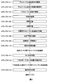
- step S101 the adjustment of the aluminum alloy component (step S101) to the strain relief heating process (step S110) are steps for manufacturing the aluminum alloy substrate for magnetic disk according to the present invention.
- step S111 the aluminum alloy substrate for magnetic disk is subjected to a pre-plating process (step S111) and a subsequent base (Ni-P) plating process (step S112), whereby the base-processed aluminum for magnetic disk of the present invention is applied.
- An alloy substrate is produced.
- the magnetic disk is manufactured by attaching a magnetic material to the surface of the aluminum alloy substrate for magnetic disk subjected to the ground treatment (step S113).
- a process for producing an aluminum alloy substrate for a magnetic disk will be described.
- the aluminum alloy melt having the above component composition is adjusted by heating and melting in accordance with a conventional method (step S101).
- step S102 the adjusted molten aluminum alloy is heated and held in a holding furnace (step S102).
- the heating temperature of the molten metal in the holding furnace is set to 700 to 850 ° C., so that the generation of Mg-based oxides and the generation of inclusions can be reduced.
- the heating temperature of the molten metal in the holding furnace is lower than 700 ° C., many inclusions are generated during holding, and even if the holding at such a temperature lower than 700 ° C. is performed for a long time, the inclusions are sufficiently removed. It cannot be performed and remains in the molten aluminum alloy. As a result, due to the inclusions, large depressions and grinding flaws are generated on the substrate surface, and the smoothness of the plating surface is lowered.
- the heating temperature of the molten metal in the holding furnace exceeds 850 ° C.
- a large amount of Mg-based oxide is generated, and when the plating process is performed, fine pits having a smaller size than conventional pits are frequently generated on the plating surface. Therefore, the heating temperature of the molten metal in the holding furnace is set to 700 to 850 ° C.
- the preferable heating temperature of the molten metal in the holding furnace is 750 to 850 ° C.
- the holding time of the molten metal in the holding furnace is 0.5 hours or more and less than 6.0 hours, thereby suppressing the formation of Mg-based oxides and inclusions that could not be completely dissolved in the molten metal (Ti-V- Zr—B particles, etc.) can be precipitated and removed.
- the holding time of the molten metal in the holding furnace is the time that the aluminum alloy molten metal adjusted in the melting furnace is all transferred to the holding furnace and is held after processing such as degassing is performed in the furnace. Say that. If the holding time of the molten metal in the holding furnace is less than 0.5 hours, the inclusions are not sufficiently precipitated and remain in the molten aluminum alloy.
- the molten metal holding time in the holding furnace is 0.5 hours or more and less than 6.0 hours.
- the holding time of the molten metal in a preferable holding furnace is 0.5 hour or more and 3.0 hours or less.
- in-line degassing processing or in-line filtration processing according to a conventional method.
- the in-line degassing apparatus those commercially available under trademarks such as SNIF and ALPUR can be used. These in-line degassing treatment apparatuses rotate a bladed rotating body at a high speed while blowing argon gas or a mixed gas such as argon and nitrogen into the molten metal and supply the gas as fine bubbles into the molten metal. Thereby, dehydrogenation gas and inclusions can be removed in-line in a short time.
- a ceramic tube filter, a ceramic foam filter, an alumina ball filter or the like is used, and inclusions are removed by a cake filtration mechanism or a filter medium filtration mechanism.
- the molten metal temperature at the start of casting is set to 700 to 850 ° C. similarly to the heating temperature of the molten metal in the holding furnace.
- the molten metal temperature at the start of casting is less than 700 ° C., many of the inclusions are generated before the start of casting. As a result, due to the inclusions, large depressions and grinding flaws are generated on the substrate surface, and the smoothness of the plating surface is lowered.
- the molten metal temperature at the start of casting exceeds 850 ° C.
- a large amount of Mg-based oxide is generated, and when plating is performed, fine pits having a size smaller than that of conventional pits are frequently generated on the plating surface. Therefore, the molten metal temperature at the start of casting is set to 700 to 850 ° C.
- a preferable molten metal temperature at the start of casting is 700 to 800 ° C.
- the time from the holding of the molten metal in the holding furnace to the start of casting (the time from the end of the molten metal holding process to the start of the casting process) is set to 0.3 hours or less, and the time from the holding of the molten metal to the start of casting. (Time from the start of the molten metal holding process to the start of the casting process) is set to 6.0 hours or less.
- the time from the holding of the molten metal in the holding furnace to the start of casting is set to 0.3 hours or less, and the time from the holding of the molten metal to the start of casting is set to 6.0 hours or less.
- the preferable time from the start of casting is 0.1 hour or less, and the preferable time from the molten metal holding to the start of casting is 3.1 hours or less.
- step S103 the molten aluminum alloy that has been heated and held is degassed, and an aluminum alloy is cast by a semi-continuous casting method (DC casting method), a continuous casting method (CC method), or the like.
- DC casting method semi-continuous casting method
- CC method continuous casting method
- the cast aluminum alloy ingot is homogenized (step S104).
- the homogenization treatment may not be performed, but when it is carried out, it is preferably performed at 480 to 560 ° C. for 1 hour or longer, more preferably at 500 to 550 ° C. for 2 hours or longer.
- the treatment temperature is less than 480 ° C. or when the treatment time is less than 1 hour, a sufficient homogenization effect may not be obtained.
- material may melt
- the cast aluminum alloy ingot, or the homogenized aluminum alloy ingot when the homogenization treatment is performed is made into a plate material by hot rolling (step S105).
- the hot rolling conditions are not particularly limited, but the hot rolling start temperature is preferably 300 to 500 ° C, more preferably 320 to 480 ° C. Further, the hot rolling end temperature is preferably 260 to 400 ° C., more preferably 280 to 380 ° C. If the hot rolling start temperature is less than 300 ° C., the hot rolling processability cannot be ensured, and if it exceeds 500 ° C., the crystal grains become coarse and the adhesion of the plating may decrease.
- the hot rolling end temperature is less than 260 ° C., the hot rolling processability cannot be ensured, and if it exceeds 400 ° C., the crystal grains are coarsened and the adhesion of plating may be lowered.
- the ingot is usually hot-rolled after being heated and held at the hot rolling start temperature for 0.5 to 10.0 hours. In the case of performing a homogenization process, the heating and holding may be replaced by a homogenization process.
- the hot-rolled sheet is cold-rolled to obtain an aluminum alloy sheet having a thickness of preferably 0.4 to 2.0 mm, more preferably 0.6 to 2.0 mm (step S106). That is, after completion of hot rolling, the product is finished to a required product thickness by cold rolling.
- the conditions for cold rolling are not particularly limited, and may be determined according to the required product plate strength and plate thickness.
- the rolling rate is preferably 20 to 90%, more preferably 20 to 80%. Is more preferable. If the rolling rate is less than 20%, the crystal grains may be coarsened by pressure flattening annealing, and the adhesion of the plating may be lowered. If the rolling rate exceeds 90%, the production time becomes longer and the productivity is lowered. May invite.
- an annealing treatment may be performed before cold rolling or in the middle of cold rolling.
- the annealing treatment is performed, for example, in the case of batch-type annealing, it is preferably performed at 300 to 450 ° C. for 0.1 to 10 hours, and at 300 to 380 ° C. for 1 to 5 hours. More preferred.
- the annealing temperature is less than 300 ° C. or when the annealing time is less than 0.1 hour, a sufficient annealing effect may not be obtained.
- the annealing temperature exceeds 450 ° C., the crystal grains become coarse and the adhesion of the plating may decrease, and when the annealing time exceeds 10 hours, the productivity decreases.
- the continuous annealing is preferably performed at 400 to 500 ° C. for 0 to 60 seconds and more preferably at 450 to 500 ° C. for 0 to 30 seconds.
- the annealing temperature is less than 400 ° C., a sufficient annealing effect may not be obtained.
- the annealing temperature exceeds 500 ° C., the crystal grains become coarse and the adhesion of the plating may be lowered.
- the annealing time exceeds 60 seconds, the crystal grains become coarse and the plating adheres. May decrease.
- 0 second in this case means cooling immediately after reaching a desired annealing temperature.
- the aluminum alloy plate is punched into an annular shape to produce an annular aluminum alloy plate (step S107).
- the annular aluminum alloy plate is subjected to pressure flattening annealing at 300 to 450 ° C. for 30 minutes or more, preferably at 300 to 380 ° C. for 60 minutes or more in the air, and a flattened disc blank is produced (step) S108). If the treatment temperature is less than 300 ° C. or the treatment time is less than 30 minutes, the planarization effect may not be obtained. When the processing temperature exceeds 450 ° C., the crystal grains become coarse and the adhesion of the plating may decrease.
- the pressurization is usually performed under a pressure of 1.0 to 3.0 MPa.
- step S109 After the flattened disc blank is subjected to cutting and grinding (step S109), a heat treatment (step S110) for removing distortion of the disc blank is performed.
- the temperature increase rate is 20.0 ° C./min or more.
- This rate of temperature rise is preferably 30.0 ° C./min or more.
- the upper limit of the rate of temperature increase is not particularly limited, but depends on the heating capability of the apparatus, and in the present invention, it is preferably 60.0 ° C./min. Further, the reason for setting the temperature rising rate as being from 150 ° C. is that even if it is kept for a long time in a temperature range of less than 150 ° C., the concentration of Be is not greatly affected.
- the holding temperature in the heat treatment is less than 200 ° C.
- the processing strain is not removed, so that the substrate is deformed during heating after the plating treatment (for example, during heating of magnetic sputtering) and cannot be used as a magnetic disk.
- the holding temperature exceeds 400 ° C.
- the Al / Mg / Be oxide on the surface layer of the aluminum alloy substrate becomes thick, so that the Al / Mg / Be oxide remains without being completely removed by the plating pretreatment. , Frequent fine pits. Therefore, the holding temperature is set to 200 to 400 ° C.
- a preferable holding temperature is 200 to 290 ° C.
- the holding time at the holding temperature is less than 5 minutes, the processing strain is not removed, so that the substrate is deformed during heating after the plating process (for example, heating of magnetic sputtering) and cannot be used as a magnetic disk.
- the holding time exceeds 15 minutes, the Al / Mg / Be oxide on the surface layer of the aluminum alloy substrate becomes thick, so that the Al / Mg / Be oxide remains without being completely removed by the pretreatment for plating. , Frequent fine pits. Therefore, the holding time is 5 to 15 minutes.
- a preferable holding time is 5 to 10 minutes.
- the temperature lowering rate from the holding temperature in the range of 200 to 400 ° C. to 150 ° C. is less than 20.0 ° C./min during cooling and cooling in the strain relief heat treatment, the Al / Mg / Be in the aluminum alloy substrate surface layer is used. The oxide becomes thicker. As a result, the Al / Mg / Be oxide is not completely removed by the plating pretreatment, and fine pits are frequently generated. Therefore, the temperature lowering rate is 20.0 ° C./min or more.
- the temperature lowering rate is preferably 30.0 ° C./min or more.
- the upper limit value of the temperature lowering rate is not particularly limited and depends on the cooling capacity of the apparatus, but is preferably 60.0 ° C./min in the present invention.
- the temperature decreasing rate is defined as being up to 150 ° C.
- the aluminum alloy substrate for magnetic disk according to the present invention is produced.
- the aluminum alloy substrate for a magnetic disk manufactured as described above is subjected to degreasing, etching, and zincate treatment (Zn substitution treatment) as plating pretreatment (step S111).
- Degreasing is preferably performed using a commercially available AD-68F (manufactured by Uemura Kogyo Co., Ltd.) degreasing solution at a temperature of 40 to 70 ° C., a treatment time of 3 to 10 minutes, and a concentration of 200 to 800 mL / L. More preferably, it is carried out under the conditions of 65 ° C., treatment time of 4 to 8 minutes, and concentration of 300 to 700 mL / L. When the temperature is less than 40 ° C., when the treatment time is less than 3 minutes, or when the concentration is less than 200 mL / L, a sufficient degreasing effect may not be obtained.
- AD-68F manufactured by Uemura Kogyo Co., Ltd.
- Etching is preferably performed using a commercially available AD-107F (manufactured by Uemura Kogyo) etching solution under the conditions of a temperature of 50 to 75 ° C., a treatment time of 0.5 to 5 minutes, and a concentration of 20 to 100 mL / L. More preferably, it is carried out under conditions of 55 to 70 ° C., a treatment time of 0.5 to 3 minutes, and a concentration of 40 to 100 mL / L.
- the temperature is less than 50 ° C.
- the treatment time is less than 0.5 minutes, or when the concentration is less than 20 mL / L, a sufficient etching effect may not be obtained.
- the zincate treatment is carried out using a commercially available AD-301F-3X (manufactured by Uemura Kogyo Co., Ltd.) zincate treatment solution, etc. under conditions of a temperature of 10 to 35 ° C., a treatment time of 0.1 to 5 minutes, and a concentration of 100 to 500 mL / L. It is more preferable to carry out under conditions of a temperature of 15 to 30 ° C., a treatment time of 0.1 to 2 minutes, and a concentration of 200 to 400 mL / L.
- AD-301F-3X manufactured by Uemura Kogyo Co., Ltd.
- the temperature is less than 10 ° C.
- the treatment time is less than 0.1 minutes, or when the concentration is less than 100 mL / L
- the zincate film becomes non-uniform, and conventional pits are generated after the plating process, resulting in smoothness. May decrease.
- the temperature exceeds 35 ° C when the processing time exceeds 5 minutes, or when the concentration exceeds 500 mL / L, the zincate film becomes non-uniform, and conventional pits are generated after the plating process, resulting in reduced smoothness. There are things to do.
- the surface of the aluminum alloy substrate that has been subjected to zincate treatment is subjected to electroless Ni—P plating treatment as a base treatment, and then the surface is polished (step S112).
- the electroless Ni—P plating treatment uses a commercially available Nimuden HDX (manufactured by Uemura Kogyo) plating solution, etc., under conditions of a temperature of 80 to 95 ° C., a treatment time of 30 to 180 minutes, and a Ni concentration of 3 to 10 g / L.
- the treatment is preferably carried out, more preferably under the conditions of a temperature of 85 to 95 ° C., a treatment time of 60 to 120 minutes, and a Ni concentration of 4 to 9 g / L.
- the temperature is less than 80 ° C. or the Ni concentration is less than 3 g / L
- the growth rate of the plating is slow, which may cause a decrease in productivity.
- the treatment time is less than 30 minutes, defects are likely to occur on the plating surface, and the smoothness of the plating surface may be reduced.
- the temperature exceeds 95 ° C. or when the Ni concentration exceeds 10 g / L
- the plating grows unevenly, so that the smoothness of the plating may be reduced.
- productivity may be reduced.
- the ground-treated aluminum alloy substrate for magnetic disks of the present invention can be obtained.
- a magnetic material is attached by sputtering to the surface subjected to the base plating process to form a magnetic disk (step S113).
- each of the above-mentioned processes is related to the formation of Mg-based oxides and the oxidation of Be on the surface layer.
- the characteristics of the aluminum alloy substrate for magnetic disks according to the present invention include the step of heating and holding the molten aluminum alloy in step S102, It is particularly affected by the casting stage of step S103 and the strain relief heating process of step S110.
- the molten aluminum alloy in order to regulate the amount of Mg-based oxide, the molten aluminum alloy is kept in the holding furnace at a holding temperature in the range of 700 to 850 ° C. for 0.5 hour or more. 6.
- the time from the end of the molten metal holding process to the start of the casting process is 0.3 hours or less, and the time from the start of the molten metal holding process to the start of the casting process is 6. Perform in 0 hours or less.
- the casting process is performed at a molten metal temperature of 700 to 850 ° C. at the start of casting.
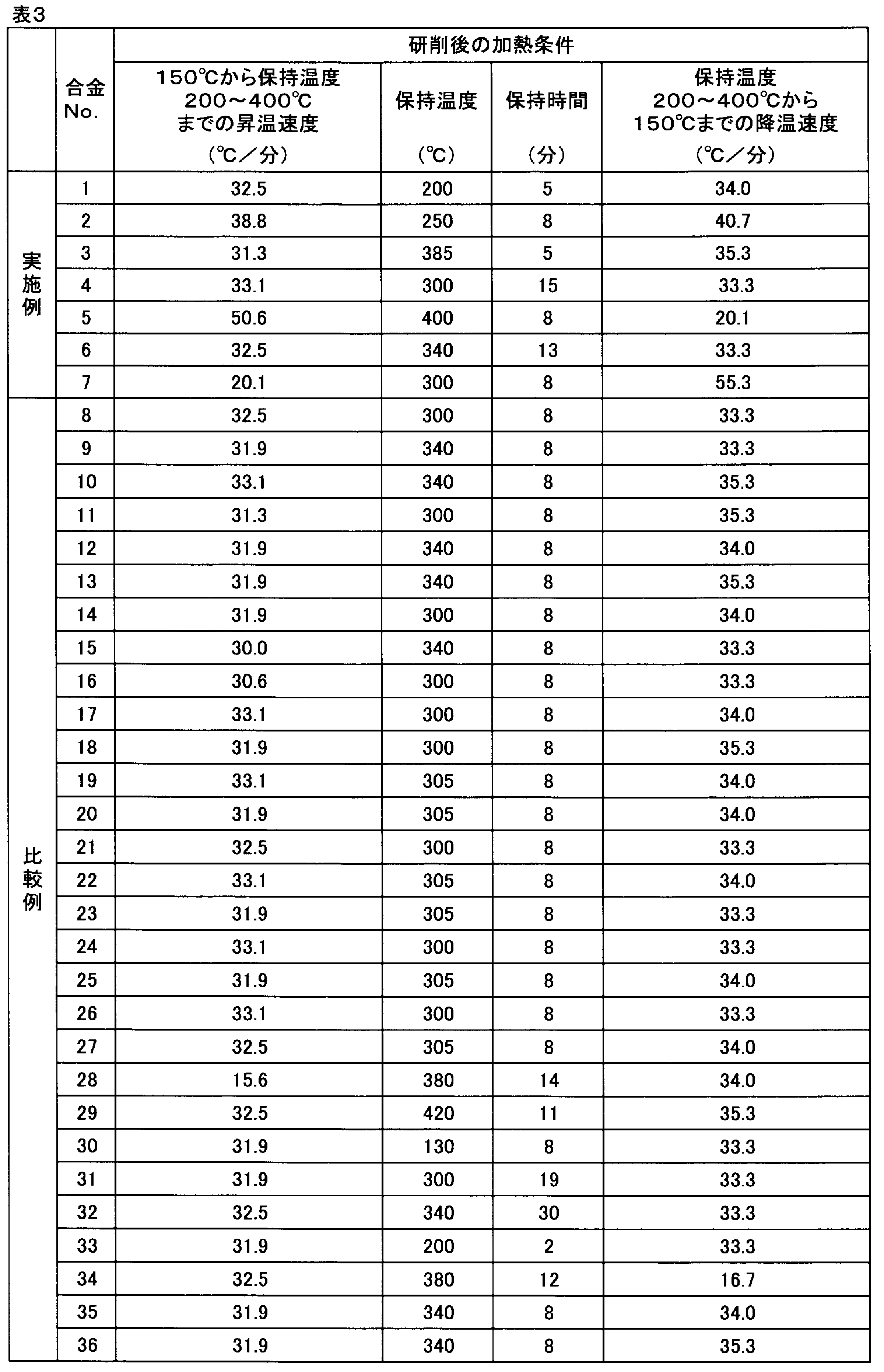
- the temperature is increased by 20.0 ° C./min or more from 150 ° C.
- a cooling and cooling step for cooling the blank is included.
- each alloy having the component composition shown in Table 1 was melted in accordance with a conventional method, and a molten aluminum alloy was melted (step S101).
- step S102 the molten aluminum alloy was heated and held in a holding furnace under the conditions shown in Table 2 (step S102).
- step S103 the molten aluminum alloy heated was cast by a semi-continuous casting method (DC casting method) to produce an ingot (step S103).
- step S106 The aluminum alloy plate thus obtained was punched into an annular shape having an outer diameter of 96 mm and an inner diameter of 24 mm to produce an annular aluminum alloy plate (step S107).
- the annular aluminum alloy plate obtained as described above was subjected to pressure flattening annealing at 400 ° C. for 3 hours under a pressure of 1.5 MPa to obtain a disk blank (step S108). Further, the end surface of the disc blank was ground to an outer diameter of 95 mm and an inner diameter of 25 mm, and further, a grinding process (grinding process) for grinding the surface by 10 ⁇ m was performed (step S109). Next, it heated on the conditions of Table 3 and was set as the aluminum alloy board
- the surface of the aluminum alloy substrate for magnetic disk was degreased by immersing it in AD-68F (manufactured by Uemura Kogyo) at 60 ° C. for 5 minutes (concentration: 550 mL / L).
- AD-68F manufactured by Uemura Kogyo
- the surface was etched by being immersed in an AD-107F (Uemura Kogyo) etching solution (concentration: 70 mL / L) at 65 ° C. for 1 minute.
- the surface was desmutted by dipping in a 30% aqueous HNO 3 solution at room temperature for 20 seconds.
- the aluminum alloy substrate was immersed in a 20 ° C. zincate treatment solution (concentration: 300 mL / L) of AD-301F-3X (manufactured by Uemura Kogyo Co., Ltd.) for 0.5 minutes to form a zincate on the surface. Processing was performed (step S111).
- the zincate treatment was performed twice in total, and the surface was exfoliated by immersing in a 30% aqueous HNO3 solution at room temperature for 20 seconds between the zincate treatments. As described above, the plating pretreatment was completed.
- Ni—P plating layer was formed on the surface of the zincate-treated aluminum alloy substrate using an electroless Ni—P plating treatment solution (Nimden HDX (manufactured by Uemura Kogyo), Ni concentration: 7 g / L). Electroless plating was applied as shown. The electroless Ni—P plating treatment was performed at a temperature of 92 ° C. and a treatment time of 160 minutes. Finally, the plated surface was finish-polished with a blanket with a polishing amount of 6 ⁇ m (step S112). In this way, an aluminum alloy substrate for a magnetic disk subjected to a ground treatment was obtained.
- step S106 Aluminum alloy plate after cold rolling process (step S106), aluminum alloy substrate for magnetic disk after heat removal after grinding process (step S110), and base (Ni-P) plating process (with polishing) (step) S112)
- step S112 The following evaluation was performed on the aluminum alloy substrate for a magnetic disk subjected to the ground treatment after that.
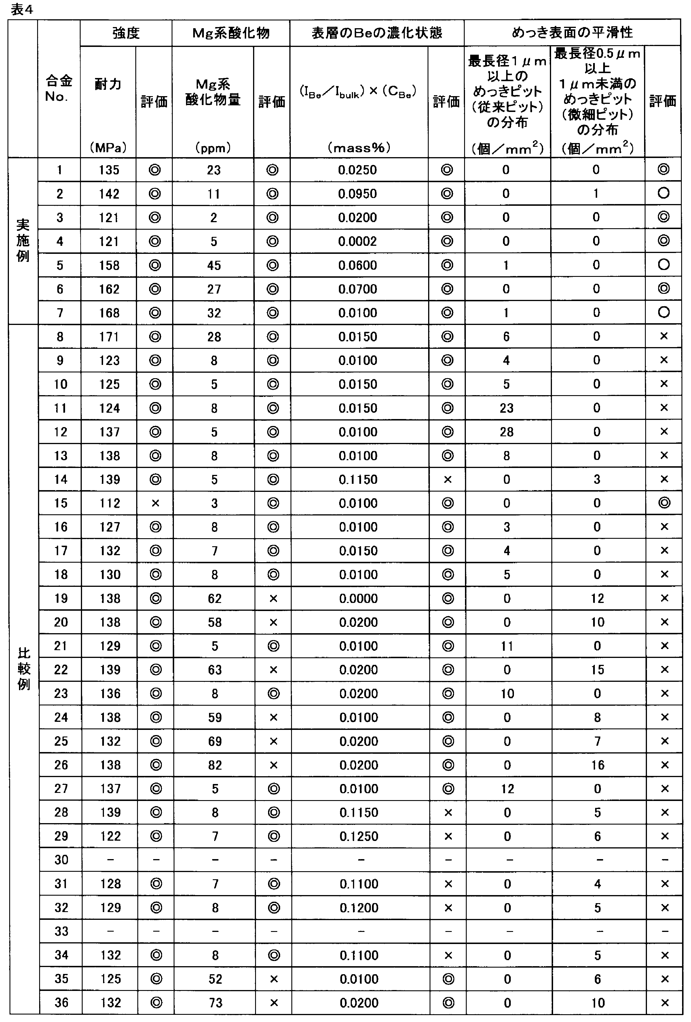
- Table 4 alloy no. In Comparative Example 30 using No. 30, the temperature during heating after grinding was low, so In Comparative Example 33 using 33, the holding time during heating after grinding was short, so that none of the processing strain was completely removed. As a result, the substrate was deformed during heating after the plating treatment, and the constituent requirements for “for magnetic disk” could not be satisfied. Therefore, the following evaluation was not performed (see Table 4).
- Mg-based oxide content of aluminum alloy substrate for magnetic disk The amount of Mg-based oxide of the aluminum alloy substrate for magnetic disk after the strain relief heat treatment (step S110) was measured by the iodine methanol method, that is, the oxide extraction method. As evaluation criteria, Mg-based oxides having an amount of 50 ppm or less were judged as excellent ( ⁇ ), and those exceeding 50 ppm were judged as bad (x). The results are shown in Table 4.
- the maximum peak height of Be when sputtering from the surface of the measurement sample to a depth of 2.0 ⁇ m was defined as the maximum emission intensity. Further, the average height of Be when the depth from the surface of the measurement sample was 1.5 to 2.0 ⁇ m was defined as the average intensity.
- the product, that is, (I Be / I bulk ) ⁇ (C Be ) of 0.1000% or less was judged as excellent ( ⁇ ), and the product exceeding 0.1000% was judged as defective ( ⁇ ).
- the results are shown in Table 4.
- step S112 The number of conventional pits and fine pits on the surface of the aluminum alloy substrate for a magnetic disk, which was ground and treated after Ni-P plating treatment (step S112), was determined.
- the number of conventional pits having a longest diameter of 1 ⁇ m or more is measured with an optical microscope at a magnification of 1000 ⁇ with an observation field of 1 mm 2, and the number per unit area (number density: pieces / mm 2 ). Asked.
- the number of fine pits having a longest diameter of 0.5 ⁇ m or more and less than 1 ⁇ m was measured by SEM with an observation field of 1 mm 2 at a magnification of 2000 times, and the number per unit area (number density: pieces / piece mm 2 ) was determined.
- the longest diameter of both conventional pits and fine pits refers to the largest of those observed as the length of each pit.
- the upper limit of the longest diameter of a conventional pit is not limited, a thing of 10 micrometers or more was not observed.
- the fine pits those with the longest diameter of less than 0.5 ⁇ m were not observed, and thus were excluded.
- both the conventional pits and the fine pits were counted as one in which only a part of the pits was observed as well as the entire pits existing in the 1 mm 2 observation field.
- the case is excellent ( ⁇ mark), and when one or both are 1 / mm 2 , the case is good ( ⁇ mark). Or the case where both were 2 pieces / mm ⁇ 2 > or more was made into the defect (x mark).
- Table 4 The results are shown in Table 4.
- Comparative Example 8 since there was too much Mg content, a large amount of coarse Al—Mg-based intermetallic compound was generated, and this intermetallic compound dropped off during the pre-plating process, and a large depression was generated on the surface of the aluminum alloy substrate. did. As a result, conventional pits were likely to occur on the plating surface, resulting in poor plating surface smoothness.
- Comparative Example 9 since there was too much Cu content, a large amount of coarse Al—Cu—Mg—Zn-based intermetallic compound was generated, and this intermetallic compound dropped off during the pre-plating treatment, and a large depression was formed on the surface of the aluminum alloy substrate. There has occurred. As a result, conventional pits were likely to occur on the plating surface, resulting in poor plating surface smoothness.
- Comparative Example 10 since there was too much Zn content, a large amount of coarse Al—Cu—Mg—Zn-based intermetallic compound was generated, and this intermetallic compound dropped off during the plating pretreatment, and a large depression was formed on the surface of the aluminum alloy substrate. There has occurred. As a result, conventional pits were likely to occur on the plating surface, resulting in poor plating surface smoothness.
- Comparative Example 11 since there was too much Cr content, a large amount of coarse Al—Cr intermetallic compound was produced, and this intermetallic compound dropped off during the pre-plating treatment, and a large depression was generated on the surface of the aluminum alloy substrate. As a result, conventional pits were likely to occur on the plating surface, resulting in poor plating surface smoothness.
- Comparative Example 12 since there was too much Fe content, a large amount of coarse Al—Fe-based intermetallic compound was produced, and this intermetallic compound dropped off during the pre-plating treatment, and a large depression was generated on the surface of the aluminum alloy substrate. As a result, conventional pits were likely to occur on the plating surface, resulting in poor plating surface smoothness.
- Comparative Example 13 since the Si content was too large, a large amount of coarse Mg—Si intermetallic compound was produced, and this intermetallic compound dropped off during the pre-plating treatment, and a large depression was generated on the surface of the aluminum alloy substrate. As a result, conventional pits were likely to occur on the plating surface, resulting in poor plating surface smoothness.
- Comparative Example 19 a large amount of Mg-based oxide was generated because the Be content was too small. As a result, fine pits were easily generated on the plating surface, and the smoothness of the plating surface was poor.
- Comparative Example 20 a large amount of Mg-based oxide was produced because the heating temperature of the molten metal in the holding furnace was too high. As a result, fine pits were easily generated on the plating surface, and the smoothness of the plating surface was poor.
- Comparative Example 26 a large amount of Mg-based oxide was generated because the heating temperature of the molten metal in the holding furnace and the molten metal temperature at the start of casting were too high. As a result, fine pits were easily generated on the plating surface, and the smoothness of the plating surface was poor.
- Comparative Example 27 since the molten metal temperature at the start of casting was too low, a lot of coarse inclusions were generated, and many large dents and grinding flaws were generated on the surface of the aluminum alloy plate during grinding and plating pretreatment. As a result, conventional pits were likely to occur on the plating surface, resulting in poor plating surface smoothness.
- Comparative Example 36 a lot of Mg-based oxide was generated because the molten metal holding time in the holding furnace, the time from the end of the molten metal holding process to the start of casting, and the time from the start of the molten metal holding process to the start of casting were too long. As a result, fine pits were easily generated on the plating surface, and the smoothness of the plating surface was poor.
- the present invention can provide a magnetic disk aluminum alloy substrate having excellent smoothness and strength of the plating surface and a ground-treated aluminum alloy substrate for a magnetic disk, and is excellent in industrial applicability.
Landscapes
- Engineering & Computer Science (AREA)
- Chemical & Material Sciences (AREA)
- Metallurgy (AREA)
- Mechanical Engineering (AREA)
- Inorganic Chemistry (AREA)
- Materials Engineering (AREA)
- Organic Chemistry (AREA)
- Physics & Mathematics (AREA)
- Thermal Sciences (AREA)
- Crystallography & Structural Chemistry (AREA)
- Magnetic Record Carriers (AREA)
- Manufacturing Of Magnetic Record Carriers (AREA)
Abstract
Description
まず、本発明の実施形態に係る磁気ディスク用アルミニウム合金基板を構成するアルミニウム合金成分について説明する。
Mgは、主としてアルミニウム合金基板の強度を向上させる効果を有する。また、Mgは、ジンケート処理時のジンケート皮膜を均一に、薄く、かつ、緻密に付着させる作用を奏するので、ジンケート処理工程の次工程である下地めっき処理工程において、Ni-Pからなるめっき表面の平滑性が向上する。Mgの含有量は4.5~10.0mass%(以下、単に「%」と記す)である。Mgの含有量が4.5%未満では強度が不十分であり、10.0%を超えると粗大なMg-Si系化合物が生成し、エッチング時、ジンケート処理時、切削や研削の加工時に粗大なMg-Si系化合物が脱落して、めっき表面に大きなピット(従来ピット)が発生する。その結果、めっき表面の平滑性が低下する。好ましいMgの含有量は、強度および製造の容易さの兼合いから4.5~7.0%である。
Beは鋳造時に、Mgの溶湯酸化を抑制する効果と材料自体の耐食性を向上させる効果を有する。しかしながら、Beの添加量が多いと、切削加工・研削加工の後の歪取り加熱処理においてBeが表層に濃化し、Beを含有するAl/Mg/Be酸化物が形成される。そして、これにめっき処理を行うと、めっき表面に従来ピットよりもサイズが小さい微細ピットが多発することが判明した。これは、Beを含有するAl/Mg/Be酸化物がBeを含有しないAl/Mg酸化物に比べて耐食性が高いことに関係していると考えられる。すなわち、Al/Mg/Be酸化物はその高耐食性によって、エッチングなどのめっき前処理によっては除去され難いためと考えられる。
Cuはジンケート処理時のAl溶解量を減少させ、またジンケート皮膜を均一に、薄く、緻密に付着させる効果を有する。その結果、次工程の下地めっき処理で形成されるNi-Pからなるめっき表面の平滑性を向上させる。Cuの含有量は、0.003~0.150%とする。Cu含有量が0.003%未満では上記効果が十分に得られない。一方、Cu含有量が0.150%を超えると粗大なAl-Cu-Mg-Zn系金属間化合物が生成して、めっき処理後における従来ピットが発生し平滑性が低下する。更に、材料自体の耐食性を低下させるため、ジンケート処理により生成するジンケート皮膜が不均一となり、めっきの密着性や平滑性が低下する。好ましいCu含有量は、0.005~0.100%である。
ZnはCuと同様にジンケート処理時のAl溶解量を減少させ、またジンケート皮膜を均一に、薄く、緻密に付着させ、次工程の下地めっき処理で形成されるNi-Pからなるめっき表面の平滑性を向上させる効果を有する。Znの含有量は、0.05~0.60%とする。Zn含有量が0.05%未満では上記効果が十分に得られない。一方、Zn含有量が0.60%を超えると、粗大なAl-Cu-Mg-Zn系金属間化合物が生成して、めっき処理後における従来ピットが発生し平滑性が低下する。更に、材料自体の加工性や耐食性を低下させる。好ましいZn含有量は、0.05~0.50%である。
Crは鋳造時に微細な金属間化合物を生成するが、一部はマトリックスに固溶して強度向上に寄与する。また切削性と研削性を高め、更に再結晶組織を微細にして、めっき層の密着性を向上させる効果を有する。Crの含有量は、0.010~0.300%とする。Cr含有量が0.010%未満では、上記効果が十分に得られない。一方、Cr含有量が0.300%を超えると、鋳造時において過剰分が晶出すると同時に粗大なAl-Cr系金属間化合物が生成し、エッチング時、ジンケート処理時、切削や研削の加工時に粗大なAl-Cr系金属間化合物が脱落して、めっき表面に大きな従来ピットが発生し、めっき表面の平滑性が低下する。好ましいCr含有量は、0.010~0.200%である。
Siは本発明の必須元素であるMgと結合し、めっき層において欠陥となる金属間化合物を生成するため、アルミニウム合金中にSiが含有されることは好ましくない。Siの含有量が0.060%を超えると、粗大なMg-Si系金属間化合物が生成して従来ピットなどの発生原因になる。従って、Si含有量を0.060%以下に規制する。Si含有量は、0.025%未満に規制するのが好ましく、0%が最も好ましい。
Feはアルミニウム中には殆ど固溶せず、Al-Fe系金属間化合物としてアルミニウム地金中に存在する。このアルミニウム中に存在するFeは本発明の必須元素であるAlと結合し、めっき層において欠陥となる金属間化合物を生成するため、アルミニウム合金中にFeが含有されることは好ましくない。Feの含有量が0.060%を超えると、粗大なAl-Fe系金属間化合物が生成して従来ピットなどの発生原因になる。従って、Fe含有量を0.060%以下に規制する。Fe含有量は、0.025%未満に規制するのが好ましく、0%が最も好ましい。
また、本発明の実施形態に係るアルミニウム合金の残部は、アルミニウムと不可避的不純物とからなる。ここで、不可避的不純物(例えばMn等)は、各々が0.03%以下で、かつ、合計で0.15%以下であれば、本発明で得られるアルミニウム合金基板としての特性を損なうことはない。
次に、本発明に係る磁気ディスク用アルミニウム合金基板の表層のBeの濃化状態について説明する。
次に、本発明に係る磁気ディスク用アルミニウム合金基板中のMg系酸化物の含有量について説明する。
以下に、本発明に係る磁気ディスク用アルミニウム合金基板の製造工程について詳細に説明する。


冷間圧延工程(ステップS106)の後におけるアルミニウム合金板を400℃で3時間の条件で加熱した後、圧延方向に沿って切り出したJIS5号試験片の耐力(圧延方向に沿った方向における)を、島津製作所製インストロン型引張試験機AG-50kNGを使用して測定した。測定条件は、標点距離50mm、クロスヘッド速度10mm/分とした。評価基準としては、耐力120MPa以上のものを優良(◎印)とし、耐力120MPa未満のものを不良(×印)とした。結果を表4に示す。
歪取り加熱処理(ステップS110)の後における磁気ディスク用アルミニウム合金基板のMg系酸化物量をヨウ素メタノール法、すなわち酸化物抽出法により測定した。評価基準としては、Mg系酸化物量が50ppm以下のものを優良(◎印)とし、50ppmを超えるものを不良(×印)とした。結果を表4に示す。
歪取り加熱処理(ステップS110)の後における磁気ディスク用アルミニウム合金基板の表面の深さ方向に沿ったBeをGDS分析した。具体的には、上記のようにBeの最大発光強度及び母材内部の平均Be強度を測定して、アルミニウム合金基板の表層におけるBeの酸化状態を評価した。GDS分析は、株式会社堀場製作所製のJY-5000RFの装置を用い実施した。GDSの測定条件は、アルゴンガス置換後の圧力600Pa、出力30W、モジュール700、フェーズ300、アノード径4mmφとした。測定試料の表面から深さ2.0μmまでスパッタする際におけるBeの最大ピーク高さを最大発光強度とした。また、測定試料の表面からの深さが1.5~2.0μmの間におけるBeの平均高さを平均強度とした。このようにして測定したBeの最大発光強度(IBe)と、アルミ合金板母材内部の平均Be強度(Ibulk)との比(IBe/Ibulk)とBe濃度(CBe)との積、すなわち、(IBe/Ibulk)×(CBe)が0.1000%以下のものを優良(◎印)とし、0.1000%を超えるものを不良(×印)とした。結果を表4に示す。
Ni-Pめっき処理して研磨(ステップS112)後の下地処理した磁気ディスク用アルミニウム合金基板表面における従来ピット及び微細ピットの個数を求めた。従来ピットについては、光学顕微鏡により1000倍の倍率で観察視野を1mm2とし、最長径1μm以上の大きさの従来ピットの個数を計測し、単位面積当たりの個数(個数密度:個/mm2)を求めた。微細ピットについては、SEMにより2000倍の倍率で観察視野を1mm2とし、最長径0.5μm以上1μm未満の大きさの微細ピットの個数を測定し、単位面積当たりの個数(個数密度:個/mm2)を求めた。ここで、従来ピット及び微細ピット共に最長径とは、各ピットの長さとして観察されるもののうち最大のものをいう。また、従来ピットの最長径の上限は限定されるものではないが、10μm以上のものは観察されなかった。微細ピットでは、最長径が0.5μm未満のものは観察されなかったので対象外とした。なお、従来ピット及び微細ピット共に、1mm2の観察視野中にピットの全体が存在している場合は勿論、ピットの一部のみが観察されたものも一個として数えた。評価基準としては、従来ピット及び微細ピットの個数密度が共に0個/mm2の場合を優良(◎印)とし、一方又は両方が1個/mm2の場合を良好(○印)とし、一方又は両方が2個/mm2以上の場合を不良(×印)とした。結果を表4に示す。
Claims (3)
- Mg:4.5~10.0mass%、Be:0.00001~0.00200mass%、Cu:0.003~0.150mass%、Zn:0.05~0.60mass%、Cr:0.010~0.300mass%を含有し、Si:0.060mass%以下及びFe:0.060mass%以下に規制し、残部Al及び不可避的不純物からなるアルミニウム合金からなり、Mg系酸化物の含有量が50ppm以下であり、めっき前処理を施す前において、グロー放電発光分析装置(GDS)による表面深さ方向におけるBeの最大発光強度を(IBe)とし、アルミニウム合金の母材内部におけるBeの平均発光強度を(Ibulk)とし、上記Be含有量を(CBe)mass%として、(IBe/Ibulk)×(CBe)≦0.1000mass%であることを特徴とする磁気ディスク用アルミニウム合金基板。
- 請求項1に記載の磁気ディスク用アルミニウム合金基板の製造方法であって、前記アルミニウム合金の溶湯を調整する調整工程と、調整した前記アルミニウム合金の溶湯を加熱保持する溶湯保持工程と、加熱保持した溶湯を鋳造する鋳造工程と、鋳塊を熱間圧延する熱間圧延工程と、熱間圧延板を冷間圧延する冷間圧延工程と、冷間圧延板を円環状ディスクに加工する加工工程と、円環状ディスクを加圧平坦化してディスクブランクとする加圧平坦化焼鈍工程と、ディスクブランクを切削・研削する切削・研削工程と、切削・研削したディスクブランクの歪取り加熱処理工程とを含み、前記溶湯保持工程において、前記アルミニウム合金の溶湯を保持炉中において700~850℃の範囲にある保持温度で0.5時間以上6.0時間未満加熱保持し、前記溶湯保持工程終了から前記鋳造工程開始までの時間が0.3時間以下であり、かつ前記溶湯保持工程開始から前記鋳造工程開始までの時間が6.0時間以下であり、前記鋳造工程において、鋳造開始時の溶湯温度を700~850℃として溶湯を鋳造し、前記歪取り加熱処理工程において、150℃から200~400℃の範囲にある保持温度まで20.0℃/分以上の昇温速度でディスクブランクを加熱する加熱昇温段階と、前記保持温度において5~15分間ディスクブランクを加熱保持する加熱保持段階と、前記保持温度から150℃まで20.0℃/分以上の降温速度でディスクブランクを冷却する冷却降温段階とを含むことを特徴とする磁気ディスク用アルミニウム合金基板の製造方法。
- 請求項1に記載の磁気ディスク用アルミニウム合金基板に、めっきと磁性体が設けられていることを特徴とする磁気ディスク。
Priority Applications (2)
| Application Number | Priority Date | Filing Date | Title |
|---|---|---|---|
| CN201680039666.5A CN107835863B (zh) | 2015-07-28 | 2016-07-27 | 磁盘用铝合金基板及其制造方法 |
| US15/747,681 US20180221928A1 (en) | 2015-07-28 | 2016-07-27 | Magnetic disc aluminum alloy substrate and manufacturing method therefor |
Applications Claiming Priority (4)
| Application Number | Priority Date | Filing Date | Title |
|---|---|---|---|
| JP2015148298 | 2015-07-28 | ||
| JP2015-148298 | 2015-07-28 | ||
| JP2016-143017 | 2016-07-21 | ||
| JP2016143017A JP6807142B2 (ja) | 2015-07-28 | 2016-07-21 | 磁気ディスク用アルミニウム合金基板及びその製造方法 |
Publications (1)
| Publication Number | Publication Date |
|---|---|
| WO2017018451A1 true WO2017018451A1 (ja) | 2017-02-02 |
Family
ID=57885562
Family Applications (1)
| Application Number | Title | Priority Date | Filing Date |
|---|---|---|---|
| PCT/JP2016/072027 Ceased WO2017018451A1 (ja) | 2015-07-28 | 2016-07-27 | 磁気ディスク用アルミニウム合金基板及びその製造方法 |
Country Status (1)
| Country | Link |
|---|---|
| WO (1) | WO2017018451A1 (ja) |
Cited By (1)
| Publication number | Priority date | Publication date | Assignee | Title |
|---|---|---|---|---|
| CN113832374A (zh) * | 2021-08-13 | 2021-12-24 | 河南明泰铝业股份有限公司 | 一种5a12铝合金热轧坯料及其生产方法 |
Citations (3)
| Publication number | Priority date | Publication date | Assignee | Title |
|---|---|---|---|---|
| JPS6254053A (ja) * | 1985-09-02 | 1987-03-09 | Sumitomo Light Metal Ind Ltd | メツキ性とメツキ層の密着性にすぐれメツキ欠陥の少ない磁気デイスク用アルミニウム合金 |
| JPH11315338A (ja) * | 1998-05-07 | 1999-11-16 | Sumitomo Light Metal Ind Ltd | ジンケート処理性に優れた磁気ディスク用アルミニウム合金 |
| JP2013023737A (ja) * | 2011-07-22 | 2013-02-04 | Furukawa-Sky Aluminum Corp | 磁気ディスク用アルミニウム合金基板及びその製造方法 |
-
2016
- 2016-07-27 WO PCT/JP2016/072027 patent/WO2017018451A1/ja not_active Ceased
Patent Citations (3)
| Publication number | Priority date | Publication date | Assignee | Title |
|---|---|---|---|---|
| JPS6254053A (ja) * | 1985-09-02 | 1987-03-09 | Sumitomo Light Metal Ind Ltd | メツキ性とメツキ層の密着性にすぐれメツキ欠陥の少ない磁気デイスク用アルミニウム合金 |
| JPH11315338A (ja) * | 1998-05-07 | 1999-11-16 | Sumitomo Light Metal Ind Ltd | ジンケート処理性に優れた磁気ディスク用アルミニウム合金 |
| JP2013023737A (ja) * | 2011-07-22 | 2013-02-04 | Furukawa-Sky Aluminum Corp | 磁気ディスク用アルミニウム合金基板及びその製造方法 |
Cited By (1)
| Publication number | Priority date | Publication date | Assignee | Title |
|---|---|---|---|---|
| CN113832374A (zh) * | 2021-08-13 | 2021-12-24 | 河南明泰铝业股份有限公司 | 一种5a12铝合金热轧坯料及其生产方法 |
Similar Documents
| Publication | Publication Date | Title |
|---|---|---|
| JP6807142B2 (ja) | 磁気ディスク用アルミニウム合金基板及びその製造方法 | |
| JP6427267B2 (ja) | 磁気ディスク用アルミニウム合金基板及びその製造方法、ならびに、当該磁気ディスク用アルミニウム合金基板を用いた磁気ディスク | |
| JP5762612B1 (ja) | 磁気ディスク基板用アルミニウム合金板及びその製造方法、ならびに、磁気ディスクの製造方法 | |
| JP6998305B2 (ja) | 磁気ディスク基板用アルミニウム合金板及びその製造方法、並びに磁気ディスク | |
| JP5767384B1 (ja) | 磁気ディスク用アルミニウム合金板、磁気ディスク用アルミニウム合金ブランク及び磁気ディスク用アルミニウム合金サブストレート | |
| JP5901168B2 (ja) | 磁気ディスク用アルミニウム合金基板及びその製造方法、ならびに、下地処理磁気ディスク用アルミニウム合金基板及びその製造方法 | |
| WO2018092547A1 (ja) | 磁気ディスク用アルミニウム合金基板及びその製造方法 | |
| JP6990290B1 (ja) | 磁気ディスク用アルミニウム合金ディスクブランク及び磁気ディスク | |
| JP2017110273A (ja) | 磁気ディスク基板用アルミニウム合金基板及びその製造方法、ならびに、当該アルミニウム合金基板を用いた磁気ディスクの製造方法 | |
| JP6998499B1 (ja) | 磁気ディスク用アルミニウム合金基板、ならびに、当該磁気ディスク用アルミニウム合金基板を用いた磁気ディスク | |
| JP2023032363A (ja) | 磁気ディスク用アルミニウム合金鋳塊の製造方法、このアルミニウム合金鋳塊を用いた磁気ディスク用アルミニウム合金板の製造方法、このアルミニウム合金板を用いた磁気ディスク用アルミニウム合金基板の製造方法、ならびに、このアルミニウム合金基板を用いた磁気ディスク | |
| JP2005344173A (ja) | 磁気ディスク用アルミニウム合金基板およびその製造方法 | |
| WO2025047937A1 (ja) | アルミニウム合金ディスク材、アルミニウム合金原料の製造方法、アルミニウム合金鋳塊の製造方法、アルミニウム合金板の製造方法、めっき用アルミニウム合金基板の製造方法、磁気ディスク用アルミニウム合金基板の製造方法、磁気ディスクの製造方法及び磁気ディスク | |
| JP7474356B2 (ja) | 磁気ディスク用アルミニウム合金ディスクブランク及び磁気ディスク | |
| JP2006152404A (ja) | 磁気ディスク用アルミニウム合金板の製造方法、磁気ディスク用アルミニウム合金板、および磁気ディスク用アルミニウム合金基板 | |
| JP7765915B2 (ja) | 磁気ディスク用アルミニウム合金基板及び当該磁気ディスク用アルミニウム合金基板を用いた磁気ディスク | |
| JP7620621B2 (ja) | 磁気ディスク用アルミニウム合金基板、ならびに、当該磁気ディスク用アルミニウム合金基板を用いた磁気ディスク | |
| JP7664122B2 (ja) | 磁気ディスク用アルミニウム合金ディスクブランク及びその製造方法、当該磁気ディスク用アルミニウム合金ディスクブランクを用いた磁気ディスク用アルミニウム合金基板、ならびに、当該磁気ディスク用アルミニウム合金基板を用いた磁気ディスク | |
| JP2006152403A (ja) | 磁気ディスク用アルミニウム合金板の製造方法、磁気ディスク用アルミニウム合金板、および磁気ディスク用アルミニウム合金基板 |
Legal Events
| Date | Code | Title | Description |
|---|---|---|---|
| 121 | Ep: the epo has been informed by wipo that ep was designated in this application |
Ref document number: 16830556 Country of ref document: EP Kind code of ref document: A1 |
|
| WWE | Wipo information: entry into national phase |
Ref document number: 15747681 Country of ref document: US |
|
| NENP | Non-entry into the national phase |
Ref country code: DE |
|
| 122 | Ep: pct application non-entry in european phase |
Ref document number: 16830556 Country of ref document: EP Kind code of ref document: A1 |
|
| REG | Reference to national code |
Ref country code: BR Ref legal event code: B01A Ref document number: 112018071360 Country of ref document: BR |
|
| ENP | Entry into the national phase |
Ref document number: 112018071360 Country of ref document: BR Kind code of ref document: A2 |