WO2017018253A1 - 排ガスの潜熱回収装置 - Google Patents
排ガスの潜熱回収装置 Download PDFInfo
- Publication number
- WO2017018253A1 WO2017018253A1 PCT/JP2016/071032 JP2016071032W WO2017018253A1 WO 2017018253 A1 WO2017018253 A1 WO 2017018253A1 JP 2016071032 W JP2016071032 W JP 2016071032W WO 2017018253 A1 WO2017018253 A1 WO 2017018253A1
- Authority
- WO
- WIPO (PCT)
- Prior art keywords
- heat transfer
- water
- exhaust gas
- water supply
- duct
- Prior art date
- Legal status (The legal status is an assumption and is not a legal conclusion. Google has not performed a legal analysis and makes no representation as to the accuracy of the status listed.)
- Ceased
Links
Images


Classifications
-
- F—MECHANICAL ENGINEERING; LIGHTING; HEATING; WEAPONS; BLASTING
- F24—HEATING; RANGES; VENTILATING
- F24H—FLUID HEATERS, e.g. WATER OR AIR HEATERS, HAVING HEAT-GENERATING MEANS, e.g. HEAT PUMPS, IN GENERAL
- F24H8/00—Fluid heaters characterised by means for extracting latent heat from flue gases by means of condensation
- F24H8/006—Means for removing condensate from the heater
-
- F—MECHANICAL ENGINEERING; LIGHTING; HEATING; WEAPONS; BLASTING
- F22—STEAM GENERATION
- F22D—PREHEATING, OR ACCUMULATING PREHEATED, FEED-WATER FOR STEAM GENERATION; FEED-WATER SUPPLY FOR STEAM GENERATION; CONTROLLING WATER LEVEL FOR STEAM GENERATION; AUXILIARY DEVICES FOR PROMOTING WATER CIRCULATION WITHIN STEAM BOILERS
- F22D1/00—Feed-water heaters, i.e. economisers or like preheaters
- F22D1/02—Feed-water heaters, i.e. economisers or like preheaters with water tubes arranged in the boiler furnace, fire tubes or flue ways
- F22D1/04—Feed-water heaters, i.e. economisers or like preheaters with water tubes arranged in the boiler furnace, fire tubes or flue ways the tubes having plain outer surfaces, e.g. in vertical arrangement
- F22D1/06—Feed-water heaters, i.e. economisers or like preheaters with water tubes arranged in the boiler furnace, fire tubes or flue ways the tubes having plain outer surfaces, e.g. in vertical arrangement in horizontal arrangement
-
- F—MECHANICAL ENGINEERING; LIGHTING; HEATING; WEAPONS; BLASTING
- F22—STEAM GENERATION
- F22D—PREHEATING, OR ACCUMULATING PREHEATED, FEED-WATER FOR STEAM GENERATION; FEED-WATER SUPPLY FOR STEAM GENERATION; CONTROLLING WATER LEVEL FOR STEAM GENERATION; AUXILIARY DEVICES FOR PROMOTING WATER CIRCULATION WITHIN STEAM BOILERS
- F22D1/00—Feed-water heaters, i.e. economisers or like preheaters
- F22D1/02—Feed-water heaters, i.e. economisers or like preheaters with water tubes arranged in the boiler furnace, fire tubes or flue ways
- F22D1/12—Control devices, e.g. for regulating steam temperature
-
- F—MECHANICAL ENGINEERING; LIGHTING; HEATING; WEAPONS; BLASTING
- F22—STEAM GENERATION
- F22D—PREHEATING, OR ACCUMULATING PREHEATED, FEED-WATER FOR STEAM GENERATION; FEED-WATER SUPPLY FOR STEAM GENERATION; CONTROLLING WATER LEVEL FOR STEAM GENERATION; AUXILIARY DEVICES FOR PROMOTING WATER CIRCULATION WITHIN STEAM BOILERS
- F22D1/00—Feed-water heaters, i.e. economisers or like preheaters
- F22D1/32—Feed-water heaters, i.e. economisers or like preheaters arranged to be heated by steam, e.g. bled from turbines
-
- F—MECHANICAL ENGINEERING; LIGHTING; HEATING; WEAPONS; BLASTING
- F28—HEAT EXCHANGE IN GENERAL
- F28D—HEAT-EXCHANGE APPARATUS, NOT PROVIDED FOR IN ANOTHER SUBCLASS, IN WHICH THE HEAT-EXCHANGE MEDIA DO NOT COME INTO DIRECT CONTACT
- F28D1/00—Heat-exchange apparatus having stationary conduit assemblies for one heat-exchange medium only, the media being in contact with different sides of the conduit wall, in which the other heat-exchange medium is a large body of fluid, e.g. domestic or motor car radiators
- F28D1/02—Heat-exchange apparatus having stationary conduit assemblies for one heat-exchange medium only, the media being in contact with different sides of the conduit wall, in which the other heat-exchange medium is a large body of fluid, e.g. domestic or motor car radiators with heat-exchange conduits immersed in the body of fluid
- F28D1/04—Heat-exchange apparatus having stationary conduit assemblies for one heat-exchange medium only, the media being in contact with different sides of the conduit wall, in which the other heat-exchange medium is a large body of fluid, e.g. domestic or motor car radiators with heat-exchange conduits immersed in the body of fluid with tubular conduits
- F28D1/053—Heat-exchange apparatus having stationary conduit assemblies for one heat-exchange medium only, the media being in contact with different sides of the conduit wall, in which the other heat-exchange medium is a large body of fluid, e.g. domestic or motor car radiators with heat-exchange conduits immersed in the body of fluid with tubular conduits the conduits being straight
- F28D1/05316—Assemblies of conduits connected to common headers, e.g. core type radiators
- F28D1/05341—Assemblies of conduits connected to common headers, e.g. core type radiators with multiple rows of conduits or with multi-channel conduits combined with a particular flow pattern, e.g. multi-row multi-stage radiators
-
- F—MECHANICAL ENGINEERING; LIGHTING; HEATING; WEAPONS; BLASTING
- F28—HEAT EXCHANGE IN GENERAL
- F28D—HEAT-EXCHANGE APPARATUS, NOT PROVIDED FOR IN ANOTHER SUBCLASS, IN WHICH THE HEAT-EXCHANGE MEDIA DO NOT COME INTO DIRECT CONTACT
- F28D21/00—Heat-exchange apparatus not covered by any of the groups F28D1/00 - F28D20/00
- F28D21/0001—Recuperative heat exchangers
- F28D21/0003—Recuperative heat exchangers the heat being recuperated from exhaust gases
- F28D21/0005—Recuperative heat exchangers the heat being recuperated from exhaust gases for domestic or space-heating systems
- F28D21/0007—Water heaters
-
- F—MECHANICAL ENGINEERING; LIGHTING; HEATING; WEAPONS; BLASTING
- F28—HEAT EXCHANGE IN GENERAL
- F28F—DETAILS OF HEAT-EXCHANGE AND HEAT-TRANSFER APPARATUS, OF GENERAL APPLICATION
- F28F27/00—Control arrangements or safety devices specially adapted for heat-exchange or heat-transfer apparatus
- F28F27/02—Control arrangements or safety devices specially adapted for heat-exchange or heat-transfer apparatus for controlling the distribution of heat-exchange media between different channels
-
- F—MECHANICAL ENGINEERING; LIGHTING; HEATING; WEAPONS; BLASTING
- F28—HEAT EXCHANGE IN GENERAL
- F28D—HEAT-EXCHANGE APPARATUS, NOT PROVIDED FOR IN ANOTHER SUBCLASS, IN WHICH THE HEAT-EXCHANGE MEDIA DO NOT COME INTO DIRECT CONTACT
- F28D1/00—Heat-exchange apparatus having stationary conduit assemblies for one heat-exchange medium only, the media being in contact with different sides of the conduit wall, in which the other heat-exchange medium is a large body of fluid, e.g. domestic or motor car radiators
- F28D1/02—Heat-exchange apparatus having stationary conduit assemblies for one heat-exchange medium only, the media being in contact with different sides of the conduit wall, in which the other heat-exchange medium is a large body of fluid, e.g. domestic or motor car radiators with heat-exchange conduits immersed in the body of fluid
- F28D1/04—Heat-exchange apparatus having stationary conduit assemblies for one heat-exchange medium only, the media being in contact with different sides of the conduit wall, in which the other heat-exchange medium is a large body of fluid, e.g. domestic or motor car radiators with heat-exchange conduits immersed in the body of fluid with tubular conduits
- F28D1/047—Heat-exchange apparatus having stationary conduit assemblies for one heat-exchange medium only, the media being in contact with different sides of the conduit wall, in which the other heat-exchange medium is a large body of fluid, e.g. domestic or motor car radiators with heat-exchange conduits immersed in the body of fluid with tubular conduits the conduits being bent, e.g. in a serpentine or zig-zag
- F28D1/0477—Heat-exchange apparatus having stationary conduit assemblies for one heat-exchange medium only, the media being in contact with different sides of the conduit wall, in which the other heat-exchange medium is a large body of fluid, e.g. domestic or motor car radiators with heat-exchange conduits immersed in the body of fluid with tubular conduits the conduits being bent, e.g. in a serpentine or zig-zag the conduits being bent in a serpentine or zig-zag
-
- Y—GENERAL TAGGING OF NEW TECHNOLOGICAL DEVELOPMENTS; GENERAL TAGGING OF CROSS-SECTIONAL TECHNOLOGIES SPANNING OVER SEVERAL SECTIONS OF THE IPC; TECHNICAL SUBJECTS COVERED BY FORMER USPC CROSS-REFERENCE ART COLLECTIONS [XRACs] AND DIGESTS
- Y02—TECHNOLOGIES OR APPLICATIONS FOR MITIGATION OR ADAPTATION AGAINST CLIMATE CHANGE
- Y02B—CLIMATE CHANGE MITIGATION TECHNOLOGIES RELATED TO BUILDINGS, e.g. HOUSING, HOUSE APPLIANCES OR RELATED END-USER APPLICATIONS
- Y02B30/00—Energy efficient heating, ventilation or air conditioning [HVAC]
Definitions
- the present disclosure relates to a latent heat recovery device that recovers the latent heat of exhaust gas, and in particular, a feed water heater (condensation economizer) that is installed in a duct that forms a flow path of exhaust gas and heats feed water (heated water) by condensation latent heat of the exhaust gas. )
- a feed water heater condensation economizer
- combustion equipment such as a boiler has been provided with an exhaust heat recovery device for improving thermal efficiency.
- an economizer feed water heater
- the economizer is a device that is installed in a duct through which exhaust gas flows and recovers the residual heat of the exhaust gas by exchanging heat with heated water such as boiler feed water.
- the condensation economizer is a latent heat recovery device that can recover latent heat released when water vapor in the exhaust gas condenses and changes its state to water, and is used in combination with a dry economizer that mainly recovers sensible heat from the exhaust gas. By doing so, the further improvement of the thermal efficiency of a boiler is achieved.
- the latent heat recovery device of Patent Document 1 is installed in a duct through which exhaust gas flows in a downstream flow downstream of the exhaust heat (sensible heat) recovery device.
- This latent heat recovery device is connected to the condensate circulation system of the steam turbine, and recovers the latent heat of the exhaust gas by the residual heat of the condensate to improve the power generation efficiency of GTCC (Gas Turbine Combined Cycle).
- Such a condensation economizer generally has a heat transfer tube formed in multiple stages, and heat exchange is performed between the feed water flowing through the heat transfer tube and the exhaust gas flowing outside the heat transfer tube, thereby reducing the condensation latent heat of the exhaust gas.
- Use to heat feed water That is, the water vapor contained in the exhaust gas reaches the condensation temperature when passing through the heat transfer tube of the condensation economizer, and the state changes from water vapor to water (condensed water). For this reason, a region where the condensed water is generated (condensation region) is formed in the heat transfer tube of the condensing economizer, and the portion of the heat transfer tube located upstream from the condensing region has an exhaust gas before reaching the condensation temperature. A dry region is formed by passing.
- the position of the condensation region formed on the heat transfer tube fluctuates (moves) as the exhaust gas temperature fluctuates due to, for example, boiler load fluctuations. Therefore, the heat transfer tube has a dry state and a wet state. Repeated wet and dry alternating areas occur. That is, the wet and dry alternating region is a region where cooling and heating in the heat transfer tube are repeated, and therefore, a stress corrosion cracking (SCC: Stress Corrosion Cracking) of the heat transfer tube may be caused.
- SCC Stress Corrosion Cracking
- a condensing economizer is installed in a duct through which the exhaust gas flows in an upward flow, and the exhaust gas reaches a condensing temperature near the top of the condensing economizer. It is configured as follows. As a result, the entire heat transfer tube of the condensing economizer is wetted to prevent the generation of the wet and dry alternating area.
- Patent Document 2 since the condensing economizer disclosed in Patent Document 2 is installed in a duct through which an exhaust gas in an upward flow circulates, the duct in which the condensing economizer can be installed is limited. Moreover, since patent document 2 aims at preventing the generation
- At least one embodiment of the present invention provides a latent heat recovery device that is excellent in installability and maintainability in a duct by suppressing fluctuations in a dry and wet alternating area generated in a heat transfer tube. Objective.
- An exhaust gas latent heat recovery device includes: A heat transfer pipe installed inside a duct through which exhaust gas flows, having a feed water inlet to which heated water for recovering latent heat of the exhaust gas is supplied and a feed water outlet for discharging the heated water; A water supply control unit for controlling the supply of the heated water to the water supply inlet, The water supply control unit controls supply of the heated water from the water supply inlet so that an outlet temperature that is a temperature of the heated water at the water supply outlet becomes a set temperature.
- the supply condition of heated water into the heat transfer pipe installed in the duct is controlled (set) based on the outlet temperature of the heated water at the water supply outlet of the heat transfer pipe. . That is, normally, in a state where the latent heat recovery device is installed in the duct, a region (condensation region) where condensed water is generated and wetted is formed in the heat transfer tube of the condensation economizer for latent heat recovery. Further, in the portion of the heat transfer tube located on the upstream side of the duct from the condensation region, a dry region is formed by passing the exhaust gas before reaching the condensation temperature.
- the boundary between the dry region and the condensation region (wet region) varies between the upstream end side and the downstream end side (intermediate portion) of the heat transfer tube according to the temperature of the exhaust gas passing through the duct. Therefore, a dry / wet alternating region that repeats drying and wetting alternately occurs in at least a part of the heat transfer tube.
- the drying region and the condensation region (wetting region)
- the fluctuation of the boundary can be suppressed, and the range in which the wet and dry alternating region in the heat transfer tube is generated can be limited.
- by suppressing fluctuations in the wet and dry alternating area it is possible to narrow the area where damage such as stress corrosion cracking in the heat transfer tube can occur, so that maintenance such as inspection and replacement can be performed quickly and easily. Can do.
- the water supply control unit controls a flow rate of the heated water supplied to the water supply inlet.
- the supply of heated water to the feed water inlet is performed by controlling the flow rate of the heated water. Accordingly, the outlet temperature can be easily maintained at the set temperature by increasing or decreasing the flow rate of the heated water supplied to the feed water inlet.
- the heat transfer pipe is installed inside the duct so that the water supply inlet is located on the downstream side of the duct and the water supply outlet is located on the upstream side of the duct.
- the set temperature is determined so that a condensation temperature of the exhaust gas is formed in a specific region in an intermediate portion of the heat transfer tube between the feed water inlet and the feed water outlet.
- the heat transfer pipe is installed in the duct so that the water to be heated flowing inside the heat transfer pipe flows in the direction opposite to the flow of the exhaust gas from the downstream to the upstream of the duct. Is done.
- the condensation temperature of the water vapor contained in the exhaust gas can be formed in the intermediate portion of the heat transfer tube.
- the temperature difference between the exhaust gas and the heat transfer tube can be provided over the entire heat transfer tube, and the heat recovery efficiency can be improved.
- the wet and dry alternating area can be formed in an arbitrary area (specific area) in the intermediate portion, and maintenance can be performed quickly and easily.
- the heat transfer tube is A straight pipe portion extending linearly in a direction orthogonal to the flow path formed by the duct; A curved tube portion that connects the ends of the two straight tube portions, and The intermediate portion is at least one of the heat transfer tube modules including two or more predetermined numbers of the straight tube portions and one or more bent tube portions that connect the straight tube portions arranged along the flow path. Consisting of Pipe joints are provided at both ends of the heat transfer tube module.
- the intermediate part is formed by a heat transfer tube module connected by a pipe joint such as a union, for example. Therefore, the damaged part can be exchanged for each heat transfer tube module. For this reason, it is not necessary to replace the entire heat transfer tube, and the replacement cost can be reduced. Furthermore, since the scale of the heat transfer tube can be adjusted by the number of heat transfer tube modules, the latent heat recovery device can be flexibly constructed according to the scale, and a spare part of the heat transfer tube module can be easily secured.
- the heat transfer tube is A straight pipe portion extending linearly in a direction orthogonal to the flow path formed by the duct; A curved tube portion that connects the ends of the two straight tube portions, and The intermediate portion includes at least one straight tube portion, In the intermediate part, the straight pipe part and the curved pipe part are connected by a pipe joint.
- the intermediate part is connected by a straight pipe part connected by a pipe joint such as a union, for example. Therefore, the damaged part can be exchanged for each straight tube part. For this reason, it is not necessary to replace the entire heat transfer tube, and the replacement cost can be reduced. Furthermore, since the scale of the heat transfer tube can be adjusted by the number of straight tube portions, the latent heat recovery device can be flexibly constructed according to the scale, and a spare part of the straight tube portion can be easily secured.
- the heat transfer tube is A straight pipe portion extending linearly in a direction orthogonal to the flow path formed by the duct; A curved tube part that connects two or more ends of the straight tube part, and
- the latent heat recovery device further includes a tube plate for fixing an end portion of the straight tube portion at each of both ends of the straight tube portion,
- the intermediate portion includes at least one straight tube portion.
- the scale of the heat transfer tube can be adjusted according to the scale of the tube plate, the latent heat recovery device can be flexibly constructed according to the scale, and a spare part of the straight tube portion can be easily secured.
- a heating means for preheating the water to be heated When the temperature of the water to be heated is equal to or lower than a predetermined temperature, the water supply control unit supplies the water to be heated that has been preheated by the heating means to the water supply inlet.
- the heated water is preheated. Thereby, the fluctuation
- the duct is A first duct forming a bypassed path; A second duct that forms a bypass passage that bypasses the bypassed passage,
- the latent heat recovery device further includes a damper that switches the bypassed passage and the bypass passage,
- the heat transfer tube is installed in the bypass passage.
- the damper allows the exhaust gas flowing through the duct to pass through either the bypassed passage formed in the first duct or the bypass passage formed in the second duct. Yes. For this reason, at the time of maintenance such as inspection or replacement of the heat transfer tube, the maintenance work can be performed without stopping combustion equipment such as a boiler by switching the passage so that the exhaust gas passes through the bypassed passage.
- the water supply inlet and the water supply outlet are connected to a header; At least one between the water supply inlet and the header or between the water supply outlet and the header is connected by a flexible tube. According to the structure of said (9), by using a flexible tube, connection with a header can be easily constructed and plug construction (stopping) in an emergency can be performed easily.
- the exhaust gas is exhaust gas discharged from a boiler.
- the exhaust heat recovery device is installed in the duct through which the exhaust gas from the boiler flows. Thereby, the latent heat of the exhaust gas from the boiler can be recovered.
- a latent heat recovery device that is excellent in installability and maintainability in a duct is provided by suppressing fluctuations in a dry and wet alternating region that occurs in a heat transfer tube.
- an expression indicating that things such as “identical”, “equal”, and “homogeneous” are in an equal state not only represents an exactly equal state, but also has a tolerance or a difference that can provide the same function. It also represents the existing state.
- expressions representing shapes such as quadrangular shapes and cylindrical shapes represent not only geometrically strict shapes such as quadrangular shapes and cylindrical shapes, but also irregularities and chamfers as long as the same effects can be obtained. A shape including a part or the like is also expressed.
- the expressions “comprising”, “comprising”, “comprising”, “including”, or “having” one constituent element are not exclusive expressions for excluding the existence of the other constituent elements.
- FIG. 1 and FIG. 6 are diagrams schematically showing a configuration of an exhaust gas E latent heat recovery device 1 according to an embodiment of the present invention.
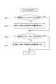
- FIG. 2 is a diagram illustrating a control flow by the water supply control unit 31 of the latent heat recovery apparatus 1 according to the embodiment of the present invention.
- 3 to 5 are diagrams showing the configuration of the heat transfer tube 2 according to one embodiment of the present invention.
- an exhaust gas E latent heat recovery device 1 (hereinafter, latent heat recovery device 1) includes a heat transfer pipe 2 and a water supply control unit 31, and a duct 4 through which the exhaust gas E flows. Installed.
- the latent heat recovery device 1 is a condensation economizer 1 and is provided in a duct 4 leading to a chimney (not shown) that discharges exhaust gas E from a boiler into the atmosphere. Then, the water supply (heated water W) is heated using the latent heat of condensation of the exhaust gas E. 1 and 6, a dry economizer (not shown) that recovers sensible heat of the exhaust gas E is provided upstream of the condensation economizer 1 in the duct 4, and the latent heat recovery device 1 and the dry economizer are provided. In combination with (not shown), improvement in the thermal efficiency of the boiler is achieved.
- the latent heat recovery apparatus 1 may be provided in the duct 4 through which the exhaust gas E generated by combustion equipment such as a diesel engine, a gas turbine, an incinerator, or a heating furnace flows.
- combustion equipment such as a diesel engine, a gas turbine, an incinerator, or a heating furnace flows.
- the heat transfer pipe 2 and the water supply control unit 31 included in the latent heat recovery apparatus 1 (condensation economizer 1) of the exhaust gas E will be described.
- the heat transfer tube 2 is installed inside a duct 4 through which the exhaust gas E circulates, and includes a water supply inlet 21h to which heated water W for collecting latent heat of the exhaust gas E is supplied, A water supply outlet 22h for discharging the heated water W is provided.
- the heat transfer pipe 2 is a pipe in which a passage (water supply passage 9) through which the heated water W flows is formed inside, and the relatively low temperature heated water W flowing through the heat transfer pipe 2 and the heat transfer pipe 2 is a heat exchanger for exchanging heat with the relatively high-temperature exhaust gas E flowing along the duct 4 outside.
- the heat transfer tube 2 has a shape that is folded back in multiple stages in a wavy shape, and the contact area with the exhaust gas E is increased (FIGS. 3 to 5). 5).
- the heat transfer tube 2 is provided with a water supply inlet 21h at one end of the heat transfer tube 2 and a water supply outlet 22h at the other end in order to allow the water to be heated W to flow inside.
- the water supply inlet 21h and the water supply outlet 22h are connected to a water supply passage 9 provided outside the duct 4, respectively.
- path 9 is supplied into the inside of the heat exchanger tube 2 from the water supply inlet 21h, passes through the inside (flow path) of the heat exchanger tube 2, and is then supplied to the external water supply channel from the water supply outlet 22h. 9 is discharged.
- the water supply inlet 21 h and the water supply outlet 22 h are connected to a header 91 (pipe header). Further, the water supply inlet 21h of the heat transfer tube 2 is located downstream of the condenser (not shown), and water from the condenser (not shown) flows into the water supply inlet 21h. On the other hand, the water supply outlet 22h is connected to a boiler (not shown). In some other embodiments, the water supply outlet 22h may be used for heat exchange with these devices by being connected to a device that uses heat, such as a water heater in a factory.
- the heat transfer tube 2 is installed inside the duct 4 through which the exhaust gas E circulates as described above.
- the duct 4 includes a descending portion 41 formed to guide the exhaust gas E from above to below, and a downstream of the descending portion 41. And a horizontal portion 42 that guides the exhaust gas E in the horizontal direction.
- the heat transfer tube 2 is installed inside the descending portion 41.
- the heat transfer tube 2 is not limited to this embodiment, and in some other embodiments, the heat transfer tube 2 includes the horizontal portion 42 in which the exhaust gas E flows in the horizontal direction, or the duct 4 that forms the upward flow of the exhaust gas. It may be installed in the part. That is, the heat transfer tube 2 can be installed without depending on the flow direction of the exhaust gas E.
- a drain that discharges the condensed water Wc (drain water) that has fallen to the outside of the duct 4 is disposed below the horizontal portion 42 that is positioned below the descending portion 41 of the duct 4.
- a discharge port 44 is provided.
- the feed water control unit 31 is a device that controls the supply of the heated water W to the feed water inlet 21h, and the feed water control unit 31 uses the outlet temperature To that is the temperature of the heated water W at the feed water outlet 22h as the set temperature Tc.
- the supply of the heated water W from the water supply inlet 21h is controlled. That is, when the outlet temperature To of the heated water W is higher than the set temperature Tc (To> Tc), the water supply control unit 31 reduces the outlet temperature To of the heated water W so as to reduce the outlet temperature To. In contrast, when the outlet temperature To of the heated water W is lower than the set temperature Tc (To ⁇ Tc), the heating water W is heated so that the outlet temperature To of the heated water W is increased. Control the supply.
- the outlet temperature To of the heated water W is controlled to be a predetermined value (set temperature Tc).
- set temperature Tc a predetermined value
- the supply of the heated water W to the feed water inlet 21 h and the flow rate of the heated water W supplied to the feed water inlet 21 h are controlled. Is done.
- the outlet temperature To can be easily maintained at the set temperature Tc by increasing or decreasing the flow rate of the heated water W supplied to the water supply inlet 21h.
- step S21 if it is detected in step S21 that the outlet temperature To of the heated water W is higher than the set temperature Tc (To> Tc), the heated water supplied to the heat transfer tube 2 in step S22. Increase the amount of water in W.
- step S23 when it is detected in step S23 that the outlet temperature To of the heated water W is lower than the set temperature Tc (To ⁇ Tc), in step S24, the amount of heated water W supplied to the heat transfer tube 2 is changed. Decrease. That is, by increasing the amount of water to be heated W when flowing into the heat transfer tube 2 through the water supply inlet 21h, the amount of water flowing through the heat transfer tube 2 can be increased, and the outlet of the water to be heated W can be increased. The temperature To can be reduced.
- the supply control of the heated water W by the water supply control unit 31 may be performed by controlling the water temperature of the heated water W. In some other embodiments, the supply control of the heated water W by the water supply control unit 31 may be performed by controlling both the flow rate of the heated water W and the water temperature.
- the water supply control unit 31 is an electronic control device 3 (computer) including a processor and a memory, as shown in FIGS. More specifically, a temperature sensor (exit temperature sensor 5) for detecting the exit temperature To is connected to the water supply control unit 31, and the exit temperature To detected by the exit temperature sensor 5 is input. Further, the water supply control unit 31 is connected to a water supply means 6 for controlling the flow rate and temperature of the heated water W supplied to the water supply inlet 21h of the heat transfer tube 2, and is configured to be able to send a control command.
- a temperature sensor exit temperature sensor 5
- the water supply control unit 31 is connected to a water supply means 6 for controlling the flow rate and temperature of the heated water W supplied to the water supply inlet 21h of the heat transfer tube 2, and is configured to be able to send a control command.
- the feed water supply means 6 includes a flow rate control means 61 (for example, an electromagnetic valve 62 capable of flow rate control) for controlling the amount of water to be heated W supplied to the feed water inlet 21 h of the heat transfer tube 2. It has become.
- the water supply control part 31 is performing water supply control as shown by FIG. 2 by comparing the exit temperature To detected by the exit temperature sensor 5, and the setting temperature Tc hold
- a flow rate control means 61 for example, an electromagnetic valve 62 capable of flow rate control
- the opening degree of the electromagnetic valve 62 is controlled so that the flow path of the heated water W is narrowed, and the target temperature passing through the feed water inlet 21h is controlled. The flow rate of the heating water W is reduced.
- the water supply control unit 31 includes a flow rate control unit 61 (for example, wax) having a temperature sensing unit that detects temperature and a valve body that is displaced according to the temperature detected by the temperature sensing unit. Valve).
- the temperature sensing unit is installed on the water supply outlet 22h side, whereby the outlet temperature To is monitored, and the valve body is installed on the water supply inlet 21h side.
- the temperature sensing part and the valve body are connected by the shaft, so that the valve body is displaced so as to widen the flow path to the water supply inlet 21h as the temperature of the water to be heated W rises.
- the valve body is displaced so as to narrow the flow path to the feed water inlet 21h as the temperature decreases.
- the set temperature Tc is arbitrary.
- the wet and dry alternating region Pr described later is set to be formed in the intermediate portion 23 of the heat transfer tube 2.
- the set temperature Tc is set to 80, for example. It may be set to ° C. In this case, the exhaust gas temperature is lowered to 58 ° C. to 62 ° C. or lower in the lower part of the heat transfer tube 2.
- the latent heat recovery apparatus 1 having such a configuration, when the exhaust gas E passes through the descending portion 41 of the duct 4, the exhaust gas E sequentially passes through each stage of the heat transfer tube 2 formed in a wavy shape. . At this time, the relatively low temperature heated water W flowing inside the heat transfer tube 2 and the relatively high temperature exhaust gas E flowing outside the heat transfer tube 2 along the duct 4 exchange heat through the heat transfer tube 2. Therefore, the temperature of the exhaust gas E decreases as the exhaust gas E passes through the heat transfer tube 2 from the upstream side to the downstream side of the duct 4. At this time, the latent heat recovery device 1 is configured so that the water vapor contained in the exhaust gas E reaches the condensation temperature (58 ° C.
- a condensation region Pc that is a region where the condensed water Wc is generated is formed in the heat transfer tube 2. Moreover, since the exhaust gas E before reaching the condensation temperature passes through the portion of the heat transfer tube 2 on the upstream side of the condensation region Pc in the flowing direction of the exhaust gas E, a dry region Pd is formed.
- the heat transfer tube 2 is formed with the drying region Pd and the condensation region Pc along the flow direction of the exhaust gas E.
- the boundary between the drying region Pd and the condensation region Pc is the temperature of the exhaust gas E or the like.
- the position varies. Specifically, when the temperature of the exhaust gas E rises, the condensation region Pc tends to move to the downstream side of the heat transfer tube 2. On the contrary, when the temperature of the exhaust gas E decreases, the condensation region Pc tends to move to the upstream side of the heat transfer tube 2.
- region Pc is fluctuate
- region Pr in which a dry state and a wet state are repeated is formed between the dry area
- a drying region Pd is formed in an upper portion of the heat transfer tube 2 (the outlet side end portion 22 in the illustration of FIGS. 1 to 8B), and the entire area below the drying region Pd is formed.
- a condensing region Pc is formed in the inlet side end portion 21 and the intermediate portion 23).
- a dry / wet alternating region Pr is formed between the condensation region Pc (wet region Pw) and the dry region Pd.
- the supply of the heated water W is controlled by the latent heat recovery apparatus 1 of the present invention so that the outlet temperature To of the heated water W is maintained at the set temperature Tc. That is, when the temperature of the exhaust gas E rises, the outlet temperature To of the heated water W rises and the condensation region Pc in the heat transfer tube 2 tends to move downstream.
- the latent heat recovery device 1 increases the degree of heat exchange so as to cancel the downstream movement of the condensation region Pc due to the rise in the temperature of the exhaust gas E, so that the temperature of the exhaust gas E becomes earlier (the duct 4 It is controlled so as to decrease to the condensation temperature on the upstream side. In other words, the condensing region Pc is controlled to move to the upstream side of the duct 4.
- the cooling power by the heat transfer tube 2 is increased, so that the downstream movement of the condensation region Pc is suppressed.
- the latent heat recovery apparatus 1 detects ambient changes such as the temperature change of the exhaust gas E at the outlet temperature To and controls the supply of the heated water W from the water supply inlet 21h so as to cancel the temperature change. Yes. Thereby, the fluctuation
- the condensing region Pc is formed in the entire lower portion of the drying region Pd (in the example of FIGS. 1 to 8B, the inlet side end portion 21 and the intermediate portion 23).
- the condensation region Pc may be formed only in the intermediate portion 23 of the heat transfer tube 2.
- the heat transfer tube 2 may be formed with a wet region Pw wetted by the movement (falling) of condensed water.
- the drying region Pd may be formed in the heat transfer tube 2 on the downstream side of the condensation region Pc.
- the condensation region Pc may be formed in the entire upper portion of the heat transfer tube 2 (in the example of FIGS. 1 to 8B, at least the portion including the outlet side end portion 22). In some cases, the dry region Pd may not be formed.
- the supply conditions of the to-be-heated water W to the inside of the heat exchanger tube 2 installed in the duct 4 are controlled based on the exit temperature To of the to-be-heated water W in the feed water exit 22h of the heat exchanger tube 2 ( Set). That is, normally, in a state where the latent heat recovery device 1 is installed in the duct 4, a region (condensation region Pc) where condensed water Wc is generated and wetted is formed in the heat transfer tube 2 of the condensation economizer 1 for latent heat recovery. .
- the dry region Pd is formed by passing the exhaust gas E before reaching the condensation temperature.
- the boundary between the dry region Pd and the condensation region Pc (wet region Pw) is between the upstream end side and the downstream end side of the heat transfer tube 2 according to the temperature of the exhaust gas E passing through the duct 4 ( Due to the fluctuation in the intermediate portion 23), a dry / wet alternating region Pr that repeats drying and wetting alternately occurs in at least a part of the heat transfer tube 2.
- the supply of the heated water W is controlled so that the outlet temperature To of the heated water W becomes a predetermined temperature (set temperature Tc), so that the drying region Pd and the condensation region Pc are controlled.
- the fluctuation of the boundary with the (wet region Pw) can be suppressed, and the range in which the dry and wet alternating region Pr in the heat transfer tube 2 is generated can be limited.
- by suppressing fluctuations in the wet and dry alternating area Pr it is possible to narrow the area where damage such as stress corrosion cracking in the heat transfer tube 2 may occur, so that maintenance such as inspection and replacement can be performed quickly and easily. It can be carried out.
- the heat transfer pipe 2 has the water supply inlet 21h located on the downstream side of the duct 4 and the water supply outlet 22h located on the upstream side of the duct 4.
- the set temperature Tc is such that the condensation temperature of the exhaust gas E is formed in a specific region of the intermediate portion 23 of the heat transfer tube 2 between the feed water inlet 21h and the feed water outlet 22h.
- the end of the heat transfer tube 2 on the side where the water supply inlet 21h is provided is the inlet side end 21, and the end of the heat transfer tube 2 on the side where the water supply outlet 22h is provided is the outlet side end 22.
- the intermediate portion 23 is a portion of the heat transfer tube 2 between the inlet side end portion 21 and the outlet side end portion 22.
- the exhaust gas E flows through the inlet side end 21 after passing through the outlet side end 22 of the heat transfer tube 2.
- the heated water W flows from the downstream side of the duct 4 toward the upstream side.
- the exhaust gas E flowing from the outlet side end portion 22 of the heat transfer tube 2 toward the inlet side end portion 21 is reliably cooled toward the downstream side inlet side end portion 21, and a part of the intermediate portion 23.
- the condensation region Pc is formed.
- the dry and wet alternating region Pr is also formed in at least a part of the intermediate portion 23.
- the heat transfer tube 2 is relatively low in the downstream side inlet side end 21 side.
- the upstream outlet side end 22 side becomes relatively hot. Since the temperature of the exhaust gas E decreases as it passes through the heat transfer tube 2, the temperature of the exhaust gas E is relatively high on the upstream side of the heat transfer tube 2 and relatively low on the downstream side of the heat transfer tube 2. For this reason, a temperature difference can be provided between the exhaust gas E and the water to be heated W over the entire inlet side end portion 21 to the outlet side end portion 22 of the heat transfer tube 2, and the heat recovery efficiency can be improved. .
- the set temperature Tc used for controlling the outlet temperature To of the heated water W is determined so that the condensation temperature is formed in an arbitrary region (specific region) of the intermediate portion 23 of the heat transfer tube 2.
- the exhaust gas E reaches the condensation temperature at any location of the heat transfer tube 2.
- the condensation region Pc tends to be formed on the upstream side with respect to the exhaust flow, and the outlet temperature To of the heated water W is set to the high temperature side. Then, the condensation region Pc tends to be formed on the downstream side.
- the condensation region Pc can be formed in a specific region of the intermediate portion 23 of the heat transfer tube 2. Further, since the dry / humid alternating region Pr is formed on the upstream end side of the exhaust gas flow in the condensation region Pc, the formation position of the dry / humid alternating region Pr can also be controlled.
- the heat exchanger tube 2 is the duct 4 so that the to-be-heated water W which flows through the inside of the heat exchanger tube 2 may flow in the direction opposite to the flow of the exhaust gas E from the downstream of the duct 4 toward the upstream. Installed inside. Thereby, the condensation temperature of water vapor contained in the exhaust gas E can be formed in the intermediate portion 23 of the heat transfer tube 2. Further, the temperature difference between the exhaust gas E and the heat transfer tube 2 that reaches the downstream end (inlet side end 21) from the upstream end (exit side end 22) of the heat transfer tube 2, It can provide over the whole and can improve heat recovery efficiency. Furthermore, by adjusting the set temperature Tc, the wet and dry alternating area Pr can be formed in an arbitrary area (specific area) of the intermediate portion 23, and maintenance can be performed quickly and easily.
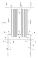
- the heat transfer tube 2 includes a straight tube portion 24 extending linearly in a direction perpendicular to the flow path formed by the duct 4, and And a curved tube portion 25 that connects ends of two or more straight tube portions 24. That is, as shown in FIGS. 3 to 5, the heat transfer tube 2 includes a straight tube portion 24 extending linearly and a curved tube portion 25 connecting the straight tube portions 24 to each other.
- the straight pipe portion 24 is a portion arranged in a direction orthogonal to the flow path of the exhaust gas E formed by the duct 4 inside the duct 4, and the plurality of straight pipe portions 24 are arranged along the duct 4. They are arranged in parallel to each other.
- the bending pipe part 25 connects the edge parts of two or more straight pipe parts 24 among the several straight pipe parts 24 arranged in parallel with each other.
- the right end of the straight pipe portion 24i closest to the water supply inlet 21h is connected to the right end of the second straight pipe portion 24 adjacent on the upstream side by the first curved pipe portion 25. Yes.
- the left end of the second straight tube portion 24 is connected to the left end of the third straight tube portion 24 on the upstream side by a second curved tube portion 25.
- the right end of the third straight tube portion 24 is connected to the fourth straight tube portion 24 adjacent on the upstream side thereof by the third curved tube portion 25, and the direction along the duct 4.
- the individual straight tube portions 24 are sequentially connected by the bent tube portions 25.
- the heat transfer tube 2 having a shape folded back in a wavy manner is formed.
- the straight pipe portion 24 i closest to the water supply inlet 21 h and the straight pipe portion 24 o closest to the water supply outlet 22 h have one end at the other straight line adjacent to the curved pipe portion 25.
- the other end is connected to the relay pipe part 26 (26i, 26o) forming the water supply inlet 21h and the water supply outlet 22h.
- the heat transfer tube 2 is a straight tube portion 24 extending linearly in a direction orthogonal to the flow path formed by the duct 4. And a curved tube portion 25 that connects ends of the two or more straight tube portions 24.
- the intermediate part 23 of the heat exchanger tube 2 is one or more curved pipe parts that connect two or more predetermined numbers of the straight pipe parts 24 and the straight pipe parts 24 arranged along the flow path formed by the duct 4.
- 25 is composed of at least one of the heat transfer tube modules 27 composed of 25
- pipe joints (union 28 in the examples of FIGS. 3 to 4) are provided at both ends of the heat transfer tube module 27, respectively.
- the heat transfer tube module 27 is connected to a portion forming another heat transfer tube 2 such as another heat transfer tube module 27 or the relay tube portion 26 by a union 28 (joint).
- the heat transfer tube 2 is configured by arranging two heat transfer tube modules 27 each having the same configuration along the duct 4 and connecting each other by a union 28 (joint). Yes. That is, each heat transfer tube module 27 is configured by combining the same number of straight tube portions 24 and the same shape of bent tube portions 25, and has the same scale.
- the intermediate section 23 may be configured by combining a plurality of heat transfer tube modules 27 of different scales.
- the first heat transfer tube module 27a located on the downstream side of the duct 4 and the second heat transfer tube module 27b located on the upstream side include two heat transfer tube modules 27.
- a relay pipe portion 26 for connecting the two Specifically, if the upstream end of the heat transfer tube module 27 is the upstream end 27u and the downstream end is the downstream end 27d, the upstream end 27u of the first heat transfer tube module 27a is:
- the straight relay pipe portion 26a is connected to one end by a union 28.
- the downstream end portion 27d of the second heat transfer tube module 27b is connected to the other end of the linear relay tube portion 26a by a union 28.
- the heat transfer tube modules 27 may be connected to each other directly by one union 28 (pipe joint).
- the downstream end portion 27d of the first heat transfer tube module 27a is connected by a union 28 to a relay tube portion 26i in which a water supply inlet 21h is formed. Further, the upstream end portion 27u of the second heat transfer tube module 27b is connected by a union 28 to the relay tube portion 26o where the water supply outlet 22h is formed.
- the heat transfer tube modules 27 and the heat transfer tube modules 27 and the relay pipe portions 26 are not connected by welding but are connected by a pipe joint such as a union 28. Therefore, it is possible to configure the heat transfer tube 2 using a plurality of heat transfer tube modules 27, and in the case where damage such as corrosion or breakage occurs in a part of the heat transfer tube 2, the heat transfer tube module 27 unit It is possible to exchange with.
- the intermediate portion 23 of the heat transfer tube 2 is formed by a part of the first heat transfer tube module 27a and a part of the second heat transfer tube module 27b.
- the damaged one of the heat transfer tube modules 27 may be replaced.
- the water supply control unit 31 if the dry and wet alternating region Pr is generated only in one of the heat transfer tube modules 27, the heat transfer tube module in which the dry and wet alternating region Pr is generated. It is also possible to carry out damage inspection and the like centering on 27.
- the shape of the relay pipe portion 26 is arbitrary, and a plurality of pipes may be connected by a union 28 or the like to form the relay pipe portion 26 (see FIGS. 3 to 4).
- the heat transfer tube module 27 and the relay tube portion 26 are described as separate members.
- the relay tube portion 26 (26a, 26i, 26o) may be a part of the heat transfer tube module, or the heat transfer tube 2 may be configured by combining the heat transfer tube modules having the same configuration. 3 to 4, the straight pipe portions 24 (specifically, the upstream end portion 27u and the downstream end portion 27d are connected directly to the relay pipe portions 26 (26a, 26i, 26o).
- the straight tube portion 24) to be formed is shorter than the length of the other straight tube portions 24 and has a curved portion, but is not limited to this embodiment.
- the length of the straight pipe portion 24 connected to each relay pipe portion 26 (26a, 26i, 26o) is the same as the length of the other straight pipe portions 24 and has a curved portion.
- each relay pipe portion 26 (26a, 26i, 26o) may be configured to have a curved portion.
- the intermediate portion is formed by the heat transfer tube module 27 connected by the pipe joint such as the union 28. 23 is configured, the damaged part can be replaced in units of the heat transfer tube module 27. For this reason, it is not necessary to replace the entire heat transfer tube 2, and the replacement cost can be reduced.
- the scale of the heat transfer tube 2 can be adjusted by the number of the heat transfer tube modules 27, the latent heat recovery apparatus 1 can be flexibly constructed according to the scale, and spare parts of the heat transfer tube module 27 can be easily secured. Can do.
- the intermediate portion 23 of the heat transfer tube 2 includes at least one straight tube portion 24, in which the straight tube portion 24, the curved tube portion 25, Are connected by a pipe joint. That is, as shown in FIG. 4, the straight tube portion 24 and the curved tube portion 25 are not connected by welding, but are connected to each other by a pipe joint.
- each heat transfer tube module 27 in each heat transfer tube module 27, the straight tube portion 24 and the curved tube portion 25 are connected by a union 28 (pipe joint). For this reason, in each heat transfer tube module 27, replacement
- the heat transfer tube 2 does not have the heat transfer tube module 27.
- a plurality of straight pipe parts 24 connected to each other by the curved pipe part 25 are arranged, so that the heat transfer pipe 2 as a whole or the intermediate between the heat transfer pipes 2 is arranged.
- Part 23 is formed.
- the intermediate portion is connected by the straight pipe portion 24 connected by the pipe joint such as the union 28. 23 is configured, the damaged part can be exchanged in units of 24 straight tube portions. For this reason, it is not necessary to replace the entire heat transfer tube 2, and the replacement cost can be reduced. Furthermore, since the scale of the heat transfer tubes 2 can be adjusted by the number of straight tube portions 24, the latent heat recovery apparatus 1 can be flexibly constructed according to the scale, and spare parts for the straight tube portions 24 can be easily secured. be able to.
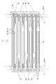
- the heat transfer tube 2 includes a straight tube portion 24 extending linearly in a direction orthogonal to the flow path formed by the duct 4.
- a curved tube portion 25 that connects the ends of two or more straight tube portions 24 to each other.
- the latent heat recovery apparatus 1 further includes a tube plate 7 that fixes the end of the straight tube portion 24 at each end of the straight tube portion 24.
- the intermediate portion 23 includes at least one straight tube portion 24.
- the tube plate 7 is a plate-like member.
- the tube plate 7 has a through-hole which penetrates this plate-shaped member, and the straight tube part 24 of the heat exchanger tube 2 is passed by passing a linear tube (straight tube) through each through-hole. Is formed.
- the heat transfer tube 2 is configured by installing a plurality of straight tubes (straight tube portions 24) between two tube plates 7. More specifically, each tube sheet 7 is provided with a plurality of through holes along the vertical direction (the direction in which the exhaust gas E flows) and the horizontal direction. 28 through holes arranged in the vertical direction are provided in three rows in the horizontal direction. And each tube sheet 7 is arrange
- the through holes of the tube plates 7 also face each other, and both ends of the straight tube (straight tube portion 24) are fixed to each of the facing through holes.
- the bending tube part 25 is installed in the outer side of each tube sheet 7, and connects the 2 or more several straight tube part 24 collectively.
- the heat transfer tube 2 is configured to form a flow of the heated water W in a specific direction (from the left end to the right end or from the right end to the left end) for each of the plurality of straight tube portions 24.
- the heated water W supplied from the water supply inlet 21h is described as four straight tubes when focusing on the foremost straight tube portion 24 arranged in the longitudinal direction of the tube plate 7.
- the bent tube portion 25 at the left end also connects the eight straight tube portions 24, and the heated water W flowing in from the four straight tube portions 24 among the four straight tube portions 24 is left in the remaining four disposed on the upstream side of the duct 4. It is configured to repeat the flow to the straight pipe portion 24 (third stage) up to the water supply outlet 22h.
- each straight tube portion 24 is fixed by the tube plate 7 and forms a flow path of the heated water W together with the curved tube portion 25.
- the straight tube portion 24 and the tube plate 7 are not connected by welding but are inserted into the through holes of the tube plate 7 and installed.
- the curved tube portion 25 and the tube plate 7 are not connected by welding, but the curved tube portion 25 and the tube plate 7 are set to be separable (removable).
- the scale of the heat transfer tube 2 can be adjusted by the scale of the tube plate 7 such as the number of through holes, and if damage such as corrosion or breakage occurs in a part of the heat transfer tube 2, the straight tube portion It can be exchanged in 24 units.
- the curved tube portion 25 that connects the straight tube portion 24 to be replaced is removed, and the straight tube portion 24 to be replaced is removed by pulling it out from the through hole. And after inserting the straight pipe part 24 used as a replacement into the through-hole from which this straight pipe part 24 was removed, the operation
- the intermediate portion 23 is configured by the straight tube portion 24 connected by the tube plate 7. Therefore, the damaged part can be exchanged in units of the straight tube portion 24. For this reason, it is not necessary to replace the entire heat transfer tube 2, and the replacement cost can be reduced. Furthermore, since the scale of the heat transfer tube 2 can be adjusted according to the scale of the tube plate 7, the latent heat recovery apparatus 1 can be flexibly constructed according to the scale and a spare part of the straight tube portion 24 can be easily secured. Can do.
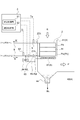
- the latent heat recovery apparatus 1 further includes a heating unit 8 that preheats the water to be heated W, and the water supply control unit 31 has a temperature of the water to be heated W. Is below the predetermined temperature, the heated water W preheated by the heating means 8 is supplied to the feed water inlet 21h.
- the heating means 8 is a preheating tube 81.
- the preheating pipe 81 is installed in the duct 4 downstream of the heat transfer pipe 2. Further, both ends of the preheating pipe 81 communicate with the water supply passage 9 and the water supply inlet 21h, respectively, and the heated water W can reach the water supply inlet 21h of the heat transfer pipe 2 via the preheating pipe 81. It constitutes a preheating route Rh.
- a preheating route Rh and a direct route Rd that leads directly to the water supply inlet 21h without passing through the preheating route Rh are provided as paths through which the heated water W reaches the water supply inlet 21h of the heat transfer tube 2.
- a flow path switching means 63 water supply means 6) for switching between the direct route Rd and the preheating route Rh is provided in the water supply passage 9.
- the flow path switching means 63 is provided between the header 91 and the water supply inlet 21h. Then, by controlling the flow path switching unit 63, the heated water W that has passed through at least one of the direct route Rd and the preheating route Rh is supplied to the water supply inlet 21h.
- the flow path switching means 63 may be a three-way valve connected to the water supply passage 9, the direct route, and the preheating route.
- the flow path switching means 63 may be constituted by a plurality of valves, and a valve is installed at each of the inlet or outlet of the direct route Rd and the preheating route Rh, and the opening degree of each valve is adjusted, respectively. You may comprise so that the route
- the latent heat recovery apparatus 1 including the heating unit 8 includes a flow path switching unit 32 that switches between the direct route Rd and the preheat route Rh as illustrated in FIG.
- the flow path switching unit 32 includes an electronic control device (computer) having a processor and a memory.
- the flow path switching unit 32 is connected to an inlet temperature sensor 52 capable of detecting the temperature of the heated water W (inlet temperature Ti) at the feed water inlet 21 h of the heat transfer tube 2 and the flow path switching means 63.
- the flow path switching means 63 is two electromagnetic valves (electromagnetic valve 62 and electromagnetic valve 64), and the opening degree of the electromagnetic valve 62 and the electromagnetic valve 64 is controlled according to a command from the flow path switching unit 32. Is done.
- the flow path switching unit 32 passes the heated water W through the preheating route Rh passing through the preheating pipe 81.
- the solenoid valve 64 is opened.
- the solenoid valve 62 may be completely closed so that the heated water W does not flow to the direct route Rd.
- the preheated water W to be heated is supplied from the water supply inlet 21h.
- the electromagnetic valve 64 is closed so that the heated water W does not pass through the preheating route Rh.
- the heated water W that has not been preheated is supplied to the heat transfer tube 2 from the water supply inlet 21h.
- the predetermined temperature depends on the rising temperature (condensation temperature) of the target heated water W, the position of the condensation region Pc in the target heat transfer tube 2 (the position of the specific region), the heat transfer area of the heat transfer tube 2, and the like.
- the temperature may be any temperature in the range of 10 degrees (° C.) to 30 degrees (° C.).
- the outlet of the heated water W of the preheating pipe 81 may be connected to the water supply passage 9 outside the duct 4, for example, may be connected between the electromagnetic valve 62 and the electromagnetic valve 64.
- the electromagnetic valve 64 that controls the inflow of the water to be heated W to the preheating route Rh may be inside the duct 4, for example, between the preheating pipe 81 and the heat transfer pipe 2.
- the temperature of the exhaust gas E when passing through the preheating pipe 81 along the duct 4 is still higher than the temperature of the heated water W before being heated by the heating means 8. For this reason, it becomes possible to preheat (heat) the to-be-heated water W before supplying to the heat exchanger tube 2 from the feed water inlet 21h by exchanging heat with the to-be-heated water W which passes the preheating pipe 81, and waste gas E. It has become. For this reason, when the temperature of the heated water W is equal to or lower than the predetermined temperature, the heated water W is preheated and then supplied to the heat transfer tube 2, thereby preventing a large change in the position of the condensation region Pc in the heat transfer tube 2. be able to. In particular, even when the temperature of the heated water W supplied from the water supply inlet 21h changes depending on the season, it is possible to prevent fluctuations in the condensation region Pc formed in the heat transfer tube 2.
- the heated water W when the temperature of the heated water W to be supplied from the feed water inlet 21h is equal to or lower than a predetermined temperature, the heated water W is preheated.
- region Pw) which arise in the heat exchanger tube 2 can be suppressed, and the range which the dry-humidity alternating area
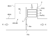
- the duct 4 forms a first duct 45 that forms the bypassed passage Rm and a bypass passage Rb that bypasses the bypassed passage Rm.
- the latent heat recovery apparatus 1 further includes a damper 47 that switches between the bypass passage Rm and the bypass passage Rb, and the heat transfer tube 2 is installed in the bypass passage Rb.
- the first duct 45 is formed to extend linearly in the horizontal direction. Further, an opening 45h (the upper surface of the first duct 45 in the illustration of FIG. 7) is provided in a part of the first duct 45.
- the second duct 46 has a box shape, and one surface thereof is open (opening 46h).
- the first duct 45 and the second duct 46 are connected by the opening 45 h of the first duct 45 and the opening 46 h of the second duct 46.
- a space by the inside of the second duct 46 is formed above the linear first duct 45.
- a plate-like damper 47 partially partitions the internal space of the second duct 46.
- the second duct 46 forms a bypass passage Rb that allows the ducts 4 on both sides of this part to communicate with each other without passing through a part of the passage formed by the first duct 45 (the bypassed passage Rm). ing.
- bypass passage Rb is formed by a left passage formed by the second duct 46 and the left surface of the damper 47 and a right passage formed by the second duct 46 and the right surface of the damper 47.
- the damper 47 is installed so that it can be switched between the bypassed passage Rm and the bypass passage Rb.
- the center of the plate-like damper 47 is located at the boundary between the first duct 45 and the second duct 46, and the center of the damper 47 is the center of rotation.
- the damper 47 is configured to be rotatable.
- the exhaust gas E flows through the bypass passage Rb.
- the exhaust gas E flowing into the second duct 46 from the first duct 45 rises in the left passage of the bypass passage Rb, then descends in the right passage, and flows downstream of the damper 47 of the first duct 45.
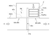
- the damper 47 may be composed of a plurality of dampers.
- two dampers, a first damper 47a and a second damper 47b are provided. It may be constituted by. That is, the first damper 47a is for permitting or prohibiting the exhaust gas E from passing further downstream of the duct 4 through a part of the first duct 45 (the bypassed passage Rm). It is installed so that the exhaust gas E does not pass through at least a part of the passage Rm.
- the second damper 47b is for permitting or prohibiting the exhaust gas E from passing through the second duct 46 (bypass passage Rb) and downstream of the bypassed passage Rm.
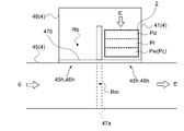
- FIGS. 8A to 8B two openings 45h are provided in different parts of the first duct 45, and the second duct 46 is provided in each of the two openings 45h of the first duct 45. Openings 46h (inlet and outlet) at both ends are connected to each other.
- the second damper 47b is configured to be able to cover both the inlet and the outlet of the second duct 46 at the same time.
- FIG. 8A when the bypass D Rm is blocked by the first damper 47a and both ends of the second duct 46 are not blocked by the second damper 47b, the exhaust gas E passes through the bypass Rb. Will flow.
- FIG. 8A when the bypass D Rm is blocked by the first damper 47a and both ends of the second duct 46 are not blocked by the second damper 47b, the exhaust gas E passes through the bypass Rb. Will flow.
- FIG. 8A when the bypass D Rm is blocked by the first damper 47a and both ends of the second duct 46 are not blocked by the second damper 47b, the
- the second duct 46 may be installed inside the second duct 46 other than both ends, and may be provided in at least one of the upstream side or the downstream side where the heat transfer tube 2 is installed in the second duct 46 (bypass passage Rb). .
- the first damper 47a and the second damper 47b are rotated around their respective centers and ends, or at least partly moved to the outside of the duct 4 so that the passage is opened. It may be closed.
- the damper 47 opens the bypass passage Rb and closes the bypassed passage Rm during operation. For this reason, since the exhaust gas E passes through the bypass passage Rb without passing through the bypassed passage Rm, the latent heat of the exhaust gas E is recovered by the latent heat recovery device 1. During maintenance, the damper 47 closes the bypass passage Rb and opens the bypassed passage Rm. For this reason, since the exhaust gas E passes through the bypassed passage Rm without passing through the bypass passage Rb, the exhaust gas E does not pass through the latent heat recovery device 1. For this reason, it becomes possible to perform the maintenance of the latent heat recovery apparatus 1 even during operation of operating a combustion apparatus such as a boiler.
- the exhaust gas E flowing through the duct 4 can pass through either the bypass passage Rm formed in the first duct 45 or the bypass passage Rb formed in the second duct 46 by the damper 47. It is configured. For this reason, at the time of maintenance such as inspection or replacement of the heat transfer tube 2, by switching the passage so that the exhaust gas E passes through the bypassed passage Rm, maintenance work can be performed without stopping combustion equipment such as a boiler. .
- the water supply inlet 21h and the water supply outlet 22h are connected to the header 91, and at least one of the water supply inlet 21h and the header 91 or at least one of the water supply outlet 22h and the header 91 is Are connected by a flexible tube 92.
- the header 91 is a header, and steam generated by a combustion device such as a boiler is sent to the header 91 and is distributed from the header 91 to the heat transfer tube 2 (latent heat recovery device 1).
- the to-be-heated water W from the heat exchanger tube 2 is also sent to the header 91, and is sent to combustion apparatuses, such as a boiler, and apparatuses, such as a water heater.
- the flexible tube 92 is a flexible tube and is formed of metal, rubber, or the like.
- the header 91 and the heat transfer tube 2 are connected by the flexible tube 92. In this way, by using the flexible tube 92, the connection with the header 91 can be easily constructed, and the emergency plug construction (stopping) can be easily performed.
- the present invention is not limited to the above-described embodiments, and includes forms obtained by modifying the above-described embodiments and forms obtained by appropriately combining these forms.
- Latent heat recovery device (condensation economizer) 2 Heat transfer pipe 21 Inlet side end 21h Water supply inlet 22 Outlet side end 22h Water supply outlet 23 Intermediate part 24 Straight pipe part 24i Straight pipe part 24o closest to the water supply inlet 25 Straight pipe part 25 closest to the water supply outlet Curved pipe part 26 Relay Pipe part 26a Straight relay pipe part 26i Relay pipe part 26o where a water supply inlet is formed Relay pipe part 27 where a water supply outlet is formed 27 Heat transfer pipe module 27a First heat transfer pipe module 27b Second heat transfer pipe module 27u Upstream end 27b Downstream end 28 Union 3 Electronic control unit 31 Water supply control unit 32 Channel switching unit 4 Duct 41 Lowering unit 42 Horizontal unit 44 Drain discharge port 45 First duct (circumferential path) 45h First duct opening 46 Second duct (bypass passage) 46h Opening of second duct 47 Damper 5 Outlet temperature sensor 52 Inlet temperature sensor 6 Water supply means 61 Flow rate control means 62 Electromagnetic valve 63 Flow path switching means 64 Electromagnetic valve 7
Landscapes
- Engineering & Computer Science (AREA)
- Physics & Mathematics (AREA)
- Thermal Sciences (AREA)
- Mechanical Engineering (AREA)
- General Engineering & Computer Science (AREA)
- Chemical & Material Sciences (AREA)
- Combustion & Propulsion (AREA)
- Heat-Exchange Devices With Radiators And Conduit Assemblies (AREA)
- Instantaneous Water Boilers, Portable Hot-Water Supply Apparatuses, And Control Of Portable Hot-Water Supply Apparatuses (AREA)
Priority Applications (2)
| Application Number | Priority Date | Filing Date | Title |
|---|---|---|---|
| US15/576,498 US10514183B2 (en) | 2015-07-29 | 2016-07-15 | Exhaust gas latent heat recovery device |
| MX2017014976A MX2017014976A (es) | 2015-07-29 | 2016-07-15 | Dispositivo de recuperacion de calor latente de gas de exhaustacion. |
Applications Claiming Priority (2)
| Application Number | Priority Date | Filing Date | Title |
|---|---|---|---|
| JP2015149701A JP6552904B2 (ja) | 2015-07-29 | 2015-07-29 | 排ガスの潜熱回収装置 |
| JP2015-149701 | 2015-07-29 |
Publications (1)
| Publication Number | Publication Date |
|---|---|
| WO2017018253A1 true WO2017018253A1 (ja) | 2017-02-02 |
Family
ID=57885531
Family Applications (1)
| Application Number | Title | Priority Date | Filing Date |
|---|---|---|---|
| PCT/JP2016/071032 Ceased WO2017018253A1 (ja) | 2015-07-29 | 2016-07-15 | 排ガスの潜熱回収装置 |
Country Status (4)
| Country | Link |
|---|---|
| US (1) | US10514183B2 (enExample) |
| JP (1) | JP6552904B2 (enExample) |
| MX (1) | MX2017014976A (enExample) |
| WO (1) | WO2017018253A1 (enExample) |
Cited By (1)
| Publication number | Priority date | Publication date | Assignee | Title |
|---|---|---|---|---|
| CN108317868A (zh) * | 2018-02-07 | 2018-07-24 | 新昌县海格赛斯贸易有限公司 | 一种蒸汽余热回收结构 |
Families Citing this family (1)
| Publication number | Priority date | Publication date | Assignee | Title |
|---|---|---|---|---|
| JP7311990B2 (ja) * | 2019-03-22 | 2023-07-20 | 荏原環境プラント株式会社 | 排熱回収ボイラ及び排熱回収ボイラの伝熱管の温度の制御方法 |
Citations (4)
| Publication number | Priority date | Publication date | Assignee | Title |
|---|---|---|---|---|
| WO2011111450A1 (ja) * | 2010-03-12 | 2011-09-15 | 株式会社日立製作所 | 石炭火力発電プラント及び石炭火力発電プラントの運転方法 |
| JP2012007818A (ja) * | 2010-06-25 | 2012-01-12 | Mitsubishi Heavy Ind Ltd | 排ガスの余熱回収装置 |
| JP2012057860A (ja) * | 2010-09-09 | 2012-03-22 | Mitsubishi Heavy Ind Ltd | 排熱回収装置 |
| JP2014206374A (ja) * | 2014-07-04 | 2014-10-30 | 三浦工業株式会社 | エコノマイザ制御装置、エコノマイザ及びボイラ |
Family Cites Families (11)
| Publication number | Priority date | Publication date | Assignee | Title |
|---|---|---|---|---|
| US4073267A (en) * | 1975-10-03 | 1978-02-14 | General Atomic Company | Vapor generator |
| US4173949A (en) * | 1978-01-23 | 1979-11-13 | Tranter, Inc. | Feedwater preheat corrosion control system |
| US4776391A (en) * | 1979-10-04 | 1988-10-11 | Heat Exchanger Industries, Inc. | Heat exchanger method and apparatus |
| CA2102637A1 (en) * | 1992-11-13 | 1994-05-14 | David H. Dietz | Circulating fluidized bed reactor combined cycle power generation system |
| US5567215A (en) * | 1994-09-12 | 1996-10-22 | The Babcock & Wilcox Company | Enhanced heat exchanger flue gas treatment using steam injection |
| US6748880B2 (en) * | 2000-12-20 | 2004-06-15 | The Babcock & Wilcox Company | Boiler internal flue gas by-pass damper for flue gas temperature control |
| EP2335806A1 (en) * | 2009-12-04 | 2011-06-22 | Alstom Technology Ltd | Method and system for condensing water vapour from a carbon dioxide rich flue gas |
| JP5812768B2 (ja) * | 2011-08-31 | 2015-11-17 | 三菱日立パワーシステムズ株式会社 | 脱硝触媒の再生方法及び重質油焚き燃焼装置の運転方法 |
| JP5986821B2 (ja) * | 2012-06-18 | 2016-09-06 | 株式会社岡村製作所 | ショーケース |
| JP6147601B2 (ja) * | 2013-07-24 | 2017-06-14 | 三菱日立パワーシステムズ株式会社 | 排ガス潜熱回収装置 |
| JP2014169693A (ja) | 2013-10-29 | 2014-09-18 | Ecosupport Inc | ガスタービン・コンバインドサイクル発電システム |
-
2015
- 2015-07-29 JP JP2015149701A patent/JP6552904B2/ja not_active Expired - Fee Related
-
2016
- 2016-07-15 US US15/576,498 patent/US10514183B2/en not_active Expired - Fee Related
- 2016-07-15 WO PCT/JP2016/071032 patent/WO2017018253A1/ja not_active Ceased
- 2016-07-15 MX MX2017014976A patent/MX2017014976A/es unknown
Patent Citations (4)
| Publication number | Priority date | Publication date | Assignee | Title |
|---|---|---|---|---|
| WO2011111450A1 (ja) * | 2010-03-12 | 2011-09-15 | 株式会社日立製作所 | 石炭火力発電プラント及び石炭火力発電プラントの運転方法 |
| JP2012007818A (ja) * | 2010-06-25 | 2012-01-12 | Mitsubishi Heavy Ind Ltd | 排ガスの余熱回収装置 |
| JP2012057860A (ja) * | 2010-09-09 | 2012-03-22 | Mitsubishi Heavy Ind Ltd | 排熱回収装置 |
| JP2014206374A (ja) * | 2014-07-04 | 2014-10-30 | 三浦工業株式会社 | エコノマイザ制御装置、エコノマイザ及びボイラ |
Cited By (1)
| Publication number | Priority date | Publication date | Assignee | Title |
|---|---|---|---|---|
| CN108317868A (zh) * | 2018-02-07 | 2018-07-24 | 新昌县海格赛斯贸易有限公司 | 一种蒸汽余热回收结构 |
Also Published As
| Publication number | Publication date |
|---|---|
| MX2017014976A (es) | 2018-03-23 |
| JP2017032166A (ja) | 2017-02-09 |
| US10514183B2 (en) | 2019-12-24 |
| JP6552904B2 (ja) | 2019-07-31 |
| US20180149388A1 (en) | 2018-05-31 |
Similar Documents
| Publication | Publication Date | Title |
|---|---|---|
| CN101074771B (zh) | 一种用于选择性催化反应器温度控制的多通道省煤器和方法 | |
| KR101364944B1 (ko) | 배기 가스의 여열 회수 장치 | |
| CN103328887B (zh) | 用于控制锅炉内蒸汽温度的方法和装置 | |
| US11828461B2 (en) | Corrosion resistant air preheater with lined tubes | |
| DK2442061T3 (en) | Process for cooling a combustion plant's flue gases in a heat exchanger in a steam generating plant | |
| CN107208888B (zh) | 热交换器以及热交换器的控制方法 | |
| CN103711532B (zh) | 具有蒸汽涡轮机抽汽控制的蒸汽发电设备 | |
| JP6552904B2 (ja) | 排ガスの潜熱回収装置 | |
| JP5790973B2 (ja) | 温水装置 | |
| JP2023533908A (ja) | リアルタイムの腐食監視に基づく熱交換器制御のシステムおよび方法 | |
| JP2012057860A (ja) | 排熱回収装置 | |
| Mehta | Waste heat recovery | |
| KR101750892B1 (ko) | 고로 가스 예열 장치 | |
| JP2006153375A (ja) | 熱交換装置および燃焼装置 | |
| KR101508755B1 (ko) | 모노드럼형 배열회수 증기발생기 | |
| KR200234751Y1 (ko) | 배열회수시스템용순환수장치 | |
| KR102428395B1 (ko) | 배기열 회수효율을 높이기 위한 보일러 | |
| JP2016005830A (ja) | 排煙処理装置と該排煙処理装置の運転方法 | |
| KR101767766B1 (ko) | 가열로의 배열 회수장치 | |
| KR102435061B1 (ko) | 복합열교환기를 통해 배기열 회수효율을 높이기 위한 보일러 | |
| JP2025094963A (ja) | ボイラからの排ガスの温度制御方法 | |
| CN106016326A (zh) | 一种烟气超低排放燃煤发电机组管式ggh系统的烟气余热回收装置及方法 | |
| CN106133468A (zh) | 尤其用于燃油加热器的板式换热器 | |
| KR20190076566A (ko) | 배가스 현열 회수 장치 | |
| PL213415B1 (pl) | Rusztowy kocioł parowy lub wodny |
Legal Events
| Date | Code | Title | Description |
|---|---|---|---|
| 121 | Ep: the epo has been informed by wipo that ep was designated in this application |
Ref document number: 16830358 Country of ref document: EP Kind code of ref document: A1 |
|
| WWE | Wipo information: entry into national phase |
Ref document number: MX/A/2017/014976 Country of ref document: MX Ref document number: 15576498 Country of ref document: US |
|
| NENP | Non-entry into the national phase |
Ref country code: DE |
|
| 122 | Ep: pct application non-entry in european phase |
Ref document number: 16830358 Country of ref document: EP Kind code of ref document: A1 |