WO2017018139A1 - Dispositif pour opération chirurgicale destiné à un endoscope, et dispositif de guidage - Google Patents
Dispositif pour opération chirurgicale destiné à un endoscope, et dispositif de guidage Download PDFInfo
- Publication number
- WO2017018139A1 WO2017018139A1 PCT/JP2016/069922 JP2016069922W WO2017018139A1 WO 2017018139 A1 WO2017018139 A1 WO 2017018139A1 JP 2016069922 W JP2016069922 W JP 2016069922W WO 2017018139 A1 WO2017018139 A1 WO 2017018139A1
- Authority
- WO
- WIPO (PCT)
- Prior art keywords
- holding
- outer tube
- insertion portion
- holding part
- fixing
- Prior art date
Links
Images


Classifications
-
- A—HUMAN NECESSITIES
- A61—MEDICAL OR VETERINARY SCIENCE; HYGIENE
- A61B—DIAGNOSIS; SURGERY; IDENTIFICATION
- A61B1/00—Instruments for performing medical examinations of the interior of cavities or tubes of the body by visual or photographical inspection, e.g. endoscopes; Illuminating arrangements therefor
- A61B1/00147—Holding or positioning arrangements
- A61B1/00154—Holding or positioning arrangements using guiding arrangements for insertion
-
- A—HUMAN NECESSITIES
- A61—MEDICAL OR VETERINARY SCIENCE; HYGIENE
- A61B—DIAGNOSIS; SURGERY; IDENTIFICATION
- A61B1/00—Instruments for performing medical examinations of the interior of cavities or tubes of the body by visual or photographical inspection, e.g. endoscopes; Illuminating arrangements therefor
- A61B1/00064—Constructional details of the endoscope body
- A61B1/00071—Insertion part of the endoscope body
- A61B1/0008—Insertion part of the endoscope body characterised by distal tip features
- A61B1/00087—Tools
-
- A—HUMAN NECESSITIES
- A61—MEDICAL OR VETERINARY SCIENCE; HYGIENE
- A61B—DIAGNOSIS; SURGERY; IDENTIFICATION
- A61B1/00—Instruments for performing medical examinations of the interior of cavities or tubes of the body by visual or photographical inspection, e.g. endoscopes; Illuminating arrangements therefor
- A61B1/00112—Connection or coupling means
- A61B1/00121—Connectors, fasteners and adapters, e.g. on the endoscope handle
- A61B1/00128—Connectors, fasteners and adapters, e.g. on the endoscope handle mechanical, e.g. for tubes or pipes
-
- A—HUMAN NECESSITIES
- A61—MEDICAL OR VETERINARY SCIENCE; HYGIENE
- A61B—DIAGNOSIS; SURGERY; IDENTIFICATION
- A61B1/00—Instruments for performing medical examinations of the interior of cavities or tubes of the body by visual or photographical inspection, e.g. endoscopes; Illuminating arrangements therefor
- A61B1/00131—Accessories for endoscopes
- A61B1/00135—Oversleeves mounted on the endoscope prior to insertion
-
- A—HUMAN NECESSITIES
- A61—MEDICAL OR VETERINARY SCIENCE; HYGIENE
- A61B—DIAGNOSIS; SURGERY; IDENTIFICATION
- A61B1/00—Instruments for performing medical examinations of the interior of cavities or tubes of the body by visual or photographical inspection, e.g. endoscopes; Illuminating arrangements therefor
- A61B1/06—Instruments for performing medical examinations of the interior of cavities or tubes of the body by visual or photographical inspection, e.g. endoscopes; Illuminating arrangements therefor with illuminating arrangements
-
- A—HUMAN NECESSITIES
- A61—MEDICAL OR VETERINARY SCIENCE; HYGIENE
- A61B—DIAGNOSIS; SURGERY; IDENTIFICATION
- A61B1/00—Instruments for performing medical examinations of the interior of cavities or tubes of the body by visual or photographical inspection, e.g. endoscopes; Illuminating arrangements therefor
- A61B1/04—Instruments for performing medical examinations of the interior of cavities or tubes of the body by visual or photographical inspection, e.g. endoscopes; Illuminating arrangements therefor combined with photographic or television appliances
- A61B1/05—Instruments for performing medical examinations of the interior of cavities or tubes of the body by visual or photographical inspection, e.g. endoscopes; Illuminating arrangements therefor combined with photographic or television appliances characterised by the image sensor, e.g. camera, being in the distal end portion
-
- A—HUMAN NECESSITIES
- A61—MEDICAL OR VETERINARY SCIENCE; HYGIENE
- A61B—DIAGNOSIS; SURGERY; IDENTIFICATION
- A61B1/00—Instruments for performing medical examinations of the interior of cavities or tubes of the body by visual or photographical inspection, e.g. endoscopes; Illuminating arrangements therefor
- A61B1/06—Instruments for performing medical examinations of the interior of cavities or tubes of the body by visual or photographical inspection, e.g. endoscopes; Illuminating arrangements therefor with illuminating arrangements
- A61B1/0661—Endoscope light sources
- A61B1/0669—Endoscope light sources at proximal end of an endoscope
-
- A—HUMAN NECESSITIES
- A61—MEDICAL OR VETERINARY SCIENCE; HYGIENE
- A61B—DIAGNOSIS; SURGERY; IDENTIFICATION
- A61B1/00—Instruments for performing medical examinations of the interior of cavities or tubes of the body by visual or photographical inspection, e.g. endoscopes; Illuminating arrangements therefor
- A61B1/313—Instruments for performing medical examinations of the interior of cavities or tubes of the body by visual or photographical inspection, e.g. endoscopes; Illuminating arrangements therefor for introducing through surgical openings, e.g. laparoscopes
- A61B1/3132—Instruments for performing medical examinations of the interior of cavities or tubes of the body by visual or photographical inspection, e.g. endoscopes; Illuminating arrangements therefor for introducing through surgical openings, e.g. laparoscopes for laparoscopy
Definitions
- the present invention relates to an endoscopic surgical apparatus and a guide apparatus, and more particularly to an endoscopic surgical apparatus and a guide apparatus that link an endoscope and a treatment tool.
- a laparoscope is known as an endoscopic instrument that is inserted into the abdominal cavity from the body surface skin. Surgery using this laparoscope (laparoscopic surgery) is widely used in many surgeries in recent years because the surgical wound is smaller than open surgery or thoracotomy, and the postoperative period of bed rest can be shortened. .
- the applicant of the present application has proposed a technique for interlocking the endoscope and the treatment instrument in a state where the endoscope and the treatment instrument are inserted into the outer tube (for example, see Patent Document 1).
- the endoscope moves forward and backward with play with respect to the advancement / retraction movement of the treatment tool, so that the size of the observation target is prevented from changing when the treatment tool is slightly displaced in the axial direction. It is possible to maintain a proper perspective and to provide a stable observation image.
- the range of the observation image obtained by the endoscope is changed in conjunction with the treatment tool, so that the size of the observation object changes according to the operation of the treatment tool. This makes it possible to easily obtain an image desired by the surgeon and improve operability.
- the cost reduction and the simplification of the configuration are major issues in the outer tube, and in particular, the cost can be reduced and the configuration can be simplified after satisfying the function of interlocking the endoscope and the treatment instrument. It is desired.
- the present invention has been made in view of such circumstances, and is intended for an endoscope that can reduce the cost and simplify the configuration while satisfying the function of interlocking two medical instruments in the outer tube. It is an object of the present invention to provide a surgical operation apparatus and a guide apparatus.
- an endoscopic surgical apparatus includes a first medical instrument having a first insertion portion, a second medical instrument having a second insertion portion, The first insertion portion and the second insertion portion are inserted, the cylindrical outer tube that guides the first insertion portion and the second insertion portion into the body cavity, the inner tube, and the inner tube are inserted into the outer tube.
- a minimally invasive operation (with less burden on the body) can be performed. It can be carried out.
- first medical instrument held in the first holding part and the second medical instrument held in the second holding part can be moved in the axial direction independently when the connecting member is in a relaxed state, When the connecting member is in a tensile state, the connecting member can be moved in conjunction. Therefore, the first medical instrument and the second medical instrument can be operated in conjunction with each other with “play”.
- the first medical instrument is an endoscope
- the field of view (imaging area) of the endoscope can be made to follow the treatment portion of the second medical instrument, and an image that is always optimal for the treatment can be displayed to the operator. (The image desired by the surgeon can be displayed without stress).
- the endoscope since the endoscope is not displaced with respect to the minute displacement in the axial direction of the second medical instrument, it is possible to prevent the screen of the image captured by the endoscope from being shaken and to provide an image that is easy for the operator to view. Can do.
- maintenance part connects the 1st holding
- the 1st medical instrument which has a 1st insertion part, and the 2nd medical instrument which has a 2nd insertion part A tubular outer tube through which the first insertion portion and the second insertion portion are inserted to guide the first insertion portion and the second insertion portion into the body cavity, and an inner portion of the outer tube, A first holding portion for holding the first insertion portion inserted through the first holding portion, which moves in the axial direction of the outer tube while holding the first insertion portion, and is disposed inside the outer tube, A second holding portion for holding a second insertion portion inserted into the outer tube, the second holding portion moving in the axial direction of the outer tube while holding the first insertion portion; and a first holding portion A connecting member having a first fixing part fixed to the second holding part and a second fixing part fixed to the second holding part, wherein the first fixing part and the second fixing part A slack portion between the first fixing
- two medical instruments can be inserted into the body cavity via one mantle tube, and only one puncture site on the body wall is required, so that a minimally invasive operation can be performed.
- first medical instrument held by the first holding part and the second medical instrument held by the second holding part move independently in the axial direction when the slack part of the connecting member is loose. And can be moved in conjunction with each other when the slack portion is extended. Therefore, the first medical instrument and the second medical instrument can be operated in conjunction with each other with “play”.
- extension includes the meaning that what has been bent becomes straight.
- the first medical instrument is an endoscope
- the field of view (imaging area) of the endoscope can be made to follow the treatment portion of the second medical instrument, and an image that is always optimal for the treatment can be displayed to the operator. (The image desired by the surgeon can be displayed without stress).
- the endoscope since the endoscope is not displaced with respect to the minute displacement in the axial direction of the second medical instrument, it is possible to prevent the screen of the image captured by the endoscope from being shaken and to provide an image that is easy for the operator to view. Can do.
- maintenance part is a simple thing which connects a 1st holding
- the connecting member may be a flexible member.
- the flexible member may be a string-like or belt-like member.
- the first medical instrument is an endoscope in which an observation part is provided at the tip of the first insertion part
- the second medical instrument is a first medical instrument. It can be set as the aspect which is a treatment tool with which the treatment part was provided in the front-end
- an endoscopic surgical apparatus includes a first medical instrument having a first insertion part, and a second medical instrument having a second insertion part.
- a connecting member having a first fixing part fixed to the second holding part and a second fixing part fixed to the second holding part, wherein the first fixing part to the second fixing part Length at will and a short connecting member than the axial length of the long and the outer tube than the
- two medical instruments can be inserted into the body cavity via one mantle tube, and only one puncture site on the body wall is required, so that a minimally invasive operation can be performed.
- first medical instrument held by the first holding unit and the second medical instrument held by the second holding unit can be operated in an interlocking manner by having “play” by the connecting member.
- the first medical instrument is an endoscope
- the field of view (imaging area) of the endoscope can be made to follow the treatment portion of the second medical instrument, and an image that is always optimal for the treatment can be displayed to the operator. (The image desired by the surgeon can be displayed without stress).
- the endoscope since the endoscope is not displaced with respect to the minute displacement in the axial direction of the second medical instrument, it is possible to prevent the screen of the image captured by the endoscope from being shaken and to provide an image that is easy for the operator to view. Can do.
- maintenance part is a simple thing which connects a 1st holding
- the 1st insertion part of the 1st medical instrument and the 2nd insertion part of the 2nd medical instrument are penetrated, and the guidance apparatus which concerns on the other aspect of this invention is 1st insertion part.
- a second holding portion that moves in the axial direction of the outer tube while holding the first insertion portion, a first fixing portion that is fixed to the first holding portion, and a second fixing portion that is fixed to the second holding portion.
- a connecting member having two fixing parts, wherein the connecting member is in a relaxed state and in a tensile state by a change in a relative position between the first holding part and the second holding part. Between the first holding portion and the second holding portion when in the relaxed state, and the first holding portion and the second holding portion when in the tension state. And a connecting member in which the other moves in conjunction with the movement.
- a minimally invasive operation (with less burden on the body) can be performed. It can be carried out.
- first medical instrument held in the first holding part and the second medical instrument held in the second holding part can be moved in the axial direction independently when the connecting member is in a relaxed state, When the connecting member is in a tensile state, the connecting member can be moved in conjunction. Therefore, the first medical instrument and the second medical instrument can be operated in conjunction with each other with “play”.
- the first medical instrument is an endoscope
- the field of view (imaging area) of the endoscope can be made to follow the treatment portion of the second medical instrument, and an image that is always optimal for the treatment can be displayed to the operator. (The image desired by the surgeon can be displayed without stress).
- the endoscope since the endoscope is not displaced with respect to the minute displacement in the axial direction of the second medical instrument, it is possible to prevent the screen of the image captured by the endoscope from being shaken and to provide an image that is easy for the operator to view. Can do.
- maintenance part connects the 1st holding
- the 1st insertion part of the 1st medical instrument and the 2nd insertion part of the 2nd medical instrument are penetrated, and the guidance apparatus which concerns on the other aspect of this invention is 1st insertion part.
- a second holding portion that moves in the axial direction of the outer tube while holding the first insertion portion, a first fixing portion that is fixed to the first holding portion, and a second fixing portion that is fixed to the second holding portion.
- a connecting member having two fixing portions, a slack portion between the first fixing portion and the second fixing portion, and the relative relationship between the first fixing portion and the second fixing portion.
- Position and a coupling member providing a tensile force between the first fixing portion and the second fixing portion when the slack portion is extended changed.
- two medical instruments can be inserted into the body cavity via one mantle tube, and only one puncture site on the body wall is required, so that a minimally invasive operation can be performed.
- first medical instrument held by the first holding part and the second medical instrument held by the second holding part move independently in the axial direction when the slack part of the connecting member is loose. And can be moved in conjunction with each other when the slack portion is extended. Therefore, the first medical instrument and the second medical instrument can be operated in conjunction with each other with “play”.
- the first medical instrument is an endoscope
- the field of view (imaging area) of the endoscope can be made to follow the treatment portion of the second medical instrument, and an image that is always optimal for the treatment can be displayed to the operator. (The image desired by the surgeon can be displayed without stress).
- the endoscope since the endoscope is not displaced with respect to the minute displacement in the axial direction of the second medical instrument, it is possible to prevent the screen of the image captured by the endoscope from being shaken and to provide an image that is easy for the operator to view. Can do.
- maintenance part is a simple thing which connects a 1st holding
- the 1st insertion part of the 1st medical instrument and the 2nd insertion part of the 2nd medical instrument are penetrated, and the guidance apparatus which concerns on the other aspect of this invention is 1st insertion part.
- a second holding portion that moves in the axial direction of the outer tube while holding the first insertion portion, a first fixing portion that is fixed to the first holding portion, and a second fixing portion that is fixed to the second holding portion.
- a connecting member having two fixing portions, wherein the length from the first fixing portion to the second fixing portion is such that the first insertion portion and the second insertion portion in the outer tube are Longer than the shortest distance between the parts, and and a short connecting member than the axial length of the mantle tube.
- two medical instruments can be inserted into the body cavity via one mantle tube, and only one puncture site on the body wall is required, so that a minimally invasive operation can be performed.
- first medical instrument held by the first holding unit and the second medical instrument held by the second holding unit can be operated in an interlocking manner by having “play” by the connecting member.
- the first medical instrument is an endoscope
- the field of view (imaging area) of the endoscope can be made to follow the treatment portion of the second medical instrument, and an image that is always optimal for the treatment can be displayed to the operator. (The image desired by the surgeon can be displayed without stress).
- the endoscope since the endoscope is not displaced with respect to the minute displacement in the axial direction of the second medical instrument, it is possible to prevent the screen of the image captured by the endoscope from being shaken and to provide an image that is easy for the operator to view. Can do.
- maintenance part is a simple thing which connects a 1st holding
- the cost can be reduced and the configuration can be simplified while satisfying the function of linking two medical instruments in the outer tube.
- FIG. 1 is a schematic configuration diagram of an endoscopic surgical apparatus according to an embodiment.
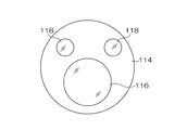
- FIG. 2 is a plan view showing a distal end surface of the endoscope insertion portion.
- FIG. 3 is an external perspective view showing a mantle tube.
- FIG. 4 is a cross-sectional view showing a reference form which is a reference of the embodiment of the present invention regarding the internal structure of the mantle tube.
- FIG. 5 is an enlarged sectional view showing a part of FIG. 4 in an enlarged manner.
- 6 is a cross-sectional view taken along the line VI-VI in FIG.
- FIG. 7 is a perspective view showing the slider (interlocking member) in the reference form of FIG. 4 from the upper left rear direction.
- FIG. 1 is a schematic configuration diagram of an endoscopic surgical apparatus according to an embodiment.
- FIG. 2 is a plan view showing a distal end surface of the endoscope insertion portion.
- FIG. 3 is an external perspective view showing a mantle tube.
- FIG. 8 is a perspective view showing the slider (interlocking member) in the reference form of FIG. 4 from the upper right rear direction.
- FIG. 9 is an explanatory diagram used for explaining the action of the slider (interlocking member) in the reference embodiment of FIG.
- FIG. 10 is an explanatory diagram used for explaining the action of the slider (interlocking member) in the reference embodiment of FIG.
- FIG. 11 is an explanatory diagram used for explaining the action of the slider (interlocking member) in the reference embodiment of FIG. FIG.
- FIG. 12 is an explanatory view showing a state of an operation when performing a treatment of an affected part in a body cavity of a patient using an endoscopic surgical apparatus, and (A) part shows a state before the operation; Part (B) shows a state in which the treatment instrument insertion part is operated forward in the dead zone area, and part (C) shows a state in which the treatment instrument insertion part is operated backward in the dead zone area.
- FIG. 12 shows an explanatory view showing a state of an operation when performing a treatment of an affected part in a body cavity of a patient using an endoscopic surgical apparatus, and (A) part shows a state before the operation; Part (B) shows a state in which the treatment instrument insertion part is operated forward in the dead zone area, and part (C) shows a state in which the treatment instrument insertion part is operated backward in the dead zone area.
- FIG. 13 is an explanatory view showing the state of the operation when performing the treatment of the affected part in the body cavity of the patient using the endoscopic surgical apparatus, and the part (A) shows the state before the operation, Part (B) shows a state in which the treatment instrument insertion part is operated forward in the sensitive zone area, and part (C) shows a state in which the treatment instrument insertion part is operated backward in the sensitive band area.
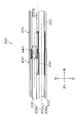
- FIG. 14 is a cross-sectional view showing the configuration of the interlocking member according to the embodiment of the present invention in a cross section obtained by cutting the mantle tube along the reference axis.
- FIG. 15 is an enlarged view showing an enlarged peripheral portion of the interlocking member in FIG.
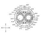
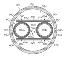
- FIG. 16 is a cross-sectional view taken along arrow XVI-XVI in FIG.
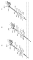
- FIG. 17 is an explanatory view used for explaining the operation of the interlocking member according to the embodiment of the present invention.
- FIG. 18 is an explanatory view used for explaining the operation of the interlocking member according to the embodiment of the present invention.
- FIG. 19 is an explanatory diagram used for explaining the operation of the interlocking member according to the embodiment of the present invention.
- FIG. 20 is a view showing another embodiment of the connecting member in the interlocking member according to the embodiment of the present invention.
- FIG. 21 is a view showing another embodiment of the first sleeve in the interlocking member according to the embodiment of the present invention.
- FIG. 1 is a schematic configuration diagram of an endoscopic surgical apparatus according to the present embodiment.
- an endoscopic surgical apparatus 10 includes an endoscope 100 that observes the inside of a patient's body cavity as one form of a first medical instrument, and a body cavity of the patient as one form of a second medical instrument.
- the first medical instrument and the second medical instrument guided by the outer tube 300 into the body cavity are not limited to a specific type, and the first medical instrument having the first insertion portion inserted into the body cavity and the body cavity Any type of second medical instrument having a second insertion portion inserted therein can be used.
- the endoscope 100 is a rigid endoscope such as a laparoscope, for example, and is inserted into a body cavity and has an insertion portion 102 (hereinafter referred to as an “endoscope insertion portion 102”) surrounded by an elongated rigid cylindrical body. And a cable portion 104 connected to the proximal end side of the endoscope insertion portion 102 and having an outer peripheral portion surrounded by an elongated soft cylindrical body.
- the cable portion 104 is a flexible cable in which a cable extending from the proximal end of the endoscope insertion portion 102 or a wire material such as a light guide is covered with a soft insulating member such as polyvinyl chloride and accommodated inside. Indicates the part.
- a connector (not shown) is provided at the end of the extension of the cable portion 104, and the processor device 108 and the light source device 110, which are control devices, are detachably connected via the connector.
- the processor device 108 is connected to the monitor 112 via a cable.
- an observation window 116 and illumination windows 118 and 118 are provided on the distal end surface 114 of the endoscope insertion portion 102.
- the observation window 116 is a component of the observation unit of the endoscope 100. Behind the observation window 116 is an objective lens of the observation optical system and a CCD (Charge Coupled Device) arranged at the imaging position of the objective lens.
- a solid-state imaging device such as an image sensor or a CMOS (Complementary Metal Oxide Semiconductor) image sensor is provided.
- a signal cable (not shown) connected to the solid-state image sensor is inserted through the endoscope insertion portion 102 and the cable portion 104 of FIG. 1 to a connector (not shown), and is connected to the processor device 108.
- the observation image captured from the observation window 116 is formed on the light receiving surface of the image sensor and converted into an electrical signal (imaging signal), and the electrical signal is output to the processor device 108 via the signal cable to be converted into a video signal. Converted.
- the video signal is output to the monitor 112 connected to the processor device 108, and an observation image (endoscopic image) is displayed on the screen of the monitor 112.
- the exit end of a light guide (not shown) is disposed behind the illumination windows 118 and 118 in FIG.
- the light guide is inserted through the endoscope insertion portion 102 and the cable portion 104 of FIG. 1 and has an incident end disposed in a connector (not shown). Accordingly, by connecting this connector to the light source device 110, the illumination light emitted from the light source device 110 is transmitted to the illumination windows 118 and 118 via the light guide, and is emitted forward from the illumination windows 118 and 118.
- two illumination windows 118 and 118 are disposed on the distal end surface 114 of the endoscope insertion portion 102, but the number of illumination windows 118 is not limited, and the number is one. It may be three or more.
- the treatment instrument 200 is made of forceps, for example, and is an elongated insertion section 202 (hereinafter referred to as “treatment instrument insertion section 202”) inserted into a body cavity, and a proximal end of the treatment instrument insertion section 202.
- treatment instrument insertion section 202 elongated insertion section 202
- An operation unit 204 provided on the side and grasped by an operator, and a treatment unit 206 provided on the distal end side of the treatment instrument insertion unit 202 and operable by operation of the operation unit 204.
- the treatment instrument insertion portion 202 is provided with a cylindrical sheath 208 and an operation shaft (not shown) that is inserted into the sheath 208 so as to be movable in the axial direction.
- the operation unit 204 is provided with a fixed handle 210 and a movable handle 214 that is rotatably connected to the fixed handle 210 via a rotation pin. The proximal end portion of the operation shaft is connected to the movable handle 214.
- the treatment section 206 is provided with a pair of gripping members that can be opened and closed. These grip members are connected to the tip of the operation shaft via a drive mechanism (not shown). Then, as the movable handle 214 of the operation unit 204 is rotated, the gripping member of the treatment unit 206 is opened and closed via the operation shaft and the drive mechanism.
- the treatment tool 200 is not limited to forceps, and may be other treatment tools such as a laser probe, a suture instrument, an electric knife, a needle holder, an ultrasonic device, and an aspirator.
- the outer tube 300 is fed out from the distal end side through the endoscope insertion portion 102 and the treatment instrument insertion portion 202 inserted inside from the proximal end side.
- the outer tube 300 is inserted into the body wall, the proximal end side is placed outside the body, and the distal end side is placed in the body cavity, so that the endoscope insertion portion 102 and the treatment instrument insertion portion 202 can be connected with one outer tube 300.
- the outer tube 300 has an interlocking function for moving the endoscope insertion portion 102 and the treatment instrument insertion portion 202 in conjunction with each other as will be described in detail later. For example, the advancement / retraction of only the treatment instrument insertion portion 202 is performed.
- the endoscope insertion unit 102 can also be moved forward and backward by the operation, and an appropriate endoscopic image can be obtained without performing the forward / backward operation of the endoscope insertion unit 102. Details of the configuration and operation of the outer tube 300 will be described later.
- FIG. 3 is an external perspective view showing the outer tube 300.
- the outer tube 300 has an elongated cylindrical shape as a whole, and is inserted into the endoscope 100 in parallel with a reference axis 300a indicating a longitudinal axis that is a central axis thereof.
- An endoscope insertion path 306 through which the portion 102 is inserted in a retractable manner and a treatment instrument insertion path 308 through which the treatment instrument insertion portion 202 of the treatment instrument 200 is inserted in an advanceable and retractable manner are provided.
- the central axis of the endoscope insertion path 306 is referred to as an endoscope insertion axis 306a and the central axis of the treatment instrument insertion path 308 is referred to as a treatment instrument insertion axis 308a
- the endoscope insertion axis 306a and the treatment instrument insertion axis 308a is parallel to each other and is also parallel to the reference axis 300a.
- the endoscope insertion shaft 306a and the treatment instrument insertion shaft 308a are the central axes of the endoscope insertion section 102 and the treatment instrument insertion section 202 inserted through the endoscope insertion path 306 and the treatment instrument insertion path 308, respectively. Corresponds to position.
- the reference shaft 300a, the endoscope insertion shaft 306a, and the treatment instrument insertion shaft 308a are arranged on the same plane.
- the reference shaft 300a, the endoscope insertion shaft 306a, and the treatment instrument insertion shaft 308a may not be arranged on the same plane.
- the direction from the proximal end surface 302 to the distal end surface 304 in the direction along the reference axis 300a is the front, and the direction from the reference axis 300a to the endoscope insertion shaft 306a.
- the direction from the reference axis 300a to the endoscope insertion shaft 306a are left, front, back, left, right, top, and bottom.
- the proximal end surface 302 of the outer tube 300 has a first proximal end opening 310 that is a proximal end opening for inserting the endoscope insertion portion 102 into the endoscope insertion passage 306, and the treatment instrument insertion portion 202 as the treatment instrument insertion passage 308.
- a second base end opening 314 which is a base end opening to be inserted into the base end is provided.
- the distal end surface 304 of the outer tube 300 is inserted into the first distal end opening 312 which is the distal end opening for feeding out the endoscope insertion portion 102 inserted into the endoscope insertion passage 306 and the treatment instrument insertion passage 308.
- a second distal end opening 316 which is a distal end opening for feeding the treatment instrument insertion portion 202 to the outside is provided.
- FIG. 4 is a cross-sectional view showing a reference form of the internal structure of the outer tube 300, which is cut along a plane including the reference axis 300a and perpendicular to the vertical direction (cut in the left-right direction along the reference axis 300a). ) Shows a cross section.
- the mantle tube 300 is attached to the mantle tube long cylindrical body 320 occupying substantially the entire front and rear direction, a base end cap 340 attached to the rear end (base end) of the mantle tube 300, and the tip portion. It has a tip cap 360 and a slider 400 which is a form of an interlocking member disposed inside the outer tube 300.
- the outer tube 320 is formed of a hard resin, metal, or the like into a long and thin cylindrical shape having the reference axis 300a as the center axis, and penetrates from the base wall to the tip of the outer tube 320 and the outer wall 322 surrounding the outer periphery. And a cavity portion 324 that has a cavity.
- the hollow portion 324 encloses a space serving as the endoscope insertion path 306 and the treatment instrument insertion path 308 and accommodates the slider 400 and the like.
- the proximal end cap 340 is formed in a columnar shape whose diameter is larger than the outer diameter of the outer cannula tube 320 by a hard resin, metal, or the like, and its rear end surface constitutes the proximal end surface 302 of the outer tube 300.
- the proximal cap 340 is provided with a through hole 342 and a through hole 344 that form a part of the endoscope insertion path 306 and the treatment instrument insertion path 308.
- the opening of the through hole 342 corresponds to the first base end opening 310 described above
- the opening of the through hole 344 corresponds to the second base end opening 314 described above.
- valve members 346 and 348 are provided in the through holes 342 and 344, respectively. These valve members 346 and 348 are opened only when the endoscope insertion portion 102 and the treatment instrument insertion portion 202 are inserted, for example, and the outer peripheral surfaces (side surfaces) of the endoscope insertion portion 102 and the treatment instrument insertion portion 202 are opened. Close contact with almost no gap. As a result, the airtightness of the space on the distal end side relative to the valve members 346 and 348 is ensured, and leakage or the like of the pneumoperitone gas injected into the body cavity is reduced.
- the front end cap 360 is formed of hard resin, metal, or the like, and the front end surface thereof constitutes the front end surface 304 of the outer tube 300.
- the distal end cap 360 is provided with a through hole 362 and a through hole 364 that form part of the endoscope insertion path 306 and the treatment instrument insertion path 308.
- the opening of the through hole 362 corresponds to the first tip opening 312 described above, and the opening of the through hole 364 corresponds to the second tip opening 316.
- tip cap 360 show one form of the structural member which comprises the outer tube 300, and the outer tube 300 is not restricted to the structure of this Embodiment.
- the outer tube long cylinder 320 and the base end cap 340, or the outer tube long tube 320 and the distal end cap 360 may be integrally formed, or may be integrally formed as a whole.
- the outer tube 300 has a cylindrical shape through which the first insertion portion of the first medical instrument and the second insertion portion of the second medical instrument are inserted, and guides the first insertion portion and the second insertion portion into the body cavity. Anything is acceptable.
- the slider 400 is accommodated in the outer tube 320 (hollow portion 324), and is supported so as to be able to advance and retract in the direction of the reference shaft 300a.
- the slider 400 is connected to the endoscope insertion portion 102 inserted into the endoscope insertion passage 306 and the treatment instrument insertion portion 202 inserted into the treatment instrument insertion passage 308, so that the endoscope insertion portion 102 and the treatment are connected.
- An embodiment of an interlocking member that interlocks with the tool insertion part 202 and moves forward and backward in the front-rear direction (axial direction) is shown.
- the slider 400 includes a dead zone region in which one of the endoscope insertion portion 102 and the treatment instrument insertion portion 202 is not interlocked with the forward / backward movement in the front-rear direction (axial direction), that is, independently moves.
- the other has a sensitive zone that interlocks with the forward and backward movement, and in the dead zone, the relative position of the distal end of the endoscope 100 with respect to the distal end of the treatment instrument 200 with respect to the reference axis 300a direction of the outer tube 300 is determined. It is an interlocking member that changes.
- the endoscope insertion portion 102 is interlocked with play by the slider 400 with respect to the forward and backward movement of the treatment instrument insertion portion 202 in the axial direction.
- FIG. 5 is an enlarged cross-sectional view showing an enlarged portion where the slider 400 is arranged in FIG. 4, and the endoscope insertion portion 102 and the treatment in each of the endoscope insertion passage 306 and the treatment instrument insertion passage 308. The state which penetrated the tool insertion part 202 is shown. 6 is a cross-sectional view taken along the line VI-VI in FIG.
- FIG 7 and 8 are perspective views showing the slider 400 from the upper left rear direction and the rear upper right direction, respectively.
- the slider 400 includes a slider body 402 that holds the components of the slider 400. As shown in FIG. 6, on the flat upper surface 404 (see FIGS. 7 and 8) and the lower surface 406 of the slider body 402, ridges 408 and 410 extending in the reference axis 300 a direction (front-rear direction) are formed.
- a pair of left and right long guide plates 374 and 374 shown in FIG. 6 spanned between the base end cap 340 and the front end cap 360 are respectively provided on the upper and lower portions in the outer tube long cylinder 320.
- the guide plates 376 and 376 are supported, and the reference shaft 300a from the proximal cap 340 to the distal cap 360 is formed by the gap between the guide plates 374 and 374 and the gap between the guide plates 376 and 376.
- Guide grooves 370 and 372 extending in the direction are formed.
- the protruding portions 408 and 410 of the slider main body 402 are fitted into the guide grooves 370 and 372 in the outer tube body 320, and the upper surface 404 and the lower surface 406 are guide plates 374 and 374, and 376 and 376, respectively. It is arranged in contact with or close to.
- the slider 400 is supported so as to be movable back and forth in the longitudinal direction of the outer tube 320, and moved in the vertical and horizontal directions and rotated in all directions (front and rear, left and right, and up and down three axes). Is regulated (at least in a state where rotation around the reference axis 300a is impossible). Further, the slider 400 moves forward and backward within a movable range in which the position where it abuts on the base end cap 340 is the rear end and the position where it abuts on the distal end cap 360 is the front end.
- the guide grooves 370 and 372 are not formed by the guide plates 374, 374, 376 and 376 arranged in the outer tube long cylinder 320, but are formed in the outer wall 322 of the outer tube long cylinder 320. It may also be formed by other configurations.
- the slider 400 includes a left endoscope connecting portion 420 that is connected (engaged) with the endoscope insertion portion 102 and a right treatment that is connected (engaged) with the treatment instrument insertion portion 202. And a tool connecting portion 422.
- the endoscope connecting portion 420 provided on the left side of the slider main body 402 secures a space that becomes the endoscope insertion passage 306 in the outer tube 320, and the endoscope insertion portion 102 as shown in FIG. Is inserted into the through hole 424 (see FIGS. 6, 7, and 8) and the outer peripheral surface (side surface) of the endoscope insertion portion 102 that is fixed to the through hole 424 and inserted into the endoscope insertion passage 306.
- the pressure contact member 426 is formed in a cylindrical shape by an elastic material such as elastic rubber as shown in FIGS. 6 and 7, and the opening 430 formed in the left side surface 431 of the slider main body 402 as shown in FIG.
- the slider body 402 is fixed by being fitted to a position coaxial with the through hole 424.
- the endoscope insertion portion 102 when the endoscope insertion portion 102 is inserted through the endoscope insertion passage 306, the endoscope insertion portion 102 passes through the through hole 424 as shown in FIG.
- the press contact member 426 is press contacted (engaged) with the outer peripheral surface, and the central axis of the endoscope insertion portion 102 is arranged coaxially with the endoscope insertion shaft 306a.
- the endoscope insertion portion 102 and the slider 400 (slider main body 402) are coupled (engaged) in an interlocking manner via the pressure contact member 426, and the endoscope insertion portion 102 is advanced and retracted in the front-rear direction (axial direction). In conjunction with the movement, the slider 400 (slider main body 402) also moves forward and backward integrally.
- the position at which 400 is engaged can be arbitrarily adjusted.
- the treatment instrument connecting portion 422 provided on the right side of the slider main body 402 includes a sleeve 440 (see FIGS. 6 and 8) connected to the treatment instrument insertion portion 202 and a sleeve 440 as shown in FIG. And a guide portion 460 that guides the guide so as to be movable forward and backward.
- the sleeve 440 includes a sleeve main body 444 (frame body) formed in a cylindrical shape, and a pressure contact member 446 fixed to the inside of the sleeve main body 444.
- the pressure contact member 446 is formed in a cylindrical shape by an elastic material such as elastic rubber.
- the treatment instrument insertion portion 202 when the treatment instrument insertion portion 202 is inserted into the treatment instrument insertion path 308, the treatment instrument insertion portion 202 is inserted through the inside of the pressure contact member 446 (through hole 450 in FIG. 6) as shown in FIG.
- the pressure contact member 446 is in pressure contact (engagement) with the outer peripheral surface of the treatment instrument insertion portion 202, and the central axis of the treatment instrument insertion portion 202 is arranged coaxially with the treatment instrument insertion shaft 308a.
- the treatment instrument insertion portion 202 and the sleeve 440 are connected to each other via a pressure contact member 446 so that the treatment instrument insertion portion 202 can be interlocked, and the sleeve 440 is also integrally interlocked with the forward and backward movement of the treatment instrument insertion portion 202 in the front-rear direction (axial direction). Move forward and backward.
- the sleeve 440 rotates with respect to the slider main body 402 in conjunction with the rotation around the axis of the treatment instrument insertion portion 202.
- connection between the treatment instrument insertion portion 202 and the sleeve 440 is due to the elastic force of the pressure contact member 446, and therefore, the engagement position of the treatment instrument insertion portion 202 connected to the sleeve 440 (the treatment instrument insertion portion).
- the position at which the sleeve 440 is engaged at 202 can be arbitrarily adjusted.
- the guide portion 460 of the treatment instrument connecting portion 422 is, as shown in FIGS. 6 and 8, the slider body 402 extending in the direction of the reference axis 300a (treatment instrument insertion shaft 308a) in the hollow portion 324 of the outer tube 320. Is formed by a space surrounded by the guide surface 462 and the inner peripheral surface of the outer tubular tube 320.
- the sleeve 440 is accommodated and disposed in the space of the guide portion 460, is supported so as to be movable in the front-rear direction and to be rotatable around the axis, and is supported in a state where movement in the vertical and horizontal directions is restricted.
- guide portion 460 is provided so as to be within a range from the proximal end to the distal end of the slider main body 402, and as shown in FIGS. 5 and 8, guide portions 460 are provided on the proximal end side and the distal end side of the slider main body 402, respectively. End edges 466 and 468 are formed along the edge of the surface 462 so as to project in a direction perpendicular to the guide surface 462.
- end edge portions 466 and 468 abut against the end portion of the sleeve 440 and restrict the movement of the sleeve 440 when the sleeve 440 disposed in the space of the guide portion 460 moves forward and backward.
- the sleeve 440 moves back and forth within a movable range in which the position where the end edge 466 abuts is the rear end and the position where the end edge 468 abuts is the front end.
- the mantle tube 300 is inserted into the body wall of the patient, and insufflation gas is injected into the body cavity.
- the endoscope 100 (endoscope insertion part 102) and the treatment tool 200 (treatment tool insertion part 202) are inserted into each of the tool insertion passages 308, and the endoscope insertion part 102 and the treatment tool are inserted into the outer tube 300.
- the unit 202 is attached.
- the endoscope insertion portion 102 is connected to the slider main body 402 of the slider 400, and the treatment instrument insertion portion 202 is connected to the sleeve 440 of the slider 400.
- the state of the part (A) in FIG. 12 is a state in which the sleeve 440 has not reached either the front end or the rear end of the movable range with respect to the slider main body 402 (guide part 460) as shown in FIG. Then, when the surgeon makes a slight advance of the treatment instrument insertion section 202 with the hand holding the operation section 204 of the treatment instrument 200, the slider main body 402 moves relative to the outer tube 300 (outer tube long tubular body 320). Without moving, only the sleeve 440 moves forward with respect to the slider body 402 within a movable range with respect to the slider body 402.
- the endoscope insertion portion 102 is moved as shown in FIG. Only the treatment instrument insertion portion 202 advances in a stationary state. That is, the slider 400 has a dead zone area where the endoscope insertion section 102 is not interlocked with the advance / retreat movement of the treatment instrument insertion section 202, and the forward operation of the treatment instrument 200 at this time advances / retreats in the dead zone area of the slider 400. It becomes operation.
- the surgeon can When the treatment instrument insertion unit 202 is slightly retracted with the hand holding the operation unit 204, the slider main body 402 does not move with respect to the outer tube 300 (outer tube long tubular body 320), but with respect to the slider main body 402. Only the sleeve 440 moves backward within a movable range with respect to the slider body 402.
- the endoscope 100 does not move back and forth with respect to a minute advance / retreat operation of the treatment instrument 200, that is, an advance / retreat operation in the dead zone region, and thus the treatment instrument 200 displayed as an endoscopic image on the monitor 112.
- the range of the observation site such as the distal end site or the body cavity site does not change, and the size of the image of the observation site can be prevented from changing according to the minute displacement of the treatment tool 200.
- a sense of perspective can be appropriately maintained, and a stable endoscopic image can be obtained.
- FIG. 13A shows the same state as the portion (A) of FIG.
- the endoscope insertion portion 102 moves forward in conjunction with the treatment instrument insertion portion 202 as shown in FIG.
- the slider 400 has a sensitive zone region in which the endoscope insertion portion 102 is interlocked with the advance and retreat movement of the treatment instrument insertion portion 202, and the forward operation of the treatment instrument 200 at this time is the sensitive zone region of the slider 400. This is a forward operation.
- the operator holds the operation unit 204 of the treatment instrument 200.
- the sleeve 440 is moved back in the dead zone until the sleeve 440 of the slider 400 comes into contact with the rear end of the movable range, as shown in FIG. The rear end of the movable range with respect to the main body 402 is reached.
- the sleeve 440 and the slider main body 402 move backward with respect to the outer tube tube 320 together with the treatment tool insertion portion 202, and the endoscope insertion portion 102 moves to the treatment instrument insertion portion. It moves backward in conjunction with 202. Therefore, with respect to the backward movement of the treatment instrument insertion portion 202 after the sleeve 440 reaches the rear end of the movable range with respect to the slider main body 402, as shown in FIG. In conjunction with this, the endoscope insertion portion 102 moves backward. That is, the backward operation of the treatment instrument 200 at this time is a backward operation in the zone of the slider 400.
- the endoscope 100 moves forward / backward, so that the observation reflected in the endoscopic image displayed on the monitor 112 is observed.
- the range of the part is continuously changed so as to follow the advance / retreat movement of the treatment instrument 200.
- the endoscope insertion portion 102 moves forward and backward in conjunction with the front, rear, up, down, left and right, the field of view and orientation of the endoscope 100 can be changed as intended by the operator.
- the visual field always images the distal end portion of the treatment tool 200, and an optimal image for treatment is automatically provided.
- an assistant who operates the endoscope 100 separately from the surgeon can be eliminated, and the surgeon must sequentially indicate the field of view, orientation, and the like of the endoscope 100 to the assistant. The troublesomeness can be eliminated.
- the endoscope insertion unit 102 does not interlock, and thus the endoscope image changes unnecessarily. Can be prevented, a sense of perspective can be appropriately maintained, and a stable endoscopic image can be provided.
- the slider 400 is employed as an interlocking member for interlocking the endoscope insertion portion 102 and the treatment instrument insertion portion 202.
- the slider 400 has a simple configuration.
- An interlocking member that is similar to the slider 400 and that is similar to the slider 400 is employed.
- FIG. 14 is a cross-sectional view showing the configuration of the interlocking member 600 according to the embodiment of the present invention in a cross-section obtained by cutting the outer tube 300 along the reference axis 300a
- FIG. 15 is a cross-sectional view of the interlocking member 600 in FIG. It is the enlarged view which expanded and showed the peripheral part.
- 16 is a cross-sectional view taken along arrow XVI-XVI in FIG.
- FIG. 15 shows a state in which the endoscope insertion section 102 and the treatment instrument insertion section 202 are inserted through the endoscope insertion path 306 and the treatment instrument insertion path 308 of the outer tube 300.
- the interlocking member 600 includes a first sleeve 602 as a first holding portion for holding the endoscope insertion portion 102 inserted through the endoscope insertion passage 306 of the outer tube 300, and the outer tube 300.
- a second sleeve 604 as a second holding portion for holding the treatment instrument insertion portion 202 inserted through the treatment instrument insertion path 308, and a connecting member 606 for connecting the first sleeve 602 and the second sleeve 604.
- the first sleeve 602 is configured in the same manner as the sleeve 440 in the slider 400 of the above-described embodiment, for example, and a sleeve main body 620 that is a frame formed in a cylindrical shape as shown in FIGS. 15 and 16, and the sleeve main body 620. And a pressure contact member 622 formed in a cylindrical shape by an elastic material.
- the second sleeve 604 is a cylindrical frame body 640 as shown in FIGS. 15 and 16, and a sleeve body 640 is fixed to the inside of the sleeve body 640, and is pressed into a cylindrical shape by an elastic material. Member 642.
- the upper and lower portions of the outer tube 300 are formed by the guide plates 374 and 374 and the guide plates 376 and 376 shown in FIG. Similar to the guide grooves 370 and 372, guide plates 660, 662 and 664 extending along the reference axis 300a direction and guide plates 666, 668 and 670 are hung between the proximal cap 340 and the distal cap 360.
- the guide plates 660, 662, and 664 and the guide plates 666, 668, and 670 form guide grooves 672 and 674 that extend along the direction of the reference axis 300a, and guide grooves 676 and 678. .
- ridges 680 and 682 extending in the axis 300a direction (front-rear direction) are formed.
- Each of the ridges 680 and 682 is inserted into the guide grooves 672 and 676, and the outer peripheral surface of the first sleeve 602 is disposed in contact with or close to the guide plates 660, 662, 666, and 668.
- convex strips 684 and 686 extending in the direction of the shaft 300a (front-rear direction) are formed on the upper and lower portions of the outer peripheral surface of the second sleeve 604 (sleeve body 640).
- Each of the ridges 684 and 686 is inserted into the guide grooves 674 and 678, and the outer peripheral surface of the second sleeve 604 is disposed in contact with or close to the guide plates 662, 664, 668 and 670.
- the first sleeve 602 is supported so that its central axis is arranged substantially coaxially with the endoscope insertion shaft 306a, can move forward and backward in the front-rear direction, and cannot rotate around the central axis.
- the center axis of the second sleeve 604 is disposed substantially coaxially with the treatment instrument insertion shaft 308a, and is supported so that it can move forward and backward in the front-rear direction and cannot rotate around the center axis.
- the mechanism for supporting the first sleeve 602 and the second sleeve 604 so as to be able to advance and retreat in the direction of the reference axis 300a of the outer tube 300 may be different from the present embodiment.
- the treatment instrument insertion portion 202 when the treatment instrument insertion portion 202 is inserted into the treatment instrument insertion passage 308, the treatment instrument insertion portion 202 is inserted into the through hole 604 a of the second sleeve 604 (the through hole on the inner peripheral side of the pressure contact member 642. 604a, see FIG. 16), and the pressure contact member 642 presses (engages) the outer peripheral surface of the treatment instrument insertion portion 202. Thereby, the 2nd sleeve 604 and the treatment tool insertion part 202 connect.
- the connecting member 606 is, for example, a non-stretchable and flexible string-like flexible member. As shown in FIGS. 15 and 16, one first end 606 a serves as a first fixing portion. The other second end 606b is fixed to the first sleeve 602, and the other second end 606b is fixed to the second sleeve 604 as a second fixing portion.
- the first end 606a is, for example, the right side of the outer peripheral surface of the first sleeve 602 and is fixed near the center in the front-rear direction
- the second end 606b is, for example, the left side of the outer peripheral surface of the second sleeve 604 It is fixed on the side and near the center in the front-rear direction.
- first fixing position in the first sleeve 602 to which the first end 606a is fixed and the second fixing position in the second sleeve 604 to which the second end 606b is fixed are not limited to specific positions.
- the connecting member 606 When the position of the first end portion 606a and the second end portion 606b coincides with the front-rear direction, the connecting member 606 is loosened (bent) between the first end portion 606a and the second end portion 606b. Has a slack that occurs.
- the entire connecting member 606 is a slack portion, but a part of the connecting member 606 is a hard member that cannot be deformed, and only a part of the connecting member 606 is formed. The form used as a slack part may be sufficient.
- the slack portion Elongates and creates a tensile force between the first end 606a and the second end 606b.
- the slack portion of the connecting member 606 has a first fixing position of the first sleeve 602 to which the first end portion 606a is fixed and a second fixing position of the second sleeve 604 to which the second end portion 606b is fixed.
- the slack portion is slack when the minimum length Lmin of the slack portion required when connecting by the connecting member 606 is shorter than the actual length L of the slack portion, and Lmin matches L In this state, the slack portion is extended.
- the connecting member 606 has a length from the first end portion 606a to the second end portion 606b, and the endoscope insertion portion 102 and the treatment instrument insertion portion 202 in the outer tube 300. Longer than the shortest distance and shorter than the length of the outer tube 300 in the direction of the reference axis 300a.
- the state of the slack portion of the connecting member 606 is changed by the relative movement of the first sleeve 602 and the second sleeve 604 in the front-rear direction, so that the connecting member 606 is in the relaxed state. It changes between the tension state. That is, the connecting member 606 changes between a relaxed state when the slack portion is slack and a tension state when the slack portion is extended.
- the first sleeve 602 and the second sleeve 604 in the front-rear direction is a positional relationship that causes the connecting member 606 to be in a relaxed state
- the first sleeve 602 and the second sleeve 604. Is in a non-interlocking state in which and move independently.
- the interlocking member 600 exhibits the same operations and effects as the slider 400 of the reference embodiment.
- the interlocking member 600 is connected to the endoscope insertion portion 102 inserted into the endoscope insertion passage 306 of the outer tube 300 and the treatment instrument insertion portion 202 inserted into the treatment instrument insertion passage 308, and There is a dead zone region in which the other is not interlocked with respect to the forward / backward movement in one longitudinal direction (axial direction), and a sensitive zone region in which the other is interlocked with respect to any one of the forward / backward movements. It acts as a means for changing the relative position of the distal end of the endoscope 100 with respect to the distal end of the treatment instrument 200 with respect to the reference axis 300a direction.
- FIG. 9 of the slider 400 of the above embodiment corresponds to the state in FIG. 15 of the interlocking member 600 of the present embodiment.
- FIG. ) Portion or the portion (C) of FIG. 12 the endoscope insertion portion 102 is kept stationary with respect to the minute movement of the treatment instrument insertion portion 202.
- each of the states in FIGS. 10 and 11 of the slider 400 of the above embodiment corresponds to each of the states in FIGS. 17 and 18 of the interlocking member 600 of the present embodiment, and in these states, FIG.
- the endoscope insertion section 102 moves forward and backward in conjunction with the forward and backward movement of the treatment instrument insertion section 202.
- the interlocking member 600 according to the embodiment of the present invention has a simpler structure than the case where the interlocking member is the slider 400, so that the outer tube 300 can be reduced in cost, simplified in structure, reduced in diameter, and the like. be able to.
- the connecting member 606 is a non-stretchable and string-like flexible member, but the first sleeve 602 and the second sleeve 604 are not necessarily string-like. Any one that changes between a relaxed state and a tensile state according to a change in relative position may be used.
- the connecting member 606 may have a strip shape as shown in FIG. In this case, the connecting member 606 is arranged so that the connecting member 606 can be deformed in a direction perpendicular to the vertical direction.
- the connecting member 606 directly connects the first sleeve 602 and the second sleeve 604.
- the present invention is not limited to this, and the first sleeve 602 is not limited thereto.
- the first sleeve 602 and the second sleeve 604 are connected so that when one of the second sleeve 604 is moved forward or backward relative to the other, the state is switched from the relaxed state to the tensile state. That's fine.
- the connecting member 700 shown in FIG. 20 is hung at the upper or lower part inside the outer tube 300 at positions of the proximal end side and the distal end side along the endoscope insertion passage 306 and the treatment instrument insertion passage 308, respectively.
- Members 702, 704, 706, and 708 are provided, and a string-like or belt-like connecting member 700 is stretched around the hook members 702, 704, 706, and 708 in the shape of an eight.
- the first sleeve 602 is fixed to a portion of the connecting member 700 that is spanned between the hanging member 702 and the hanging member 704, and the first portion is stretched to the portion that is spanned between the hanging member 706 and the hanging member 708.
- the two sleeves 604 are fixed.
- the entire connecting member 700 is set in a relaxed state. . Then, when one of the first sleeve 602 and the second sleeve 604 moves forward or backward relative to the other with respect to the state, the connection for connecting the first sleeve 602 and the second sleeve 604 is performed.
- One of the two sections of the member 700 is in a tensile state, and the first sleeve 602 and the second sleeve 604 move in conjunction with each other.
- the connecting member 700 extends from the second sleeve 604 to the proximal end side and extends through the hanging member 706 and the hanging member 704.
- a portion connected to one sleeve 602 is in a tensile state.
- the first sleeve 602 moves forward in conjunction with the forward movement of the second sleeve 604.
- the first sleeve 602 and the second sleeve 604 are restricted from rotating around the respective central axes, and the endoscope insertion portion 102 and the treatment tool connected to them are connected.
- the rotation of the insertion portion 202 around the axis is also restricted.
- either one or both of the endoscope insertion portion 102 and the treatment instrument insertion portion 202 may be rotated around the axis.
- the second sleeve 604 may be configured as shown in the cross-sectional view of FIG.
- the second sleeve 604 includes the above-described cylindrical sleeve body 640, and a cylindrical intermediate frame 720 that is rotatably supported around the central axis with respect to the sleeve body 640 on the inner peripheral side of the sleeve body 640.
- the cylindrical pressure contact member 642 is fixed to the inner peripheral side of the intermediate frame 720.
- the first sleeve 602 can also be configured in the same manner as the second sleeve 604 of FIG.
- the reference shaft 300a, the endoscope insertion shaft 306a, and the treatment instrument insertion shaft 308a are parallel to each other. However, the endoscope insertion with respect to the reference shaft 300a is performed. At least one of the shaft 306a and the treatment instrument insertion shaft 308a may be oblique (non-parallel).
- a plane including the reference axis 300a and having the normal direction in the vertical direction is referred to as a horizontal reference plane
- a plane including the reference axis 300a and having the horizontal direction as the normal is referred to as a vertical reference plane
- the reference axis 300a, the endoscope insertion axis 306a, and the treatment instrument insertion axis 308a are all parallel on the horizontal reference plane when the shaft 306a and the treatment instrument insertion axis 308a are projected onto the horizontal reference plane.
- the reference axis 300a and the treatment instrument insertion axis 308a are parallel to each other, but the reference axis 300a and the endoscope
- the endoscope insertion shaft 306a may be non-parallel and the endoscope insertion shaft 306a may be inclined obliquely from the lower rear side toward the upper front side.
- the outer tube 300 guides the endoscope insertion portion 102 in an oblique direction with respect to the guide direction of the treatment instrument insertion portion 202, and the distal end portion of the treatment portion 206 at the distal end of the treatment instrument insertion portion 202 is a blind spot.
- the distal end of the treatment section 206 is placed on the observation image by widening the interval between the observation section (observation window 116) at the distal end of the endoscope insertion section 102 and the treatment section 206 at the distal end of the treatment instrument insertion section 202 so Can be made visible.
- Endoscopic surgical apparatus 100 Endoscope 102 Endoscope insertion part 104 Cable part 108 Processor apparatus 110 Light source apparatus 112 Monitor 116 Observation window 118 Illumination window 200 Treatment tool 202 Treatment tool insertion part 204 Operation part 206 Treatment part 300 Outer tube 300a Reference shaft 302 Base end face 304 End face 306 Endoscope insertion path 306a Endoscope insertion shaft 308 Treatment instrument insertion path 308a Treatment instrument insertion shaft 310 First proximal end opening 312 First distal end opening 314 Second proximal end opening 316 Second distal end opening 320 Mantle tube long cylindrical body 322 Outer wall 324 Cavity 340 Base end cap 342, 344 Through hole 346, 348 Valve member 360 End cap 362, 364 Through hole 370, 372 Guide groove 374, 376 Guide plate 400 Slider 402 Slider body 404 Upper surface 406 Lower surface 408, 410 Convex section 420 Endoscope connection section 422 Treatment instrument connection section 424 Through
Abstract
L'invention fournit un dispositif pour opération chirurgicale destiné à un endoscope satisfaisant le fonctionnement conjoint de deux instruments médicaux dans un tube d'enveloppe extérieure, et permettant un abaissement des coûts et une simplification de sa configuration, en outre, l'invention fournit un dispositif de guidage. Le tube d'enveloppe extérieure (300) qui est piqué au travers d'une paroi corporelle, et qui guide un endoscope et un appareil de traitement à l'intérieur d'une cavité corporelle, est équipé d'un élément fonctionnement conjoint (600) mettant conjointement en déplacement d'avancée/recul l'endoscope et l'appareil de traitement. L'élément fonctionnement conjoint (600) est configuré par un premier manchon (602) raccordé à l'endoscope, un second manchon (604) raccordé à l'appareil de traitement, et un élément raccordement (606) flexible sous forme de corde raccordant le premier manchon (602) et le second manchon (604). Ainsi, dans un état de relâchement de l'élément raccordement (606) l'endoscope et l'appareil de traitement se déplacent en avancée/recul de manière indépendante, et dans un état de tension de l'élément raccordement (606), l'endoscope et l'appareil de traitement se déplacent en avancée/recul de manière conjointe.
Priority Applications (2)
| Application Number | Priority Date | Filing Date | Title |
|---|---|---|---|
| JP2017531105A JP6531174B2 (ja) | 2015-07-30 | 2016-07-05 | 内視鏡用外科手術装置及び案内装置 |
| US15/883,101 US10542869B2 (en) | 2015-07-30 | 2018-01-30 | Endoscopic surgical device and guide device |
Applications Claiming Priority (2)
| Application Number | Priority Date | Filing Date | Title |
|---|---|---|---|
| JP2015150827 | 2015-07-30 | ||
| JP2015-150827 | 2015-07-30 |
Related Child Applications (1)
| Application Number | Title | Priority Date | Filing Date |
|---|---|---|---|
| US15/883,101 Continuation US10542869B2 (en) | 2015-07-30 | 2018-01-30 | Endoscopic surgical device and guide device |
Publications (1)
| Publication Number | Publication Date |
|---|---|
| WO2017018139A1 true WO2017018139A1 (fr) | 2017-02-02 |
Family
ID=57884633
Family Applications (1)
| Application Number | Title | Priority Date | Filing Date |
|---|---|---|---|
| PCT/JP2016/069922 WO2017018139A1 (fr) | 2015-07-30 | 2016-07-05 | Dispositif pour opération chirurgicale destiné à un endoscope, et dispositif de guidage |
Country Status (3)
| Country | Link |
|---|---|
| US (1) | US10542869B2 (fr) |
| JP (1) | JP6531174B2 (fr) |
| WO (1) | WO2017018139A1 (fr) |
Citations (1)
| Publication number | Priority date | Publication date | Assignee | Title |
|---|---|---|---|---|
| WO2015033909A1 (fr) * | 2013-09-03 | 2015-03-12 | 富士フイルム株式会社 | Dispositif chirurgical endoscopique et manchon externe |
Family Cites Families (1)
| Publication number | Priority date | Publication date | Assignee | Title |
|---|---|---|---|---|
| JP4594612B2 (ja) * | 2003-11-27 | 2010-12-08 | オリンパス株式会社 | 挿入補助具 |
-
2016
- 2016-07-05 JP JP2017531105A patent/JP6531174B2/ja active Active
- 2016-07-05 WO PCT/JP2016/069922 patent/WO2017018139A1/fr active Application Filing
-
2018
- 2018-01-30 US US15/883,101 patent/US10542869B2/en active Active
Patent Citations (1)
| Publication number | Priority date | Publication date | Assignee | Title |
|---|---|---|---|---|
| WO2015033909A1 (fr) * | 2013-09-03 | 2015-03-12 | 富士フイルム株式会社 | Dispositif chirurgical endoscopique et manchon externe |
Also Published As
| Publication number | Publication date |
|---|---|
| US10542869B2 (en) | 2020-01-28 |
| US20180153378A1 (en) | 2018-06-07 |
| JPWO2017018139A1 (ja) | 2018-05-17 |
| JP6531174B2 (ja) | 2019-06-12 |
Similar Documents
| Publication | Publication Date | Title |
|---|---|---|
| JP6266755B2 (ja) | 内視鏡用外科手術装置、処置具、及びガイド部材 | |
| JP6580755B2 (ja) | 内視鏡用外科手術装置及び外套管 | |
| JP5976924B2 (ja) | 内視鏡下外科手術装置 | |
| US20160174820A1 (en) | Endoscopic surgical device and outer sleeve | |
| JP6286575B2 (ja) | 内視鏡用外科手術装置 | |
| JP6266756B2 (ja) | 外装管及び内視鏡用外科手術装置 | |
| JP6018295B2 (ja) | 医療器具案内装置 | |
| JP6266754B2 (ja) | 内視鏡用外科手術装置、内視鏡、及び内視鏡操作具 | |
| JP6346941B2 (ja) | 内視鏡用外科手術装置及び外套管 | |
| JP6259528B2 (ja) | 内視鏡用外科手術装置 | |
| JP6368426B2 (ja) | 内視鏡用外科手術装置 | |
| JP6396595B2 (ja) | 内視鏡用外科手術装置及び案内装置 | |
| WO2017018139A1 (fr) | Dispositif pour opération chirurgicale destiné à un endoscope, et dispositif de guidage | |
| JP6286576B2 (ja) | 内視鏡用外科手術装置及び外装管 | |
| JP6266753B2 (ja) | 内視鏡用外科手術装置及び外套管 |
Legal Events
| Date | Code | Title | Description |
|---|---|---|---|
| 121 | Ep: the epo has been informed by wipo that ep was designated in this application |
Ref document number: 16830244 Country of ref document: EP Kind code of ref document: A1 |
|
| ENP | Entry into the national phase |
Ref document number: 2017531105 Country of ref document: JP Kind code of ref document: A |
|
| NENP | Non-entry into the national phase |
Ref country code: DE |
|
| 122 | Ep: pct application non-entry in european phase |
Ref document number: 16830244 Country of ref document: EP Kind code of ref document: A1 |