WO2017018028A1 - 電解コンデンサ電極用アルミニウム材の製造方法、アルミニウム電解コンデンサ用電極材の製造方法、およびアルミニウム電解コンデンサの製造方法 - Google Patents
電解コンデンサ電極用アルミニウム材の製造方法、アルミニウム電解コンデンサ用電極材の製造方法、およびアルミニウム電解コンデンサの製造方法 Download PDFInfo
- Publication number
- WO2017018028A1 WO2017018028A1 PCT/JP2016/064768 JP2016064768W WO2017018028A1 WO 2017018028 A1 WO2017018028 A1 WO 2017018028A1 JP 2016064768 W JP2016064768 W JP 2016064768W WO 2017018028 A1 WO2017018028 A1 WO 2017018028A1
- Authority
- WO
- WIPO (PCT)
- Prior art keywords
- aluminum material
- temperature
- electrolytic capacitor
- aluminum
- less
- Prior art date
- Legal status (The legal status is an assumption and is not a legal conclusion. Google has not performed a legal analysis and makes no representation as to the accuracy of the status listed.)
- Ceased
Links
Images
Classifications
-
- B—PERFORMING OPERATIONS; TRANSPORTING
- B21—MECHANICAL METAL-WORKING WITHOUT ESSENTIALLY REMOVING MATERIAL; PUNCHING METAL
- B21B—ROLLING OF METAL
- B21B1/00—Metal-rolling methods or mills for making semi-finished products of solid or profiled cross-section; Sequence of operations in milling trains; Layout of rolling-mill plant, e.g. grouping of stands; Succession of passes or of sectional pass alternations
- B21B1/22—Metal-rolling methods or mills for making semi-finished products of solid or profiled cross-section; Sequence of operations in milling trains; Layout of rolling-mill plant, e.g. grouping of stands; Succession of passes or of sectional pass alternations for rolling plates, strips, bands or sheets of indefinite length
- B21B1/24—Metal-rolling methods or mills for making semi-finished products of solid or profiled cross-section; Sequence of operations in milling trains; Layout of rolling-mill plant, e.g. grouping of stands; Succession of passes or of sectional pass alternations for rolling plates, strips, bands or sheets of indefinite length in a continuous or semi-continuous process
- B21B1/26—Metal-rolling methods or mills for making semi-finished products of solid or profiled cross-section; Sequence of operations in milling trains; Layout of rolling-mill plant, e.g. grouping of stands; Succession of passes or of sectional pass alternations for rolling plates, strips, bands or sheets of indefinite length in a continuous or semi-continuous process by hot-rolling, e.g. Steckel hot mill
-
- B—PERFORMING OPERATIONS; TRANSPORTING
- B21—MECHANICAL METAL-WORKING WITHOUT ESSENTIALLY REMOVING MATERIAL; PUNCHING METAL
- B21B—ROLLING OF METAL
- B21B3/00—Rolling materials of special alloys so far as the composition of the alloy requires or permits special rolling methods or sequences ; Rolling of aluminium, copper, zinc or other non-ferrous metals
-
- C—CHEMISTRY; METALLURGY
- C22—METALLURGY; FERROUS OR NON-FERROUS ALLOYS; TREATMENT OF ALLOYS OR NON-FERROUS METALS
- C22C—ALLOYS
- C22C21/00—Alloys based on aluminium
-
- C—CHEMISTRY; METALLURGY
- C22—METALLURGY; FERROUS OR NON-FERROUS ALLOYS; TREATMENT OF ALLOYS OR NON-FERROUS METALS
- C22F—CHANGING THE PHYSICAL STRUCTURE OF NON-FERROUS METALS AND NON-FERROUS ALLOYS
- C22F1/00—Changing the physical structure of non-ferrous metals or alloys by heat treatment or by hot or cold working
-
- C—CHEMISTRY; METALLURGY
- C22—METALLURGY; FERROUS OR NON-FERROUS ALLOYS; TREATMENT OF ALLOYS OR NON-FERROUS METALS
- C22F—CHANGING THE PHYSICAL STRUCTURE OF NON-FERROUS METALS AND NON-FERROUS ALLOYS
- C22F1/00—Changing the physical structure of non-ferrous metals or alloys by heat treatment or by hot or cold working
- C22F1/04—Changing the physical structure of non-ferrous metals or alloys by heat treatment or by hot or cold working of aluminium or alloys based thereon
-
- C—CHEMISTRY; METALLURGY
- C25—ELECTROLYTIC OR ELECTROPHORETIC PROCESSES; APPARATUS THEREFOR
- C25F—PROCESSES FOR THE ELECTROLYTIC REMOVAL OF MATERIALS FROM OBJECTS; APPARATUS THEREFOR
- C25F3/00—Electrolytic etching or polishing
- C25F3/02—Etching
- C25F3/04—Etching of light metals
-
- H—ELECTRICITY
- H01—ELECTRIC ELEMENTS
- H01G—CAPACITORS; CAPACITORS, RECTIFIERS, DETECTORS, SWITCHING DEVICES, LIGHT-SENSITIVE OR TEMPERATURE-SENSITIVE DEVICES OF THE ELECTROLYTIC TYPE
- H01G9/00—Electrolytic capacitors, rectifiers, detectors, switching devices, light-sensitive or temperature-sensitive devices; Processes of their manufacture
-
- H—ELECTRICITY
- H01—ELECTRIC ELEMENTS
- H01G—CAPACITORS; CAPACITORS, RECTIFIERS, DETECTORS, SWITCHING DEVICES, LIGHT-SENSITIVE OR TEMPERATURE-SENSITIVE DEVICES OF THE ELECTROLYTIC TYPE
- H01G9/00—Electrolytic capacitors, rectifiers, detectors, switching devices, light-sensitive or temperature-sensitive devices; Processes of their manufacture
- H01G9/004—Details
- H01G9/04—Electrodes or formation of dielectric layers thereon
- H01G9/048—Electrodes or formation of dielectric layers thereon characterised by their structure
- H01G9/055—Etched foil electrodes
Definitions
- the present invention relates to a method for producing an aluminum material for an electrolytic capacitor electrode, a method for producing an electrode material for an aluminum electrolytic capacitor, and a method for producing an aluminum electrolytic capacitor.
- aluminum is used to include its alloys.
- An aluminum material generally used for an aluminum electrolytic capacitor electrode is subjected to an etching process in order to expand its effective area and increase the capacitance per unit area.
- direct current etching is often selected as the etching processing method.
- the occupation ratio of the cubic orientation grains hereinafter also referred to as ⁇ 100 ⁇ area ratio
- the effect of the surface expansion treatment by etching cannot be sufficiently obtained. That is, in order to obtain a high capacitance, an aluminum material whose ⁇ 100 ⁇ area ratio is high and uniform regardless of the location of the aluminum material is required.
- Patent Document 1 and Patent Document 2 disclose that the crystal grain size in the hot rolling process is fine by controlling the plate thickness and reduction ratio of the aluminum material obtained by the hot rolling process.
- the technology to be converted is disclosed.
- Patent Document 3 discloses a technique for refining crystal grains in a hot rolling process by controlling temperature conditions in the hot rolling process.
- Patent Document 4 discloses a technique for defining a hot rolling start temperature or bringing a brush roll into contact with a work roll in hot rolling.
- Japanese Patent Laid-Open No. 10-53826 Japanese Patent Laid-Open No. 10-330873 Japanese Patent No. 7-211591 Japanese Patent No. 2008-144255
- the temperature of the aluminum material in the hot rolling process varies greatly depending on the part, and the cause of such temperature variations is hot rolled sheet It is conceivable that the temperature tends to decrease locally in the vicinity of the contact portion with the transport roller.
- the conventional method for producing an aluminum material for electrolytic capacitor electrodes it has not been studied to suppress this by paying attention to the temperature variation of the aluminum material in the hot rolling process.
- Patent Document 4 since the technique described in Patent Document 4 has a relatively low hot rolling start temperature, there is a limitation in controlling the etching characteristics of the obtained aluminum material for electrolytic capacitor electrodes.
- the present invention has been made in view of such a situation, and it is possible to make crystal grains fine and uniform, and has a high ⁇ 100 ⁇ area ratio and a high capacitance electrolysis having excellent etching characteristics.
- An object of the present invention is to provide a method for producing an aluminum material for an electrolytic capacitor electrode capable of producing an aluminum material for a capacitor electrode, and further to provide an aluminum material for an electrolytic capacitor electrode, an electrode material for an electrolytic capacitor, and an aluminum electrolytic capacitor. .
- the inventors have intensively studied, and by precisely controlling the temperature of the aluminum material in the hot rolling process, the crystal grains after hot rolling can be made fine and uniform, ⁇ 100 ⁇
- the inventors have found that an aluminum material with a high area ratio can be obtained, and have completed the present invention.
- the manufacturing method of the aluminum material for electrolytic capacitor electrodes and the manufacturing method of the electrolytic capacitor electrode material of the present invention have the following configurations.
- the hot rolling process includes a rolling process of three or more passes including a first pass and a final pass
- the temperature control timing is a timing at which the temperature of the center part in the width direction and the longitudinal direction of the aluminum material is 400 ° C. or more and 500 ° C. or less immediately before the pass among the passes other than the first pass and the final pass
- the temperature difference in the entire aluminum material at the temperature management timing is 40 ° C.
- the overall temperature difference of the aluminum material is the total width from both ends in the width direction of the aluminum material for each of the three portions, 1.5 m inside from the both ends in the longitudinal direction of the aluminum material and the central portion in the longitudinal direction.
- the hot rolling process includes a rolling process of three or more passes including the first pass and the final pass, and immediately before the pass among the passes excluding the first pass and the final pass,
- the temperature control timing is the timing at which the temperature in the center in the width direction and the longitudinal direction of the aluminum material is 400 ° C. or more and 500 ° C. or less
- the temperature difference in the entire aluminum material at the temperature management timing is 40 ° C. or less.
- the crystal grains can be made fine and uniform, has a high ⁇ 100 ⁇ area ratio, has excellent etching characteristics, and has a large capacitance. It is possible to produce a non-material.
- the temperature of the center part in the width direction and the longitudinal direction of the aluminum material at the temperature control timing is 420 ° C. or more and 480 ° C. or less, it has a higher ⁇ 100 ⁇ area ratio.
- an aluminum material for an electrolytic capacitor electrode having further excellent etching characteristics can be produced.
- the thickness of the aluminum material at the temperature control timing is 10 mm or more and 100 mm or less, it is possible to reliably realize a high ⁇ 100 ⁇ area ratio and the effect of crystal grain refinement. it can.
- the width of the aluminum material at the temperature control timing is 500 mm or more and 3000 mm or less and the length of the aluminum material is 5 m or more and 30 m or less, the deterioration of productivity is prevented. However, it is possible to easily control the temperature of the aluminum material.
- the rolling reduction in the pass immediately before the temperature management timing is 25% or more and 75% or less, the aluminum rolling structure is not sufficiently homogenized due to the rolling reduction being too low. It is possible to prevent inconvenience and inconvenience that the difference in thickness in the width direction of the aluminum material due to the excessive reduction ratio can be prevented, and a high ⁇ 100 ⁇ area ratio can be stably obtained.
- the aluminum purity of the aluminum material is 99.9% by mass or more, the amount of impurities in the aluminum material can be reduced, and the aluminum for electrolytic capacitors having a high ⁇ 100 ⁇ area ratio.
- the material can be manufactured.
- an aluminum material for electrolytic capacitor electrodes having a high ⁇ 100 ⁇ area ratio can be produced by promoting recrystallization by final annealing.
- an electrode material for electrolytic capacitors having a large capacitance can be produced by etching.
- an electrode material for an electrolytic capacitor having a large capacitance in which a large number of deep and thick tunnel-like pits are generated is provided. Can be manufactured.
- an electrode material for an electrolytic capacitor suitable as an anode material can be manufactured.
- an aluminum electrolytic capacitor having a high capacitance can be manufactured.
- the composition of the aluminum material used in the method for producing an aluminum material for electrolytic capacitors according to the present embodiment is not limited, but it is desirable that the aluminum purity is not less than 99.9% by mass.
- the aluminum purity is ⁇ 100% by mass ⁇ (Si concentration (% by mass) + Fe concentration (% by mass) + Cu concentration (% by mass)) ⁇ . If the aluminum purity of the aluminum material is less than 99.9% by mass, the amount of impurities is too large, and it may not be easy to obtain an aluminum material having a high ⁇ 100 ⁇ area ratio. More preferably, the aluminum purity is 99.99% by mass or more.
- the production of aluminum materials for electrolytic capacitors is the sequential processing of aluminum ingot casting, chamfering, homogenization heat treatment, casting iron heating, hot rolling, cold rolling, foil rolling, and final annealing.
- the order of the chamfering and the homogenization heat treatment may be reversed, and the homogenization heat treatment and the casting iron heating may or may not be performed continuously.
- you may perform intermediate annealing in the middle of cold rolling and foil rolling as needed. Casting of the ingot, chamfering, homogenizing heat treatment, casting iron heating, cold rolling, foil rolling, intermediate annealing, and final annealing may be performed according to known conditions.
- the hot rolling process performed on the aluminum cast iron after heating the cast iron consists of a rolling process of three or more passes including the first pass and the final pass, but at the start of hot rolling, that is, the first
- the temperature of the aluminum cast iron immediately before the pass is preferably 460 ° C. or higher and 580 ° C. or lower.
- the temperature of the aluminum cast iron is less than 460 ° C., Al—Fe or Al—Fe—Si based fine precipitates are deposited in the matrix and remain after refining even after the final annealing. Therefore, local dissolution may occur during etching, and high capacitance may not be obtained.
- the temperature of the aluminum cast iron immediately before the first pass in the hot rolling process is preferably set to 460 ° C. or higher and 580 ° C. or lower.
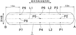
- the temperature of the aluminum material is controlled immediately before any one of the one or plural passes excluding the first pass and the final pass. Specifically, immediately before any of the passes, as shown in FIG. 1, the temperature of the central portion P5 in the width direction (direction perpendicular to the rolling direction) and the longitudinal direction (rolling direction) of the aluminum material 1 is set to 400 ° C. Assuming that the timing of 500 ° C. or less is the temperature management timing, control is performed so that the temperature difference of the entire aluminum material 1 at this temperature management timing is 40 ° C. or less.
- L1 shown in FIG. 1 is an imaginary line drawn along the longitudinal direction at the center in the width direction of the aluminum material 1.
- the recrystallized grains of aluminum can be generated uniformly and finely by the pass immediately after the timing, and the ⁇ 100 ⁇ area ratio of the aluminum material for electrolytic capacitor electrodes finally obtained through the subsequent process is high and uniform. Because it can be done.
- the temperature of the center part P5 in the width direction and the longitudinal direction of the aluminum material 1 at the temperature management timing is set to 400 ° C. or more and 500 ° C. or less. More preferably, it is 420 degreeC or more and 480 degrees C or less.
- the passes other than the first pass and the final pass of hot rolling when there are a plurality of passes in which the temperature of the center part in the width direction and the longitudinal direction of the aluminum material is 400 ° C. or more and 500 ° C. or less immediately before the pass.
- the average value of the temperature in the center in the width direction and the longitudinal direction of the aluminum material is 450 ° C. immediately before the pass, or immediately before the pass closest to 450 ° C. is set as the temperature management timing.
- the width direction and the longitudinal direction of the aluminum material immediately before rolling of the pass of the width direction and the longitudinal direction of the aluminum material immediately before the pass are twice that the temperature is 400 ° C. or more and 500 ° C. or less.
- the temperature management timing is set before the second pass among the two passes.
- the center portion in the width direction and the longitudinal direction of the aluminum material immediately before rolling has a temperature of 400 ° C. or more and 500 ° C. or less in the center portion in the width direction and the longitudinal direction at least three times. If there are multiple passes where the temperature difference between the average temperature of the steel and the 450 ° C. is the smallest, the temperature difference between the average value of the center of the width direction and the longitudinal direction of the aluminum material immediately before rolling and the 450 ° C. Among the multiple passes having the smallest value, the temperature management timing is set immediately before the last pass.
- the temperature difference in the entire aluminum material 1 at the temperature control timing is set to 40 ° C. or less because if the temperature difference exceeds 40 ° C., the crystal grains are not uniform in the entire aluminum material 1 as a result. 100 ⁇ Variation in area ratio increases. The characteristics required for aluminum materials for electrolytic capacitor electrodes are severe, and this variation is not acceptable. More preferably, the temperature difference of the entire aluminum material 1 is 30 ° C. or less.
- the temperature difference in the whole is obtained by actually measuring the temperature of a predetermined part of the aluminum material 1.
- the width of the aluminum material 1 for each of the three parts 1.5 m inside from the front end A and rear end B in the longitudinal direction and the central part in the longitudinal direction, of the aluminum material 1.
- the temperature is measured at a total of nine points P1 to P9, ie, three parts, 15% inside the entire width and the center part in the width direction from both ends in the direction.
- L2 shown in FIG. 1 is two imaginary lines drawn along the longitudinal direction from both ends in the width direction of the aluminum material 1 to an inner portion of 15% of the entire width.
- the tip A is a part that is rolled first in the pass immediately after the temperature management timing
- the rear end B is a part that is rolled last in the pass immediately after the temperature management timing.
- the difference between the highest value and the lowest value among the temperatures measured at 9 locations P1 to P9 is defined as the temperature difference of the aluminum material 1 as a whole.
- Examples of the method for measuring the temperature of the aluminum material 1 include a method of measuring using thermography, a method of measuring the aluminum material 1 using a contact-type thermometer after stopping the aluminum material 1 between the passes.
- the temperature of the aluminum material 1 was controlled after the aluminum material 1 was separated from the work roll of the hot rolling mill, and then the temperature of the aluminum material 1 may be measured and then rolled, or rolled in a pass immediately before the soot temperature control timing.
- rolling in a pass immediately after the temperature management timing may be sequentially performed from a part where temperature control such as cooling is performed and the temperature is measured.
- Examples of a method for controlling the temperature of the center part P5 in the width direction and the longitudinal direction of the aluminum material 1 to 400 ° C. or more and 500 ° C. or less include a method of heating / cooling the aluminum material 1 and the like. Further, as a method for controlling the temperature difference in the entire aluminum material 1, for example, the aluminum material 1 is cooled immediately before the temperature management timing, and at that time, the amount of the refrigerant to be injected to the high temperature portion is set to the temperature. Examples include a method of increasing the temperature of the low temperature region, a method of decreasing the amount of the refrigerant injected to the low temperature region of the high temperature region, a method of partially heating only the low temperature region, and the like.
- a more preferable rolling reduction in the pass immediately before the temperature management timing is 40% or more and 70% or less.
- the thickness of the aluminum material is preferably 10 mm or more and 100 mm or less. If the thickness of the aluminum material is less than 10 mm, the degree of subsequent processing cannot be increased, which may cause coarse grains. When the thickness of the aluminum material exceeds 100 mm, the crystal grain refinement does not proceed, so that a high ⁇ 100 ⁇ area ratio may not be obtained. More preferably, it is good to set it as 10 mm or more and 60 mm or less.
- the width of the aluminum material at the temperature control timing is preferably 500 mm or more and 3000 mm or less, and the length is preferably 5 m or more and 30 m or less. It is preferable to determine the size of the aluminum ingot so as to have this width or length. If the width of the aluminum material at the temperature control timing is less than 500 mm or the length is less than 5 m, the amount of the aluminum material to be finally produced decreases, so that productivity may be deteriorated. If the width exceeds 3000 mm or the length exceeds 30 m, the temperature control becomes difficult, and the manufacturing cost may increase for realizing a temperature difference of 40 ° C. or less. A more preferable width of the aluminum material at the temperature control timing is 500 mm or more and 1800 mm or less, and a more preferable length is 5 m or more and 20 m or less.
- the rolling reduction is less than 25%, the rolling reduction is too low, so that recrystallization does not proceed and a high ⁇ 100 ⁇ area ratio may not be obtained. If the rolling reduction exceeds 75%, it may be difficult to control the plate crown and plate shape distortion. In addition, it is difficult to stabilize the plate surface properties due to deterioration of the lubrication conditions in the roll gap. More preferably, the rolling reduction is 45% or more and 70% or less.
- the temperature of the center part in the width direction and the longitudinal direction of the aluminum material immediately after the pass of all the hot rolling processes performed after the temperature management timing is set to be lower than the temperature of the part at the temperature management timing.
- the temperature of the aluminum material immediately after the end of the pass immediately after the temperature control timing is preferably 390 ° C. or higher and 440 ° C. or lower.
- the temperature of the aluminum material immediately after the pass immediately before the final pass of hot rolling is preferably 380 ° C. or lower. When the temperature of the aluminum material exceeds 380 ° C., a part of the crystal may be recrystallized and the structure may become non-uniform. If the temperature of the aluminum material immediately after the pass immediately before the final pass of the hot rolling is too low, the corrosion caused by moisture in the hot rolling oil or the residue of the emulsifier adheres to the aluminum surface, so that etching occurs during electrolytic etching. Surface quality abnormalities that hinder the generation and growth of pits are likely to occur. More preferably, the surface temperature of the aluminum material immediately after the pass immediately before the final pass of the hot rolling is set to 200 ° C. or more and 380 ° C. or less.
- the thickness of the aluminum material immediately before the final pass is preferably 5 mm or more and 20 mm or less. If the thickness is less than 5 mm, the rolling texture does not develop, and it may be difficult to obtain a high cocoon ⁇ 100 ⁇ heel area ratio. On the other hand, if it exceeds 20 mm, the number of passes in the cold rolling process increases, which may be disadvantageous in terms of productivity.
- the temperature of the aluminum material immediately after the end of hot rolling is preferably 300 ° C. or less. If it exceeds 300 ° C, the crystal structure may be non-uniform.
- the thickness of the aluminum material immediately after the hot rolling is 3 mm or more and 15 mm or less. If the thickness is less than 3 mm, the rolling texture does not develop, and it may be difficult to obtain a high cocoon ⁇ 100 ⁇ heel area ratio. On the other hand, if it exceeds 15 mm, the number of passes in the cold rolling process increases, which may be disadvantageous in terms of productivity.
- rolling may be performed using the same rolling mill as that used up to the final pass, or rolling may be performed using another rolling mill.
- rolling may be performed once using a rolling stand having a pair of upper and lower work rolls, or tandem rolling may be performed using a plurality of upper and lower sets of work rolls.
- it may be wound using a winding device after the final pass of hot rolling.
- cold rolling and foil rolling are performed, and final annealing is performed. If necessary, intermediate annealing may be performed during cold rolling or foil rolling. These cold rolling, foil rolling, intermediate annealing, and final annealing may be performed according to known conditions.
- the ⁇ 100 ⁇ area ratio after final annealing becomes high and uniform throughout the aluminum material, and there are no coarse grains.
- Aluminum material can be obtained.
- the thickness of the aluminum material for electrolytic capacitor electrodes obtained after the final annealing is not particularly specified. Those having a thickness of 200 ⁇ m or less, referred to as foil, and those having a thickness larger than that are also included in the present invention.
- the aluminum material that has undergone final annealing is subjected to an etching process in order to improve the surface expansion ratio.
- Etching conditions are not particularly limited, but preferably a direct current etching method is employed.
- the direct current etching method the portion that becomes the nucleus of the etch pit promoted in the annealing is deeply and thickly etched to generate a large number of tunnel-like pits, thereby realizing a high capacitance.
- anode material After the etching treatment, it is desirable to carry out a chemical conversion treatment to obtain an anode material.
- it may be used as an electrolytic capacitor electrode material for medium pressure and high pressure, but it does not preclude use as a cathode material.
- the electrolytic capacitor using this electrode material can realize a large capacitance.
- the capacitance may be measured in accordance with a conventional method. For example, a method of measuring a chemically treated etched foil at 120 Hz in an 80 g / L ammonium borate aqueous solution at 30 ° C. using a stainless steel plate as a counter electrode. It can be illustrated.
- the aluminum ingot having the composition shown in Table 1 was chamfered, subjected to soaking at 600 ° C. for 7 hours, the temperature was lowered, and hot rolling was started at the ingot temperature of 540 ° C. The condition of soaking was 600 ° C. ⁇ 7 hours.
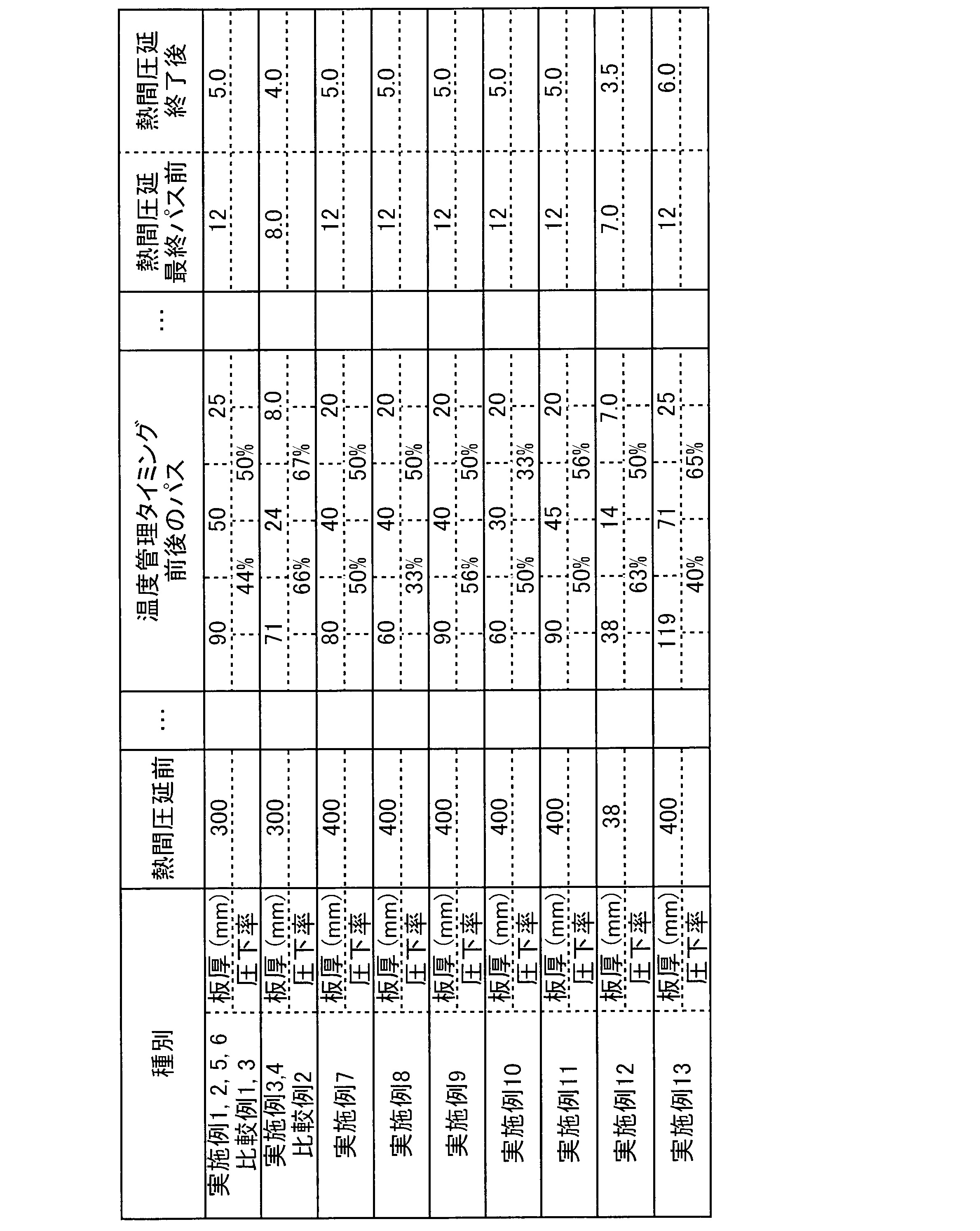
- the thickness of the aluminum material before hot rolling was as shown in Table 2.
- the cooling was terminated when the temperature of the center part in the width direction and the longitudinal direction of the aluminum material reached the temperature shown in Table 3 (temperature control timing).
- the temperature difference of the aluminum material was determined by measuring the temperature of the aluminum material using a contact thermometer. As shown in FIG. 1, the temperature measurement is performed from the both ends in the width direction of the aluminum material 1 to the full width of each of the three parts, each 1.5 m inside from the both ends in the longitudinal direction of the aluminum material 1 and the central portion in the longitudinal direction.
- the test was performed at 9 locations P1 to P9 in total, 3 locations of 15% inside and a central portion in the width direction. And the difference of the highest value and the lowest value among the obtained measurement temperature was made into the temperature difference in the whole aluminum material 1.
- a method of injecting water from above and below the horizontal aluminum material was adopted as a cooling method of the aluminum material.
- the amount of the refrigerant (water) injected into the center part in the width direction and the longitudinal direction of the aluminum material is larger than that in the other parts.
- cooling was performed so that the temperature difference in the entire aluminum material was 40 ° C. or less.
- Examples 7 to 12 by reducing the amount of refrigerant injected to the front end portion, rear end portion and rolling end portion (width direction end portion) in the length direction of the aluminum material relative to the center portion.
- the aluminum material was cooled so that the temperature difference in the entire aluminum material was 40 ° C. or less.
- cooling was performed by relatively increasing the amount of refrigerant injected to the front end portion, rear end portion, and rolling end portion (width direction end portion) in the length direction of the aluminum material from the center portion. .
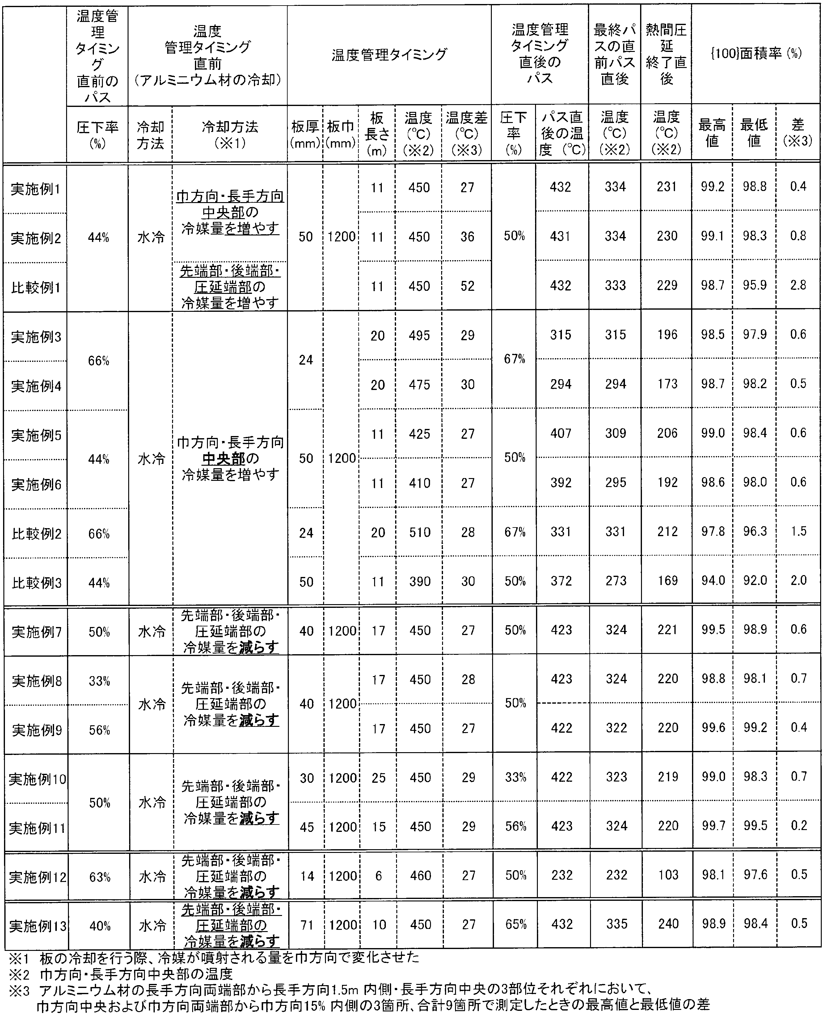
- Table 3 shows the thickness, width, length of the aluminum material at the temperature control timing, the temperature in the width direction and the central portion in the length direction, and the overall temperature difference.
- Table 2 shows the thickness of the aluminum material before and after the pass before and after the temperature control timing, the reduction ratio of these passes, the thickness of the aluminum material immediately before the final pass, and the thickness of the aluminum material after the hot rolling is finished. It was as shown in.
- Example 2 and Comparative Example 3 the pass in which the temperature of the aluminum material immediately before rolling was 400 ° C. or more and 500 ° C. or less in rough hot rolling was not performed.
- the temperature immediately before the pass at which the temperature of the aluminum material was closest to 400 ° C. or more and 500 ° C. or less was defined as the temperature control timing.
- Example 4 and Comparative Example 2 the pass of the hot rolling process was performed twice after the temperature control timing. Further, in Example 1, Example 2, Examples 5 to 13, Comparative Example 1 and Comparative Example 3, the pass of the hot rolling process was performed three times after the temperature control timing.
- the hot rolling, cold rolling, intermediate annealing, and foil rolling were sequentially performed to obtain a final thickness foil, and final annealing was performed to obtain an aluminum material for electrolytic capacitor electrodes.
- the intermediate annealing was performed at 250 ° C. for 24 hours, and the final annealing was performed at 500 ° C. for 6 hours, both in a nitrogen gas atmosphere.
- the ⁇ 100 ⁇ area ratio of the aluminum material obtained by the above manufacturing method was measured.
- a treatment liquid in which 35% HCl: 60% HNO 3: 48% HF was mixed at a volume ratio of 75: 25: 1 was used. This processing liquid is maintained at 30 ° C., and after immersing the aluminum material for 30 seconds, washing with water and drying change the gloss of the ⁇ 100 ⁇ -oriented crystal grains and the crystal grains on the other side, and perform image processing.
- the ⁇ 100 ⁇ area ratio was measured.
- Example 1 Example 2 and Comparative Example 1
- Example 2 and Comparative Example 1 the cooling conditions of the aluminum material in the hot rolling process are different, and the other process conditions are manufactured under the same conditions.
- the temperature difference was 27 ° C. in Example 1, 36 ° C. in Example 2, and 52 ° C. in Comparative Example 1.
- Example 1 From the comparison of Example 1, Example 2 and Comparative Example 1, at the temperature control timing of the hot rolling process, the amount of refrigerant injected into the center part in the width direction and the longitudinal direction of the aluminum material is relatively increased. It was confirmed that by suppressing the overall temperature difference, a uniform aluminum material for electrolytic capacitor electrodes with a high ⁇ 100 ⁇ area ratio was obtained.
- Example 3 Comparative Example 2 and Comparative Example 3
- the ⁇ 100 ⁇ area ratio is low when the temperature of the center part in the width direction and the longitudinal direction of the aluminum material at the temperature control timing is less than 400 ° C or more than 500 ° C.
- the ⁇ 100 ⁇ area ratio shows a higher value when the temperature of the center part in the width direction and the longitudinal direction of the aluminum material at the temperature control timing is 420 ° C. or higher and 480 ° C. or lower.
- Comparative Example 2 and Comparative Example 3 By using Examples 3 to 6, Comparative Example 2 and Comparative Example 3 to set the temperature of the aluminum material at the temperature control timing to 400 ° C. or more and 500 ° C. or less, more preferably 420 ° C. or more and 480 ° C. or less, the ⁇ 100 ⁇ area ratio It was confirmed that a high aluminum material was obtained.
- Example 7 to 9 In Examples 7 to 9, the rolling reduction in the pass immediately before the temperature control timing in the hot rolling process is different. From Table 3, it can be seen that the value of ⁇ 100 ⁇ area ratio increases as the rolling reduction in the pass immediately before the temperature management timing increases.
- Example 7, Example 10 and Example 11 differ in the rolling reduction in the pass immediately after the temperature control timing of the hot rolling process. From Table 3, it can be seen that the value of ⁇ 100 ⁇ area ratio increases as the rolling reduction in the pass immediately after the temperature control timing increases.
- Example 7 Example 10, and Example 11, it was confirmed that an aluminum material having a higher ⁇ 100 ⁇ % area ratio can be obtained by increasing the rolling reduction in the pass immediately after the temperature control timing.
- Example 12 and Example 13 In Example 12 and Example 13, when the aluminum material was cooled in the hot rolling process, the amount of refrigerant injected into the front end portion, the rear end portion, and the rolling end portion in the longitudinal direction of the aluminum material was relatively reduced. Is.
- the temperature difference of the aluminum material at the temperature control timing is 27 ° C., the ⁇ 100 ⁇ area ratio is high, and the variation is small.
- Example 12 when the aluminum material is cooled, ⁇ 100 ⁇ area ratio is uniform and high by relatively reducing the amount of refrigerant injected to the front end, rear end, and rolling end. It was confirmed that an aluminum material was obtained.
- the present invention can be used for the production of aluminum materials for electrolytic capacitor electrodes, the production of electrode materials for aluminum electrolytic capacitors, and the production of aluminum electrolytic capacitors.
Landscapes
- Chemical & Material Sciences (AREA)
- Engineering & Computer Science (AREA)
- Mechanical Engineering (AREA)
- Power Engineering (AREA)
- Materials Engineering (AREA)
- Metallurgy (AREA)
- Organic Chemistry (AREA)
- Thermal Sciences (AREA)
- Crystallography & Structural Chemistry (AREA)
- Physics & Mathematics (AREA)
- Microelectronics & Electronic Packaging (AREA)
- Chemical Kinetics & Catalysis (AREA)
- Electrochemistry (AREA)
- Metal Rolling (AREA)
Abstract
結晶粒を微細かつ均一にすることができ、高い{100}面積率を有してエッチング特性に優れた高静電容量の電解コンデンサ電極用アルミニウム材を製造する。 アルミニウム鋳瑰に少なくとも実施される熱間圧延工程が最初のパスと最終パスを含む3パス以上の圧延工程からなる。熱間圧延工程における最初のパスと最終パスを除くパスのうちの何れかのパスの直前において、アルミニウム材の巾方向及び長手方向の中央部の温度が400℃以上500℃以下であるタイミングを温度管理タイミングとしたときに、温度管理タイミングにおけるアルミニウム材の全体での温度差が40℃以下であり、かつ、温度管理タイミング以降に実施される全ての熱間圧延工程のパス直後のアルミニウム材の巾方向及び長手方向の中央部の温度を温度管理タイミングにおける当該部の温度未満とする。
Description
この発明は、電解コンデンサ電極用アルミニウム材の製造方法、アルミニウム電解コンデンサ用電極材の製造方法、およびアルミニウム電解コンデンサの製造方法に関する。
なお、この明細書において「アルミニウム」の語はその合金を含む意味で用いる。
アルミニウム電解コンデンサ電極用として一般に用いられるアルミニウム材には、その実効面積を拡大して単位面積当たりの静電容量を増大させるために、エッチング処理が施される。特に高い静電容量が求められる場合においては、エッチング処理方法として直流エッチングを選択する場合が多い。このとき、立方体方位粒の占有率(以下、{100}面積率ともいう)が低い場合、エッチングによる拡面処理の効果を十分に得ることができない。すなわち、高静電容量を得るためには、{100}面積率がアルミニウム材の部位によらず高く均一であるアルミニウム材が必要となる。
このようなアルミニウム材を得るため、例えば特許文献1、特許文献2には、熱間圧延工程により得られるアルミニウム材の板厚や圧下率を制御することで、熱間圧延工程における結晶粒を微細化する技術が開示されている。また特許文献3には、熱間圧延工程における温度条件を制御することで、熱間圧延工程における結晶粒を微細化する技術が開示されている。さらに特許文献4には、熱間圧延の開始温度を規定したり、熱間圧延におけるワークロールにブラシロールを接触させる技術が開示されている。
しかしながら、特許文献1、2に記載されているような熱間圧延における圧下率・板厚を制御する技術や、特許文献3に記載されているような熱間圧延工程における温度条件を制御する技術を適用しても、高い{100}面積率を得ることができないか、もしくはアルミニウム材の部位によって{100}面積率のバラツキが大きいという問題があった。
このような問題が発生する原因の一つとして、熱間圧延工程におけるアルミニウム材の温度が部位によってバラツキが大きいことが考えられ、また、このような温度バラツキが発生する要因としては、熱延板搬送用のローラーとの接触部近傍で局部的に温度が低下しやすくなることが考えられる。しかしながら、従来の電解コンデンサ電極用アルミニウム材の製造方法において、熱間圧延工程におけるアルミニウム材の温度バラツキに着目してこれを抑制することは検討されていなかった。
また、特許文献4に記載の技術は、熱間圧延開始温度が比較的低温であるため、得られる電解コンデンサ電極用アルミニウム材のエッチング特性の制御に制約があった。
この発明は、このような実情に鑑みてなされたものであり、結晶粒を微細かつ均一にすることができ、高い{100}面積率を有してエッチング特性に優れた高静電容量の電解コンデンサ電極用アルミニウム材を製造することができる電解コンデンサ電極用アルミニウム材の製造方法を提供し、さらには電解コンデンサ電極用アルミニウム材、電解コンデンサ用電極材及びアルミニウム電解コンデンサを提供することを課題とする。
本発明のその他の目的及び利点は、以下の好ましい実施形態から明らかであろう。
本発明のその他の目的及び利点は、以下の好ましい実施形態から明らかであろう。
上記の課題を解決するために、発明者らは鋭意研究の結果、熱間圧延工程におけるアルミニウム材の温度制御を厳密に行うことにより、熱間圧延上がりの結晶粒を微細均一にでき、{100}面積率の高いアルミニウム材を得ることができることを見出して、本発明の完成に至った。
すなわち、本発明の電解コンデンサ電極用アルミニウム材の製造方法および電解コンデンサ電極材の製造方法は、下記の構成を有する。
(1)アルミニウム鋳瑰に少なくとも熱間圧延工程を実施して電解コンデンサ電極用アルミニウム材を製造するに際し、前記熱間圧延工程が最初のパスと最終パスを含む3パス以上の圧延工程からなり、前記最初のパスと最終パスを除くパスのうちパスの直前において、アルミニウム材の巾方向及び長手方向の中央部の温度が400℃以上500℃以下であるタイミングを温度管理タイミングとしたときに、前記温度管理タイミングにおけるアルミニウム材の全体での温度差が40℃以下であり、かつ、前記温度管理タイミング以降に実施される全ての熱間圧延工程のパス直後のアルミニウム材の巾方向及び長手方向の中央部の温度を温度管理タイミングにおける当該部の温度未満とすることを特徴とする電解コンデンサ電極用アルミニウム材の製造方法。
(2)前記アルミニウム材の全体の温度差は、前記アルミニウム材の長手方向の両端から1.5m内側の部位と長手方向の中央部の3部位それぞれについて、アルミニウム材の巾方向の両端から全巾の15%内側の部位と巾方向中央部の3箇所の合計9箇所で温度を測定したときの最高温度と最低温度の差で定義される前項1に記載の電解コンデンサ電極用アルミニウム材の製造方法。
(3)前記温度管理タイミングにおけるアルミニウム材の巾方向及び長手方向の中央部の温度が420℃以上480℃以下である前項1または前項2に記載の電解コンデンサ電極用アルミニウム材の製造方法。
(4)前記温度管理タイミングにおけるアルミニウム材の全体での温度差が30℃以下である前項1ないし前項3のいずれか1項に記載の電解コンデンサ電極用アルミニウム材の製造方法。
(5)前記温度管理タイミングにおけるアルミニウム材の厚さが10mm以上100mm以下である前項1ないし前項4のいずれか1項に記載の電解コンデンサ電極用アルミニウム材の製造方法。
(6)前記温度管理タイミングにおけるアルミニウム材の巾が500mm以上3000mm以下であって、かつアルミニウム材の長さが5m以上30m以下である前項1ないし前項5のいずれか1項に記載の電解コンデンサ電極用アルミニウム材の製造方法。
(7)前記温度管理タイミングの直後のパスにおける圧下率が25%以上75%以下である前項1ないし前項6のいずれか1項に記載の電解コンデンサ電極用アルミニウム材の製造方法。
(8)前記圧下率が45%以上70%以下である前項7に記載の電解コンデンサ電極用アルミニウム材の製造方法。
(9)前記温度管理タイミングの直前のパスにおける圧下率が25%以上75%以下である前項1ないし前項8のいずれか1項に記載の電解コンデンサ電極用アルミニウム材の製造方法。
(10)前記圧下率が40%以上70%以下である前項9に記載の電解コンデンサ電極用アルミニウム材の製造方法。
(11)前記温度管理タイミングの直後のパスの終了直後のアルミニウム材の温度が390℃以上440℃以下である前項1ないし前項10のいずれか1項に記載の電解コンデンサ電極用アルミニウム材の製造方法。
(12)前記最初のパスの直前のアルミニウム材の温度が460℃以上580℃以下であって、かつ、前記最終パス直前のパスを施した直後のアルミニウム材の温度が380℃以下であり、さらに前記熱間圧延の終了直後のアルミニウム材の温度が300℃以下である前項1ないし前項11のいずれか1項に記載の電解コンデンサ電極用アルミニウム材の製造方法。
(13)前記最終パスの直前のアルミニウム材の厚さが5mm以上20mm以下であって、かつ前記熱間圧延の終了後のアルミニウム材の厚さが3mm以上15mm以下である前項1ないし前項12のいずれか1項に記載の電解コンデンサ電極用アルミニウム材の製造方法。
(14)前記アルミニウム材のアルミニウム純度が99.9質量%以上である前項1ないし前項13のいずれか1項に記載の電解コンデンサ電極用アルミニウム材の製造方法。
(15)最終焼鈍を実施する前項1ないし前項14のいずれか1項に記載の電解コンデンサ電極用アルミニウム材の製造方法。
(16)前項1ないし前項15のいずれか1項に記載の電解コンデンサ電極用アルミニウム材の製造方法により得られた電解コンデンサ電極用アルミニウム材にさらにエッチングを施すことを特徴とするアルミニウム電解コンデンサ用電極材の製造方法。
(17)前記エッチングの少なくとも一部が直流エッチングである前項16に記載のアルミニウム電解コンデンサ用電極材の製造方法。
(18)前記エッチング終了後さらに化成処理を実施する前項16または前項17に記載のアルミニウム電解コンデンサ用電極材の製造方法。
(19)前項16ないし前項18のいずれか1項に記載のアルミニウム電解コンデンサ用電極材の製造方法により得られたアルミニウム電解コンデンサ用電極材を用いることを特徴とするアルミニウム電解コンデンサの製造方法。
(1)アルミニウム鋳瑰に少なくとも熱間圧延工程を実施して電解コンデンサ電極用アルミニウム材を製造するに際し、前記熱間圧延工程が最初のパスと最終パスを含む3パス以上の圧延工程からなり、前記最初のパスと最終パスを除くパスのうちパスの直前において、アルミニウム材の巾方向及び長手方向の中央部の温度が400℃以上500℃以下であるタイミングを温度管理タイミングとしたときに、前記温度管理タイミングにおけるアルミニウム材の全体での温度差が40℃以下であり、かつ、前記温度管理タイミング以降に実施される全ての熱間圧延工程のパス直後のアルミニウム材の巾方向及び長手方向の中央部の温度を温度管理タイミングにおける当該部の温度未満とすることを特徴とする電解コンデンサ電極用アルミニウム材の製造方法。
(2)前記アルミニウム材の全体の温度差は、前記アルミニウム材の長手方向の両端から1.5m内側の部位と長手方向の中央部の3部位それぞれについて、アルミニウム材の巾方向の両端から全巾の15%内側の部位と巾方向中央部の3箇所の合計9箇所で温度を測定したときの最高温度と最低温度の差で定義される前項1に記載の電解コンデンサ電極用アルミニウム材の製造方法。
(3)前記温度管理タイミングにおけるアルミニウム材の巾方向及び長手方向の中央部の温度が420℃以上480℃以下である前項1または前項2に記載の電解コンデンサ電極用アルミニウム材の製造方法。
(4)前記温度管理タイミングにおけるアルミニウム材の全体での温度差が30℃以下である前項1ないし前項3のいずれか1項に記載の電解コンデンサ電極用アルミニウム材の製造方法。
(5)前記温度管理タイミングにおけるアルミニウム材の厚さが10mm以上100mm以下である前項1ないし前項4のいずれか1項に記載の電解コンデンサ電極用アルミニウム材の製造方法。
(6)前記温度管理タイミングにおけるアルミニウム材の巾が500mm以上3000mm以下であって、かつアルミニウム材の長さが5m以上30m以下である前項1ないし前項5のいずれか1項に記載の電解コンデンサ電極用アルミニウム材の製造方法。
(7)前記温度管理タイミングの直後のパスにおける圧下率が25%以上75%以下である前項1ないし前項6のいずれか1項に記載の電解コンデンサ電極用アルミニウム材の製造方法。
(8)前記圧下率が45%以上70%以下である前項7に記載の電解コンデンサ電極用アルミニウム材の製造方法。
(9)前記温度管理タイミングの直前のパスにおける圧下率が25%以上75%以下である前項1ないし前項8のいずれか1項に記載の電解コンデンサ電極用アルミニウム材の製造方法。
(10)前記圧下率が40%以上70%以下である前項9に記載の電解コンデンサ電極用アルミニウム材の製造方法。
(11)前記温度管理タイミングの直後のパスの終了直後のアルミニウム材の温度が390℃以上440℃以下である前項1ないし前項10のいずれか1項に記載の電解コンデンサ電極用アルミニウム材の製造方法。
(12)前記最初のパスの直前のアルミニウム材の温度が460℃以上580℃以下であって、かつ、前記最終パス直前のパスを施した直後のアルミニウム材の温度が380℃以下であり、さらに前記熱間圧延の終了直後のアルミニウム材の温度が300℃以下である前項1ないし前項11のいずれか1項に記載の電解コンデンサ電極用アルミニウム材の製造方法。
(13)前記最終パスの直前のアルミニウム材の厚さが5mm以上20mm以下であって、かつ前記熱間圧延の終了後のアルミニウム材の厚さが3mm以上15mm以下である前項1ないし前項12のいずれか1項に記載の電解コンデンサ電極用アルミニウム材の製造方法。
(14)前記アルミニウム材のアルミニウム純度が99.9質量%以上である前項1ないし前項13のいずれか1項に記載の電解コンデンサ電極用アルミニウム材の製造方法。
(15)最終焼鈍を実施する前項1ないし前項14のいずれか1項に記載の電解コンデンサ電極用アルミニウム材の製造方法。
(16)前項1ないし前項15のいずれか1項に記載の電解コンデンサ電極用アルミニウム材の製造方法により得られた電解コンデンサ電極用アルミニウム材にさらにエッチングを施すことを特徴とするアルミニウム電解コンデンサ用電極材の製造方法。
(17)前記エッチングの少なくとも一部が直流エッチングである前項16に記載のアルミニウム電解コンデンサ用電極材の製造方法。
(18)前記エッチング終了後さらに化成処理を実施する前項16または前項17に記載のアルミニウム電解コンデンサ用電極材の製造方法。
(19)前項16ないし前項18のいずれか1項に記載のアルミニウム電解コンデンサ用電極材の製造方法により得られたアルミニウム電解コンデンサ用電極材を用いることを特徴とするアルミニウム電解コンデンサの製造方法。
前項(1)に記載の発明によれば、熱間圧延工程が最初のパスと最終パスを含む3パス以上の圧延工程からなり、最初のパスと最終パスを除くパスのうちパスの直前において、アルミニウム材の巾方向及び長手方向の中央部の温度が400℃以上500℃以下であるタイミングを温度管理タイミングとしたときに、温度管理タイミングにおけるアルミニウム材の全体での温度差が40℃以下であり、かつ、温度管理タイミング以降に実施される全ての熱間圧延工程のパス直後のアルミニウム材の巾方向及び長手方向の中央部の温度を温度管理タイミングにおける当該部の温度未満とするから、結晶粒を微細かつ均一にすることができ、高い{100}面積率を有してエッチング特性に優れひいては静電容量の大きな電解コンデンサ電極用アルミニウム材を製造することができる。
前項(2)に記載の発明によれば、温度管理タイミングにおけるアルミニウム材の全体の温度差を確実にかつ効率的に把握することができる。
前項(3)に記載の発明によれば、温度管理タイミングにおけるアルミニウム材の巾方向及び長手方向の中央部の温度が420℃以上480℃以下であるから、より高い{100}面積率を有してエッチング特性に一層優れた電解コンデンサ電極用アルミニウム材を製造することができる。
前項(4)に記載の発明によれば、温度管理タイミングにおけるアルミニウム材の全体での温度差が30℃以下であるから、より高い{100}面積率を有してエッチング特性に一層優れた電解コンデンサ電極用アルミニウム材を製造することができる。
前項(5)に記載の発明によれば、温度管理タイミングにおけるアルミニウム材の厚さが10mm以上100mm以下であるから、高い{100}面積率と結晶粒の微細化効果を確実に実現することができる。
前項(6)に記載の発明によれば、温度管理タイミングにおけるアルミニウム材の巾が500mm以上3000mm以下であって、かつアルミニウム材の長さが5m以上30m以下であるから、生産性の悪化を防止しつつアルミニウム材の温度制御を容易に行うことができる。
前項(7)に記載の発明によれば、温度管理タイミングの直後のパスにおける圧下率が25%以上75%以下であるから、圧下率が低すぎることによる再結晶が進行しないという不都合や、圧下率が大きすぎることによるアルミニウム材の巾方向での厚さの差が大きくなるという不都合を防止でき、高い{100}面積率を安定して得ることができる。
前項(8)に記載の発明によれば、温度管理タイミングの直後のパスにおける圧下率が45%以上70%以下であるから、高い{100}面積率をさらに安定して得ることができる。
前項(9)に記載の発明によれば、温度管理タイミングの直前のパスにおける圧下率が25%以上75%以下であるから、圧下率が低すぎることによるアルミニウム圧延組織の均質化が不十分という不都合や、圧下率が大きすぎることによるアルミニウム材の巾方向での厚さの差が大きくなるという不都合を防止でき、高い{100}面積率を安定して得ることができる。
前項(10)に記載の発明によれば、温度管理タイミングの直後のパスにおける圧下率が40%以上70%以下であるから、高い{100}面積率をさらに安定して得ることができる。
前項(11)に記載の発明によれば、温度管理タイミングの直後のパスの終了直後のアルミニウム材の温度が390℃以上440℃以下であるので、結晶粒の微細化を安定して実現できる。
前項(12)に記載の発明によれば、アルミニウム材の温度が高すぎることによる結晶組織が不均一となるという不都合を防止でき、高い{100}面積率を安定して得ることができる。
前項(13)に記載の発明によれば、パス数が多くなることによる生産性の低下を防止しつつ、圧延集合組織の発達による高い{100}面積率を得ることができる。
前項(14)に記載の発明によれば、アルミニウム材のアルミニウム純度が99.9質量%以上であるから、アルミニウム材中の不純物の量を少なくでき、{100}面積率の高い電解コンデンサ用アルミニウム材を製造できる。
前項(15)に記載の発明によれば、最終焼鈍により再結晶を促進して高い{100}面積率を有する電解コンデンサ電極用アルミニウム材を製造できる。
前項(16)に記載の発明によれば、エッチングにより大きな静電容量を有する電解コンデンサ電解コンデンサ用電極材を製造することができる。
前項(17)に記載の発明によれば、エッチングの少なくとも一部が直流エッチングにより行われるから、深くて太い多数のトンネル状ピットが生成された、大きな静電容量を有する電解コンデンサ用電極材を製造することができる。
前項(18)に記載の発明によれば、さらに化成処理が施されているから、陽極材として好適な電解コンデンサ用電極材を製造することができる。
前項(19)に記載の発明によれば、高静電容量のアルミニウム電解コンデンサを製造することができる。
本実施形態に係る電解コンデンサ用アルミニウム材の製造方法に用いるアルミニウム材の組成は、限定はされないが、アルミニウム純度が 99.9質量%以上であるのが望ましい。ここでアルミニウム純度は{100質量%-(Si濃度(質量%)+Fe濃度(質量%)+Cu濃度(質量%))}とする。アルミニウム材のアルミニウム純度が99.9質量%未満であると不純物の量が多すぎるため、{100}面積率の高いアルミニウム材を得ることが容易でなくなる恐れがある。より好ましくはアルミニウム純度が99.99質量%以上のものを用いるのが良い。
電解コンデンサ用アルミニウム材の製造は、一般的には、アルミニウム鋳塊の鋳造、面削、均質化熱処理、鋳瑰の加熱、熱間圧延、冷間圧延、箔圧延、最終焼鈍の各工程の順次的実施により行われる。ここで、面削と均質化熱処理の順序は逆であっても良く、均質化熱処理と鋳瑰の加熱は連続実施であってもなくても良い。また、必要に応じて冷間圧延・箔圧延の途中に中間焼鈍を行っても良い。鋳塊の鋳造、面削、均質化熱処理、鋳瑰の加熱、冷間圧延、箔圧延、中間焼鈍、最終焼鈍は公知の条件に従って行えばよい。
本実施形態において、鋳瑰の加熱後にアルミニウム鋳瑰に実施する熱間圧延工程は、最初のパスと最終パスを含む3パス以上の圧延工程からなるが、熱間圧延の開始時、すなわち最初のパスを行う直前におけるアルミニウム鋳瑰の温度は460℃以上580℃以下とするのが好ましい。アルミニウム鋳瑰の温度が460℃未満であると、Al-Feあるいは Al-Fe-Si系の微細析出物がマトリックス内に析出し、最終焼鈍後もこの微細析出物が再固溶することなく残るため、エッチング時に局部溶解を起こし、高静電容量を得ることができない恐れがある。一方、アルミニウム鋳瑰の温度が580℃を超えると、熱間圧延初期の再結晶粒径が粗大化するため、熱間圧延上がりの結晶粒径を微細化することができず、高い{100}面積率を得ることが困難になる場合がある。従って、熱間圧延工程における最初のパスを行う直前におけるアルミニウム鋳瑰の温度は460℃以上580℃以下とするのが良い。
熱間圧延工程における最初のパスと最終パスを除く1個または複数個のパスのうち、何れかのパスの直前においてアルミニウム材の温度制御を行う。具体的には、何れかのパスの直前において、図1に示すように、アルミニウム材1の巾方向(圧延方向と直角な方向)及び長手方向(圧延方向)の中央部P5の温度を400℃ 以上500℃以下としたタイミングを温度管理タイミングとすると、この温度管理タイミングにおけるアルミニウム材1の全体での温度差が40℃以下となるように制御する。図1に示すL1は、アルミニウム材1の巾方向の中央部において長手方向に沿って引いた仮想線である。
温度管理タイミングにおけるアルミニウム材1の巾方向及び長手方向の中央部P5の温度を400℃ 以上500℃以下に規定したのは、当該温度範囲のアルミニウム材1の温度差を小さくすることによって、温度管理タイミングの直後のパスによってアルミニウムの再結晶粒を均一かつ微細に発生させることができ、その後の工程を経て最終的に得られる電解コンデンサ電極用アルミニウム材の{100}面積率を高く均一なものとすることができるからである。
具体的には、温度管理タイミングにおけるアルミニウム材1の巾方向及び長手方向の中央部P5の温度が400℃未満であると、温度が低すぎるため、直後のパス後に再結晶が進行せず、全体の温度差を小さくしても{100}面積率の改善効果が得られない。また、温度が500℃を超えると、全体の温度差を小さくしても、直後のパスの実施後に生成する結晶粒が大きくなり、熱間圧延後のアルミニウム材の結晶粒を微細化させる効果は小さく、やはり{100}面積率の改善効果が得られない。従って、温度管理タイミングにおけるアルミニウム材1の巾方向及び長手方向の中央部P5の温度は400℃以上500℃以下とする。より好ましくは420℃以上480℃以下である。
熱間圧延の最初のパスと最終パスを除くパスのうち、パスの直前においてアルミニウム材の巾方向及び長手方向の中央部の温度が400℃以上500℃以下となるパスが複数回存在するときは、パスの直前においてアルミニウム材の巾方向及び長手方向の中央部の温度の平均値が450℃であるか、もしくは450℃に最も近いパスの直前を温度管理タイミングとする。
なお、パス直前のアルミニウム材の巾方向及び長手方向の中央部の温度が400℃以上500℃以下であるパスが2回であって2回のパスの圧延直前のアルミニウム材の巾方向及び長手方向の中央部の温度の平均値と450℃との温度差が等しい場合は、上記2回のパスのうち2回目のパス前を温度管理タイミングとする。さらに、圧延直前のアルミニウム材の巾方向及び長手方向の中央部の温度が400℃以上500℃以下であるパスが3回以上であって、パス直前のアルミニウム材の巾方向及び長手方向の中央部の温度の平均値と450℃との温度差が最も小さいパスが複数回存在する場合は、圧延直前のアルミニウム材の巾方向及び長手方向の中央部の温度の平均値と450℃との温度差が最も小さい複数回のパスのうち、最後に実施するパス直前を温度管理タイミングとする。
温度管理タイミングにおけるアルミニウム材1の全体での温度差を40℃以下とするのは、温度差が40℃を超えると、結晶粒の状態がアルミニウム材1の全体で均一にならず、結果として{100}面積率のバラツキが大きくなる。電解コンデンサ電極用アルミニウム材に求められる特性は厳しく、このバラツキは許容されるものではない。より好ましくは、アルミニウム材1の全体の温度差は30℃以下とするのが良い。
一方、温度管理タイミングにおけるアルミニウム材1の全体での温度差を完全に0にすることは困難である。熱間圧延工程において、アルミニウム材1は搬送用のローラーで搬送され、搬送用のローラーとの接触部近傍で局部的に温度が低下しやすくなるが、このような温度低下要因を完全に排除することが困難である。このような状況下で温度差を完全に0にするためには、例えば、アルミニウム材1の温度分布を常に測定し続け、測定データをもとに端部等を局部的に加熱するといった高度な温度制御が必要となり、製造コストが高くなる。このため、アルミニウム材1の全体での温度差は0℃でなくても良い。
この実施形態では、アルミニウム材1の所定の部位の温度を実際に測定することにより、全体での温度差を求めている。具体的には、図1に示すように、アルミニウム材1の長手方向の先端A及び後端Bから各1.5m内側の部位と長手方向の中央部の3部位それぞれについて、アルミニウム材1の巾方向の両端から全巾の15%内側の部位と巾方向中央部との3箇所の合計9箇所P1~P9で温度を測定する。なお、図1に示すL2はアルミニウム材1の巾方向の両端部から全巾の15%だけ内側の部分に長手方向に沿って引いた2本の仮想線である。
ここで、先端Aは温度管理タイミングの直後のパスにおいて最初に圧延される部位であり、後端Bは温度管理タイミングの直後のパスにおいて最後に圧延される部位である。
そして、9箇所P1~P9で測定した温度の中の最高値と最低値の差を、アルミニウム材1の全体での温度差としている。このような方法によりアルミニウム材1の全体の温度差を求めることにより、温度管理タイミングにおけるアルミニウム材1の全体での温度差を簡易な方法で確実にかつ効率的に把握することができる。温度測定点をさらに増やしても良いことは勿論である。
アルミニウム材1の温度測定方法としては、例えば、サーモグラフィーを用いて測定する方法、パスとパスの間でアルミニウム材1を静止させ、接触式温度計を用いて測定する方法等などが挙げられる。アルミニウム材1を熱間圧延機のワークロールから離間した状態で温度制御を行った後アルミニウム材1の温度を測定し、次いで圧延しても良いし、 温度管理タイミングの直前のパスにおいて圧延された部位から順次冷却等温度制御を行った後、アルミニウム材1の温度を測定しても良い。また、冷却等温度制御を行い温度を測定した部位から順次温度管理タイミング直後のパスにおける圧延を実施しても良い。
アルミニウム材1の巾方向及び長手方向の中央部P5の温度を400℃以上500℃ 以下に制御する方法としては、例えば、アルミニウム材1を加熱・冷却する方法等が挙げられる。またアルミニウム材1の全体での温度差を制御する方法としては、例えば、温度管理タイミングの直前にアルミニウム材1の冷却を行い、かつその際に、温度の高い部位に噴射する冷媒の量を温度の低い部位よりも増大させる方法、温度の低い部位に噴射する冷媒の量を温度の高い部位よりも減少させる方法、あるいは温度の低い部位のみを部分的に加熱する方法等が挙げられる。
温度管理タイミングの直前のパスにおける圧下率は25%以上75%以下に設定するのが望ましい。圧下率が25%未満であると、圧下率が低すぎるためにアルミニウム圧延組織の均質化が不十分であり、高い{100}面積率を得ることができない恐れがある。圧下率が75%を超えると、アルミニウム材の板クラウンならびに板形状歪の制御が困難になる恐れがある。またロール間隙内の潤滑条件の悪化により板表面性状の安定化が困難になる恐れがある。温度管理タイミングの直前のパスにおけるより好ましい圧下率は40%以上70%以下である。
温度管理タイミングにおいて、アルミニウム材の厚さは10mm以上100mm以下であるのが好ましい。アルミニウム材の厚さが10mm未満の場合は、その後の加工度を大きくとれないため粗大粒が発生する原因となる恐れがある。アルミニウム材の厚さが100mmを超える場合は、結晶粒の微細化が進行しないため、高い{100}面積率を得ることができない恐れがある。より好ましくは10mm以上60mm以下とするのが良い。
また、温度管理タイミングにおけるアルミニウム材の巾は好ましくは500mm以上3000mm以下とするのが良く、また長さは好ましくは5m以上30m以下とするのが良い。この巾あるいは長さになるようにアルミニウム鋳塊の大きさを決定しておくことが好ましい。温度管理タイミングにおけるアルミニウム材の巾が500mm未満あるいは長さが5m未満であると、最終的に製造されるアルミニウム材の量が少なくなるため、生産性が悪くなる恐れがある。3000mmを超える巾あるいは30mを超える長さでは温度制御が困難になり、温度差40℃以下の実現のためには製造コストが高くなる恐れがある。温度管理タイミングにおけるアルミニウム材のより好ましい巾は500mm以上1800mm以下、より好ましい長さは5m以上20m以下である。
温度管理タイミングの直後のパスは、圧下率25%以上75%以下で行うのが望ましい。圧下率が25%未満であると、圧下率が低すぎるために再結晶が進行せず、高い{100}面積率を得ることができない恐れがある。圧下率が75%を超えると、板クラウンならびに板形状歪の制御が困難になる恐れがある。またロール間隙内の潤滑条件の悪化により板表面性状の安定化が困難になる恐れがある。より好ましくは45%以上70%以下の圧下率とするのが良い。
温度管理タイミング以降に実施される全ての熱間圧延工程のパス直後のアルミニウム材の巾方向及び長手方向の中央部の温度を温度管理タイミングにおける当該部の温度未満とする。温度管理タイミング以降に実施される熱間圧延工程のパス直後のアルミニウム材の温度を温度管理タイミング以上とするには、熱間圧延工程途中のパス前にアルミニウム材を加熱する必要があり、製造コストが高くなる上にアルミニウム結晶粒の微細化にも不利であるからである。
熱間圧延終了後のアルミニウム結晶粒をより微細なものとするために、温度管理タイミング直後のパスの終了直後のアルミニウム材の温度は390℃以上440℃以下であることが好ましい。
熱間圧延の最終パス直前のパスを施した直後のアルミニウム材の温度は380℃以下であることが好ましい。アルミニウム材の温度が380℃を超えると結晶の一部が再結晶し、組織が不均一となる恐れがある。熱間圧延の最終パス直前のパスを施した直後のアルミニウム材の温度が低すぎる場合には、熱間圧延油の水分による腐食や乳化剤の残渣がアルミニウム表面に固着することにより、電解エッチング時にエッチピット発生および成長が妨害される表面品質異常が発生し易くなる。より好ましくは熱間圧延の最終パス直前のパスを施した直後のアルミニウム材の表面温度を200℃以上380℃以下とするのが良い。
また、最終パスの直前のアルミニウム材の厚さは5mm以上20mm以下であることが好ましい。5mm未満であると、圧延集合組織が発達しないため高い {100} 面積率を得ることが困難になる恐れがある。一方20mmを超えると、冷間圧延工程のパス数が多くなるため生産性の面で不利となる恐れがある。
また、熱間圧延終了直後のアルミニウム材の温度は300℃以下であることが好ましい。300℃を超えると結晶組織が不均一となる恐れがある。
また、熱間圧延終了直後のアルミニウム材の厚さは3mm以上15mm以下であることが好ましい。3mm未満であると、圧延集合組織が発達しないため高い {100} 面積率を得ることが困難になる恐れがある。一方15mmを超えると、冷間圧延工程のパス数が多くなるため生産性の面で不利となる恐れがある。
なお、熱間圧延の最終パスにおいては、最終パスまでに使用した圧延機と同一の圧延機を用いて圧延を行っても良いし、別の圧延機を用いて圧延を行っても良い。また別の圧延機を用いる場合、上下1組のワークロールを有する圧延スタンドを用いて1回の圧延を行ってもよいし、上下複数組のワークロールを用いてタンデム圧延を行ってもよい。冷間圧延をコイルで行う場合は、熱間圧延の最終パス後に巻き取り装置を用いて巻き取ればよい。
熱間圧延終了後、冷間圧延及び箔圧延を行い、さらに最終焼鈍を実施する。必要に応じて冷間圧延・箔圧延の途中に中間焼鈍を行ってもよい。これらの冷間圧延・箔圧延・中間焼鈍・最終焼鈍は公知の条件に従って行えばよい。
以上の工程を通じて熱間圧延後の再結晶粒を微細化させることにより、最終焼鈍後の{100}面積率がアルミニウム材の全体に亘って高く均一となり、かつ、粗大粒の存在しない電解コンデンサ電極用アルミニウム材を得ることができる。
なお、最終焼鈍後に得られる電解コンデンサ電極用アルミニウム材の厚さは特に規定されない。箔と称される200μm以下のものも、それ以上の厚いものも本発明に含まれる。
最終焼鈍を経たアルミニウム材には、拡面率向上のためエッチング処理を実施する。エッチング処理条件は特に限定されないが、好ましくは直流エッチング法を採用するのが良い。直流エッチング法によって、前記焼鈍において生成が促進されたエッチピットの核となる部分において、深く太くエッチングされ、多数のトンネル状ピットが生成され、高静電容量が実現される。
エッチング処理後、望ましくは化成処理を行って陽極材とするのが良く、特に、中圧用および高圧用の電解コンデンサ電極材として用いるのが良いが、陰極材として用いることを妨げるものではない。また、この電極材を用いた電解コンデンサは大きな静電容量を実現できる。
なお、静電容量の測定は常法に従えば良く、化成処理されたエッチド箔について、例えば30℃の80g/Lのホウ酸アンモニウム水溶液中で、ステンレス板を対極として120Hzにて測定する方法を例示できる。
表1に示す組成のアルミニウム鋳塊に面削を施し、600℃×7時間の均熱加熱を実施した後温度を降下させ、鋳塊温度540℃で熱間圧延を開始した。なお、均熱加熱の条件は600℃×7時間とした。熱間圧延前のアルミニウム材の厚さは表2に示すとおりであった。
次に、温度管理タイミング直前のパスの終了後、アルミニウム材を熱間圧延機のワークロールから離間した状態で水平方向に移動させ、表3に示す条件でアルミニウム材の冷却を開始した。
アルミニウム材の巾方向及び長手方向の中央部の温度が表3に示す温度になった時点(温度管理タイミング)で冷却を終了した。冷却終了と同時に、接触式温度計を用いてアルミニウム材の温度を測定することにより、アルミニウム材の全体の温度差を求めた。温度測定は、図1に示すように、アルミニウム材1の長手方向の両端から各1.5m内側の部位と長手方向の中央部の3部位それぞれについて、アルミニウム材1の巾方向の両端から全巾の15%内側の部位と巾方向中央部との3箇所の合計9箇所P1~P9で行った。そして、得られた測定温度のうち最高値と最低値の差をアルミニウム材1の全体での温度差とした。
なお、アルミニウム材の冷却方法としては、水平状態のアルミニウム材の上下から水を噴射する方法を採用した。このとき、表3に示すように、実施例1~6及び比較例2及び3においては、アルミニウム材の巾方向及び長手方向中央部に噴射される冷媒(水)の量を他の部分よりも相対的に増加させることにより、アルミニウム材の全体での温度差が40℃以下となるように冷却を行った。実施例7~12においては、アルミニウム材の長さ方向の先端部分、後端部分及び圧延端部(巾方向端部)に噴射される冷媒の量を中央部よりも相対的に減少させることにより、アルミニウム材の全体での温度差が40℃以下となるように冷却を行った。
比較例1においては、アルミニウム材の長さ方向の先端部分、後端部分及び圧延端部(巾方向端部)に噴射される冷媒の量を中央部よりも相対的に増加させ冷却を行った。
表3に、温度管理タイミングにおけるアルミニウム材の厚さ、巾、長さ、巾方向及び長さ方向の中央部の温度、全体での温度差を示す。
温度測定終了後、各アルミニウム材にさらに熱間圧延を施した。温度管理タイミングの前後のパスの前後におけるアルミニウム材の厚さ、これらのパスの圧下率、最終パスの直前のアルミニウム材の厚さ、熱間圧延終了後のアルミニウム材の厚さは、それぞれ表2に示すとおりであった。
なお、比較例2および比較例3では、粗熱間圧延において圧延直前のアルミニウム材温度が400℃以上500℃以下であるパスを実施しなかった為、400℃以上500℃以下範囲外で圧延直前のアルミニウム材の温度が400℃以上500℃以下に最も近いパス直前を温度管理タイミングとした。実施例3,実施例4、実施例12及び比較例2では、温度管理タイミング後に熱間圧延工程のパスを2回実施した。また、実施例1、実施例2、実施例5~13、比較例1及び比較例3では、温度管理タイミング後に熱間圧延工程のパスを3回実施した。
熱間圧延終了後、冷間圧延、中間焼鈍、箔圧延を順次実施し最終厚さの箔とした後、最終焼鈍を実施して、電解コンデンサ電極用アルミニウム材を得た。なお、中間焼鈍は250℃×24時間、最終焼鈍は500℃×6時間の条件で、いずれも窒素ガス雰囲気中で実施した。
以上の製法により得られたアルミニウム材の{100}面積率を測定した。{100} 面積率の測定にあたっては、35%HCl:60%HNO3:48%HFを容積比75:25:1で混合した処理液を用いた。この処理液を30℃に保持し、アルミニウム材を30秒浸漬した後、水洗および乾燥することにより、{100}方位の結晶粒と、他方位の結晶粒の光沢を変化させて、画像処理により{100}面積率を測定した。
{100}面積率の測定は、アルミニウム材の長手方向の両端から各1.5m内側の部位と長手方向の中央部の3部位それぞれについて、アルミニウム材の巾方向の両端から全巾の15%内側の部位と巾方向中央部との3箇所の合計9箇所で行った。そして、得られた{100}面積率のうち最高値と最低値の差を求めた。その結果を表3に示す。

(実施例1、実施例2及び比較例1)
実施例1、実施例2及び比較例1は、熱間圧延工程におけるアルミニウム材の冷却条件が異なり、それ以外の工程条件は同等として製造したものであるが、温度管理タイミングにおけるアルミニウム材の全体での温度差は、実施例1では27℃、実施例2では36℃、比較例1では52℃であった。
実施例1、実施例2及び比較例1は、熱間圧延工程におけるアルミニウム材の冷却条件が異なり、それ以外の工程条件は同等として製造したものであるが、温度管理タイミングにおけるアルミニウム材の全体での温度差は、実施例1では27℃、実施例2では36℃、比較例1では52℃であった。
表3から理解されるように、アルミニウム材の温度差が小さくなるに従い、{100}面積率は高くなり、バラツキは小さくなっていることがわかる。
実施例1、実施例2及び比較例1の比較から、熱間圧延工程の温度管理タイミングにおいて、アルミニウム材の巾方向及び長手方向の中央部に噴射される冷媒の量を相対的に増加させて全体の温度差を抑制することにより、{100}面積率が高くしかも均一な電解コンデンサ電極用アルミニウム材が得られることを確認し得た。
(実施例3~6、比較例2及び比較例3)
表3から理解されるように、温度管理タイミングにおけるアルミニウム材の巾方向及び長手方向の中央部の温度が400℃未満、あるいは500℃を超える条件では、{100}面積率が低くなることがわかる。また、温度管理タイミングにおけるアルミニウム材の巾方向及び長手方向の中央部の温度が420℃以上480℃以下の条件では、{100}面積率がより高い値を示していることがわかる。
表3から理解されるように、温度管理タイミングにおけるアルミニウム材の巾方向及び長手方向の中央部の温度が400℃未満、あるいは500℃を超える条件では、{100}面積率が低くなることがわかる。また、温度管理タイミングにおけるアルミニウム材の巾方向及び長手方向の中央部の温度が420℃以上480℃以下の条件では、{100}面積率がより高い値を示していることがわかる。
実施例3~6、比較例2及び比較例3により、温度管理タイミングにおけるアルミニウム材の温度を400℃以上500℃以下、より好ましくは420℃以上480℃以下とすることにより、{100}面積率が高いアルミニウム材が得られることを確認し得た。
(実施例7~9)
実施例7~9は、熱間圧延工程の温度管理タイミングの直前のパスにおける圧下率が異なる。表3より、温度管理タイミングの直前のパスにおける圧下率が大きいほど、{100}面積率の値は高くなっていることがわかる。
実施例7~9は、熱間圧延工程の温度管理タイミングの直前のパスにおける圧下率が異なる。表3より、温度管理タイミングの直前のパスにおける圧下率が大きいほど、{100}面積率の値は高くなっていることがわかる。
実施例7~9により、温度管理タイミングの直前のパスにおける圧下率を高くすることにより、{100}面積率がより高いアルミニウム材が得られることを確認し得た。
(実施例7、実施例10及び実施例11)
実施例7、実施例10及び実施例11は、熱間圧延工程の温度管理タイミングの直後のパスにおける圧下率が異なる。表3より、温度管理タイミングの直後のパスにおける圧下率が大きいほど、{100}面積率の値は高くなっていることがわかる。
実施例7、実施例10及び実施例11は、熱間圧延工程の温度管理タイミングの直後のパスにおける圧下率が異なる。表3より、温度管理タイミングの直後のパスにおける圧下率が大きいほど、{100}面積率の値は高くなっていることがわかる。
実施例7、実施例10及び実施例11により、温度管理タイミングの直後のパスにおける圧下率を大きくすることにより、{100} 面積率がより高いアルミニウム材が得られることを確認し得た。
(実施例12及び実施例13)
実施例12及び実施例13は、熱間圧延工程におけるアルミニウム材の冷却時において、アルミニウム材の長手方向の先端部と後端部、圧延端部に噴射される冷媒の量を相対的に少なくしたものである。温度管理タイミングにおけるアルミニウム材の温度差は27℃であり、{100}面積率は高くバラつきは小さくなっている。
実施例12及び実施例13は、熱間圧延工程におけるアルミニウム材の冷却時において、アルミニウム材の長手方向の先端部と後端部、圧延端部に噴射される冷媒の量を相対的に少なくしたものである。温度管理タイミングにおけるアルミニウム材の温度差は27℃であり、{100}面積率は高くバラつきは小さくなっている。
実施例12及び実施例13により、アルミニウム材の冷却時において、先端部、後端部、圧延端部に噴射される冷媒量を相対的に少なくすることにより、{100}面積率が均一かつ高いアルミニウム材が得られることを確認し得た。
本願は、2015年7月30日付で出願された日本国特許出願の特願2015-151083号の優先権主張を伴うものであり、その開示内容は、そのまま本願の一部を構成するものである。
ここに用いられた用語及び表現は、説明のために用いられたものであって限定的に解釈するために用いられたものではなく、ここに示され且つ述べられた特徴事項の如何なる均等物をも排除するものではなく、この発明のクレームされた範囲内における各種変形をも許容するものであると認識されなければならない。
本発明は、多くの異なった形態で具現化され得るものであるが、この開示は本発明の原理の実施例を提供するものと見なされるべきであって、それら実施例は、本発明をここに記載しかつ/または図示した好ましい実施形態に限定することを意図するものではないという了解のもとで、多くの図示実施形態がここに記載されている。
本発明の図示実施形態を幾つかここに記載したが、本発明は、ここに記載した各種の好ましい実施形態に限定されるものではなく、この開示に基づいていわゆる当業者によって認識され得る、均等な要素、修正、削除、組み合わせ(例えば、各種実施形態に跨る特徴の組み合わせ)、改良及び/又は変更を有するありとあらゆる実施形態をも包含するものである。クレームの限定事項はそのクレームで用いられた用語に基づいて広く解釈されるべきであり、本明細書あるいは本願のプロセキューション中に記載された実施例に限定されるべきではなく、そのような実施例は非排他的であると解釈されるべきである。
この発明は、電解コンデンサ電極用アルミニウム材の製造、アルミニウム電解コンデンサ用電極材の製造、およびアルミニウム電解コンデンサの製造に利用することができる。
1 アルミニウム材
Claims (19)
- アルミニウム鋳瑰に少なくとも熱間圧延工程を実施して電解コンデンサ電極用アルミニウム材を製造するに際し、
前記熱間圧延工程が最初のパスと最終パスを含む3パス以上の圧延工程からなり、前記最初のパスと最終パスを除くパスのうちパスの直前において、アルミニウム材の巾方向及び長手方向の中央部の温度が400℃以上500℃以下であるタイミングを温度管理タイミングとしたときに、前記温度管理タイミングにおけるアルミニウム材の全体での温度差が40℃以下であり、
かつ、前記温度管理タイミング以降に実施される全ての熱間圧延工程のパス直後のアルミニウム材の巾方向及び長手方向の中央部の温度を温度管理タイミングにおける当該部の温度未満とすることを特徴とする電解コンデンサ電極用アルミニウム材の製造方法。 - 前記アルミニウム材の全体の温度差は、前記アルミニウム材の長手方向の両端から1.5m内側の部位と長手方向の中央部の3部位それぞれについて、アルミニウム材の巾方向の両端から全巾の15%内側の部位と巾方向中央部の3箇所の合計9箇所で温度を測定したときの最高温度と最低温度の差で定義される請求項1に記載の電解コンデンサ電極用アルミニウム材の製造方法。
- 前記温度管理タイミングにおけるアルミニウム材の巾方向及び長手方向の中央部の温度が420℃以上480℃以下である請求項1または2に記載の電解コンデンサ電極用アルミニウム材の製造方法。
- 前記温度管理タイミングにおけるアルミニウム材の全体での温度差が30℃以下である請求項1ないし3のいずれか1項に記載の電解コンデンサ電極用アルミニウム材の製造方法。
- 前記温度管理タイミングにおけるアルミニウム材の厚さが10mm以上100mm以下である請求項1ないし4のいずれか1項に記載の電解コンデンサ電極用アルミニウム材の製造方法。
- 前記温度管理タイミングにおけるアルミニウム材の巾が500mm以上3000mm以下であって、かつアルミニウム材の長さが5m以上30m以下である請求項1ないし5のいずれか1項に記載の電解コンデンサ電極用アルミニウム材の製造方法。
- 前記温度管理タイミングの直後のパスにおける圧下率が25%以上75%以下である請求項1ないし6のいずれか1項に記載の電解コンデンサ電極用アルミニウム材の製造方法。
- 前記圧下率が45%以上70%以下である請求項7に記載の電解コンデンサ電極用アルミニウム材の製造方法。
- 前記温度管理タイミングの直前のパスにおける圧下率が25%以上75%以下である請求項1ないし8のいずれか1項に記載の電解コンデンサ電極用アルミニウム材の製造方法。
- 前記圧下率が40%以上70%以下である請求項9に記載の電解コンデンサ電極用アルミニウム材の製造方法。
- 前記温度管理タイミングの直後のパスの終了直後のアルミニウム材の温度が390℃以上440℃以下である請求項1ないし10のいずれか1項に記載の電解コンデンサ電極用アルミニウム材の製造方法。
- 前記最初のパスの直前のアルミニウム材の温度が460℃以上580℃以下であって、かつ、前記最終パス直前のパスを施した直後のアルミニウム材の温度が380℃以下であり、さらに前記熱間圧延の終了直後のアルミニウム材の温度が300℃以下である請求項1ないし11のいずれか1項に記載の電解コンデンサ電極用アルミニウム材の製造方法。
- 前記最終パスの直前のアルミニウム材の厚さが5mm以上20mm以下であって、かつ前記熱間圧延の終了後のアルミニウム材の厚さが3mm以上15mm以下である請求項1ないし12のいずれか1項に記載の電解コンデンサ電極用アルミニウム材の製造方法。
- 前記アルミニウム材のアルミニウム純度が99.9質量%以上である請求項1ないし13のいずれか1項に記載の電解コンデンサ電極用アルミニウム材の製造方法。
- 最終焼鈍を実施する請求項1ないし14のいずれか1項に記載の電解コンデンサ電極用アルミニウム材の製造方法。
- 請求項1ないし請求項15のいずれか1項に記載の電解コンデンサ電極用アルミニウム材の製造方法により得られた電解コンデンサ電極用アルミニウム材にさらにエッチングを施すことを特徴とするアルミニウム電解コンデンサ用電極材の製造方法。
- エッチングの少なくとも一部が直流エッチングである請求項16に記載のアルミニウム電解コンデンサ用電極材の製造方法。
- エッチング終了後さらに化成処理を実施する請求項16または請求項17に記載のアルミニウム電解コンデンサ用電極材の製造方法。
- 請求項16ないし請求項18のいずれか1項に記載のアルミニウム電解コンデンサ用電極材の製造方法により得られたアルミニウム電解コンデンサ用電極材を用いることを特徴とするアルミニウム電解コンデンサの製造方法。
Priority Applications (2)
| Application Number | Priority Date | Filing Date | Title |
|---|---|---|---|
| CN201680042327.2A CN107847995B (zh) | 2015-07-30 | 2016-05-18 | 电解电容器电极用铝材料的制造方法、铝电解电容器用电极材料的制造方法、和铝电解电容器的制造方法 |
| JP2017531044A JP6646672B2 (ja) | 2015-07-30 | 2016-05-18 | 電解コンデンサ電極用アルミニウム材の製造方法、アルミニウム電解コンデンサ用電極材の製造方法、およびアルミニウム電解コンデンサの製造方法 |
Applications Claiming Priority (2)
| Application Number | Priority Date | Filing Date | Title |
|---|---|---|---|
| JP2015151083 | 2015-07-30 | ||
| JP2015-151083 | 2015-07-30 |
Publications (1)
| Publication Number | Publication Date |
|---|---|
| WO2017018028A1 true WO2017018028A1 (ja) | 2017-02-02 |
Family
ID=57884238
Family Applications (1)
| Application Number | Title | Priority Date | Filing Date |
|---|---|---|---|
| PCT/JP2016/064768 Ceased WO2017018028A1 (ja) | 2015-07-30 | 2016-05-18 | 電解コンデンサ電極用アルミニウム材の製造方法、アルミニウム電解コンデンサ用電極材の製造方法、およびアルミニウム電解コンデンサの製造方法 |
Country Status (3)
| Country | Link |
|---|---|
| JP (1) | JP6646672B2 (ja) |
| CN (1) | CN107847995B (ja) |
| WO (1) | WO2017018028A1 (ja) |
Citations (6)
| Publication number | Priority date | Publication date | Assignee | Title |
|---|---|---|---|---|
| JPH03287747A (ja) * | 1990-04-03 | 1991-12-18 | Showa Alum Corp | 成形性に優れたアルミニウム板の製造方法 |
| JPH10330873A (ja) * | 1997-06-04 | 1998-12-15 | Furukawa Electric Co Ltd:The | 電解コンデンサ電極用アルミニウム箔 |
| JP2000309836A (ja) * | 1999-04-26 | 2000-11-07 | Nippon Foil Mfg Co Ltd | 電解コンデンサ陽極用アルミニウム箔及びその製造方法 |
| JP2008238241A (ja) * | 2007-03-28 | 2008-10-09 | Kobe Steel Ltd | アルミニウム金属板の製造方法 |
| JP2009120963A (ja) * | 2002-08-21 | 2009-06-04 | Showa Denko Kk | 電解コンデンサ電極用アルミニウム材の製造方法 |
| JP2009249668A (ja) * | 2008-04-03 | 2009-10-29 | Mitsubishi Alum Co Ltd | 電解コンデンサ用アルミニウム箔およびその製造方法 |
Family Cites Families (1)
| Publication number | Priority date | Publication date | Assignee | Title |
|---|---|---|---|---|
| WO2003015112A1 (en) * | 2001-08-03 | 2003-02-20 | Showa Denko K. K. | Process for producing aluminum material for electrode of electrolytic capacitor, aluminum material for electrode of electrolytic capacitor, and method for producing electrode material for electrolytic capacitor |
-
2016
- 2016-05-18 WO PCT/JP2016/064768 patent/WO2017018028A1/ja not_active Ceased
- 2016-05-18 CN CN201680042327.2A patent/CN107847995B/zh active Active
- 2016-05-18 JP JP2017531044A patent/JP6646672B2/ja active Active
Patent Citations (6)
| Publication number | Priority date | Publication date | Assignee | Title |
|---|---|---|---|---|
| JPH03287747A (ja) * | 1990-04-03 | 1991-12-18 | Showa Alum Corp | 成形性に優れたアルミニウム板の製造方法 |
| JPH10330873A (ja) * | 1997-06-04 | 1998-12-15 | Furukawa Electric Co Ltd:The | 電解コンデンサ電極用アルミニウム箔 |
| JP2000309836A (ja) * | 1999-04-26 | 2000-11-07 | Nippon Foil Mfg Co Ltd | 電解コンデンサ陽極用アルミニウム箔及びその製造方法 |
| JP2009120963A (ja) * | 2002-08-21 | 2009-06-04 | Showa Denko Kk | 電解コンデンサ電極用アルミニウム材の製造方法 |
| JP2008238241A (ja) * | 2007-03-28 | 2008-10-09 | Kobe Steel Ltd | アルミニウム金属板の製造方法 |
| JP2009249668A (ja) * | 2008-04-03 | 2009-10-29 | Mitsubishi Alum Co Ltd | 電解コンデンサ用アルミニウム箔およびその製造方法 |
Also Published As
| Publication number | Publication date |
|---|---|
| JP6646672B2 (ja) | 2020-02-14 |
| JPWO2017018028A1 (ja) | 2018-05-31 |
| CN107847995B (zh) | 2020-06-09 |
| CN107847995A (zh) | 2018-03-27 |
Similar Documents
| Publication | Publication Date | Title |
|---|---|---|
| KR101690394B1 (ko) | 탄탈 스퍼터링 타깃의 제조 방법 | |
| JP6356084B2 (ja) | 冷間圧延用圧延板の製造方法及び純チタン板の製造方法 | |
| EA020258B1 (ru) | Титановая плоская заготовка для горячей прокатки, способ ее получения и способ ее прокатки | |
| JP2004250772A (ja) | 電解コンデンサ電極用アルミニウム材及びその製造方法、ならびに電解コンデンサ | |
| JP5609784B2 (ja) | 電解Cu箔製造ドラム用チタン合金厚板とその製造方法 | |
| WO2017018028A1 (ja) | 電解コンデンサ電極用アルミニウム材の製造方法、アルミニウム電解コンデンサ用電極材の製造方法、およびアルミニウム電解コンデンサの製造方法 | |
| KR20150074690A (ko) | 티타늄 판재의 제조 방법 | |
| JP6737321B2 (ja) | 継目無鋼管の製造方法 | |
| JP6802161B2 (ja) | 電解コンデンサ電極用アルミニウム材の製造方法、アルミニウム電解コンデンサ用電極材の製造方法、およびアルミニウム電解コンデンサの製造方法 | |
| JP6682736B2 (ja) | 酸洗鋼板の製造方法 | |
| JP3661434B2 (ja) | 熱間圧延鋼板の制御冷却方法 | |
| CN114309116A (zh) | 一种宽幅超薄钛箔带材的制备方法 | |
| JP6056333B2 (ja) | 極薄冷延鋼板の製造方法 | |
| CN115921531B (zh) | 一种合金箔材的制备方法 | |
| JP4372675B2 (ja) | 電解コンデンサ電極用アルミニウム材の製造方法 | |
| JP3899479B2 (ja) | 電解コンデンサ電極用アルミニウム箔 | |
| JP2008229659A (ja) | ビレットおよびその製造方法 | |
| RU2511155C1 (ru) | Способ производства тончайшей жести | |
| JP4037203B2 (ja) | 電解コンデンサ電極用アルミニウム材およびその製造方法、および電解コンデンサ | |
| RU2413007C1 (ru) | Способ производства полос электротехнической изотропной стали с улучшенными свойствами | |
| CN115921531A (zh) | 一种合金箔材的制备方法 | |
| JP2002167619A (ja) | フェライト系ステンレス鋼線およびその製造方法 | |
| JP5928396B2 (ja) | 冷間圧延用高炭素熱延鋼板の製造方法 | |
| CN118218396A (zh) | 一种钽板的轧制及热处理方法 | |
| SU1747513A1 (ru) | Способ производства ленты из электротехнической стали |
Legal Events
| Date | Code | Title | Description |
|---|---|---|---|
| 121 | Ep: the epo has been informed by wipo that ep was designated in this application |
Ref document number: 16830133 Country of ref document: EP Kind code of ref document: A1 |
|
| ENP | Entry into the national phase |
Ref document number: 2017531044 Country of ref document: JP Kind code of ref document: A |
|
| NENP | Non-entry into the national phase |
Ref country code: DE |
|
| 122 | Ep: pct application non-entry in european phase |
Ref document number: 16830133 Country of ref document: EP Kind code of ref document: A1 |