WO2017017726A1 - 3次元造形物造形装置 - Google Patents
3次元造形物造形装置 Download PDFInfo
- Publication number
- WO2017017726A1 WO2017017726A1 PCT/JP2015/071096 JP2015071096W WO2017017726A1 WO 2017017726 A1 WO2017017726 A1 WO 2017017726A1 JP 2015071096 W JP2015071096 W JP 2015071096W WO 2017017726 A1 WO2017017726 A1 WO 2017017726A1
- Authority
- WO
- WIPO (PCT)
- Prior art keywords
- stage
- irradiation
- ultraviolet
- curable resin
- irradiation device
- Prior art date
- Legal status (The legal status is an assumption and is not a legal conclusion. Google has not performed a legal analysis and makes no representation as to the accuracy of the status listed.)
- Ceased
Links
Images



Classifications
-
- B—PERFORMING OPERATIONS; TRANSPORTING
- B29—WORKING OF PLASTICS; WORKING OF SUBSTANCES IN A PLASTIC STATE IN GENERAL
- B29C—SHAPING OR JOINING OF PLASTICS; SHAPING OF MATERIAL IN A PLASTIC STATE, NOT OTHERWISE PROVIDED FOR; AFTER-TREATMENT OF THE SHAPED PRODUCTS, e.g. REPAIRING
- B29C67/00—Shaping techniques not covered by groups B29C39/00 - B29C65/00, B29C70/00 or B29C73/00
-
- B—PERFORMING OPERATIONS; TRANSPORTING
- B33—ADDITIVE MANUFACTURING TECHNOLOGY
- B33Y—ADDITIVE MANUFACTURING, i.e. MANUFACTURING OF THREE-DIMENSIONAL [3D] OBJECTS BY ADDITIVE DEPOSITION, ADDITIVE AGGLOMERATION OR ADDITIVE LAYERING, e.g. BY 3D PRINTING, STEREOLITHOGRAPHY OR SELECTIVE LASER SINTERING
- B33Y30/00—Apparatus for additive manufacturing; Details thereof or accessories therefor
Definitions
- the present invention relates to a three-dimensional structure modeling apparatus for modeling a three-dimensional structure with an ultraviolet curable resin.
- the ultraviolet curable resin is discharged in a thin film by a discharge device, and is cured by irradiating the ultraviolet curable resin with ultraviolet rays. Thereby, the resin layer of ultraviolet curable resin is formed. Then, by repeating the discharge of the ultraviolet curable resin and the irradiation of the ultraviolet rays, a plurality of resin layers are laminated to form a three-dimensional structure. At this time, if ultraviolet rays irradiated from the irradiation device enter the discharge port of the discharge device, the ultraviolet curable resin may be cured at the discharge port and the discharge port may be clogged.
- an irradiation device provided with a shutter.
- the shutter is opened only when the ultraviolet curable resin is irradiated with ultraviolet rays.
- the shutter is closed except during irradiation. Thereby, it becomes possible to prevent the ultraviolet rays from entering the discharge port of the discharge device.
- a three-dimensional structure modeling apparatus of the present invention irradiates light to a curable resin discharged from the discharge device that discharges a curable resin that is cured by light irradiation, and the discharge device.
- An irradiation device, a stage that is disposed below the discharge device and the irradiation device and that is irradiated with light from the irradiation device onto a curable resin discharged by the discharge device, the discharge device, and the irradiation device A moving device for relatively moving the stage; and an incident preventing body provided on the stage for preventing the light irradiated by the irradiation device from being incident on the discharge device.
- an incident prevention body for preventing the light irradiated by the irradiation apparatus from entering the discharge apparatus is provided on the stage. That is, in the three-dimensional structure forming apparatus of the present invention, it is possible to prevent the ultraviolet rays from entering the discharge port of the discharge apparatus without blocking the light irradiated from the irradiation light of the irradiation apparatus by the shutter. As a result, it is possible to prevent the ultraviolet rays from entering the discharge port of the discharge device and to prevent the cycle time from being delayed.
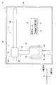
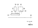
- FIG. 1 shows a structure manufacturing apparatus. It is a block diagram which shows a control apparatus. It is a schematic diagram for demonstrating the manufacturing process of the structure in the conventional manufacturing apparatus. It is a schematic diagram for demonstrating the manufacturing process of the structure in the conventional manufacturing apparatus. It is a schematic diagram for demonstrating the manufacturing process of the structure in the conventional manufacturing apparatus. It is a schematic diagram for demonstrating the manufacturing process of the structure in the conventional manufacturing apparatus. It is a schematic diagram for demonstrating the manufacturing process of the structure in the conventional manufacturing apparatus. It is a schematic diagram for demonstrating the manufacturing process of the structure in the manufacturing apparatus of 1st Example. It is a schematic diagram for demonstrating the manufacturing process of the structure in the manufacturing apparatus of 1st Example. It is a schematic diagram for demonstrating the manufacturing process of the structure in the manufacturing apparatus of 1st Example. It is a schematic diagram for demonstrating the manufacturing process of the structure in the manufacturing apparatus of 2nd Example.
- FIG. 1 shows a structure manufacturing apparatus 10.
- the structure manufacturing apparatus (hereinafter may be abbreviated as “manufacturing apparatus”) 10 includes a transport apparatus 20, a modeling unit 22, and a control apparatus (see FIG. 2) 26.
- the conveying device 20 and the modeling unit 22 are disposed on the base 28 of the manufacturing apparatus 10.
- the base 28 has a generally rectangular shape.
- the longitudinal direction of the base 28 is orthogonal to the X-axis direction
- the short direction of the base 28 is orthogonal to both the Y-axis direction, the X-axis direction, and the Y-axis direction.
- the direction will be described as the Z-axis direction.
- the transport device 20 includes an X-axis slide mechanism 30 and a Y-axis slide mechanism 32.
- the X-axis slide mechanism 30 has an X-axis slide rail 34 and an X-axis slider 36.
- the X-axis slide rail 34 is disposed on the base 28 so as to extend in the X-axis direction.
- the X-axis slider 36 is held by an X-axis slide rail 34 so as to be slidable in the X-axis direction.
- the X-axis slide mechanism 30 has an electromagnetic motor (see FIG. 2) 38, and the X-axis slider 36 moves to an arbitrary position in the X-axis direction by driving the electromagnetic motor 38.
- the Y axis slide mechanism 32 includes a Y axis slide rail 50 and a stage 52.
- the Y-axis slide rail 50 is disposed on the base 28 so as to extend in the Y-axis direction, and is movable in the X-axis direction.
- One end of the Y-axis slide rail 50 is connected to the X-axis slider 36.
- a stage 52 is held on the Y-axis slide rail 50 so as to be slidable in the Y-axis direction.
- the Y-axis slide mechanism 32 has an electromagnetic motor (see FIG. 2) 56, and the stage 52 moves to an arbitrary position in the Y-axis direction by driving the electromagnetic motor 56.
- the stage 52 moves to an arbitrary position on the base 28 by driving the X-axis slide mechanism 30 and the Y-axis slide mechanism 32.
- the stage 52 has a base 60, a holding device 62, and a lifting device 64.
- the base 60 is formed in a flat plate shape, and a base material is placed on the upper surface.
- the holding device 62 is provided on both sides of the base 60 in the X-axis direction. And the both base parts of the X-axis direction of the base material mounted in the base 60 are pinched
- the lifting device 64 is disposed below the base 60 and lifts the base 60.
- the modeling unit 22 is a unit that models a structure on a base material (see FIG. 2) 70 placed on the base 60 of the stage 52, and includes a printing unit 72 and a curing unit 74.
- the printing unit 72 has an inkjet head (see FIG. 2) 76.
- a discharge port (see FIG. 3) 78 is formed on the lower surface of the ink jet head 76, and the ink jet head 76 has an ultraviolet curable resin on the substrate 70 placed on the base 60 from the discharge port 78. Is discharged.
- the inkjet head 76 may be, for example, a piezo method using a piezoelectric element, or a thermal method in which a resin is heated to generate bubbles and ejected from a nozzle.
- the curing unit 74 includes an irradiation device (see FIG. 2) 82.
- An irradiation port 86 is formed on the lower surface of the irradiation device 82 and has a mercury lamp as a light source.
- the irradiation device 82 irradiates ultraviolet rays from the irradiation port 86 toward the ultraviolet curable resin discharged onto the base material 70. Thereby, the ultraviolet curable resin discharged on the base material 70 is cured, and a resin layer is formed.
- the irradiation device 82 has a shutter 88 (see FIG. 3). The shutter 88 slides between a state where the irradiation port 86 is opened and a state where it is closed.
- the irradiation device 82 is switched between a state in which ultraviolet irradiation is permitted and a state in which ultraviolet irradiation is prohibited.
- the inkjet head 76 and the irradiation device 82 are arranged side by side in the X-axis direction.
- the control device 26 includes a controller 102 and a plurality of drive circuits 104 as shown in FIG.
- the plurality of drive circuits 104 are connected to the electromagnetic motors 38 and 56, the holding device 62, the lifting device 64, the inkjet head 76, and the irradiation device 82.
- the controller 102 includes a CPU, a ROM, a RAM, and the like, mainly a computer, and is connected to a plurality of drive circuits 104. Thereby, the operation of the conveying device 20 and the modeling unit 22 is controlled by the controller 102.
- a resin layer is formed by curing a thin-film ultraviolet curable resin, and a plurality of the resin layers are stacked to form a three-dimensional structure having an arbitrary shape.
- the base material 70 is set on the base 60 of the stage 52.
- the stage 52 is moved to a position that coincides with the coordinate position of the inkjet head 76 and the irradiation device 82 in the Y-axis direction by the operation of the Y-axis slide mechanism 32. At this time, the stage 52 is moved so as to be positioned on the side of the inkjet head 76.
- the stage 52 is moved downward of the inkjet head 76 by the operation of the X-axis slide mechanism 30.
- the inkjet head 76 discharges the ultraviolet curable resin 110 onto the substrate 70 in a thin film shape.
- the stage 52 is moved downward of the irradiation device 82 as shown in FIG.
- the irradiation device 82 irradiates the thin-film ultraviolet curable resin 110 with ultraviolet rays.
- the ultraviolet curable resin 110 is cured, and a thin resin layer 112 is formed on the substrate 70.
- the shutter 88 is slid to a position where the irradiation port 86 is opened.
- the stage 52 is moved below the inkjet head 76, and the ultraviolet curable resin 110 is discharged onto the resin layer 112 by the inkjet head 76 in a thin film shape. Then, the stage 52 is moved below the irradiation device 82, and the ultraviolet curable resin 110 is irradiated with ultraviolet rays by the irradiation device 82, whereby the ultraviolet curable resin 110 is cured. Thereby, the resin layer is laminated on the resin layer. As described above, the discharge of the ultraviolet curable resin by the inkjet head 76 and the irradiation of the ultraviolet ray by the irradiation device 82 are repeated, so that the resin layer is laminated and a three-dimensional structure is formed.
- the stage 52 moves, the light irradiated by the irradiation device 82 enters the ink jet head 76, and there is a possibility that the discharge port 78 of the ink jet head 76 is clogged by the light.
- the stage 52 is moved away from the lower side of the irradiation device 82 as shown in FIG. Therefore, the stage 52 is not positioned below the irradiation port 86 of the irradiation device 82, and the ultraviolet light irradiated from the irradiation port 86 is irradiated to the upper surface of the base 28.
- the ultraviolet rays applied to the upper surface of the base 28 are reflected on the upper surface.
- the inkjet head 76 and the irradiation device 82 are disposed adjacent to each other at relatively close positions so as to continuously discharge the ultraviolet curable resin and irradiate the ultraviolet curable resin with ultraviolet rays. For this reason, the light reflected from the upper surface of the base 28 enters the ejection port 78 of the inkjet head 76. As a result, the ultraviolet curable resin is cured at the discharge port 78 of the inkjet head 76 and the discharge port 78 of the inkjet head 76 may be clogged.
- the stage 52 is moved below the inkjet head 76 as shown in FIG.
- the stage 52 is not positioned below the irradiation port 86 of the irradiation device 82, and the ultraviolet light irradiated from the irradiation port 86 is reflected by the upper surface of the base 28, and the reflected ultraviolet light is reflected by the inkjet head 76. Is incident on the discharge port 78.
- the ultraviolet curable resin is cured at the discharge port 78 of the inkjet head 76 and the discharge port 78 of the inkjet head 76 may be clogged.
- a pair of incident prevention units 120 is provided on the stage 52.
- the incident prevention unit 120 includes a flat plate portion 122 and a bent portion 124.
- the flat plate portion 122 has a generally rectangular plate shape, and the bent portion 124 has a shape in which one side of the flat plate portion 122 is bent downward by 90 degrees.
- the pair of incident prevention units 120 are fixed to both edge portions of the stage 52 in the X-axis direction at the bent portions 124, and the flat plate portion 122 extends in the X-axis direction.
- the incident preventing unit 120 is formed of stainless steel (SUS).
- the incident prevention unit 120 on the stage 52, it becomes possible to prevent the ultraviolet rays from entering the ejection port 78 of the inkjet head 76.
- the stage 52 is not located below the irradiation port 86 of the irradiation device 82 as shown in FIG.
- the flat plate portion 122 of the unit 120 extends in the moving direction of the stage 52. For this reason, the ultraviolet rays reflected by the upper surface of the base 28 are blocked by the flat plate portion 122. Thereby, it is possible to prevent the ultraviolet rays irradiated by the irradiation device 82 from entering the ejection port 78 of the inkjet head 76.
- the stage 52 is not positioned below the irradiation port 86 of the irradiation device 82 as shown in FIG. Further, the flat plate portion 122 of the incident preventing unit 120 is located. For this reason, the ultraviolet rays irradiated from the irradiation device 82 are irradiated to the flat plate portion 122 and reflected by the upper surface of the flat plate portion 122.
- the ultraviolet light reflected by the upper surface of the flat plate portion 122 is reflected only at a short distance and falls within the reflection range of the ultraviolet light reflected by the upper surface of the flat plate portion 122.
- the discharge port 78 of the inkjet head 76 is not located. For this reason, it becomes possible to prevent the ultraviolet rays irradiated by the irradiation device 82 from entering the ejection port 78 of the inkjet head 76.
- the ultraviolet rays are prevented from entering the ejection port 78 of the inkjet head 76.
- the incident preventing unit 120 is formed of stainless steel as described above. Since stainless steel is a material having a relatively high thermal conductivity, thermal energy is likely to diffuse. For this reason, it becomes possible to suppress suitably the temperature rise by the light with which the incident prevention unit 120 was irradiated.
- the operation of the shutter 88 is controlled as the stage 52 moves. Specifically, when the stage 52 is below the irradiation port 86 of the irradiation device 82, that is, when the stage 52 is in the irradiation range of the ultraviolet rays irradiated from the irradiation port 86, the shutter 88 is opened and ultraviolet irradiation is performed. Permissible.
- the shutter 88 is closed and ultraviolet irradiation is prohibited. Is done. Accordingly, for example, as shown in FIG. 9, when the stage 52 is separated from the lower part of the irradiation device 82 to some extent, the incident prevention unit 120 cannot prevent the ultraviolet rays from being incident on the ejection port 78, but the shutter 88 By prohibiting the irradiation of ultraviolet rays, it becomes possible to prevent the ultraviolet rays from entering the discharge port 78.
- the incidence of ultraviolet rays to the discharge port 78 is prevented by the arrangement of the incident preventing unit 120 on the stage 52 and the operation of the shutter 88, but the manufacturing of the second embodiment is performed.
- ultraviolet rays are prevented from entering the discharge port 78 only by disposing the incident preventing unit on the stage 52.
- the manufacturing apparatus of the second embodiment has substantially the same configuration as the manufacturing apparatus 10 of the first embodiment, except for the incident prevention unit. For this reason, in 2nd Example, it demonstrates centering on an incident prevention unit, and it abbreviate
- a pair of incident prevention units 130 and 132 are provided on the stage 52 as shown in FIG.
- the incident prevention units 130 and 132 are formed of a resin and have a so-called bellows shape in which flat plate folds and valley folds are repeated. Thereby, the incidence preventing units 130 and 132 can be expanded and contracted.
- a pair of support bases 136 and 138 are installed on both ends in the X-axis direction on the upper surface of the base 28.
- the incident prevention unit 130 is fixed to the support stand 136 at one end, and is fixed to the edge of the stage 52 facing the support stand 136 at the other end.
- the incident preventing unit 132 is fixed to the support base 138 at one end, and is fixed to the edge of the stage 52 facing the support base 138 at the other end.
- the incident preventing units 130 and 132 expand and contract as the stage 52 moves in the X-axis direction.
- the incident prevention units 130 and 132 cover the base 28 regardless of the position of the stage 52 moved. For this reason, when the stage 52 moves below the irradiation device 82 and the stage 52 is located in the ultraviolet irradiation range by the irradiation device 82, the irradiation light from the irradiation device 82 is irradiated toward the stage 52. Is done. This makes it possible to cure the ultraviolet curable resin discharged onto the base material 70 of the stage 52.
- the stage 52 moves from below the irradiation device 82 and the stage 52 is not positioned in the ultraviolet irradiation range by the irradiation device 82, the irradiation light from the irradiation device 82 enters the incident preventing units 130 and 132. Irradiated towards.
- the ultraviolet rays applied to the incident preventing units 130 and 132 are reflected by the incident preventing units 130 and 132, but the reflection range of the reflected light is relatively small, so that it does not enter the ejection port 78 of the inkjet head 76.
- the incident prevention units 130 and 132 are always located below the irradiation device 82, and the base 28 is not exposed. For this reason, even when the stage 52 is moved to a position away from the irradiation device 82, it is possible to prevent the ultraviolet rays from entering the discharge port 78. Thereby, in the manufacturing apparatus of the second embodiment, it is possible to prevent the ultraviolet rays from entering the discharge port 78 only by the incidence preventing units 130 and 132 without providing the shutter 88.
- the incident preventing units 130 and 132 are formed of resin as described above, and a metal filler (fine powder) is mixed in the resin. For this reason, the thermal conductivity of the resin is relatively high. Thereby, also in the manufacturing apparatus of 2nd Example, similarly to the manufacturing apparatus 10 of 1st Example, it becomes possible to suppress suitably the temperature rise by the light with which the incident prevention units 130 and 132 were irradiated.
- the manufacturing apparatus 10 is an example of a three-dimensional molded item modeling apparatus.
- the transport device 20 is an example of a moving device.
- the control device 26 is an example of a control device.
- the stage 52 is an example of a stage.
- the ink jet head 76 is an example of an ejection device.
- the irradiation device 82 is an example of an irradiation device.
- the shutter 88 is an example of a shutter.
- the incidence prevention unit 120 is an example of an incidence prevention body.
- the incident prevention unit 130 is an example of an incident prevention body.
- the incident prevention unit 132 is an example of an incident prevention body.
- the support stand 136 is an example of a support part.
- the support base 138 is an example of a support part.
- the ultraviolet rays are prevented from entering the discharge port 78 by the arrangement of the incident prevention unit 120 and the operation control of the shutter 88. It is possible to prevent ultraviolet rays from entering the discharge port 78 only by control. That is, without providing the incident prevention unit 120 on the stage 52, when the stage 52 is in the irradiation range of the irradiation device 82, the shutter 88 is opened, and when the stage 52 is not in the irradiation range of the irradiation device 82, the shutter 88. It is also possible to prevent the ultraviolet rays from entering the discharge port 78 by closing.
Landscapes
- Engineering & Computer Science (AREA)
- Mechanical Engineering (AREA)
- Chemical & Material Sciences (AREA)
- Manufacturing & Machinery (AREA)
- Materials Engineering (AREA)
Abstract
紫外線硬化樹脂を吐出するインクジェットヘッド76と、紫外線を照射する照射装置82と、構造物を製造するためのステージ52とを有する製造装置において、ステージ上に紫外線硬化樹脂が吐出され、その紫外線硬化樹脂に紫外線が照射される。これにより、紫外線硬化樹脂が硬化し、樹脂層が形成される。さらに、紫外線硬化樹脂の吐出と、紫外線の照射とが繰り返されることで、複数層の樹脂層が積層され、構造物が形成される。この製造装置では、ステージ52の両縁部に、1対の入射防止ユニット120が配設されている。入射防止ユニット120は、ステージ52の移動方向に延び出しており、照射装置によって照射された紫外線を遮る。これにより、吐出装置の吐出口への紫外線の入射を防止することが可能となり、吐出口での紫外線硬化樹脂の硬化を防止することが可能となる。
Description
本発明は、紫外線硬化樹脂によって3次元造形物を造形する3次元造形物造形装置に関する。
近年、紫外線硬化樹脂によって3次元造形物を造形するための技術が開発されている。詳しくは、吐出装置によって紫外線硬化樹脂を薄膜状に吐出し、その紫外線硬化樹脂に紫外線を照射することで硬化させる。これにより、紫外線硬化樹脂の樹脂層が形成される。そして、紫外線硬化樹脂の吐出と、紫外線の照射とが繰り返されることで、複数層の樹脂層が積層され、3次元造形物が造形される。この際、照射装置から照射される紫外線が、吐出装置の吐出口に入射すると、吐出口で紫外線硬化樹脂が硬化し、吐出口が詰まる虞がある。このため、下記特許文献に記載されているように、シャッタが設けられた照射装置が存在し、この照射装置では、紫外線硬化樹脂に紫外線が照射される際にのみ、シャッタが開放され、紫外線の照射時以外には、シャッタが閉じられる。これにより、吐出装置の吐出口への紫外線の入射を防止することが可能となる。
上記特許文献に記載の技術によれば、吐出装置の吐出口への紫外線の入射を防止することが可能となる。しかしながら、紫外線硬化樹脂の吐出と、紫外線の照射とが連続的に行われる際に、シャッタの開閉を待機する場合があり、このような場合には、サイクルタイムが長くなる虞がある。本発明は、そのような実情に鑑みてなされたものであり、吐出装置の吐出口への紫外線の入射を防止するとともに、サイクルタイムの遅延を防止することを課題とする。
上記課題を解決するために、本発明の3次元造形物造形装置は、光の照射により硬化する硬化性樹脂を吐出する吐出装置と、前記吐出装置により吐出された硬化性樹脂に光を照射する照射装置と、前記吐出装置と前記照射装置との下方に配置され、前記吐出装置により吐出された硬化性樹脂に前記照射装置からの光が照射されるステージと、前記吐出装置および前記照射装置と、前記ステージとを相対的に移動させる移動装置と、前記ステージに設けられ、前記照射装置により照射された光の前記吐出装置への入射を防止するための入射防止体とを備えたことを特徴とする。
本発明の3次元造形物造形装置では、照射装置により照射された光の吐出装置への入射を防止するための入射防止体が、ステージに設けられている。つまり、本発明の3次元造形物造形装置では、照射装置の照射光から照射される光をシャッタにより遮ることなく、吐出装置の吐出口への紫外線の入射を防止することが可能となる。これにより、吐出装置の吐出口への紫外線の入射を防止するとともに、サイクルタイムの遅延を防止することが可能となる。
[第1実施例]
<製造装置の構成>
図1に構造物製造装置10を示す。構造物製造装置(以下、「製造装置」と略す場合がある)10は、搬送装置20と、造形ユニット22と、制御装置(図2参照)26とを備える。それら搬送装置20と造形ユニット22とは、製造装置10のベース28の上に配置されている。ベース28は、概して長方形状をなしており、以下の説明では、ベース28の長手方向をX軸方向、ベース28の短手方向をY軸方向、X軸方向及びY軸方向の両方に直交する方向をZ軸方向と称して説明する。
<製造装置の構成>
図1に構造物製造装置10を示す。構造物製造装置(以下、「製造装置」と略す場合がある)10は、搬送装置20と、造形ユニット22と、制御装置(図2参照)26とを備える。それら搬送装置20と造形ユニット22とは、製造装置10のベース28の上に配置されている。ベース28は、概して長方形状をなしており、以下の説明では、ベース28の長手方向をX軸方向、ベース28の短手方向をY軸方向、X軸方向及びY軸方向の両方に直交する方向をZ軸方向と称して説明する。
搬送装置20は、X軸スライド機構30と、Y軸スライド機構32とを備えている。そのX軸スライド機構30は、X軸スライドレール34とX軸スライダ36とを有している。X軸スライドレール34は、X軸方向に延びるように、ベース28の上に配設されている。X軸スライダ36は、X軸スライドレール34によって、X軸方向にスライド可能に保持されている。さらに、X軸スライド機構30は、電磁モータ(図2参照)38を有しており、電磁モータ38の駆動により、X軸スライダ36がX軸方向の任意の位置に移動する。また、Y軸スライド機構32は、Y軸スライドレール50とステージ52とを有している。Y軸スライドレール50は、Y軸方向に延びるように、ベース28の上に配設されており、X軸方向に移動可能とされている。そして、Y軸スライドレール50の一端部が、X軸スライダ36に連結されている。そのY軸スライドレール50には、ステージ52が、Y軸方向にスライド可能に保持されている。さらに、Y軸スライド機構32は、電磁モータ(図2参照)56を有しており、電磁モータ56の駆動により、ステージ52がY軸方向の任意の位置に移動する。これにより、ステージ52は、X軸スライド機構30及びY軸スライド機構32の駆動により、ベース28上の任意の位置に移動する。
ステージ52は、基台60と、保持装置62と、昇降装置64とを有している。基台60は、平板状に形成され、上面に基材が載置される。保持装置62は、基台60のX軸方向の両側部に設けられている。そして、基台60に載置された基材のX軸方向の両縁部が、保持装置62によって挟まれることで、基材が固定的に保持される。また、昇降装置64は、基台60の下方に配設されており、基台60を昇降させる。
造形ユニット22は、ステージ52の基台60に載置された基材(図2参照)70の上に構造物を造形するユニットであり、印刷部72と、硬化部74とを備えている。印刷部72は、インクジェットヘッド(図2参照)76を有している。インクジェットヘッド76の下面には、吐出口(図3参照)78が形成されており、インクジェットヘッド76は、その吐出口78から、基台60に載置された基材70の上に紫外線硬化樹脂を吐出する。なお、インクジェットヘッド76は、例えば、圧電素子を用いたピエゾ方式でもよく、樹脂を加熱して気泡を発生させノズルから吐出するサーマル方式でもよい。
硬化部74は、照射装置(図2参照)82を備えている。照射装置82の下面には、照射口86が形成されており、光源として水銀ランプを有している。そして、照射装置82は、その照射口86から、基材70の上に吐出された紫外線硬化樹脂に向かって紫外線を照射する。これにより、基材70の上に吐出された紫外線硬化樹脂が硬化し、樹脂層が形成される。さらに、照射装置82は、シャッタ(図3参照)88を有している。シャッタ88は、照射口86を開放した状態と塞いだ状態との間でスライドする。これにより、照射装置82は、紫外線の照射が許容された状態と、紫外線の照射が禁止された状態とで切り替えられる。なお、造形ユニット22において、インクジェットヘッド76と照射装置82とは、X軸方向に並んで配設されている。
制御装置26は、図2に示すように、コントローラ102と、複数の駆動回路104とを備えている。複数の駆動回路104は、上記電磁モータ38,56、保持装置62、昇降装置64、インクジェットヘッド76、照射装置82に接続されている。コントローラ102は、CPU,ROM,RAM等を備え、コンピュータを主体とするものであり、複数の駆動回路104に接続されている。これにより、搬送装置20、造形ユニット22の作動が、コントローラ102によって制御される。
<製造装置の作動>
製造装置10では、上述した構成によって、薄膜状の紫外線硬化樹脂を硬化させることで樹脂層を形成し、その樹脂層を複数、積層させることで、任意の形状の3次元構造物が造形される。具体的には、ステージ52の基台60に基材70がセットされる。次に、ステージ52が、Y軸スライド機構32の作動により、インクジェットヘッド76および照射装置82のY軸方向の座標位置と一致する位置に移動される。この際、ステージ52は、インクジェットヘッド76の側方に位置するように移動される。そして、ステージ52が、X軸スライド機構30の作動により、インクジェットヘッド76の下方に向かって移動される。次に、図3に示すように、インクジェットヘッド76が基材70の上に紫外線硬化樹脂110を薄膜状に吐出する。続いて、ステージ52が、図4に示すように、照射装置82の下方に向かって移動される。この際、照射装置82が、その薄膜状の紫外線硬化樹脂110に紫外線を照射する。これにより、紫外線硬化樹脂110が硬化し、基材70の上に薄膜状の樹脂層112が形成される。なお、紫外線硬化樹脂110に紫外線が照射される際に、シャッタ88は照射口86を開放する位置にスライドされている。
製造装置10では、上述した構成によって、薄膜状の紫外線硬化樹脂を硬化させることで樹脂層を形成し、その樹脂層を複数、積層させることで、任意の形状の3次元構造物が造形される。具体的には、ステージ52の基台60に基材70がセットされる。次に、ステージ52が、Y軸スライド機構32の作動により、インクジェットヘッド76および照射装置82のY軸方向の座標位置と一致する位置に移動される。この際、ステージ52は、インクジェットヘッド76の側方に位置するように移動される。そして、ステージ52が、X軸スライド機構30の作動により、インクジェットヘッド76の下方に向かって移動される。次に、図3に示すように、インクジェットヘッド76が基材70の上に紫外線硬化樹脂110を薄膜状に吐出する。続いて、ステージ52が、図4に示すように、照射装置82の下方に向かって移動される。この際、照射装置82が、その薄膜状の紫外線硬化樹脂110に紫外線を照射する。これにより、紫外線硬化樹脂110が硬化し、基材70の上に薄膜状の樹脂層112が形成される。なお、紫外線硬化樹脂110に紫外線が照射される際に、シャッタ88は照射口86を開放する位置にスライドされている。
樹脂層112が形成されると、ステージ52がインクジェットヘッド76の下方に移動され、樹脂層112の上に、インクジェットヘッド76によって、紫外線硬化樹脂110が薄膜状に吐出される。そして、ステージ52が照射装置82の下方に移動され、照射装置82によって、紫外線硬化樹脂110に紫外線が照射されることで、紫外線硬化樹脂110が硬化する。これにより、樹脂層の上に、樹脂層が積層される。このように、インクジェットヘッド76による紫外線硬化樹脂の吐出と、照射装置82による紫外線の照射とが繰り返されることで、樹脂層が積層され、3次元構造物が造形される。
ただし、ステージ52の移動に伴って、照射装置82によって照射された光が、インクジェットヘッド76に入射し、その光によって、インクジェットヘッド76の吐出口78が詰まる虞がある。詳しくは、例えば、紫外線硬化樹脂110への紫外線の照射が完了するタイミングでは、図5に示すように、ステージ52が照射装置82の下方から離間する方向に移動している。このため、照射装置82の照射口86の下方に、ステージ52は位置しておらず、照射口86から照射された紫外線は、ベース28の上面に照射される。ベース28の上面に照射された紫外線は、その上面において反射する。なお、インクジェットヘッド76と照射装置82とは、紫外線硬化樹脂の吐出と、紫外線硬化樹脂への紫外線の照射とを連続して行うべく、比較的、近い位置に隣り合って配設されている。このため、ベース28の上面で反射した光が、インクジェットヘッド76の吐出口78に入射する。これにより、インクジェットヘッド76の吐出口78において、紫外線硬化樹脂が硬化し、インクジェットヘッド76の吐出口78が詰まる虞がある。
また、例えば、ステージ52がインクジェットヘッド76の下方に移動される前には、図6に示すように、ステージ52がインクジェットヘッド76の下方に向かって移動される。この際、照射装置82の照射口86の下方に、ステージ52は位置しておらず、照射口86から照射された紫外線は、ベース28の上面で反射し、その反射した紫外線が、インクジェットヘッド76の吐出口78に入射する。これにより、インクジェットヘッド76の吐出口78において、紫外線硬化樹脂が硬化し、インクジェットヘッド76の吐出口78が詰まる虞がある。
このように、ステージ52の移動に伴って、照射装置82の照射口86の下方にステージ52が位置していない際に、照射装置82から照射された紫外線がインクジェットヘッド76の吐出口78に入射し、吐出口78において紫外線硬化樹脂が硬化する虞がある。このようなことに鑑みて、図7に示すように、ステージ52に1対の入射防止ユニット120が設けられている。入射防止ユニット120は、平板部122と屈曲部124とを含む。平板部122は、概して矩形の板状をなし、屈曲部124は、平板部122の1辺が下方に90度に屈曲された形状をなしている。そして、1対の入射防止ユニット120は、ステージ52のX軸方向における両縁部に、屈曲部124において固定されており、平板部122が、X軸方向に延び出している。なお、入射防止ユニット120は、ステンレス鋼(SUS)により成形されている。
このように、入射防止ユニット120がステージ52に設けられることで、インクジェットヘッド76の吐出口78への紫外線の入射を防止することが可能となる。詳しくは、例えば、ステージ52がインクジェットヘッド76の下方に移動される前には、図7に示すように、照射装置82の照射口86の下方に、ステージ52は位置していないが、入射防止ユニット120の平板部122が、ステージ52の移動方向に向かって延び出している。このため、ベース28の上面で反射した紫外線が、平板部122によって遮られる。これにより、照射装置82によって照射された紫外線のインクジェットヘッド76の吐出口78への入射を防止することが可能となる。
また、例えば、紫外線硬化樹脂110への紫外線の照射が完了するタイミングでは、図8に示すように、ステージ52は照射装置82の照射口86の下方に位置していないが、照射口86の下方に、入射防止ユニット120の平板部122が位置している。このため、照射装置82から照射された紫外線は、平板部122に照射され、その平板部122の上面で反射する。照射装置82とステージ52との間の距離は、比較的、短いため、平板部122の上面で反射した紫外線は、近距離にのみ反射し、平板部122の上面で反射した紫外線の反射範囲に、インクジェットヘッド76の吐出口78は位置していない。このため、照射装置82によって照射された紫外線のインクジェットヘッド76の吐出口78への入射を防止することが可能となる。このように、入射防止ユニット120がステージ52に設けられることで、インクジェットヘッド76の吐出口78への紫外線の入射が防止されている。
また、入射防止ユニット120は、上述したように、ステンレス鋼により成形されている。ステンレス鋼は、比較的、熱伝導率が高い素材であるため、熱エネルギーが拡散し易い。このため、入射防止ユニット120に照射された光による温度上昇を好適に抑制することが可能となる。
さらに、製造装置10では、ステージ52の移動に伴って、シャッタ88の作動が制御される。詳しくは、照射装置82の照射口86の下方にステージ52が有る場合、つまり、照射口86から照射された紫外線の照射範囲にステージ52が有る場合に、シャッタ88が開放され、紫外線の照射が許容される。一方、照射装置82の照射口86の下方にステージ52が無い場合、つまり、照射口86から照射された紫外線の照射範囲にステージ52が無い場合に、シャッタ88が閉じられ、紫外線の照射が禁止される。これにより、例えば、図9に示すように、ステージ52が、照射装置82の下方から、ある程度離れた場合には、入射防止ユニット120によって紫外線の吐出口78への入射を防止できないが、シャッタ88によって紫外線の照射が禁止されることで、吐出口78への紫外線の入射を防止することが可能となる。
[第2実施例]
第1実施例の製造装置10では、ステージ52への入射防止ユニット120の配設と、シャッタ88の作動によって、吐出口78への紫外線の入射が防止されているが、第2実施例の製造装置では、ステージ52への入射防止ユニットの配設のみによって、吐出口78への紫外線の入射が防止される。なお、第2実施例の製造装置は、入射防止ユニットを除いて、第1実施例の製造装置10と略同じ構成である。このため、第2実施例では、入射防止ユニットを中心に説明し、同様の機能の構成要素については、第1実施例の製造装置10と同じ符号を用いて、説明を省略する。
第1実施例の製造装置10では、ステージ52への入射防止ユニット120の配設と、シャッタ88の作動によって、吐出口78への紫外線の入射が防止されているが、第2実施例の製造装置では、ステージ52への入射防止ユニットの配設のみによって、吐出口78への紫外線の入射が防止される。なお、第2実施例の製造装置は、入射防止ユニットを除いて、第1実施例の製造装置10と略同じ構成である。このため、第2実施例では、入射防止ユニットを中心に説明し、同様の機能の構成要素については、第1実施例の製造装置10と同じ符号を用いて、説明を省略する。
第2実施例の製造装置では、図10に示すように、ステージ52に1対の入射防止ユニット130,132が設けられている。入射防止ユニット130,132は、樹脂により成形されており、平板の山折りと谷折りとが繰り返された形状、所謂、蛇腹形状とされている。これにより、入射防止ユニット130,132は、伸縮可能とされている。また、ベース28の上面には、X軸方向の両端部に、1対の支持台136,138が設置されている。そして、入射防止ユニット130が、一端部において、支持台136に固定され、他端部において、ステージ52の支持台136と向かい合う位置の縁部に固定さている。また、入射防止ユニット132が、一端部において、支持台138に固定され、他端部において、ステージ52の支持台138と向かい合う位置の縁部に固定さている。
このような構造により、ステージ52のX軸方向への移動に伴って、入射防止ユニット130,132は伸縮する。つまり、入射防止ユニット130,132は、ステージ52が何れの位置に移動した場合であっても、ベース28を覆っている。このため、ステージ52が照射装置82の下方に移動し、照射装置82による紫外線の照射範囲に、ステージ52が位置している場合には、照射装置82による照射光が、ステージ52に向かって照射される。これにより、ステージ52の基材70の上に吐出された紫外線硬化樹脂を硬化させることが可能となる。
一方、ステージ52が照射装置82の下方から移動し、照射装置82による紫外線の照射範囲に、ステージ52が位置していない場合には、照射装置82による照射光は、入射防止ユニット130,132に向かって照射される。そして、入射防止ユニット130,132に照射された紫外線は、入射防止ユニット130,132で反射するが、その反射光の反射範囲は、比較的小さいため、インクジェットヘッド76の吐出口78に入射しない。なお、ステージ52が照射装置82から離れた位置に移動した場合であっても、照射装置82の下方には、常時、入射防止ユニット130,132が位置しており、ベース28は露出しない。このため、ステージ52が照射装置82から離れた位置に移動した場合であっても、紫外線の吐出口78への入射を防止することが可能となる。これにより、第2実施例の製造装置では、シャッタ88を設けることなく、入射防止ユニット130,132のみによって、紫外線の吐出口78への入射を防止することが可能となる。
なお、入射防止ユニット130,132は、上述したように、樹脂により成形されているが、その樹脂には、金属製のフィラー(微粉末)が混合されている。このため、その樹脂の熱伝導率は、比較的高い。これにより、第2実施例の製造装置においても、第1実施例の製造装置10と同様に、入射防止ユニット130,132に照射された光による温度上昇を好適に抑制することが可能となる。
ちなみに、上記実施例において、製造装置10は、3次元造形物造形装置の一例である。搬送装置20は、移動装置の一例である。制御装置26は、制御装置の一例である。ステージ52は、ステージの一例である。インクジェットヘッド76は、吐出装置の一例である。照射装置82は、照射装置の一例である。シャッタ88は、シャッタの一例である。入射防止ユニット120は、入射防止体の一例である。入射防止ユニット130は、入射防止体の一例である。入射防止ユニット132は、入射防止体の一例である。支持台136は、支持部の一例である。支持台138は、支持部の一例である。
なお、本発明は、上記実施例に限定されるものではなく、当業者の知識に基づいて種々の変更、改良を施した種々の態様で実施することが可能である。具体的には、例えば、上記第1実施例では、入射防止ユニット120の配設と、シャッタ88の作動制御とによって、紫外線の吐出口78への入射が防止されているが、シャッタ88の作動制御のみによって、紫外線の吐出口78への入射を防止することが可能である。つまり、ステージ52に入射防止ユニット120を設けることなく、照射装置82の照射範囲にステージ52が有る場合に、シャッタ88を開放し、照射装置82の照射範囲にステージ52が無い場合に、シャッタ88を閉じることでも、紫外線の吐出口78への入射を防止することが可能となる。
10:製造装置(3次元造形物造形装置) 20:搬送装置(移動装置) 26:制御装置 52:ステージ 76:インクジェットヘッド(吐出装置) 82:照射装置 88:シャッタ 120:入射防止ユニット(入射防止体) 130:入射防止ユニット(入射防止体) 132:入射防止ユニット(入射防止体) 136:支持台(支持部) 138:支持台(支持部)
Claims (5)
- 光の照射により硬化する硬化性樹脂を吐出する吐出装置と、
前記吐出装置により吐出された硬化性樹脂に光を照射する照射装置と、
前記吐出装置と前記照射装置との下方に配置され、前記吐出装置により吐出された硬化性樹脂に前記照射装置からの光が照射されるステージと、
前記吐出装置および前記照射装置と、前記ステージとを相対的に移動させる移動装置と、
前記ステージに設けられ、前記照射装置により照射された光の前記吐出装置への入射を防止するための入射防止体と
を備えたことを特徴とする3次元造形物造形装置。 - 前記入射防止体が、
前記照射装置とステージとの相対的な移動方向に向かって、前記ステージの縁から延び出すように配設されたことを特徴とする請求項1に記載の3次元造形物造形装置。 - 前記移動装置が、前記ステージを移動させる装置であり、
前記照射装置が、
一端部において、前記ステージに固定され、他端部において、前記造形装置のベース上に設けられた支持部に固定されており、前記ステージの移動に伴って伸縮することを特徴とする請求項1に記載の3次元造形物造形装置。 - 前記照射装置が、
光を照射する照射口を開放した状態と塞いだ状態との間で作動するシャッタを有し、
前記造形装置が、
前記照射装置による光の照射範囲に前記ステージが有る際に、前記シャッタを開放させ、前記照射装置による光の照射範囲に前記ステージが無い際に、前記シャッタを閉じるように、前記シャッタの作動を制御する制御装置を備えることを特徴とする請求項1ないし請求項3のいずれか1つに記載の3次元造形物造形装置。 - 前記入射防止体が、
熱伝導率の高い素材により形成されることを特徴とする請求項1ないし請求項4のいずれか1つに記載の3次元造形物造形装置。
Priority Applications (2)
| Application Number | Priority Date | Filing Date | Title |
|---|---|---|---|
| JP2017530470A JP6591545B2 (ja) | 2015-07-24 | 2015-07-24 | 3次元造形物造形装置 |
| PCT/JP2015/071096 WO2017017726A1 (ja) | 2015-07-24 | 2015-07-24 | 3次元造形物造形装置 |
Applications Claiming Priority (1)
| Application Number | Priority Date | Filing Date | Title |
|---|---|---|---|
| PCT/JP2015/071096 WO2017017726A1 (ja) | 2015-07-24 | 2015-07-24 | 3次元造形物造形装置 |
Publications (1)
| Publication Number | Publication Date |
|---|---|
| WO2017017726A1 true WO2017017726A1 (ja) | 2017-02-02 |
Family
ID=57885490
Family Applications (1)
| Application Number | Title | Priority Date | Filing Date |
|---|---|---|---|
| PCT/JP2015/071096 Ceased WO2017017726A1 (ja) | 2015-07-24 | 2015-07-24 | 3次元造形物造形装置 |
Country Status (2)
| Country | Link |
|---|---|
| JP (1) | JP6591545B2 (ja) |
| WO (1) | WO2017017726A1 (ja) |
Cited By (1)
| Publication number | Priority date | Publication date | Assignee | Title |
|---|---|---|---|---|
| JP2024004362A (ja) * | 2022-06-28 | 2024-01-16 | ホッティーポリマー株式会社 | 立体造形物製造方法 |
Citations (4)
| Publication number | Priority date | Publication date | Assignee | Title |
|---|---|---|---|---|
| JP2002307562A (ja) * | 2001-02-07 | 2002-10-23 | Minolta Co Ltd | 三次元造形装置、および三次元造形方法 |
| JP2005319634A (ja) * | 2004-05-07 | 2005-11-17 | Roland Dg Corp | 三次元造形装置および三次元造形方法 |
| JP2014221538A (ja) * | 2013-05-14 | 2014-11-27 | 富士機械製造株式会社 | 形成方法、および形成装置 |
| JP2015036234A (ja) * | 2013-08-15 | 2015-02-23 | コニカミノルタ株式会社 | 三次元造形装置および三次元造形方法 |
Family Cites Families (3)
| Publication number | Priority date | Publication date | Assignee | Title |
|---|---|---|---|---|
| JP2016030435A (ja) * | 2014-07-30 | 2016-03-07 | 株式会社リコー | 物体造形装置 |
| JP6428049B2 (ja) * | 2014-08-25 | 2018-11-28 | 富士ゼロックス株式会社 | 積層造形装置及び積層造形プログラム |
| JP6493007B2 (ja) * | 2015-06-19 | 2019-04-03 | 富士ゼロックス株式会社 | 造形装置 |
-
2015
- 2015-07-24 JP JP2017530470A patent/JP6591545B2/ja active Active
- 2015-07-24 WO PCT/JP2015/071096 patent/WO2017017726A1/ja not_active Ceased
Patent Citations (4)
| Publication number | Priority date | Publication date | Assignee | Title |
|---|---|---|---|---|
| JP2002307562A (ja) * | 2001-02-07 | 2002-10-23 | Minolta Co Ltd | 三次元造形装置、および三次元造形方法 |
| JP2005319634A (ja) * | 2004-05-07 | 2005-11-17 | Roland Dg Corp | 三次元造形装置および三次元造形方法 |
| JP2014221538A (ja) * | 2013-05-14 | 2014-11-27 | 富士機械製造株式会社 | 形成方法、および形成装置 |
| JP2015036234A (ja) * | 2013-08-15 | 2015-02-23 | コニカミノルタ株式会社 | 三次元造形装置および三次元造形方法 |
Cited By (2)
| Publication number | Priority date | Publication date | Assignee | Title |
|---|---|---|---|---|
| JP2024004362A (ja) * | 2022-06-28 | 2024-01-16 | ホッティーポリマー株式会社 | 立体造形物製造方法 |
| JP7441549B2 (ja) | 2022-06-28 | 2024-03-01 | ホッティーポリマー株式会社 | 立体造形物製造方法 |
Also Published As
| Publication number | Publication date |
|---|---|
| JPWO2017017726A1 (ja) | 2018-05-10 |
| JP6591545B2 (ja) | 2019-10-16 |
Similar Documents
| Publication | Publication Date | Title |
|---|---|---|
| JP6306907B2 (ja) | 立体造形物の製造方法及び製造装置 | |
| US11426906B2 (en) | Imprint apparatus, imprint method, and article manufacturing method | |
| CN102371680B (zh) | 三维造型设备、物体以及制造物体的方法 | |
| JP2018041774A (ja) | インプリント装置および物品製造方法 | |
| JP2014120604A (ja) | インプリント装置、デバイス製造方法及びインプリント装置に用いられる型 | |
| CN110049858B (zh) | 数据转换装置及层叠造型系统 | |
| JP2014221538A (ja) | 形成方法、および形成装置 | |
| WO2018003000A1 (ja) | 回路形成方法 | |
| WO2016147284A1 (ja) | 形成方法及び形成装置 | |
| JPWO2017212567A1 (ja) | 回路形成方法 | |
| JP6591545B2 (ja) | 3次元造形物造形装置 | |
| JP6557563B2 (ja) | 三次元造形装置 | |
| WO2019193644A1 (ja) | 3次元構造物形成方法、および3次元構造物形成装置 | |
| JP6020672B2 (ja) | 3次元造形装置及び造形物の製造方法 | |
| JP2019052325A (ja) | 三次元造形物の製造方法 | |
| WO2016189577A1 (ja) | 配線形成方法 | |
| JP2018078258A (ja) | インプリント装置、インプリント方法、及び物品製造方法 | |
| JP6344447B2 (ja) | 3次元造形装置及び造形物の製造方法 | |
| JPWO2017006412A1 (ja) | 造形装置および造形方法 | |
| JP2014233704A (ja) | 薄膜形成方法及び薄膜形成装置 | |
| JP6663516B2 (ja) | 回路形成方法、および回路形成装置 | |
| JP2015104890A (ja) | 三次元造形装置、三次元造形方法、三次元造形装置の制御用プログラムおよび記録媒体 | |
| WO2019159307A1 (ja) | インクジェット印刷装置 | |
| JP2020077661A (ja) | 回路形成方法 | |
| JP2014236169A (ja) | 薄膜形成方法及び薄膜形成装置 |
Legal Events
| Date | Code | Title | Description |
|---|---|---|---|
| 121 | Ep: the epo has been informed by wipo that ep was designated in this application |
Ref document number: 15899560 Country of ref document: EP Kind code of ref document: A1 |
|
| ENP | Entry into the national phase |
Ref document number: 2017530470 Country of ref document: JP Kind code of ref document: A |
|
| NENP | Non-entry into the national phase |
Ref country code: DE |
|
| 122 | Ep: pct application non-entry in european phase |
Ref document number: 15899560 Country of ref document: EP Kind code of ref document: A1 |