WO2017014142A1 - エンコーダ装置、駆動装置、ステージ装置、ロボット装置及び情報取得方法 - Google Patents
エンコーダ装置、駆動装置、ステージ装置、ロボット装置及び情報取得方法 Download PDFInfo
- Publication number
- WO2017014142A1 WO2017014142A1 PCT/JP2016/070820 JP2016070820W WO2017014142A1 WO 2017014142 A1 WO2017014142 A1 WO 2017014142A1 JP 2016070820 W JP2016070820 W JP 2016070820W WO 2017014142 A1 WO2017014142 A1 WO 2017014142A1
- Authority
- WO
- WIPO (PCT)
- Prior art keywords
- mark
- rotation
- image
- encoder
- processing unit
- Prior art date
- Legal status (The legal status is an assumption and is not a legal conclusion. Google has not performed a legal analysis and makes no representation as to the accuracy of the status listed.)
- Ceased
Links
Images








Classifications
-
- G—PHYSICS
- G01—MEASURING; TESTING
- G01B—MEASURING LENGTH, THICKNESS OR SIMILAR LINEAR DIMENSIONS; MEASURING ANGLES; MEASURING AREAS; MEASURING IRREGULARITIES OF SURFACES OR CONTOURS
- G01B11/00—Measuring arrangements characterised by the use of optical techniques
- G01B11/26—Measuring arrangements characterised by the use of optical techniques for measuring angles or tapers; for testing the alignment of axes
-
- G—PHYSICS
- G01—MEASURING; TESTING
- G01D—MEASURING NOT SPECIALLY ADAPTED FOR A SPECIFIC VARIABLE; ARRANGEMENTS FOR MEASURING TWO OR MORE VARIABLES NOT COVERED IN A SINGLE OTHER SUBCLASS; TARIFF METERING APPARATUS; MEASURING OR TESTING NOT OTHERWISE PROVIDED FOR
- G01D5/00—Mechanical means for transferring the output of a sensing member; Means for converting the output of a sensing member to another variable where the form or nature of the sensing member does not constrain the means for converting; Transducers not specially adapted for a specific variable
- G01D5/26—Mechanical means for transferring the output of a sensing member; Means for converting the output of a sensing member to another variable where the form or nature of the sensing member does not constrain the means for converting; Transducers not specially adapted for a specific variable characterised by optical transfer means, i.e. using infrared, visible, or ultraviolet light
-
- G—PHYSICS
- G01—MEASURING; TESTING
- G01D—MEASURING NOT SPECIALLY ADAPTED FOR A SPECIFIC VARIABLE; ARRANGEMENTS FOR MEASURING TWO OR MORE VARIABLES NOT COVERED IN A SINGLE OTHER SUBCLASS; TARIFF METERING APPARATUS; MEASURING OR TESTING NOT OTHERWISE PROVIDED FOR
- G01D5/00—Mechanical means for transferring the output of a sensing member; Means for converting the output of a sensing member to another variable where the form or nature of the sensing member does not constrain the means for converting; Transducers not specially adapted for a specific variable
- G01D5/26—Mechanical means for transferring the output of a sensing member; Means for converting the output of a sensing member to another variable where the form or nature of the sensing member does not constrain the means for converting; Transducers not specially adapted for a specific variable characterised by optical transfer means, i.e. using infrared, visible, or ultraviolet light
- G01D5/32—Mechanical means for transferring the output of a sensing member; Means for converting the output of a sensing member to another variable where the form or nature of the sensing member does not constrain the means for converting; Transducers not specially adapted for a specific variable characterised by optical transfer means, i.e. using infrared, visible, or ultraviolet light with attenuation or whole or partial obturation of beams of light
- G01D5/34—Mechanical means for transferring the output of a sensing member; Means for converting the output of a sensing member to another variable where the form or nature of the sensing member does not constrain the means for converting; Transducers not specially adapted for a specific variable characterised by optical transfer means, i.e. using infrared, visible, or ultraviolet light with attenuation or whole or partial obturation of beams of light the beams of light being detected by photocells
- G01D5/347—Mechanical means for transferring the output of a sensing member; Means for converting the output of a sensing member to another variable where the form or nature of the sensing member does not constrain the means for converting; Transducers not specially adapted for a specific variable characterised by optical transfer means, i.e. using infrared, visible, or ultraviolet light with attenuation or whole or partial obturation of beams of light the beams of light being detected by photocells using displacement encoding scales
Definitions
- the present invention relates to an encoder device, a drive device, a stage device, a robot device, and an information acquisition method.
- the encoder device that detects rotation information is mounted on various devices such as a drive device (eg, a motor device).
- a drive device eg, a motor device
- the encoder device detects light from a scale provided on the rotation shaft, and acquires rotation information.
- Some encoder devices use a polarizing plate instead of a scale (see, for example, Patent Document 1 below).
- the rotation information of the rotation axis is obtained using an imaging unit that captures a mark including at least one line whose direction is changed by rotation of the rotation axis, and an image obtained by the imaging unit.
- An encoder device including a processing unit for calculating is provided.
- a driving device including the encoder device according to the first aspect and a driving unit that supplies a driving force to the rotating shaft.
- a stage apparatus including a moving body and the driving apparatus according to the second aspect that moves the moving body.
- a robot apparatus including the driving device according to the second aspect and an arm relatively moved by the driving device.
- an image of a mark including at least one line that is provided on the rotation shaft of the driving device and changes its direction by the rotation of the rotation shaft is used, and the mark is obtained using the image obtained by the imaging.
- An information acquisition method is provided that includes detecting the orientation of the rotation axis and calculating rotation information of the rotation axis.
- FIG. 1 It is a figure which shows an example of the encoder apparatus which concerns on embodiment.
- A) is a top view of the encoder apparatus which concerns on embodiment
- B) is a figure which shows the mark part which concerns on embodiment.
- (A) is a figure which shows the encoder apparatus which concerns on a modification
- (B) is a figure which shows an example of the image of the mark imaged by the imaging part which concerns on embodiment. It is a figure which shows the encoder apparatus which concerns on a modification. It is a figure which shows the encoder apparatus which concerns on a modification. It is a figure which shows an example of the drive device which concerns on embodiment. It is a figure which shows an example of the stage apparatus which concerns on embodiment. It is a figure which shows an example of the robot apparatus which concerns on embodiment.
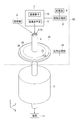
- FIG. 1 is a diagram illustrating an example of an encoder device EC according to the embodiment.
- the encoder device EC images the mark 4 whose direction (for example, the direction on the plane intersecting the rotation axis 3) is changed by the rotation of the rotation axis 3 of the drive unit 2. Further, the encoder device EC calculates rotation information of the rotary shaft 3 using an image obtained by imaging the mark 4.
- the encoder device EC includes a mark unit 5, an illumination unit 6, an imaging unit 7, and an image processing unit 8.
- the storage unit 9 may be provided in the encoder device EC, or may be provided outside the encoder device EC (eg, an external device).
- the image processing unit 8 and the external storage unit 9 are configured to be able to communicate signals, data, and the like wirelessly or by wire. Further, the relative position of the mark 4 and the imaging unit 7 only needs to change with the rotation of the rotating shaft. For example, the mark 4 is fixed to the non-rotating unit, and the imaging unit 7 is rotated with the rotation of the rotating shaft 3. May rotate.
- the drive unit 2 drives the rotary shaft 3 to rotate.
- the drive unit 2 is, for example, a part of the drive device MTR shown later in FIG.
- the drive unit 2 is, for example, an electric motor, but may not be an electric motor.
- the drive unit 2 may be a device having a shaft portion that rotates using hydraulic pressure or pneumatic pressure.
- the rotating shaft 3 is rotated by the driving force (torque) of the driving unit 2.
- the rotating shaft 3 is a shaft (rotor) of the driving unit 2, but may be an axis connected to the shaft of the driving unit 2.
- the rotating shaft 3 may be a shaft in a power transmission unit such as a transmission connected to the shaft of the driving unit 2.
- the rotary shaft 3 may be a shaft connected to the shaft of the drive unit 2 via a power transmission unit.
- the rotary shaft 3 may be a shaft connected to a load.
- the mark 4 is formed on the mark portion 5 provided at the end of the rotating shaft 3.
- the end of the rotating shaft 3 refers to the end surface of the rotating shaft 3 and its vicinity.
- the mark portion 5 may be a part of the rotating shaft 3 or may be another member attached to the end of the rotating shaft 3.
- the mark portion 5 is at or near the end surface of the rotating shaft 3, and the mark 4 is formed on the rotating shaft 3.
- the mark part 5 is provided as a member different from the rotating shaft 3, for example, the mark part 5 can be attached to the end surface of the rotating shaft 3.
- the mark portion 5 is provided at the end of the rotating shaft 3 opposite to the side connected to the load 11 (on the opposite output shaft side).
- the mark portion 5 When the mark portion 5 is provided on the side opposite to the output shaft, it is possible to suppress dirt (eg, oil, oil mist, etc.) from the load 11 and the like from adhering to the mark portion 5.
- the mark unit 5 rotates according to the rotation direction and rotation angle of the rotary shaft 3.
- the mark unit 5 rotates integrally with the rotary shaft 3.
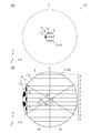
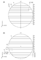
- FIG. 2A is a plan view of the encoder device EC as viewed from the + Z direction
- FIG. 2B is a diagram showing the mark portion 5.
- a mark 4 whose direction is changed by the rotation of the rotary shaft 3 is formed in the mark portion 5.
- the mark 4 is a pattern that can indicate the rotational position of the mark portion 3.
- the orientation (eg, direction) of the mark 4 on the plane intersecting (eg, orthogonal, non-orthogonal) with the rotation axis 3 is changed by the rotation of the rotation axis 3.
- the mark 4 includes at least one line (eg, a plurality of lines 12).
- the mark 4 includes at least one of a straight line (a straight line, a shortest line connecting two points, a line segment) and a curved line, for example.
- the line of the mark 4 has, for example, a strip shape having a finite width with respect to the length direction.
- a strip-like figure having a finite width is referred to as a line (eg, a straight line, a curve, or a line segment) for convenience.
- the at least one line of the mark 4 may be a line including a straight part and a curved part.
- the at least one line of the mark 4 may be a line including a polygonal line part, or may be a line including a polygonal line part and a curved line part.
- the plurality of lines 12 are, for example, line segments, and are arranged in parallel to each other.
- the plurality of lines 12 may be formed with the rotation axis 3 as a reference.
- At least one of the plurality of lines 12 may be formed so as to pass through the center of the rotating shaft 3, and none of the plurality of lines 12 may pass through the center of the rotating shaft 3.
- Each of the plurality of lines 12 is arranged in parallel to a predetermined direction (eg, X direction), and is separated from each other in a cross direction (eg, Y direction, orthogonal direction, non-orthogonal direction) of the predetermined direction.
- a predetermined direction eg, X direction
- a cross direction eg, Y direction, orthogonal direction, non-orthogonal direction
- the number of lines 12 is set to an arbitrary number.
- Each of the plurality of lines 12 may be a line segment connecting two points on the outer periphery of the end surface 10 of the rotating shaft 3.
- the plurality of lines 12 may be arranged in an intersecting direction (Y direction) with respect to at least one of the lines 12.
- the plurality of lines 12 may be arranged at equal intervals, or may be arranged at different intervals.
- the interval d between the plurality of lines 12 is arbitrarily set.
- 2B shows an example in which the plurality of lines 12 are arranged at positions not passing through the rotation center O, but at least one of the plurality of lines 12 is arranged at a position passing through the rotation center O of the rotation shaft 3. May be.
- the number of the lines 12 included in the mark 4 is arbitrary, and may be one or plural.
- the length of the line included in the mark 4 is also arbitrary, and when there are a plurality of lines, they may all be the same length or different lengths. For example, when the mark portion is circular, the length of at least one line may be longer than the radius of the mark portion.
- the mark 4 may be non-linearly symmetric with respect to at least one straight line passing through the rotation center O of the rotation shaft 3. Further, the mark 4 may be axisymmetric with respect to all straight lines passing through the rotation center O of the rotation shaft 3.
- the mark 4 includes the figure 14, and the figure 14 and the plurality of lines 12 can be combined to be non-linearly symmetric with respect to any straight line passing through the rotation center O of the rotation axis 3.
- the figure 14 may be provided only in one of the two regions R1 obtained by dividing the mark portion 5 by a straight line (for example, the straight line L1) passing through the rotation center O of the rotation shaft 3 (for example, only the region R1 in the ⁇ X direction). Good.
- the area where the figure 14 is provided and the area where the figure 14 is not provided may be positioned point-symmetrically with respect to the center of the rotation axis. Further, the area where the figure 14 is provided and the area where the figure 14 is not provided may be provided symmetrically with respect to a straight line L1 passing through the rotation center O of the rotation shaft 3. As will be described later with reference to FIG. 6 and the like, the graphic 14 can be used to distinguish 180 ° rotation (polarity).
- the figure 14 has a shape different from any of the plurality of lines 12, for example.
- the figure 14 has, for example, an arcuate shape including a part of the outer periphery of the end face 10 in the ⁇ X direction.
- the figure 14 has a spread in the rotation direction (circumferential direction) of the rotation shaft 3 when viewed in the central axis direction of the rotation shaft 3 (when the mark 4 is viewed in plan).
- one line arbitrarily selected from the plurality of lines 12 when viewed from the central axis direction of the rotating shaft 3 is defined as a reference line 12x.
- the angle between the reference line 12x and the straight line OE1 connecting one end E1 of the figure 14 in the rotation direction of the rotation axis 3 and the rotation center O of the rotation axis 3 is ⁇ 1, and the other end E2 of the figure 14 in the rotation direction of the rotation axis 3 is.
- ⁇ 1 and ⁇ 2 are in a relationship of 0 ° ⁇ 1 ⁇ 180 ° and 0 ° ⁇ 2 ⁇ 180 °, where ⁇ 2 is an angle between the straight line OE2 connecting the rotation axis 3 and the rotation center O of the rotary shaft 3 and the reference line 12x.
- ⁇ 2 is an angle between the straight line OE2 connecting the rotation axis 3 and the rotation center O of the rotary shaft 3 and the reference line 12x.
- the mark 4 is formed so as to be identifiable (can be distinguished from other parts) on the image captured by the imaging unit 7.
- the line of the mark 4 is, for example, a marking line formed (engraved) on the end face 10.
- the line 12 of the mark 4 may be, for example, a groove, a depression, or a recess formed (engraved) on the end face 10, and the line 12 of the mark 4 may be a protrusion or a structure.
- the plurality of lines 12 are marking lines formed on the end face 10
- at least one of the plurality of lines 12 may have a line depth different from that of the other lines 12, or the other lines 12.
- the line thickness may be different.
- the figure 14 of the mark 4 is, for example, a roughened surface of the end face 10.
- the mark portion 5 is, for example, a part of the rotation shaft 3, but may be a member (a member different from the rotation shaft 3) attached to the rotation shaft 3 (described later in FIG. 13B).
- the mark 4 may be formed on the end surface 10 by printing or the like, or a part of the end surface 10 may be subjected to a surface treatment such as blackening. Further, the mark 4 may be subjected to surface treatment so that the reflectance of light at a part of the end face 10 is higher than that at the other part.
- the mark 4 may be formed over the entire region (eg, the entire surface) of the mark portion 5 (eg, the end surface 10), or may be formed only on a part of the mark portion 5 (eg, the end surface 10).
- the illumination unit 6 illuminates the mark 4.
- the illumination unit 6 is disposed in the vicinity of the mark unit 5 and irradiates the mark 4 with light.
- the illumination unit 6 includes a solid light source such as a chip-type light emitting diode (LED).
- the illumination unit 6 may include a solid light source (eg, a laser diode) other than a light emitting diode, or may include a lamp light source.
- the imaging unit 7 images the mark 4.
- the imaging unit 7 is disposed, for example, in the vicinity of the mark unit 5.
- the imaging unit 7 images the mark 4 from the normal direction (eg, the Z direction) of the end surface 10.
- the imaging unit 7 may image the mark 4 in a state where the mark 4 is illuminated by the illumination unit 6.
- the imaging unit 7 includes, for example, an imaging optical system 17 and an imaging element 18.
- the imaging optical system 17 has a lens and forms an image of the mark 4.
- the image sensor 18 captures an image formed by the imaging optical system 17.
- the image sensor 18 is a solid-state image sensor (two-dimensional image sensor) such as a CCD image sensor or a CMOS image sensor.
- the imaging optical system 17 includes, for example, an autofocus mechanism, and the imaging element 18 images the mark 4 in a state where the focal position of the imaging optical system 17 is focused on the mark 4.
- the imaging unit 7 generates a captured image of the mark 4.
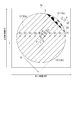
- FIG. 3 is a diagram illustrating an example of an image Im (captured image) captured by the imaging unit 7.
- the imaging unit 7 images the entire area of the mark 4 formed on the mark unit 5. That is, the visual field of the imaging unit 7 may be set in advance in a range including the entire area of the mark 4. Further, the field of view of the imaging unit 7 may be set so that when the entire area of the mark 4 is imaged, a portion other than the mark 4 in the image Im is reduced.
- the visual field center of the imaging unit 7 is set to the rotation center O of the rotation shaft 3 or the vicinity thereof. Note that the imaging unit 7 does not have to image the entire area of the mark 4 and may image a part of the mark 4.
- the imaging unit 7 captures the mark 4 in a plurality of times (for example, scanning), and the image processing unit 8 uses an image obtained by combining two or more of the plurality of images obtained by the plurality of times of imaging.
- the rotation information may be calculated.
- the imaging unit 7 is connected to the image processing unit 8 in a wired or wireless manner so as to be communicable, and supplies (eg, transmits) data of the image Im of the captured mark 4 to the image processing unit 8.
- the image processing unit 8 processes the image Im (see FIG. 3) captured by the imaging unit 7.
- the image processing unit 8 includes, for example, a digital signal processor (DSP), an application specific IC (ASIC), a programmable logic device (PLD), and the like.
- the storage unit 9 is connected to the image processing unit 8 and stores various data.
- the storage unit 9 stores data of the image Im captured by the image capturing unit 7, data being processed by the image processing unit 8, data processed by the image processing unit 8, and data used by the image processing unit 8 for processing (eg, setting) Value, parameter) and the like are stored.
- the storage unit 9 includes, for example, a RAM, a flash memory, a ROM, and the like.
- the image processing unit 8 calculates rotation information of the rotating shaft 3 using the image obtained by the imaging unit 7. For example, the image processing unit 8 detects, determines, or derives the orientation of the mark 4 using the image Im captured by the imaging unit 7 and calculates the rotation information of the rotation shaft 3. The image processing unit 8 detects the rotation information of the rotation shaft 3 based on the plurality of lines 12 shown in the image Im.
- the rotation information is information related to the rotation of the rotation shaft 3 and includes, for example, at least one of a rotation position (angular position) of the rotation shaft 3, a change amount of the rotation position, an angular velocity, and an angular acceleration.
- the rotation position of the rotation shaft 3 may be a rotation angle from a reference position.
- the rotation information may be information that does not distinguish the number of rotations (hereinafter referred to as single rotation information) or information that distinguishes the number of rotations (hereinafter referred to as multi-rotation information).
- single rotation information when the amount of change in the rotational position is 400 °, the single rotation information is represented by a value of 40 ° ignoring the number of rotations (one rotation, 360 °), and the amount of change in the rotational position is 40 °. It is represented by the same value.
- the multi-rotation information is represented by a value of 400 ° or one rotation and 40 ° when the change amount of the rotation position is 400 °, for example.
- the rotation information is represented by a binary number having a predetermined number of bits, for example, and may be a value converted to degrees (deg) or a value converted to radians (rad).
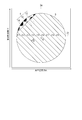
- FIG. 4 is a diagram illustrating an example of rotation information calculation processing by the image processing unit 8.
- the image processing unit 8 rotates information about the rotation shaft 3 based on the number of intersection points P ⁇ b> 1 between a predetermined line segment 20 provided on the image Im by image processing and the images of the plurality of lines 12 on the image Im. Is calculated.
- the image processing unit 8 binarizes the image Im captured by the imaging unit 7 and extracts a plurality of lines 12 from the binarized image by processing such as edge detection and Hough transform.
- the image processing unit 8 represents the extracted plurality of lines 12 by a linear expression indicating the relationship between the coordinates in the horizontal scanning direction and the coordinates in the vertical scanning direction on the image Im. Subsequently, the image processing unit 8 calculates the number of intersection points P1 between the predetermined line segment 20 and the plurality of lines 12 on the image Im.
- the predetermined line segment 20 is described as being parallel to the horizontal scanning direction. However, the predetermined line segment 20 may be non-parallel to the horizontal scanning line, parallel to the vertical scanning line, or horizontal scanning. Either the line or the vertical scan line may be non-parallel.
- the length L of the predetermined line segment 20 is arbitrarily set.
- the predetermined line segment 20 is arranged from the line 12a arranged at one end to the other end in the arrangement direction of the plurality of lines 12 (eg, the direction perpendicular to the line 12). Is set to be equal to or greater than the width B up to the line 12b.
- the coordinates of the intersection point P1 on the image Im are obtained, for example, by solving simultaneous equations of a linear expression representing the image of the line 12 on the image Im and a linear expression representing the predetermined line segment 20.
- the number of intersection points P1 is determined by determining whether each of the plurality of lines 12 has a predetermined line segment 20 and the intersection point P1 within the range of the mark 4, and counting the number of intersection points P1. .
- the angle between the predetermined line segment 20 shown in FIG. 4 and one line 12c of the plurality of lines 12 is ⁇
- the distance between the plurality of lines 12 is d
- the distance between the intersection P1 and the intersection P1 is Assuming X, these relationships are represented by the following formula (1).
- represents an absolute value.
- X
- the number N of the intersection points P1 is expressed by the following formula, for example, where INT (L / X) is an integer part of L / X (the number of intervals of the lines 12 that fit in the section of the predetermined line 20 of length L). It is represented by (2).
- N 100
- L / X is 99 or more and less than 100
- the image processing unit 8 can calculate the angle ⁇ using the intermediate value 99.5 as the value of L / X.
- the angle ⁇ is information representing the direction of the plurality of lines 12 (marks 4).
- the image processing unit 8 detects the direction of the mark 4 by calculating the angle ⁇ based on the plurality of lines 12, and calculates the rotation information of the rotating shaft 3.
- FIG. 5 is a diagram illustrating another example of the rotation information calculation process performed by the image processing unit 8.
- the image processing unit 8 includes a predetermined line segment 21 provided on the image Im and each of the images of the plurality of lines 12 on the image Im. Are obtained, and rotation information is calculated based on the average value ⁇ m of the angles.
- the image processing unit 8 binarizes the image of the mark 4 and extracts a plurality of lines 12, and extracts the extracted lines 12 on the image Im, respectively. Expressed as a linear expression of coordinates.
- the predetermined line segment 21 is set in parallel to the horizontal scanning direction on the image Im.
- ⁇ 1 to ⁇ 9 can be calculated from the slope of the linear expression representing each of the plurality of lines 12.
- the image processing unit 8 calculates the average value ⁇ m of the angles ⁇ 1 to ⁇ 9 as the rotation information of the rotation shaft 3.
- the average value ⁇ m may be, for example, an arithmetic average, a geometric average, or a weighted average (weighted average).
- the detection accuracy of the angles ⁇ 1 to ⁇ 9 is generally higher for the longer line 12 of the plurality of lines 12, and the weighted average weighting coefficient may be an amount proportional to the length of the line 12.
- the image processing unit 8 may detect the orientation of the mark 4 by calculating the angle ⁇ m based on the plurality of lines 12 and calculate the rotation information of the rotating shaft 3. In this way, when averaging the angles (for example, the angles ⁇ 1 to ⁇ 9) between each image of the plurality of lines 12 and the predetermined line segment 21 provided on the image, for example, the mark 4 (for example, the end face 10). ) Can be reduced, and rotation information can be obtained with high accuracy. In addition, when dirt, a crack, etc. exist in a mark part, you may remove as noise in a process part previously. If there is dirt or a flaw in a part of the line segment, the line segment may not be used for angle detection, and information on a part having the fouling or flaw may be interpolated.
- the rotation information calculation processing by the image processing unit 8 is not limited to the examples in FIGS. 4 and 5.
- the image processing unit 8 may acquire the shape information (eg, reference information) of the mark 4 from the storage unit 9 and calculate the rotation information from the shape information and the image of the mark 4 on the image Im.
- the shape information for example, an image in the case where the rotation shaft 3 is at a predetermined rotation position can be created in advance.
- the shape information may be image data of the mark 4 for each predetermined angle from 0 degrees to 360 degrees.
- This image data may be an image captured by the imaging unit 7 or may be a processed image. Further, this image data may be image data acquired without using the imaging unit 7, for example, image data generated by image creation software or the like.
- the image processing unit 8 calculates the correlation between the image Im of the mark 4 imaged by the imaging unit 7 and the shape information such as the image data described above, and calculates the rotation information of the rotation axis from the image Im. it can.
- the image processing unit 8 acquires the image Im of the mark 4 and the shape information (eg, image data) according to each rotation position from the storage unit 9, and compares the image Im with the shape information,
- the rotation information may be calculated.
- the image processing unit 8 calculates the correlation coefficient between the shape information corresponding to each rotation position and the image Im, and sets the rotation position corresponding to the shape information that maximizes the correlation coefficient as the rotation position of the rotation shaft 3. It is good.
- the image processing unit 8 may calculate the rotation position of the rotation shaft 3 using the correlation coefficient between the shape information corresponding to each rotation position and the image Im.
- the image processing unit 8 first calculates the correlation coefficient using the image data for each predetermined angle as the shape information corresponding to each rotation position, and then calculates the top two image data having the higher correlation coefficient.
- the position in the section of the corresponding rotational position may be calculated using the correlation coefficient.
- the image processing unit 8 may perform the above-described correlation coefficient calculation step by step. For example, the image processing unit 8 first calculates a correlation coefficient using a plurality of pieces of image data having a wide angular step as the shape information corresponding to each rotation position, and then calculates the top two correlation coefficients. For the section of the rotational position corresponding to the image data, the rotational position of the rotational shaft 3 may be calculated using a plurality of image data with a small angular increment.
- the image processing unit 8 may calculate the rotational position of the rotational shaft 3 by pattern matching the shape information corresponding to each rotational position and the image Im. For example, the image processing unit 8 first performs pattern matching using image data for each predetermined angle as shape information corresponding to each rotation position, and determines the rotation position corresponding to the shape information that maximizes the pattern match, The rotational position of the rotary shaft 3 may be used. Note that the comparison between the image Im and the image data (eg, calculation of correlation coefficient, pattern matching) may be performed on the entire mark 4 or on a part of the mark 4. For example, the comparison between the image Im and the image data may be performed on all of the plurality of lines 12 in the mark 4 or may be performed on a part of the plurality of lines 12.
- the image processing unit 8 may calculate information other than the rotation position of the rotation shaft 3 as the rotation information, or may not calculate the rotation position of the rotation shaft 3.
- the image processing unit 8 includes, as the rotation information, the number of rotations, the amount of change in the rotation position, the rotation direction, the rotation speed (eg, angular velocity), the rotation acceleration (eg, angular acceleration), and the eccentric information (eg, At least one of an eccentric error and an eccentric angle may be calculated.
- the image processing unit 8 may calculate the rotation direction by calculating the amount of change of the rotation position and discriminating the sign (the direction in which the position of the rotation shaft 3 changes).
- the image processing unit 8 may calculate the number of rotations that takes the rotation direction into account by integrating the amount of change in the rotation position that distinguishes the rotation direction. For example, the image processing unit 8 counts the number of rotations by +1 when the integrated value of the amount of change in the rotational position of the rotating shaft 3 exceeds 360 °, and counts the number of rotations by ⁇ 1 when it falls below ⁇ 360 °. Thus, the rotational speed can be calculated. Further, the image processing unit 8 can calculate the multi-rotation information of the rotation shaft 3 using, for example, information on the rotation speed and the rotation direction. Further, the image processing unit 8 detects, for example, the rotation center O of the image Im of the mark 4 at each time, detects the locus of the rotation center O, and uses the detected locus data of the rotation center O to rotate the rotating shaft 3. May be calculated.
- rotation polarity determination will be described.
- the sampling frequency is smaller than the frequency at which the rotation axis rotates 180 °
- the state where the change amount of the rotational position is 0 ° and the state where it is 180 ° may not be distinguished.
- the encoder device EC has a shape in which the mark 4 is axisymmetric with respect to the straight line L1 passing through the rotation center O, and the amount of change in the rotational position is utilized using this asymmetry. Is distinguished (polarity discrimination) between a state where the angle is 0 ° and a state where the angle is 180 °.
- the mark 4 is axisymmetric with respect to the straight line L1 by providing the figure 14 only in one of the pair of regions R1 across the straight line L1 passing through the rotation center.
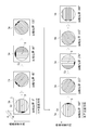
- FIG. 6 is a diagram showing the image Im of the mark 4 imaged by the imaging unit 7 in association with the rotational position of the rotary shaft 3.
- the imaging unit 7 images the mark unit 5 at a predetermined interval (eg, sampling cycle) while the rotating shaft 3 rotates.
- an image obtained by the imaging unit 7 imaging the mark 4 when the rotational position of the rotary shaft 3 is 0 °, 45 °, 90 °, 135 °, 280 °, 225 °, 270 °, 315 °, and 360 °.
- a case where the plurality of lines 12 of the mark 4 are parallel to the X direction (horizontal scanning direction) is set as a reference for the rotational position of the rotary shaft 3 (for example, 0 °).
- the image processing unit 8 detects, for example, the graphic 14 to distinguish between a state where the rotational position is ⁇ ° and a state where the rotational position is ( ⁇ + 180) °. For example, when the angle between the plurality of lines 12 and the horizontal scanning line of the image Im is 0 ° (rotational position is 0 °, 180 °), the image processing unit 8 displays the graphic 14 on the image Im as the rotation center O. It is determined which side is on the line Cy parallel to the vertical scanning line. For example, the image processing unit 8 determines that the rotational position is 0 ° when the graphic 14 is on the left side of the line Cy, and determines that the rotational position is 180 ° when the graphic 14 is on the right side of the line Cy. To do.
- the image processing unit 8 rotates the figure 14 on the image Im. It is determined which side is on the line Cx passing through the center O and parallel to the horizontal scanning line. For example, the image processing unit 8 determines that the rotational position is 90 ° when the graphic 14 is above the line Cx, and the rotational position is 270 ° when the graphic 14 is below the line Cx. judge.
- the image processing unit 8 determines the polarity by determining whether the figure 14 is located in the first quadrant to the fourth quadrant in the orthogonal coordinate system having the rotation center O as the origin on the image Im, for example. You may go.
- polarity determination may be performed without using the graphic 14 (described later with reference to FIG. 10 and the like). In this case, the mark 4 may not include the graphic 14. Further, the encoder device EC may perform polarity determination without using the mark 4.
- the encoder device EC may determine the polarity by setting the sampling frequency to be smaller than the frequency at which the rotary shaft 3 rotates 180 °, and integrating the amount of change in the rotational position of the rotary shaft 3. Further, the encoder device EC may perform polarity determination using a magnetic encoder (shown later in FIG. 16) or a double encoder (shown later in FIG. 17).
- the image processing unit 8 outputs the rotation information of the rotation shaft 3 calculated as described above to the outside.
- the image processing unit 8 transmits the rotation information to the outside by high-speed bidirectional serial communication.
- the image processing unit 8 outputs the rotation information of the rotating shaft 3 to a control unit (for example, the control unit 34 shown in FIG. 18 later) that controls the drive unit 2.
- the controller 34 can accurately control the drive unit 2 by using the rotation information of the rotation shaft 3.
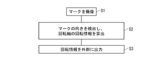
- FIG. 7 is a flowchart showing an example of the operation of the encoder device EC.
- the imaging unit 7 images the mark 4 including a plurality of lines 12 that are provided on the rotation shaft 3 of the driving unit 2 and change the direction by the rotation of the rotation shaft 3.
- the image processing unit 8 detects the direction of the mark 4 using the captured image and calculates the rotation information of the rotation shaft 3. For example, the image processing unit 8 detects position information of the rotation axis based on the plurality of lines 12.
- the image processing unit 8 outputs the calculated rotation information to the outside. Whether or not step S3 is performed is arbitrary.
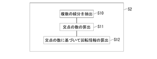
- FIG. 8 is a flowchart showing an example of the rotation information calculation process shown in step S2 of FIG.
- the image processing unit 8 determines the rotation axis 3 based on the number of intersection points P1 between the predetermined line segment 20 provided on the image Im and the images of the plurality of lines 12 as described in FIG. Calculate rotation information.
- step S ⁇ b> 10 the image processing unit 8 extracts a plurality of lines 12 from the image (for example, the image Im in FIG. 4) captured by the imaging unit 7.
- step S ⁇ b> 11 the image processing unit 8 calculates the number of intersection points P ⁇ b> 1 between the predetermined line segment 20 provided on the image Im and the images of the plurality of lines 12.
- the image processing unit 8 calculates the rotation information of the rotating shaft 3 based on the number of intersection points P1.
- FIG. 9 is a flowchart showing another example of the rotation information calculation process shown in step S2 of FIG.
- the image processing unit 8 calculates the angles ⁇ 1 to ⁇ 9 between the predetermined line segment 20 provided on the image Im and each of the images of the plurality of lines 12 as described with reference to FIG. The rotation information is calculated based on the value ⁇ m.
- the image processing unit 8 extracts a plurality of lines 12.
- the image processing unit 8 calculates angles ⁇ 1 to ⁇ 9 between the line 12 on the image Im and the predetermined 20 for each of the plurality of lines 12.
- step S ⁇ b> 14 the image processing unit 8 calculates an average value ⁇ m of images and angles of the predetermined line segment 20 and the plurality of lines 12 provided on the image Im. Further, the image processing unit 8 calculates the rotation information of the rotation shaft 3 based on the average value ⁇ m of the angles.
- the encoder device EC detects the orientation of the mark 4 using an image obtained by capturing the mark 4 and calculates the rotation information of the rotating shaft 3.
- the mark 4 can be easily formed as a marking line as described above. Further, even when the mark 4 (eg, the plurality of lines 12) is deviated from the rotation center O of the rotation shaft 3, the rotation information can be calculated with high accuracy. Further, in a normal encoder device, the scale is provided only in a part near the outer periphery of the rotating plate, and the scale reading accuracy may be reduced by downsizing the scale.
- the encoder device EC calculates the rotation information of the rotating shaft 3 based on the direction of the mark 4, for example, the line 12 can be arranged over a wide range of the end surface 10 of the rotating shaft 3, and a simple configuration Accordingly, it is possible to reduce the detection accuracy of the line 12 while reducing the size of the encoder device EC (mark 4).
- Encoder device EC may calculate rotation information other than the rotation position. For example, the encoder device EC may calculate at least one of the amount of change in the rotational position of the rotation shaft 3, the angular velocity, and the angular acceleration as the rotation information. Further, the encoder device EC may not calculate the rotational position of the rotary shaft 3 as the rotation information.
- FIG. 10A is a diagram showing a mark 4 according to the first modification.
- the mark 4 does not include the graphic 14.
- the mark 4 is missing one end of the line 12 d among the plurality of lines 12.
- the mark 4 has a non-axisymmetric shape with respect to the straight line L1 in which the plurality of lines 12 are perpendicular to the predetermined direction (X direction) and pass through the rotation center O of the rotation shaft 3.
- the mark 4 is axisymmetric with respect to at least one straight line passing through the center of the mark portion 5. Even if such a mark 4 is used, the image processing unit 8 can discriminate (polarity discrimination) between a state in which the amount of change in the rotational position is 0 ° and a state in which it is 180 °.
- FIG. 10B shows the mark 4 according to the second modification.
- the mark 4 has a distance d between the lines 12 and 12 in a part of the plurality of lines 12, and a line 12e and a line 12e in the other part ( ⁇ Y side). Is d1. d1 is set to a value different from d. Thus, the intervals between the plurality of lines 12 need not be equal. That is, the density of the plurality of lines 12 may not be constant.
- the mark 4 is non-axisymmetric with respect to a straight line L2 that is parallel to the plurality of lines 12 (parallel to the X direction) and passes through the rotation center O of the rotation shaft 3. It has become.
- the line 12e is densely arranged on the ⁇ Y side, and the line 12e is arranged on the + Y side in a state rotated 180 ° from the state of FIG. 10B. Even if such a mark 4 is used, the image processing unit 8 can discriminate (polarity discrimination) between a state in which the amount of change in the rotational position is 0 ° and a state in which it is 180 °.
- At least one of the plurality of lines 12 is formed with a thickness different from that of the other lines 12, or when the line 12 is formed as a groove, a dent, a recess, or a marking line,
- the image processing unit 8 can also discriminate (polarity discrimination) between a state where the amount of change in the rotational position is 0 ° and a state where it is 180 °.
- FIG. 11A is a diagram showing a mark 4 according to the third modification.
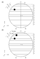
- the plurality of lines 12 include a broken line.
- FIG. 11B is a diagram showing a mark 4 according to a fourth modification.
- the plurality of lines 12 include a curve.
- the shape of line 12 is arbitrary and may be shapes other than a straight line (line segment).
- the plurality of lines 12 may not have the same shape.
- the plurality of lines 12 may be a combination of line segments, curved lines, and broken lines.
- the plurality of lines 12 may intersect one line with another line.
- At least one of the plurality of lines 12 may intersect with other lines at only one place, or may intersect with other lines (eg, broken lines, curves) at two or more places.
- at least one of the plurality of lines 12 includes, for example, at least one of a polygonal line portion and a curved portion, and may intersect with itself.
- the image processing unit 8 correlates the image Im of the mark 4 captured by the imaging unit 7 with the shape information such as a plurality of image data for each rotation position. The mark 4 may be calculated and detected from the image Im, and the direction of the mark 4 may be detected.
- FIG. 12A shows a mark 4 according to the fifth modification.
- the mark 4 includes a graphic 14.
- the figure 14 in FIG. 12A is a circle
- the shape of the figure 14 is arbitrary and may be a shape other than a circle, for example, a polygon such as a triangle, an ellipse, or the like, and the outline may be a line segment. And a shape including a curve (for example, a track shape).
- the figure 14 may be linear, or may be a line segment, a curve, or a shape (for example, a cross shape) in which at least one of the line segment and the curve is combined.
- the position of the figure 14 is arbitrary.
- the figure 14 may be in contact with the outer periphery of the mark part 5 as shown in FIG. It may not be in contact with the outer periphery.
- the image processing unit 8 can perform curve discrimination based on the graphic 14.
- FIG. 12B is a diagram showing the mark 4 according to the sixth modification.
- the mark 4 according to the sixth modification includes a plurality of figures 14 that are independent (discontinuous) from each other.
- the figure 14 includes, for example, a circular figure 14a and a rectangular figure 14b.
- the image processing unit 8 performs polarity determination based on at least one position of the graphic 14a and the graphic 14b.
- polarity determination can be performed based on information of other figures.
- the number of figures included in the figure 14 is arbitrary.
- the figure 14 may include three or more figures.
- FIG. 13 (A) is a view showing a mark portion 5 according to a seventh modification.
- the mark 4 has a non-symmetrical shape with respect to a straight line L1 that is perpendicular to the predetermined direction (X direction) and passes through the rotation center O of the rotation shaft 3.
- the mark 4 of this modification has a shape in which a part of the end surface 10 of the rotating shaft is cut off.
- part of the end face 10 in FIG. 13A is cut out in an arcuate shape, the cutout shape is not particularly limited.
- the mark 4 may have a shape in which the end face 10 itself is cut off, or may have a shape in which another member attached to the end face 10 as the mark portion 5 is cut off.
- the mark 4 includes, for example, a plurality of lines 12 parallel to the X direction. Since the notched portion of the mark 4 is out of the focusing position of the imaging optical system 17, it is easy to distinguish on the image captured by the imaging unit 7. As a result, the mark 4 has an asymmetric shape (for example, non-symmetrical with respect to the straight line L1), and thus the polarity can be determined using this asymmetry.
- the notch may be a V-shaped recess, for example.
- the plurality of lines 12 included in the mark 4 are grooves, dents, recesses, or marking lines
- the depth of the notch may be larger than the line depth
- the line width may be larger than the line width.
- the width of the notch may be larger.
- FIG. 13B is a diagram showing the mark portion 5 according to the eighth modification.
- the mark 4 is formed on the mark portion 5 attached to the end portion of the rotating shaft 3.
- the mark portion 5 is a disk-shaped member and is attached to the end surface 10 of the rotating shaft 3.
- the mark portion 5 may not be formed directly on the end face 10 as long as it is provided at the end portion of the rotating shaft 3.
- the mark portion 5 may be detachably formed on the end portion of the rotating shaft 3.
- the outer peripheral shape of the mark portion 5 may be a non-symmetrical shape with respect to a predetermined straight line L1 passing through the rotation center O of the rotation shaft 3, like the shape of the end face 10 of the seventh modification.
- FIG. 14 is a view showing a mark 4 according to the ninth modification.
- the mark 4 is provided on a disk attached to the end of the rotating shaft 3.
- the mark 4 may be provided at a position other than the end face 10 of the rotating shaft 3.
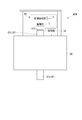
- FIG. 15A is a diagram illustrating an encoder device EC according to a tenth modification
- FIG. 15B is a diagram illustrating an example of an image Im2 captured by the imaging unit 7b.
- the encoder device EC includes a plurality of imaging units 7a and imaging units 7b, and images the mark 4 by each of the plurality of imaging units 7a and 7b.
- the encoder device EC includes, for example, a mark unit 5, an illumination unit 6, an imaging unit 7a, an imaging unit 7b, an image processing unit 8, and a storage unit 9.
- storage part 9 may be the same as that of above-described embodiment or each modification.
- the imaging unit 7 a images the entire area of the mark 4 formed on the mark unit 5.
- the visual field of the imaging unit 7a is set in advance in a range including the entire area of the mark 4, for example.
- the imaging unit 7 b images a part of the mark 4 formed on the mark unit 5.
- the field of view of the imaging unit 7b is set to a region R2 including only a part of the mark 4.
- the region R2 is set so as to include a region R1 that sandwiches a straight line L3 passing through the rotation center O of the mark 4.
- the imaging unit 7a and the imaging unit 7b are each arranged in the vicinity of the mark unit 5.
- the imaging unit 7a and the imaging unit 7b include an imaging optical system 17 and an imaging element 18, respectively.
- the imaging unit 7 a and the imaging unit 7 b each output captured image data to the image processing unit 8.
- the image processing unit 8 performs polarity determination using the image Im ⁇ b> 2 including only a part of the mark 4, and calculates the rotation information of the rotation shaft 3.
- the image processing unit 8 performs polarity determination by detecting the graphic 14 included in the image Im2.
- the encoder device EC may detect the rotation information of the rotation shaft 3 by imaging the mark 4 by using a plurality of imaging units (imaging unit 7a and imaging unit 7b).
- the imaging unit 7b may image the entire area of the mark 4.
- the encoder device EC may use the rotation information obtained from the image captured by the imaging unit 7b for interpolation, verification, backup, and the like of the rotation information obtained from the image captured by the imaging unit 7a.
- the number of the imaging units 7 may be three or more.
- the image used for polarity discrimination may have a lower resolution than the image used for detecting the rotational position.
- the polarity can be determined by using a photodetector that detects the brightness of a part of the region through which the figure 14 passes due to the rotation of the rotation shaft 3.
- the encoder device EC may include the photodetector described above instead of the imaging unit 7b.
- FIG. 16 is a diagram showing an encoder device EC according to the eleventh modification.
- the encoder device EC detects multi-rotation information using a processing unit different from the image processing unit 8.
- the encoder device EC includes, for example, a mark unit 5, an illumination unit 6, an imaging unit 7, an image processing unit 8, a storage unit 9, and a magnetic encoder unit 25.
- storage part 9 may be the same as that of the above-mentioned embodiment or each modification.
- the magnetic encoder unit 25 detects the rotation speed and rotation direction of the rotary shaft 3.
- the magnetic encoder unit 25 includes, for example, a magnet 26, a magnetic sensor 27, and a signal processing unit 28.
- the magnet 26 is provided on a disk 29 fixed to the rotating shaft 3. Since the disk 29 rotates together with the rotating shaft 3, the magnet 26 rotates along with the rotation of the rotating shaft 3 (with the rotating shaft 3).
- the magnetic sensor 27 includes, for example, a Hall element, and detects a change in the magnetic field accompanying the rotation of the magnet 26.
- the signal processing unit 28 detects the number of rotations and the rotation direction of the rotating shaft 3 using the detection result of the magnetic sensor 27.
- the signal processing unit 28 outputs the detected rotation speed and rotation direction of the rotating shaft 3 to the image processing unit 8.
- the image processing unit 8 uses the rotation number and rotation direction of the rotation shaft 3 detected by the signal processing unit 28 and the rotation position of the rotation shaft 3 obtained from the image captured by the imaging unit 7 (for example, combined) ), The multi-rotation information of the rotary shaft 3 is calculated.
- the image processing unit 8 combines the rotation information (eg, rotation position) obtained from the image captured by the imaging unit 7 and the rotation information (eg, rotation speed and rotation direction) detected by the signal processing unit 28.
- the combining unit may be provided separately from the image processing unit 8.
- the encoder device EC may detect the multi-rotation information using a processing unit different from the image processing unit 8, or detect the multi-rotation information by using the image processing unit and another processing unit in combination. May be.
- the processing unit for detecting the multi-rotation information may not be the magnetic encoder unit 25, and may be, for example, an optical rotary encoder.
- FIG. 17 is a diagram showing an encoder device EC according to a twelfth modification.
- the encoder device EC is a double encoder.
- the encoder device EC detects rotation information of the rotation shaft 3 and rotation information of the shaft whose rotation is adjusted with respect to the rotation shaft 3.
- the encoder device EC includes, for example, a mark unit 5, an illumination unit 6, an imaging unit 7, an image processing unit 8, a storage unit 9, and an encoder unit 32.
- storage part 9 may be the same as that of the above-mentioned embodiment or each modification.
- the encoder unit 32 is disposed in the vicinity of a shaft (not shown) whose rotation is adjusted by the transmission 31, and detects rotation information of this shaft.
- the encoder unit 32 may be, for example, a unit that detects the orientation of the mark as in the above-described embodiment, a rotary encoder that uses a scale, a magnetic encoder, or the like.
- the encoder unit 32 outputs the detected rotation information to the image processing unit 8.
- the image processing unit 8 calculates multi-rotation information of the rotating shaft 3 using the rotation information detected by the encoder unit 32 and the rotation position of the rotating shaft 3 detected by the image processing unit 8.
- the encoder device EC may perform polarity determination using the rotation information detected by the encoder unit 32. In this case, the image processing unit 8 does not perform polarity determination using the image captured by the imaging unit 7. May be.
- the mark 4 may not be provided in the encoder device EC.
- the mark 4 may be retrofitted to the rotating shaft 3.
- the illumination part 6 does not need to be provided in the encoder apparatus EC.
- the illumination unit 6 may be retrofitted, and the imaging unit 7 may capture a mark illuminated by light from a room light or natural light.
- the predetermined line segment 20 or the predetermined line segment 21 shown in FIGS. 5 and 6 may not be parallel to the horizontal scanning direction in the image Im.
- the predetermined line segment 20 or the predetermined line segment 21 may be inclined at an arbitrary angle with respect to the vertical scanning direction in the image Im.
- the predetermined line segment 20 or the predetermined line segment 21 may not be one, and the predetermined line segment 20 or the predetermined line segment 21 may be two or more.
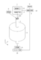
- FIG. 18 is a diagram illustrating an example of the driving device MTR.
- the drive device MTR is a motor device including an electric motor, for example.
- the driving device MTR controls the main body (driving unit) BD using the rotation information calculated by the main body (driving unit) BD that supplies driving force to the first axis AX1, the encoder device EC, and the image processing unit 8. And a control unit 34.
- the rotary shaft SF has a load side end SFa and an anti-load side end SFb.
- the load side end portion SFa is connected to another power transmission mechanism such as a speed reducer.
- the counter load side end portion SFb is provided with a mark portion 5 in which a mark 4 is formed.
- the encoder device EC may be any of the above-described embodiments, modified examples, or an encoder device that combines them.
- the encoder device EC includes, for example, an imaging unit 7 and an image processing unit 8.
- the imaging unit 7 images the mark 4.
- the image processing unit 8 detects the direction of the mark 4 using the image of the mark 4 captured by the imaging unit 7, calculates the rotation information of the rotation shaft 3, and detects the rotation position of the rotation shaft 3.
- the image processing unit 8 is connected to the control unit 34 and outputs the detection result to the control unit 34.
- the control unit 34 controls the main body (drive unit) BD using the detection result of the encoder device EC.
- the drive device MTR can operate with high accuracy because the encoder device EC can detect the rotation information of the rotary shaft 3 with high accuracy.
- the driving device MTR is not limited to the driving device, and may be another driving device having a shaft portion that rotates using hydraulic pressure or pneumatic pressure.
- FIG. 19 is a diagram showing a stage apparatus STG.
- This stage device STG has a configuration in which a rotary table (moving body) TB is attached to the load side end portion SFa of the rotary shaft SF of the drive device MTR shown in FIG.
- components that are the same as or equivalent to those in the above-described embodiment are denoted by the same reference numerals and description thereof is omitted or simplified.
- the stage device STG rotates the rotating shaft SF by driving the driving device MTR, this rotation is transmitted to the rotary table TB.
- the encoder device EC detects the angular position and the like of the rotating shaft SF. Therefore, the angular position of the rotary table TB can be detected by using the output from the encoder device EC.
- a reduction gear or the like may be disposed between the load side end SFa of the drive device MTR and the rotary table TB.
- the stage device STG can operate with high accuracy because the encoder device EC can detect the rotation information of the rotary shaft 3 with high accuracy.
- the stage apparatus STG can be applied to a rotary table provided in a machine tool such as a lathe.
- FIG. 20 is a perspective view showing the robot apparatus RBT.
- FIG. 20 schematically shows a part (joint portion) of the robot apparatus RBT.
- the robot apparatus RBT includes a first arm AR1, a second arm AR2, and a joint portion JT.
- the first arm AR1 is connected to the second arm AR2 via the joint portion JT.
- the first arm AR1 includes an arm portion 101, a bearing 101a, and a bearing 101b.
- the second arm AR2 has an arm portion 102 and a connection portion 102a.
- the connecting portion 102a is disposed between the bearing 101a and the bearing 101b in the joint portion JT.
- the connection part 102a is provided integrally with the rotation shaft SF.
- the rotation shaft SF is inserted into both the bearing 101a and the bearing 101b in the joint portion JT.
- the end of the rotating shaft SF on the side inserted into the bearing 101b passes through the bearing 101b and is connected to the speed reducer RG.
- the reducer RG is connected to the drive device MTR, and reduces the rotation of the drive device MTR to, for example, 1/100 and transmits it to the rotary shaft SF.
- the load side end portion SFa of the rotation shaft SF of the drive device MTR is connected to the speed reducer RG.
- a mark portion 5 on which the mark 4 of the encoder device EC is formed is provided on the anti-load side end portion SFb of the first axis AX1 of the drive device MTR.
- the robot apparatus RBT drives the driving apparatus MTR to rotate the first axis AX1
- this rotation is transmitted to the rotation axis SF via the reduction gear RG.
- the connecting portion 102a rotates integrally, whereby the second arm AR2 rotates relative to the first arm AR1.
- the encoder device EC detects the angular position and the like of the first axis AX1. Therefore, the angular position of the second arm AR2 can be detected by using the output from the encoder device EC.
- the robot apparatus RBT can operate with high accuracy because the encoder apparatus EC can detect the rotation information of the rotary shaft 3 with high accuracy.
- the robot apparatus RBT is not limited to the above configuration, and the drive apparatus MTR can be applied to various robot apparatuses having joints.
- EC encoder device, 2 ... drive unit (drive device), 3 ... rotation axis, 4 ... mark, 5 ... mark unit, 7, 7a, 7b ... imaging unit, 8 ⁇ ⁇ ⁇ Image processing unit, 9 ... Storage unit, 10 ... End face, 12, 12a-12e ... Line, 14, 14a-14c ... Graphic, 20, 21 ... Predetermined line, 34 ... Control unit, Im, Im2 ... Image, MTR ... Drive device, STG ... Stage device, RBT ... Robot device
Landscapes
- Physics & Mathematics (AREA)
- General Physics & Mathematics (AREA)
- Optical Transform (AREA)
- Length Measuring Devices By Optical Means (AREA)
Abstract
【課題】回転情報を精度よく取得可能なエンコーダ装置を提供する。 【解決手段】エンコーダ装置(EC)は、回転軸の回転により向きが変わる少なくとも一つの線を含むマーク(4)を撮像する撮像部(7)と、撮像部の撮像結果に基づくマークの向きを用いて、回転軸の回転情報を算出する処理部(8)と、を備える。
Description
本発明は、エンコーダ装置、駆動装置、ステージ装置、ロボット装置及び情報取得方法に関する。
回転情報を検出するエンコーダ装置は、駆動装置(例、モータ装置)などの各種装置に搭載されている。エンコーダ装置は、例えば、回転軸に設けられたスケールからの光を検出し、回転情報を取得する。また、エンコーダ装置として、スケールの代わりに偏光板を用いるものがある(例えば、下記特許文献1参照)。
回転軸の回転情報を高精度に求めたい場合、精密な光学パターンが正確に形成されたスケールが使用される。しかし、精密な光学パターンの形成は容易ではなく、製造コストも高くなるため、簡易な構成で、ある程度高精度に回転情報を求められるエンコーダも求められている。
本発明の第1の態様に従えば、回転軸の回転により向きが変わる少なくとも一つの線を含むマークを撮像する撮像部と、撮像部で得られた画像を用いて、回転軸の回転情報を算出する処理部と、を備えるエンコーダ装置が提供される。
本発明の第2の態様に従えば、第1の態様のエンコーダ装置と、回転軸に駆動力を供給する駆動部と、を備える駆動装置が提供される。
本発明の第3の態様に従えば、移動体と、移動体を移動させる第2の態様の駆動装置と、を備えるステージ装置が提供される。
本発明の第4の態様に従えば、第2の態様の駆動装置と、駆動装置によって相対移動するアームと、を備えるロボット装置が提供される。
本発明の第5の態様に従えば、駆動装置の回転軸に備えられ回転軸の回転により向きが変わる少なくとも一つの線を含むマークを撮像することと、撮像で得られた画像を用いてマークの向きを検出し、回転軸の回転情報を算出することと、を含む情報取得方法が提供される。
以下、本発明の実施形態について図面を参照しながら説明する。ただし、本発明はこれに限定されるものではない。また、図面においては実施形態を説明するため、一部分を大きくまたは強調して記載するなど適宜縮尺を変更して表現している。また、以下の各図に示すXYZ座標系を適宜用いて方向を説明する。X方向、Y方向及びZ方向のそれぞれは、適宜、図中の矢印の方向が+方向(例、+X方向)であり、その反対方向が-方向(-X方向)であるとする。
図1は、実施形態に係るエンコーダ装置ECの一例を示す図である。エンコーダ装置ECは、駆動部2の回転軸3の回転により向き(例、回転軸3に交差する面上での方向)が変わるマーク4を撮像する。また、エンコーダ装置ECは、マーク4を撮像して得られた画像を用いて、回転軸3の回転情報を算出する。エンコーダ装置ECは、マーク部5と、照明部6と、撮像部7と、画像処理部8と、を備える。なお、記憶部9はエンコーダ装置ECに備えられていてもよく、エンコーダ装置ECの装置外(例、外部装置)に備えられていてもよい。この場合、画像処理部8と外部の記憶部9とは、無線或いは有線などによって信号やデータ等の通信が可能なように構成される。また、マーク4と撮像部7とは回転軸の回転に伴って相対位置が変化すればよく、例えば、マーク4は非回転部に固定されており、回転軸3の回転に伴って撮像部7が回転してもよい。
駆動部2は、回転軸3を回転駆動する。駆動部2は、例えば、後に図18に示す駆動装置MTRの一部である。駆動部2は、例えば、電動モータであるが、電動モータでなくてもよい。駆動部2は、油圧や空圧を利用して回転する軸部を有する装置でもよい。回転軸3は、駆動部2の駆動力(トルク)により回転する。回転軸3は、駆動部2のシャフト(回転子)であるが、駆動部2のシャフトと接続される軸でもよい。回転軸3は、駆動部2のシャフトに接続される変速機などの動力伝達部内の軸でもよい。回転軸3は、駆動部2のシャフトに動力伝達部を介して接続される軸でもよい。回転軸3は、負荷に接続される軸でもよい。
一例として、マーク4は、回転軸3の端部に設けられたマーク部5に形成される。回転軸3の端部とは、回転軸3の端面とその付近をいう。マーク部5は、回転軸3の一部であってもよく、回転軸3の端部に取り付けられた別の部材であってもよい。マーク部5が回転軸3の一部である場合、マーク部5は回転軸3の端面又はその付近となり、マーク4は回転軸3に作りこまれることになる。
マーク部5が回転軸3と別の部材として設けられる場合、例えば、マーク部5は回転軸3の端面に取り付けることができる。
マーク部5は、回転軸3において負荷11に接続される側の反対側(反出力軸側)の端部に設けられる。マーク部5が反出力軸側に設けられる場合、負荷11などからの汚れ(例、油、オイルミストなど)がマーク部5に付着することが抑制される。マーク部5は回転軸3の回転方向や回転角度に応じて回転する。マーク部5は回転軸3と一体的に回転する。
マーク部5が回転軸3と別の部材として設けられる場合、例えば、マーク部5は回転軸3の端面に取り付けることができる。
マーク部5は、回転軸3において負荷11に接続される側の反対側(反出力軸側)の端部に設けられる。マーク部5が反出力軸側に設けられる場合、負荷11などからの汚れ(例、油、オイルミストなど)がマーク部5に付着することが抑制される。マーク部5は回転軸3の回転方向や回転角度に応じて回転する。マーク部5は回転軸3と一体的に回転する。
図2(A)はエンコーダ装置ECを+Z方向から見た平面図、(B)はマーク部5を示す図である。マーク部5には、回転軸3の回転により向きが変わるマーク4が形成される。マーク4は、マーク部3の回転位置を示すことが可能なパターンである。マーク4は、回転軸3の回転により、回転軸3に交差(例、直交、非直交)する面上での向き(例、方向)が変化する。マーク4は、少なくとも1つの線(例、複数の線12)を含む。マーク4は、例えば、直線(まっすぐな線、2点を結ぶ最短の線、線分)および曲線の少なくとも一方を1つ以上含む。マーク4の線は、例えば、長さ方向に対して有限の幅を有する帯状である。以下、有限の幅を有する帯状の図形を、便宜上、線(例、直線、曲線、線分)という。マーク4の少なくとも1つの線は、直線状の部分および曲線状の部分を含む線でもよい。マーク4の少なくとも1つの線は、折れ線状の部分を含む線でもよく、折れ線状の部分および曲線上の部分を含む線でもよい。複数の線12は、例えば、それぞれ線分であり、互いに平行に配置される。複数の線12は、回転軸3を基準として形成してもよい。例えば、複数の線12のうち少なくとも1つは回転軸3の中心を通るように形成されてもよく、複数の線12のいずれも回転軸3の中心を通らなくてもよい。複数の線12は、それぞれ、所定方向(例、X方向)に平行に配置され、所定方向の交差方向(例、Y方向、直交方向、非直交方向)に互いに離れて配置される。複数の線12のうち一本の線を基準線としたとき、残りの線は基準線に対して所定の距離を有する。線12の数は、任意の数に設定される。複数の線12は、それぞれ、回転軸3の端面10の外周上の2点を結ぶ線分であってもよい。複数の線12は、少なくともその一つの線12に対する交差方向(Y方向)に配列されてもよい。複数の線12は、等間隔で配列されてもよく、それぞれ異なる間隔で配列されてもよい。複数の線12の間隔dは、任意に設定される。なお、図2(B)には複数の線12が回転中心Oを通らない位置に配置される例を示すが、複数の線12の少なくとも1つが回転軸3の回転中心Oを通る位置に配置されてもよい。マーク4に含まれる線12の数は、任意であり、1つでもよいし、複数でもよい。マーク4に含まれる線の長さも任意であり、複数の線がある場合、すべて同じ長さとしてもよく、それぞれ異なる長さとしてもよい。例えば、マーク部が円形の場合、少なくとも一本の線の長さをマーク部の半径より長い長さとしてもよい。
マーク4は、回転軸3の回転中心Oを通る少なくとも一本の直線に関して非線対称としてもよい。また、マーク4は、回転軸3の回転中心Oを通るすべての直線に関して非線対称としてもよい。例えば、マーク4は、図形14を含み、図形14と複数の線12を組み合わせて、回転軸3の回転中心Oを通るあらゆる直線に対して非線対称とすることができる。図形14は、回転軸3の回転中心Oを通る直線(例えば直線L1)でマーク部5を分割してできる2つの領域R1の一方のみ(例、-X方向の領域R1のみ)に設けてもよい。図形14が設けられる領域と図形14が設けられない領域とは、回転軸の中心に対して点対称に位置してもよい。また、図形14が設けられる領域と図形14が設けられない領域とは、回転軸3の回転中心Oを通る直線L1に関して線対称に設けられてもよい。図形14は、後に図6などで説明するが、180°の回転(極性)を区別することに利用することができる。図形14は、例えば、複数の線12のいずれとも異なる形状である。図形14は、例えば、端面10の-X方向における外周の一部を含む弓型の形状である。例えば図形14は、回転軸3の中心軸方向視(マーク4を平面視した状態)において、回転軸3の回転方向(周方向)に広がりを持つ。図2(B)において、回転軸3の中心軸方向視において、複数の線12のうち任意に選択される一本の線を基準線12xとする。回転軸3の回転方向における図形14の一端E1と回転軸3の回転中心Oとを繋いだ直線OE1と基準線12xとの角度をγ1とし、回転軸3の回転方向における図形14の他端E2と回転軸3の回転中心Oとを繋いだ直線OE2と基準線12xとの角度をγ2としたときに、γ1とγ2は、0°<γ1<180°の関係と0°<γ2<180°の関係との一方または双方を満たしてもよい。
マーク4は、撮像部7が撮像した画像上で識別可能(他の部分と区別可能)に形成される。例えば、マーク4の線は、例えば、端面10に形成された(刻印された)ケガキ線である。マーク4の線12は、例えば、端面10に形成された(刻印された)溝や窪みや凹部であってもよく、またマーク4の線12が凸部や構造体であってもよい。なお、複数の線12が端面10に形成されたケガキ線である場合、複数の線12のうち少なくとも1つは、他の線12と線の深さが異なってもよいし、他の線12と線の太さが異なってもよい。マーク4の図形14は、例えば、端面10の表面を荒らしたものである。マーク部5は、例えば、回転軸3の一部であるが、回転軸3に取り付けられる部材(回転軸3と別の部材)でもよい(後に図13(B)で説明する)。なお、マーク4は、端面10に印刷などにより形成されたものでもよいし、端面10の一部に黒体化などの表面処理を施したものでもよい。また、マーク4は、端面10の一部分における光の反射率を他の部分よりも高くなるように、表面処理を施したものでもよい。マーク4は、マーク部5(例、端面10)の全域(例、全面)に形成されてもよいし、マーク部5(例、端面10)の一部のみに形成されてもよい。
図1の説明に戻り、照明部6は、マーク4を照明する。例えば、照明部6は、マーク部5の近傍に配置され、マーク4に光を照射する。照明部6は、例えば、チップ型の発光ダイオード(LED)等の固体光源を含む。照明部6は、発光ダイオード以外の固体光源(例、レーザダイオード)を含んでもよいし、ランプ光源を含んでもよい。
撮像部7は、マーク4を撮像する。撮像部7は、例えば、マーク部5の近傍に配置される。撮像部7は、例えば、端面10の法線方向(例、Z方向)からマーク4を撮像する。撮像部7は、マーク4が照明部6に照明されている状態で、マーク4を撮像してもよい。撮像部7は、例えば、結像光学系17と、撮像素子18と、を備える。結像光学系17は、レンズを有し、マーク4の像を形成する。撮像素子18は、結像光学系17が形成した像を撮像する。撮像素子18は、例えば、CCDイメージセンサやCMOSイメージセンサ等の固体撮像素子(二次元イメージセンサ)である。結像光学系17は、例えば、オートフォーカス機構を備え、撮像素子18は、結像光学系17の焦点位置がマーク4に合焦した状態で、マーク4を撮像する。撮像部7は、マーク4の撮像画像を生成する。
図3は、撮像部7により撮像される画像Im(撮像画像)の一例を示す図である。撮像部7は、例えば、マーク部5に形成されたマーク4の全域を撮像する。すなわち、撮像部7の視野は、マーク4の全域を含む範囲に予め設定してもよい。また、撮像部7の視野は、マーク4の全域を撮像する際、画像Imにおけるマーク4以外の部分が少なくなるように設定してもよい。例えば、撮像部7の視野中心は、回転軸3の回転中心Oまたはその近傍に設定される。なお、撮像部7は、マーク4の全域を撮像しなくてもよく、マーク4の一部を撮像してもよい。また、撮像部7は、マーク4を複数回に分けて撮像(例、スキャン)し、画像処理部8は、複数回の撮像で得られる複数の画像の2つ以上を合成した画像を用いて、回転情報を算出してもよい。
図1の説明に戻り、撮像部7は、画像処理部8と有線または無線により通信可能に接続され、撮像したマーク4の画像Imのデータを画像処理部8に供給(例、送信)する。画像処理部8は、撮像部7が撮像した画像Im(図3参照)を処理する。画像処理部8は、例えば、デジタル・シグナル・プロセッサ(DSP)、特定用途向けIC(ASIC)、プログラマブルロジックデバイス(programmable logic device: PLD)などを含む。記憶部9は、例えば、画像処理部8に接続され、各種データを記憶する。記憶部9には、撮像部7が撮像した画像Imのデータ、画像処理部8の処理中のデータ、画像処理部8の処理後のデータ、画像処理部8が処理に用いるデータ(例、設定値、パラメータ)などが記憶される。記憶部9は、例えば、RAM、フラッシュメモリ、ROM等を含む。
画像処理部8は、撮像部7で得られた画像を用いて、回転軸3の回転情報を算出する。例えば、画像処理部8は、撮像部7が撮像した画像Imを用いてマーク4の向きを検出、判定、あるいは導出し、回転軸3の回転情報を算出する。画像処理部8は、画像Imに写っている複数の線12に基づき、回転軸3の回転情報を検出する。回転情報は、回転軸3の回転に関する情報であり、例えば、回転軸3の回転位置(角度位置)、回転位置の変化量、角速度、及び角加速度の少なくとも1つを含む。回転軸3の回転位置は、基準の位置からの回転角であってもよい。回転情報は、回転数を区別しない情報(以下、単回転情報という)でもよいし、回転数を区別する情報(以下、多回転情報という)でもよい。単回転情報は、例えば回転位置の変化量が400°である場合、回転数(1回転、360°)を無視した40°という値で表され、回転位置の変化量が40°である場合と同じ値で表される。また、多回転情報は、例えば回転位置の変化量が400°である場合、400°あるいは1回転と40°という値で表される。回転情報は、例えば所定のビット数の2進数で表され、度(deg)に換算される値でもよいし、ラジアン(rad)に換算される値でもよい。
次に、画像処理部8による回転情報の算出処理について説明する。図4は、画像処理部8による回転情報の算出処理の一例を示す図である。画像処理部8は、例えば、画像Im上に画像処理によって設けた所定の線分20と、画像Im上の複数の線12の像との交点P1の数に基づいて、回転軸3の回転情報を算出する。例えば、画像処理部8は、撮像部7が撮像した画像Imを2値化し、2値化した画像から、エッジ検出やハフ変換等の処理により複数の線12を抽出する。画像処理部8は、例えば、抽出した複数の線12を、画像Im上の水平走査方向の座標と垂直走査方向の座標との関係を示す一次式で表す。続いて、画像処理部8は、画像Im上の所定の線分20と複数の線12との交点P1の数を算出する。ここでは、所定の線分20が水平走査方向に対して平行であるとして説明するが、所定の線分20は、水平走査線と非平行でもよいし、垂直走査線に平行でもよく、水平走査線および垂直走査線のいずれとも非平行でもよい。所定の線分20の長さLは、任意に設定されるが、例えば、複数の線12の配列方向(例、線12に垂直な方向)において一端に配置された線12aから他端に配置された線12bまでの幅B以上に設定される。
画像Im上での交点P1の座標は、例えば、画像Im上の線12の像を表す一次式と所定の線分20を表す一次式との連立方程式の解くことで、得られる。また、交点P1の数は、複数の線12のそれぞれについて、マーク4の範囲内で所定の線分20と交点P1を持つか否かを判定し、交点P1の数を計数することで求められる。ここで、図4に示す所定の線分20と、複数の線12のうち1つの線12cとの角度をφとし、複数の線12の間隔をdとし、交点P1と交点P1との間隔をXとすると、これらの関係は、下記の式(1)で表される。なお、式(1)において、||は、絶対値を表す。
X=|d/sinφ| ・・・(1)
X=|d/sinφ| ・・・(1)
また、交点P1の個数Nは、例えば、L/Xの整数部(長さLの所定の線20の区間に収まる線12の間隔の数)をINT(L/X)とすると、下記の式(2)で表される。式(2)にN、d及びLを代入することにより、所定の線分20と複数の線12との角度φを算出することができる。
N=INT(L/X)+1=INT(|Lsinφ|/d)+1 ・・・(2)
例えば、N=100の場合、L/Xは99以上100未満であり、画像処理部8は、その中間値99.5をL/Xの値として角度φを算出することができる。角度φは、複数の線12(マーク4)の向きを表す情報である。このように画像処理部8は、複数の線12に基づき角度φを算出することにより、マーク4の向きを検出し、回転軸3の回転情報を算出する。
N=INT(L/X)+1=INT(|Lsinφ|/d)+1 ・・・(2)
例えば、N=100の場合、L/Xは99以上100未満であり、画像処理部8は、その中間値99.5をL/Xの値として角度φを算出することができる。角度φは、複数の線12(マーク4)の向きを表す情報である。このように画像処理部8は、複数の線12に基づき角度φを算出することにより、マーク4の向きを検出し、回転軸3の回転情報を算出する。
図5は、画像処理部8による回転情報の算出処理の他の例を示す図である。マーク4における複数の線12が互いに平行に配置される場合、画像処理部8は、例えば、画像Im上に設けた所定の線分21と、画像Im上の複数の線12の像のそれぞれとの角度θ1~θ9を求め、角度の平均値θmに基づいて回転情報を算出する。画像処理部8は、例えば、図4を参照して説明したのと同様に、マーク4の画像を2値化して複数の線12を抽出し、抽出した複数の線12をそれぞれ画像Im上の座標の一次式で表す。所定の線分21は、例えば、画像Im上の水平走査方向に対して平行に設定される。この場合、複数の線12のそれぞれを表した一次式の傾きから、θ1~θ9が算出可能である。画像処理部8は、例えば、角度θ1~θ9の平均値θmを、回転軸3の回転情報として算出する。平均値θmは、例えば、相加平均でもよいし、相乗平均でもよく、加重平均(重み付け平均)でもよい。角度θ1~θ9の検出精度は、一般的に複数の線12のうち長い線12ほど高く、加重平均の重み付け係数は、線12の長さに比例する量でもよい。このように画像処理部8は、複数の線12に基づき角度θmを算出することにより、マーク4の向きを検出し、回転軸3の回転情報を算出してもよい。このように、複数の線12のそれぞれの像と、画像上に設けた所定の線分21との角度(例、角度θ1~θ9)を平均化する場合、例えば、マーク4(例、端面10)の汚れやキズなどの影響を低減することができ、回転情報を精度よく取得可能である。なお、汚れや傷などがマーク部に存在する場合予め処理部においてノイズとして除去してもよい。線分の一部に汚れや傷が存在する場合には、その線分は角度検出に使用しなくてもよく、汚れや傷がある部分の情報を補間してもよい。
なお、画像処理部8による回転情報の算出処理は、図4、図5の例に限らない。例えば、画像処理部8は、マーク4の形状情報(例、参照情報)を記憶部9から取得し、当該形状情報と、画像Im上のマーク4の像から回転情報を算出してもよい。形状情報は、例えば、回転軸3が所定の回転位置である場合の画像を予め作成したものとすることができる。例えば、形状情報は、0度~360度までの所定の角度ごとのマーク4の画像データでもよい。この画像データは、撮像部7で撮像した画像でもよいし、この画像を加工したものでもよい。また、この画像データは、撮像部7を用いないで取得した画像データでもよく、例えば画像作成ソフトウェアなどで生成した画像データでもよい。画像処理部8は、例えば、撮像部7で撮像されたマーク4の画像Imと、上記した画像データ等の形状情報との相関を算出し、画像Imから回転軸の回転情報を算出することができる。
また、画像処理部8は、マーク4の画像Imと、各回転位置に応じた上記の形状情報(例、画像データ)とを記憶部9から取得し、画像Imと形状情報との比較により、回転情報を算出してもよい。例えば、画像処理部8は、各回転位置に応じた形状情報と画像Imとの相関係数を算出し、相関係数が最大になる形状情報に対応する回転位置を、回転軸3の回転位置としてもよい。また、画像処理部8は、各回転位置に応じた形状情報と画像Imとの相関係数を用いて、回転軸3の回転位置を算出してもよい。例えば、画像処理部8は、まず、各回転位置に応じた形状情報として、所定の角度ごとの画像データを用いて相関係数を算出し、次いで、相関係数が高い上位2つの画像データに対応する回転位置の区間における区間中の位置を、相関係数を用いて算出してもよい。
また、画像処理部8は、上記した相関係数の算出を、段階的に行ってもよい。例えば、画像処理部8は、まず、各回転位置に応じた形状情報として、角度の刻み幅が粗い複数の画像データを用いて相関係数を算出し、次いで、相関係数が高い上位2つの画像データに対応する回転位置の区間について、角度の刻み幅が細かい複数の画像データを用いて、回転軸3の回転位置を算出してもよい。
また、画像処理部8は、各回転位置に応じた形状情報と画像Imとをパターンマッチングすることにより、回転軸3の回転位置を算出してもよい。例えば、画像処理部8は、まず、各回転位置に応じた形状情報として、所定の角度ごとの画像データを用いてパターンマッチングを行い、パターンマッチが最大になる形状情報に対応する回転位置を、回転軸3の回転位置としてもよい。なお、画像Imと画像データとの比較(例、相関係数の算出、パターンマッチング)は、マーク4全体で行ってもよいし、マーク4の一部に対して行ってもよい。例えば、画像Imと画像データとの比較は、マーク4における複数の線12全部に対して行ってもよいし、複数の線12の一部に対して行ってもよい。
なお、画像処理部8は、回転情報として、回転軸3の回転位置以外の情報を算出してもよいし、回転軸3の回転位置を算出しなくてもよい。例えば、画像処理部8は、回転情報として、回転数、回転位置の変化量、回転方向、回転速度(例、角速度)、回転加速度(例、角加速度)及び回転軸3の偏心情報(例、偏心誤差、偏芯角度)の少なくとも1つを算出してもよい。例えば、画像処理部8は、回転位置の変化量を算出し、その正負(回転軸3の位置が変化する方向)を判別することにより、回転方向を算出してもよい。また、画像処理部8は、回転方向を区別した回転位置の変化量を積算することにより、回転方向を加味した回転数を算出してもよい。例えば、画像処理部8は、回転軸3の回転位置の変化量の積算値が360°を超えたときに回転数を+1カウントし、-360°を下回ったときに回転数を-1カウントすることにより、回転数を算出することができる。また、画像処理部8は、例えば、回転数や回転方向の情報を使って、回転軸3の多回転情報を算出することができる。また、画像処理部8は、例えば、各時刻におけるマーク4の画像Imの回転中心Oを検出し、回転中心Oの軌跡を検出し、検出した回転中心Oの軌跡データを使って、回転軸3の偏心を算出してもよい。
次に、回転の極性判別について説明する。一般的に、エンコーダ装置は、回転位置の変化量が0°である状態と180°である状態とを区別しにくい。例えば、回転軸が180°回転する周波数と比較してサンプリング周波数が小さい場合、回転位置の変化量が0°である状態と180°である状態とを区別できない場合がある。
本実施形態に係るエンコーダ装置ECは、図2に示したように、マーク4が回転中心Oを通る直線L1に関して非線対称な形状であり、この非対称性を利用して、回転位置の変化量が0°である状態と180°である状態との区別(極性判別)を行う。例えば、マーク4は、回転中心を通る直線L1を挟む一対の領域R1の一方のみに図形14が設けられることにより、直線L1に関して非線対称である。
図6は、撮像部7に撮像されたマーク4の画像Imを、回転軸3の回転位置と対応付けて示す図である。撮像部7は、例えば、回転軸3が回転している間、マーク部5を所定の間隔(例、サンプリング周期)で撮像する。図6には、回転軸3の回転位置が0°、45°、90°、135°、280°、225°、270°、315°及び360°におけるマーク4を、撮像部7が撮像した画像Imを示した。ここでは説明の便宜上、マーク4の複数の線12がX方向(水平走査方向)に平行である場合を、回転軸3の回転位置の基準(例、0°)とする。
画像処理部8は、例えば、図形14を検出することにより、回転位置がα°の状態と回転位置が(α+180)°の状態とを区別する。例えば、画像処理部8は、複数の線12と画像Imの水平走査線との角度が0°である場合(回転位置が0°、180°)、画像Im上の図形14が、回転中心Oを通り垂直走査線に平行な線Cyに対していずれの側にあるかを判定する。画像処理部8は、例えば、図形14が線Cyの左側にある場合に回転位置が0°であると判定し、図形14が線Cyの右側にある場合に回転位置が180°であると判定する。また、例えば、画像処理部8は、複数の線12と画像Imの水平走査線との角度が90°である場合(回転位置が90°、270°)、画像Im上の図形14が、回転中心Oを通り水平走査線に平行な線Cxに対していずれの側にあるかを判定する。画像処理部8は、例えば、図形14が線Cxの上側にある場合に回転位置が90°であると判定し、図形14が線Cxの下側にある場合に回転位置が270°であると判定する。
なお、画像処理部8は、例えば画像Im上で回転中心Oを原点とする直交座標系において、図形14が第1象限~第4象限のいずれに位置するかを判定することにより、極性判別を行ってもよい。このように、図形14を極性判別に用いる場合、図形14と複数の線12とで形状が異なっていると、図形14を複数の線12から区別することが容易である。また、図形14を用いないで極性判別を行ってもよく(後に図10等で説明する)、この場合、マーク4は図形14を含まなくてもよい。また、エンコーダ装置ECは、マーク4を用いないで極性判別を行ってもよい。例えば、エンコーダ装置ECは、回転軸3が180°回転する周波数と比較してサンプリング周波数が小さく設定され、回転軸3の回転位置の変化量を積算して、極性判別を行ってもよい。また、エンコーダ装置ECは、磁気式エンコーダ(後に図16に示す)あるいはダブルエンコーダ(後に図17に示す)などにより、極性判別を行ってもよい。
画像処理部8は、以上のように算出した回転軸3の回転情報を外部に出力する。画像処理部8は、例えば、回転情報を高速双方向シリアル通信により外部へ送信する。例えば、画像処理部8は、回転軸3の回転情報を、駆動部2を制御する制御部(例、後に図18に示す制御部34)に出力する。この制御部34は、回転軸3の回転情報を使うことにより、駆動部2を精度よく制御することができる。
次に、上述のようなエンコーダ装置ECの動作に基づき、情報取得方法について説明する。図7は、エンコーダ装置ECの動作の一例を示すフローチャートである。ステップS1において、撮像部7は、駆動部2の回転軸3に備えられ回転軸3の回転により向きが変わる複数の線12を含むマーク4を撮像する。ステップS2において、画像処理部8は、撮像された画像を用いてマーク4の向きを検出し、回転軸3の回転情報を算出する。例えば、画像処理部8は、複数の線12に基づき回転軸の位置情報を検出する。ステップS3において、画像処理部8は、算出した回転情報を外部に出力する。なお、ステップS3を行うか否かは任意である。
図8は、図7のステップS2に示した回転情報の算出処理の一例を示すフローチャートである。本例において、画像処理部8は、図4で説明したように画像Im上に設けた所定の線分20と、複数の線12の像との交点P1の数に基づいて、回転軸3の回転情報を算出する。ステップS10において、画像処理部8は、撮像部7が撮像した画像(例、図4の画像Im)から、複数の線12を抽出する。ステップS11において、画像処理部8は、画像Im上に設けた所定の線分20と、複数の線12の像との交点P1の数を算出する。ステップS12において、画像処理部8は、交点P1の数に基づいて、回転軸3の回転情報を算出する。
図9は、図7のステップS2に示した回転情報の算出処理の他の例を示すフローチャートである。本例において、画像処理部8は、図5で説明したように画像Im上に設けた所定の線分20と複数の線12の像のそれぞれとの角度θ1~θ9を算出し、角度の平均値θmに基づいて回転情報を算出する。ステップS10において、画像処理部8は、複数の線12を抽出する。ステップS13において、画像処理部8は、複数の線12のそれぞれについて、画像Im上の線12と所定の20との角度θ1~θ9を算出する。ステップS14において、画像処理部8は、画像Im上に設けた所定の線分20と複数の線12の像と角度の平均値θmを算出する。また、画像処理部8は、角度の平均値θmに基づいて回転軸3の回転情報を算出する。
上述のように、本実施形態に係るエンコーダ装置ECは、マーク4を撮像した画像を用いてマーク4の向きを検出し、回転軸3の回転情報を算出する。このマーク4は、上述のようにケガキ線などとして簡易に形成できる。また、マーク4(例、複数の線12)が回転軸3の回転中心Oからずれている場合でも、回転情報を精度よく算出することができる。また、通常のエンコーダ装置は、スケールが回転板の外周付近の一部のみに設けられ、スケールを小型化によりスケールの読み取り精度が低下することがある。本実施形態に係るエンコーダ装置ECは、マーク4の向きにより回転軸3の回転情報を算出するので、例えば、回転軸3の端面10の広い範囲にわたって線12を配置することができ、簡易な構成によって、エンコーダ装置EC(マーク4)の小型化を図りつつ、線12の検出精度の低下をおさえることもできる。
エンコーダ装置ECは、回転位置以外の回転情報を算出してもよい。例えば、エンコーダ装置ECは、回転情報として、回転軸3の回転位置の変化量、角速度、及び角加速度の少なくとも1つを算出してもよい。また、エンコーダ装置ECは、回転情報として、回転軸3の回転位置を算出しなくてもよい。
[変形例]
次に、変形例について説明する。本変形例において、上記の実施形態と対応関係にある要素については、同じ符号を付してその説明を省略あるいは簡略化する。図10(A)は、第1変形例に係るマーク4を示す図である。第1変形例において、マーク4は、図形14を含まない。マーク4は、複数の線12のうち、線12dの一端が欠けている。これにより、マーク4は、複数の線12が所定方向(X方向)に垂直かつ回転軸3の回転中心Oを通る直線L1に関して、非線対称な形状となる。さらに、マーク4は、マーク部5の中心を通る少なくとも一本の直線に関して非線対称である。このようなマーク4を用いても、画像処理部8は、回転位置の変化量が0°の状態と180°の状態とを判別(極性判別)することができる。
次に、変形例について説明する。本変形例において、上記の実施形態と対応関係にある要素については、同じ符号を付してその説明を省略あるいは簡略化する。図10(A)は、第1変形例に係るマーク4を示す図である。第1変形例において、マーク4は、図形14を含まない。マーク4は、複数の線12のうち、線12dの一端が欠けている。これにより、マーク4は、複数の線12が所定方向(X方向)に垂直かつ回転軸3の回転中心Oを通る直線L1に関して、非線対称な形状となる。さらに、マーク4は、マーク部5の中心を通る少なくとも一本の直線に関して非線対称である。このようなマーク4を用いても、画像処理部8は、回転位置の変化量が0°の状態と180°の状態とを判別(極性判別)することができる。
図10(B)は、第2変形例に係るマーク4を示す図である。第2変形例において、マーク4は、複数の線12のうちの一部において、線12と線12との間隔がdであり、他の部分(-Y側)において、線12eと線12eとの間隔がd1である。d1は、dと異なる値に設定される。このように、複数の線12の間隔は等間隔でなくてもよい。つまり、複数の線12の粗密は一定でなくてもよい。複数の線12をこのように配置することにより、マーク4は、複数の線12に対して平行(X方向に平行)かつ回転軸3の回転中心Oを通る直線L2に関して、非線対称な形状となっている。図10(B)のマーク4は、-Y側において線12eが密に配置されており、図10(B)の状態から180°回転した状態において、線12eが+Y側に配置される。このようなマーク4を用いても、画像処理部8は、回転位置の変化量が0°の状態と180°の状態とを判別(極性判別)することができる。また、複数の線12のうち少なくとも1つ線を他の線12と異なる太さで形成することや、線12が溝や窪みや凹部やケガキ線として形成される場合に他の線12と線の異なる深さで形成することによっても、画像処理部8は、回転位置の変化量が0°の状態と180°の状態とを判別(極性判別)することができる。
図11(A)は、第3変形例に係るマーク4を示す図である。第3変形例において、複数の線12は折れ線を含む。図11(B)は、第4変形例に係るマーク4を示す図である。第4変形例において、複数の線12は曲線を含む。第3変形例及び第4変形例のように、線12の形状は任意であり、直線(線分)以外の形状でもよい。また、複数の線12は、それぞれの線12が同一の形状でなくてもよい。例えば、複数の線12は、線分、曲線、折れ線を併用したものでもよい。複数の線12は、その1つの線が他の線と交差してもよい。例えば、複数の線12の少なくとも1つの線は、他の線と1カ所のみで交差してもよいし、他の線(例、折れ線、曲線)と2カ所以上で交差してもよい。また、複数の線12の少なくとも1つは、例えば折れ線状の部分と曲線状の部分の少なくとも一方を含み、自身と交差してもよい。複数の線12が折れ線や曲線を含む場合、例えば、画像処理部8は、撮像部7で撮像されたマーク4の画像Imと、回転位置ごとの複数の画像データ等の形状情報との相関を算出し、画像Imからマーク4を検出し、マーク4の向きを検出してもよい。
図12(A)は、第5変形例に係るマーク4を示す図である。第5変形例において、マーク4は図形14を含む。図12(A)における図形14は円形であるが、図形14の形状は、任意であり、円形以外の形状、例えば、三角形などの多角形状でもよいし、楕円形などでもよく、輪郭が線分と曲線とを含む形状(例、トラック状)でもよい。また、図形14は、線状でもよく、線分、曲線、線分と曲線の少なくとも一方を組み合わせた形状(例、十字状)でもよい。また、図形14の位置は任意であり、例えば、図形14は、図2(B)に示したようにマーク部5の外周に接していてもよいし、本変形例のようにマーク部5の外周に接していなくてもよい。画像処理部8は、図形14に基づいて曲線判別を行うことができる。
図12(B)は、第6変形例に係るマーク4を示す図である。第6変形例に係るマーク4は、互いに独立した(不連続な)複数の図形14を含む。図形14は、例えば、円形の図形14aと、矩形状の図形14bとを含む。画像処理部8は、例えば、図形14aと図形14bとの少なくとも一方の位置に基づいて極性判別を行う。このように図形14が複数であると、複数の図形14のうち一つの図形に汚れが付いた場合においても、他の図形の情報に基づいて極性判別を行うことができる。なお、図形14に含まれる図形の数は任意であり、例えば、図形14は3つ以上の図形を含んでもよい。
図13(A)は、第7変形例に係るマーク部5を示す図である。第7変形例において、マーク4は、所定方向(X方向)に垂直かつ回転軸3の回転中心Oを通る直線L1に関して、非線対称な形状である。本変形例のマーク4は、回転軸の端面10の一部が切り取られた形状となっている。図13(a)の端面10は、一部が弓型形状に切り欠かれているが、切り欠かれる形状は特に限定されない。マーク4は、端面10自体が切り取られた形状であってもよく、端面10にマーク部5として取り付けた別の部材が切り取られた形状であってもよい。マーク4は、例えば、X方向に平行な複数の線12を含む。マーク4の切り欠かれた部分は、結像光学系17の合焦位置から外れるため、撮像部7が撮像した画像上で区別しやすい。これにより、マーク4は、非対称な形状(例、直線L1に関して非線対称)になるため、この非対称性を利用して極性判別を行うことができる。切り欠き部は、例えばV字型のくぼみでもよい。マーク4に含まれる複数の線12が溝や窪みや凹部やケガキ線である場合には、線の深さよりも切り欠き部の深さの方が大きくてもよく、また、線の幅よりも切り欠き部の幅の方が大きくてもよい。
図13(B)は、第8変形例に係るマーク部5を示す図である。第8変形例において、マーク4は、回転軸3の端部に取り付けられたマーク部5に形成される。例えば、マーク部5は、円板状の部材であり、回転軸3の端面10に取り付けられる。マーク部5は、回転軸3の端部に設けられるものであれば、端面10に直接形成されなくてもよい。例えば、マーク部5は、回転軸3の端部に着脱可能に形成されてもよい。また、マーク部5の外周形状は、第7変形例の端面10の形状のように、回転軸3の回転中心Oを通る所定の直線L1に対して、非線対称な形状でもよい。
図14は、第9変形例に係るマーク4を示す図である。第9変形例において、マーク4は、回転軸3の端部に取り付けられた円板に備えられる。このように、マーク4は、回転軸3の端面10以外の位置に設けられてもよい。
図15(A)は、第10変形例に係るエンコーダ装置ECを示す図であり、(B)は、撮像部7bにより撮像された画像Im2の一例を示す図である。第10変形例において、エンコーダ装置ECは、複数の撮像部7aと撮像部7bとを備え、複数の撮像部7a及び撮像部7bのそれぞれによりマーク4を撮像する。エンコーダ装置ECは、例えば、マーク部5と、照明部6と、撮像部7aと、撮像部7bと、画像処理部8と、記憶部9と、を備える。なお、マーク部5、照明部6、画像処理部8及び記憶部9は、上記した実施形態、又は各変形例と同様でよい。
撮像部7aは、マーク部5に形成されたマーク4の全域を撮像する。撮像部7aの視野は、例えば、マーク4の全域を含む範囲に予め設定される。撮像部7bは、マーク部5に形成されたマーク4の一部分を撮像する。撮像部7bの視野は、例えば、マーク4の一部分のみを含む領域R2に設定される。この領域R2は、例えば、図15(b)に示すように、マーク4の回転中心Oを通る直線L3を挟む領域R1を含むように設定される。撮像部7a及び撮像部7bは、それぞれ、マーク部5の近傍に配置される。撮像部7a及び撮像部7bは、それぞれ、結像光学系17と撮像素子18を備える。撮像部7a及び撮像部7bは、それぞれ、撮像した画像のデータを画像処理部8に出力する。画像処理部8は、例えば、マーク4の一部分のみを含む画像Im2を用いて極性判別を行い、回転軸3の回転情報を算出する。画像処理部8は、例えば、画像Im2に含まれる図形14を検出することにより、極性判別を行う。
このように、エンコーダ装置ECは、複数の撮像部(撮像部7a及び撮像部7b)により、マーク4を撮像し、回転軸3の回転情報を検出してもよい。なお、撮像部7bは、マーク4の全域を撮像してもよい。例えば、エンコーダ装置ECは、撮像部7bが撮像した画像から得られる回転情報を、撮像部7aが撮像した画像から得られる回転情報の補間、検証、バックアップなどに利用してもよい。また、撮像部7の数は、3つ以上でもよい。ところで、極性判別に用いられる画像は、回転位置の検出に用いられる画像よりも解像度が低くてもよい。例えば、回転軸3の回転により図形14が通る領域の一部の明暗を検出する光検出器を用いて、極性判別をすることもできる。例えば、エンコーダ装置ECは、撮像部7bの代わりに上記の光検出器を備えてもよい。
図16は、第11変形例に係るエンコーダ装置ECを示す図である。第11変形例において、エンコーダ装置ECは、画像処理部8と異なる処理部を用いて多回転情報を検出する。このエンコーダ装置ECは、例えば、マーク部5と、照明部6と、撮像部7と、画像処理部8と、記憶部9と、磁気式エンコーダ部25を備える。なお、マーク部5、照明部6、撮像部7、画像処理部8及び記憶部9は、上記した実施形態、又は各変形例のものと同様でよい。
磁気式エンコーダ部25は、回転軸3の回転数及び回転方向を検出する。磁気式エンコーダ部25は、例えば、磁石26、磁気センサ27、及び信号処理部28を備える。磁石26は、回転軸3に固定された円板29に設けられる。円板29は回転軸3とともに回転するため、磁石26は回転軸3の回転に伴って(回転軸3に同伴して)回転する。磁気センサ27は、例えばホール素子を含み、磁石26の回転に伴う磁界の変化を検出する。信号処理部28は、磁気センサ27の検出結果を用いて、回転軸3の回転数及び回転方向を検出する。信号処理部28は、検出した回転軸3の回転数及び回転方向を画像処理部8に出力する。画像処理部8は、信号処理部28が検出した回転軸3の回転数及び回転方向と、撮像部7が撮像した画像から得られる回転軸3の回転位置とを使って(例、合成して)、回転軸3の多回転情報を算出する。ここでは、画像処理部8は、撮像部7が撮像した画像から得られる回転情報(例、回転位置)と、信号処理部28が検出した回転情報(例、回転数及び回転方向)とを合成する合成部を兼ねるが、合成部は画像処理部8と別に設けられてもよい。このように、エンコーダ装置ECは、画像処理部8と異なる処理部を用いて多回転情報を検出してもよいし、画像処理部と他の処理部とを併用して多回転情報を検出してもよい。多回転情報を検出する処理部は、磁気式エンコーダ部25でなくてもよく、例えば、光学式のロータリエンコーダでもよい。
図17は、第12変形例に係るエンコーダ装置ECを示す図である。第12変形例において、エンコーダ装置ECは、ダブルエンコーダである。エンコーダ装置ECは、回転軸3の回転情報と、回転軸3に対して回転が調整された軸の回転情報とを検出する。エンコーダ装置ECは、例えば、マーク部5と、照明部6と、撮像部7と、画像処理部8と、記憶部9と、エンコーダ部32と、を備える。なお、マーク部5、照明部6、撮像部7、画像処理部8及び記憶部9は、上記した実施形態、又は各変形例のものと同様でよい。
エンコーダ部32は、変速機31により回転が調整される軸(不図示)の近傍に配置され、この軸の回転情報を検出する。エンコーダ部32は、例えば、上述の実施形態のようにマークの向きを検出するものでもよいし、スケールを用いたロータリエンコーダなどでもよく、磁気式エンコーダなどでもよい。エンコーダ部32は、例えば、検出した回転情報を画像処理部8に出力する。画像処理部8は、エンコーダ部32が検出した回転情報と、画像処理部8で検出した回転軸3の回転位置とを使って、回転軸3の多回転情報を算出する。なお、エンコーダ装置ECは、エンコーダ部32が検出した回転情報を用いて極性判別を行ってもよく、この場合、画像処理部8は、撮像部7が撮像した画像を用いた極性判別を行わなくてもよい。
マーク4は、エンコーダ装置ECに備えられなくてもよい。例えば、マーク4は、回転軸3に後付されるものでもよい。また、照明部6は、エンコーダ装置ECに備えられなくてもよい。例えば、照明部6は、後付されるものでもよいし、撮像部7は、室内灯からの光や自然光などに照らされたマークを撮像してもよい。
図5及び図6に示した所定の線分20あるいは所定の線分21は、画像Imにおける水平走査方向に対して平行でなくてもよい。例えば、所定の線分20あるいは所定の線分21は、画像Imにおける垂直走査方向に対して任意の角度で傾斜したものでもよい。また、所定の線分20あるいは所定の線分21は1つでなくてもよく、所定の線分20あるいは所定の線分21は、2つ以上でもよい。
[駆動装置]
次に、駆動装置について説明する。図18は、駆動装置MTRの一例を示す図である。以下の説明において、上記した実施形態と同一または同等の構成部分については同一符号を付けて説明を省略または簡略化する。駆動装置MTRは、例えば、電動モータを含むモータ装置である。駆動装置MTRは、第1軸AX1に駆動力を供給する本体部(駆動部)BDと、エンコーダ装置ECと、画像処理部8が算出した回転情報を使って本体部(駆動部)BDを制御する制御部34と、を備える。
次に、駆動装置について説明する。図18は、駆動装置MTRの一例を示す図である。以下の説明において、上記した実施形態と同一または同等の構成部分については同一符号を付けて説明を省略または簡略化する。駆動装置MTRは、例えば、電動モータを含むモータ装置である。駆動装置MTRは、第1軸AX1に駆動力を供給する本体部(駆動部)BDと、エンコーダ装置ECと、画像処理部8が算出した回転情報を使って本体部(駆動部)BDを制御する制御部34と、を備える。
回転軸SFは、負荷側端部SFaと、反負荷側端部SFbとを有する。負荷側端部SFaは、減速機など他の動力伝達機構に接続される。反負荷側端部SFbには、マーク4が形成されたマーク部5が設けられる。エンコーダ装置ECは、上述した実施形態、変形例、あるいはそれらを組み合わせたエンコーダ装置のいずれでもよい。エンコーダ装置ECは、例えば、撮像部7と、画像処理部8とを備える。撮像部7は、マーク4を撮像する。画像処理部8は、撮像部7が撮像したマーク4の画像を使って、マーク4の向きを検出し、回転軸3の回転情報を算出し、回転軸3の回転位置を検出する。画像処理部8は、制御部34と接続され、検出結果を制御部34に出力する。
この駆動装置MTRは、エンコーダ装置ECの検出結果を使って、制御部34が本体部(駆動部)BDを制御する。駆動装置MTRは、エンコーダ装置ECが回転軸3の回転情報を精度よく検出することができるので、精度よく動作することができる。なお、駆動装置MTRは、駆動装置に限定されず、油圧や空圧を利用して回転する軸部を有する他の駆動装置であってもよい。
[ステージ装置]
次に、ステージ装置について説明する。図19は、ステージ装置STGを示す図である。このステージ装置STGは、図18に示した駆動装置MTRの回転軸SFのうち負荷側端部SFaに、回転テーブル(移動体)TBを取り付けた構成である。以下の説明において、上記した実施形態と同一または同等の構成部分については同一符号を付けて説明を省略または簡略化する。
次に、ステージ装置について説明する。図19は、ステージ装置STGを示す図である。このステージ装置STGは、図18に示した駆動装置MTRの回転軸SFのうち負荷側端部SFaに、回転テーブル(移動体)TBを取り付けた構成である。以下の説明において、上記した実施形態と同一または同等の構成部分については同一符号を付けて説明を省略または簡略化する。
ステージ装置STGは、駆動装置MTRを駆動して回転軸SFを回転させると、この回転が回転テーブルTBに伝達される。その際、エンコーダ装置ECは、回転軸SFの角度位置等を検出する。従って、エンコーダ装置ECからの出力を用いることにより、回転テーブルTBの角度位置を検出することができる。なお、駆動装置MTRの負荷側端部SFaと回転テーブルTBとの間に減速機等が配置されてもよい。
このようにステージ装置STGは、エンコーダ装置ECが回転軸3の回転情報を精度よく検出することができるので、精度よく動作することができる。なお、ステージ装置STGは、例えば、旋盤等の工作機械に備える回転テーブル等に適用できる。
[ロボット装置]
次に、ロボット装置について説明する。図20は、ロボット装置RBTを示す斜視図である。なお、図20には、ロボット装置RBTの一部(関節部分)を模式的に示した。以下の説明において、上記した実施形態と同一または同等の構成部分については同一符号を付けて説明を省略または簡略化する。このロボット装置RBTは、第1アームAR1と、第2アームAR2と、関節部JTとを有している。第1アームAR1は、関節部JTを介して、第2アームAR2と接続されている。
次に、ロボット装置について説明する。図20は、ロボット装置RBTを示す斜視図である。なお、図20には、ロボット装置RBTの一部(関節部分)を模式的に示した。以下の説明において、上記した実施形態と同一または同等の構成部分については同一符号を付けて説明を省略または簡略化する。このロボット装置RBTは、第1アームAR1と、第2アームAR2と、関節部JTとを有している。第1アームAR1は、関節部JTを介して、第2アームAR2と接続されている。
第1アームAR1は、腕部101、軸受101a、及び軸受101bを備えている。第2アームAR2は、腕部102および接続部102aを有する。接続部102aは、関節部JTにおいて、軸受101aと軸受101bの間に配置されている。接続部102aは、回転軸SFと一体的に設けられている。回転軸SFは、関節部JTにおいて、軸受101aと軸受101bの両方に挿入されている。回転軸SFのうち軸受101bに挿入される側の端部は、軸受101bを貫通して減速機RGに接続されている。
減速機RGは、駆動装置MTRに接続されており、駆動装置MTRの回転を例えば100分の1等に減速して回転軸SFに伝達する。図20に図示しないが、駆動装置MTRの回転軸SFのうち負荷側端部SFaは、減速機RGに接続されている。また、図20に図示しないが、駆動装置MTRの第1軸AX1のうち反負荷側端部SFbには、エンコーダ
装置ECのマーク4が形成されたマーク部5が設けられている。
装置ECのマーク4が形成されたマーク部5が設けられている。
ロボット装置RBTは、駆動装置MTRを駆動して第1軸AX1を回転させると、この回転が減速機RGを介して回転軸SFに伝達される。回転軸SFの回転により接続部102aが一体的に回転し、これにより第2アームAR2が、第1アームAR1に対して回転する。その際、エンコーダ装置ECは、第1軸AX1の角度位置等を検出する。従って、エンコーダ装置ECからの出力を用いることにより、第2アームAR2の角度位置を検出することができる。
このようにロボット装置RBTは、エンコーダ装置ECが回転軸3の回転情報を精度よく検出することができるので、精度よく動作することができる。なお、ロボット装置RBTは、上記の構成に限定されず、駆動装置MTRは、関節を備える各種ロボット装置に適用できる。
なお、本発明の技術範囲は、上述の実施形態などで説明した態様に限定されるものではない。上述の実施形態などで説明した要件の1つ以上は、省略されることがある。また、上述の実施形態などで説明した要件は、適宜組み合わせることができる。また、法令で許容される限りにおいて、上述の実施形態などで引用した全ての文献の開示を援用して本文の記載の一部とする。
EC・・・エンコーダ装置、2・・・駆動部(駆動装置)、3・・・回転軸、4・・・マーク、5・・・マーク部、7、7a、7b・・・撮像部、8・・・画像処理部、9・・・記憶部、10・・・端面、12、12a~12e・・・線、14、14a~14c・・・図形、20、21・・・所定の線、34・・・制御部、Im、Im2・・・画像、MTR・・・駆動装置、STG・・・ステージ装置、RBT・・・ロボット装置
Claims (20)
- 回転軸の回転により向きが変わる少なくとも一つの線を含むマークを撮像する撮像部と、
前記撮像部で得られた画像を用いて、前記回転軸の回転情報を算出する画像処理部と、を備えるエンコーダ装置。 - 前記マークは、前記回転軸の端部のマーク部に形成されている、請求項1に記載のエンコーダ装置。
- 前記マークは、前記回転軸に固定された円板に形成されている、請求項1に記載のエンコーダ装置。
- 前記画像処理部は、前記画像における前記少なくとも一つの線の像と、前記画像上に設けた所定の直線との関係に基づいて、前記回転軸の回転情報を算出する、請求項1から請求項3のいずれか一項に記載のエンコーダ装置。
- 前記マークは、平行な複数の線を含む、
請求項1から請求項4のいずれか一項に記載のエンコーダ装置。 - 前記平行な複数の線は、平行な複数の直線、平行な複数の曲線、又は平行な複数の折れ線である、請求項5に記載のエンコーダ装置。
- 前記平行な複数の線は、等間隔に配置されている、請求項5又は請求項6に記載のエンコーダ。
- 前記画像処理部は、前記画像における前記平行な複数の線の像と、前記画像上に設けた所定の線との交点の数に基づいて、前記回転軸の回転情報を算出する、
請求項5から請求項7のいずれか一項に記載のエンコーダ装置。 - 前記画像処理部は、前記画像における前記平行な複数の線の像のそれぞれと、前記画像上に設けた所定の線とがなす角度を算出し、前記角度の平均値に基づいて、前記回転軸の回転情報を算出する、
請求項5から請求項7のいずれか一項に記載のエンコーダ装置。 - 前記マークは、前記マーク部の中心を通る少なくとも一本の直線に関して非線対称な形状である、
請求項2に記載のエンコーダ装置。 - 前記マークは、前記マーク部の中心を通る直線で前記マーク部を分割してできる2つの領域の一方のみに設けられる図形を含む、
請求項2に記載のエンコーダ装置。 - 前記マークは、前記円板の中心を通る少なくとも一本の直線に関して非線対称な形状である、
請求項3に記載のエンコーダ装置。 - 前記マークは、前記円板の中心を通る直線で前記マークを分割してできる2つの領域の一方のみに設けられる図形を含む、
請求項3に記載のエンコーダ装置。 - 前記撮像部は、前記マークの全域を撮像する、
請求項1から請求項13のいずれか一項に記載のエンコーダ装置。 - 前記撮像部を2以上含み、
前記画像処理部において、少なくとも一つの撮像部で得られた画像を用いて、前記マークの極性判別を行う、
請求項1から14のいずれか一項に記載のエンコーダ装置。 - 前記少なくとも一つの線は、ケガキ線として形成されている、請求項1から請求項15のいずれか一項に記載のエンコーダ装置。
- 請求項1から請求項16のいずれか一項に記載のエンコーダ装置と、
前記回転軸に駆動力を供給する駆動部と、
を備える駆動装置。 - 移動体と、
前記移動体を移動させる請求項17に記載の駆動装置と、を備えるステージ装置。 - 請求項17に記載の駆動装置と、
前記駆動装置によって移動するアームと、を備えるロボット装置。 - 回転軸の回転により向きが変わる少なくとも一つの線を含むマークを撮像することと、
前記撮像して得られた画像を用いて、前記回転軸の回転情報を算出することと、を含む情報取得方法。
Priority Applications (1)
| Application Number | Priority Date | Filing Date | Title |
|---|---|---|---|
| JP2017529580A JP6962194B2 (ja) | 2015-07-17 | 2016-07-14 | エンコーダ装置、駆動装置、ステージ装置、ロボット装置及び情報取得方法 |
Applications Claiming Priority (2)
| Application Number | Priority Date | Filing Date | Title |
|---|---|---|---|
| JP2015-142824 | 2015-07-17 | ||
| JP2015142824 | 2015-07-17 |
Publications (1)
| Publication Number | Publication Date |
|---|---|
| WO2017014142A1 true WO2017014142A1 (ja) | 2017-01-26 |
Family
ID=57833946
Family Applications (1)
| Application Number | Title | Priority Date | Filing Date |
|---|---|---|---|
| PCT/JP2016/070820 Ceased WO2017014142A1 (ja) | 2015-07-17 | 2016-07-14 | エンコーダ装置、駆動装置、ステージ装置、ロボット装置及び情報取得方法 |
Country Status (2)
| Country | Link |
|---|---|
| JP (1) | JP6962194B2 (ja) |
| WO (1) | WO2017014142A1 (ja) |
Cited By (6)
| Publication number | Priority date | Publication date | Assignee | Title |
|---|---|---|---|---|
| WO2018186317A1 (ja) * | 2017-04-03 | 2018-10-11 | ミネベアミツミ株式会社 | ロータリエンコーダ、回転量を特定する方法 |
| CN108789362A (zh) * | 2017-04-27 | 2018-11-13 | 精工爱普生株式会社 | 机器人及打印机 |
| CN111376013A (zh) * | 2018-12-29 | 2020-07-07 | 上海安浦鸣志自动化设备有限公司 | 一种编码器码盘全自动安装实现方法及设备 |
| JP2024044889A (ja) * | 2022-09-21 | 2024-04-02 | 株式会社 日立産業制御ソリューションズ | 検査装置、および、検査方法 |
| JP7598355B2 (ja) | 2022-12-20 | 2024-12-11 | 達明 鴨居 | 回転動作検出システム |
| WO2025070238A1 (ja) * | 2023-09-27 | 2025-04-03 | 川崎重工業株式会社 | 異常検知システム、方法および記憶媒体 |
Citations (5)
| Publication number | Priority date | Publication date | Assignee | Title |
|---|---|---|---|---|
| JPH10281811A (ja) * | 1997-04-10 | 1998-10-23 | Ricoh Co Ltd | ロータリエンコーダ |
| JP2000136944A (ja) * | 1998-10-30 | 2000-05-16 | Sony Corp | 回転角度測定装置 |
| WO2011074103A1 (ja) * | 2009-12-17 | 2011-06-23 | キヤノン株式会社 | ロータリエンコーダ及びそれを有する回転機構 |
| JP2013127435A (ja) * | 2011-12-19 | 2013-06-27 | Topcon Corp | 回転角検出装置及び測量装置 |
| JP2015105829A (ja) * | 2013-11-28 | 2015-06-08 | 株式会社ニコン | エンコーダ用スケール、エンコーダ、駆動装置、及びステージ装置 |
Family Cites Families (2)
| Publication number | Priority date | Publication date | Assignee | Title |
|---|---|---|---|---|
| JP2008151803A (ja) * | 2008-02-06 | 2008-07-03 | Ntn Corp | 回転検出装置および回転検出装置付き軸受 |
| EP2372302A1 (de) * | 2010-03-26 | 2011-10-05 | Leica Geosystems AG | Messverfahren für eine oberflächenvermessende Messmaschine |
-
2016
- 2016-07-14 JP JP2017529580A patent/JP6962194B2/ja active Active
- 2016-07-14 WO PCT/JP2016/070820 patent/WO2017014142A1/ja not_active Ceased
Patent Citations (5)
| Publication number | Priority date | Publication date | Assignee | Title |
|---|---|---|---|---|
| JPH10281811A (ja) * | 1997-04-10 | 1998-10-23 | Ricoh Co Ltd | ロータリエンコーダ |
| JP2000136944A (ja) * | 1998-10-30 | 2000-05-16 | Sony Corp | 回転角度測定装置 |
| WO2011074103A1 (ja) * | 2009-12-17 | 2011-06-23 | キヤノン株式会社 | ロータリエンコーダ及びそれを有する回転機構 |
| JP2013127435A (ja) * | 2011-12-19 | 2013-06-27 | Topcon Corp | 回転角検出装置及び測量装置 |
| JP2015105829A (ja) * | 2013-11-28 | 2015-06-08 | 株式会社ニコン | エンコーダ用スケール、エンコーダ、駆動装置、及びステージ装置 |
Cited By (11)
| Publication number | Priority date | Publication date | Assignee | Title |
|---|---|---|---|---|
| WO2018186317A1 (ja) * | 2017-04-03 | 2018-10-11 | ミネベアミツミ株式会社 | ロータリエンコーダ、回転量を特定する方法 |
| JP2018179532A (ja) * | 2017-04-03 | 2018-11-15 | ミネベアミツミ株式会社 | ロータリエンコーダ、回転量を特定する方法 |
| CN110494717A (zh) * | 2017-04-03 | 2019-11-22 | 美蓓亚三美株式会社 | 旋转编码器及确定旋转量的方法 |
| CN110494717B (zh) * | 2017-04-03 | 2022-05-17 | 美蓓亚三美株式会社 | 旋转编码器及确定旋转量的方法 |
| CN108789362A (zh) * | 2017-04-27 | 2018-11-13 | 精工爱普生株式会社 | 机器人及打印机 |
| JP2018185251A (ja) * | 2017-04-27 | 2018-11-22 | セイコーエプソン株式会社 | ロボットおよびプリンター |
| CN108789362B (zh) * | 2017-04-27 | 2023-03-14 | 精工爱普生株式会社 | 机器人及打印机 |
| CN111376013A (zh) * | 2018-12-29 | 2020-07-07 | 上海安浦鸣志自动化设备有限公司 | 一种编码器码盘全自动安装实现方法及设备 |
| JP2024044889A (ja) * | 2022-09-21 | 2024-04-02 | 株式会社 日立産業制御ソリューションズ | 検査装置、および、検査方法 |
| JP7598355B2 (ja) | 2022-12-20 | 2024-12-11 | 達明 鴨居 | 回転動作検出システム |
| WO2025070238A1 (ja) * | 2023-09-27 | 2025-04-03 | 川崎重工業株式会社 | 異常検知システム、方法および記憶媒体 |
Also Published As
| Publication number | Publication date |
|---|---|
| JPWO2017014142A1 (ja) | 2018-04-26 |
| JP6962194B2 (ja) | 2021-11-05 |
Similar Documents
| Publication | Publication Date | Title |
|---|---|---|
| JP6962194B2 (ja) | エンコーダ装置、駆動装置、ステージ装置、ロボット装置及び情報取得方法 | |
| US9879976B2 (en) | Articulated arm coordinate measurement machine that uses a 2D camera to determine 3D coordinates of smoothly continuous edge features | |
| US9628775B2 (en) | Articulated arm coordinate measurement machine having a 2D camera and method of obtaining 3D representations | |
| US10189137B2 (en) | Tool shape measuring apparatus | |
| US20170102224A1 (en) | Articulated arm coordinate measurement machine having a 2d camera and method of obtaining 3d representations | |
| US10585418B2 (en) | Control system of machine tool | |
| CN105486695A (zh) | 孔检测装置 | |
| JP2015006694A5 (ja) | ||
| JP7185510B2 (ja) | 中心検出方法 | |
| JP2021193400A (ja) | アーチファクトを測定するための方法 | |
| JPWO2017014189A1 (ja) | エンコーダ装置、駆動装置、ステージ装置、ロボット装置、回転情報取得方法及び回転情報取得プログラム | |
| AU2014310841A1 (en) | Optical tracking | |
| JP6809245B2 (ja) | ロボット | |
| US11933638B2 (en) | Method for detecting phase on gear, method for producing gear, method for detecting position on edge of workpiece, and machine tool for detecting phase on gear | |
| JP6710243B2 (ja) | 工具形状測定装置 | |
| JP4967775B2 (ja) | 玉軸受のボール位相検出方法 | |
| JP6858402B2 (ja) | 刃先情報取得装置および刃先情報取得方法 | |
| TW202408719A (zh) | 工具機及管理系統 | |
| JP6343312B2 (ja) | 溝入れ工具の刃幅計測方法 | |
| JP4061265B2 (ja) | 突起の高さ測定方法および測定装置 | |
| JP7332645B2 (ja) | 工具の形状異常検出装置、工具の形状異常検出方法 | |
| EP3385661B1 (en) | Articulated arm coordinate measurement machine that uses a 2d camera to determine 3d coordinates of smoothly continuous edge features | |
| JP6252437B2 (ja) | 回転角検出装置 | |
| Szydłowski et al. | Illumination for chatter mark detection using machine vision | |
| WO2020012757A1 (ja) | 測定装置 |
Legal Events
| Date | Code | Title | Description |
|---|---|---|---|
| 121 | Ep: the epo has been informed by wipo that ep was designated in this application |
Ref document number: 16827702 Country of ref document: EP Kind code of ref document: A1 |
|
| ENP | Entry into the national phase |
Ref document number: 2017529580 Country of ref document: JP Kind code of ref document: A |
|
| NENP | Non-entry into the national phase |
Ref country code: DE |
|
| 122 | Ep: pct application non-entry in european phase |
Ref document number: 16827702 Country of ref document: EP Kind code of ref document: A1 |