WO2017013922A1 - 非接触環状シール及びこれを備える回転機械 - Google Patents
非接触環状シール及びこれを備える回転機械 Download PDFInfo
- Publication number
- WO2017013922A1 WO2017013922A1 PCT/JP2016/063530 JP2016063530W WO2017013922A1 WO 2017013922 A1 WO2017013922 A1 WO 2017013922A1 JP 2016063530 W JP2016063530 W JP 2016063530W WO 2017013922 A1 WO2017013922 A1 WO 2017013922A1
- Authority
- WO
- WIPO (PCT)
- Prior art keywords
- seal
- annular seal
- contact annular
- thread groove
- fixed body
- Prior art date
- Legal status (The legal status is an assumption and is not a legal conclusion. Google has not performed a legal analysis and makes no representation as to the accuracy of the status listed.)
- Ceased
Links
Images











Classifications
-
- F—MECHANICAL ENGINEERING; LIGHTING; HEATING; WEAPONS; BLASTING
- F16—ENGINEERING ELEMENTS AND UNITS; GENERAL MEASURES FOR PRODUCING AND MAINTAINING EFFECTIVE FUNCTIONING OF MACHINES OR INSTALLATIONS; THERMAL INSULATION IN GENERAL
- F16J—PISTONS; CYLINDERS; SEALINGS
- F16J15/00—Sealings
- F16J15/44—Free-space packings
- F16J15/447—Labyrinth packings
Definitions
- the present invention relates to a non-contact annular seal and a rotary machine including the same, and in particular, in a rotary machine that handles an incompressible fluid, the amount of fluid leakage between an impeller and a casing and a casing is reduced and vibration is reduced.
- the present invention relates to a non-contact annular seal that exhibits stable shaft seal characteristics and a rotary machine including the same.
- Rotating machines that transfer liquids are widely used in plants or facilities for power generation, chemical processes, sewerage, waterworks, and the like.
- the pump has a casing and a rotating shaft on which an impeller is mounted.
- a rotating shaft is arrange
- the liquid sucked from the suction port of the casing is pressurized by the rotation of the impeller and discharged from the discharge port of the casing. That is, in the flow path inside the pump, a high pressure region and a low pressure region are formed, and fluid flows from the high pressure region to the low pressure region.
- the non-contacting annular seal is used in the part circled in the figure. That is, it is used between the inlet part of the impeller, between the front stage impeller and the rear stage impeller, between the last stage impeller outlet part and the low pressure side (pump inlet pressure), and the like.
- the differential pressure is large between the impeller outlet and the low pressure side, and fluid leakage is large, the fluid leakage at this portion has a great influence on the pump performance. For this reason, non-contact annular seals of various structures that can reduce the amount of fluid leakage are known.
- the smooth seal is known as the most basic non-contact annular seal.
- the smooth seal is a seal formed by arranging double cylinders having smooth surfaces.
- a non-contact annular seal such as a smooth seal
- it is effective to reduce the radial gap between the rotating side and the stationary side of the non-contact annular seal.
- the radial gap cannot be made extremely small.
- a non-contact annular seal that reduces the leakage amount without reducing the radial gap is required.
- a parallel groove seal, a damper seal, a thread groove seal and the like are known.
- an example of a conventional non-contact annular seal will be described.
- FIG. 18 is a partial sectional view of a conventional parallel groove seal.
- the parallel groove seal 111 includes a rotating shaft 121 that is a rotating body having a smooth outer peripheral surface, and a fixed body 131 in which a plurality of concentric grooves 141 are provided on a surface facing the rotating shaft 121.
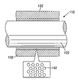
- This parallel groove seal 111 has energy loss due to vortices generated when the fluid flowing through the gap between the rotating shaft 121 and the fixed body 131 passes through the groove 141, pressure loss caused by sudden expansion and contraction of the flow path, and the like. Thus, the leakage amount (movement amount) of the fluid can be reduced.
- FIG. 19 and 20 are partial cross-sectional views of a conventional damper seal.
- FIG. 19 shows a damper seal that employs a honeycomb pattern as a damper structure.
- the fixed body 132 is shown in a sectional view
- the rotating shaft 122 is shown in a side view.
- the damper seal 112 includes a rotating shaft 122 that is a rotating body having a smooth outer peripheral surface, and a fixed body 132 having a plurality of concave portions 142 provided on a surface facing the rotating shaft 122.
- a hexagonal honeycomb pattern is used as the recess 142.
- the damper seal 112 can reduce the amount of fluid leakage due to the pressure loss of the fluid generated when the fluid flowing through the gap between the rotating shaft 122 and the fixed body 132 flows through the recess 142.
- FIG. 20 shows a damper seal that employs a hole pattern as a damper structure.
- the fixed body 133 is shown in a sectional view
- the rotating shaft 123 is shown in a side view.
- the damper seal 113 includes a rotating shaft 123 that is a rotating body having a smooth outer peripheral surface, and a fixed body 133 that is provided with a plurality of recesses 143 on a surface facing the rotating shaft 123.
- a circular concave hole pattern is used as the concave portion 143.
- the damper seal 113 can reduce the amount of fluid leakage due to the pressure loss of the fluid that occurs when the fluid flowing through the gap between the rotating shaft 123 and the fixed body 133 flows through the recess 143.
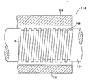
- FIG. 21 is a partial cross-sectional view of a conventional thread groove seal.
- the fixed body 134 is shown in a sectional view
- the rotating shaft 124 is shown in a side view.
- the thread groove seal 114 includes a cylindrical fixed body 134 having a smooth inner peripheral surface, and a rotating shaft 124 having a thread groove 144 formed on a surface facing the fixed body 134.
- the thread groove seal 114 has an effect of pushing back the fluid to the high pressure side by a pumping effect according to the rotation direction, and reducing the amount of leakage.
- the thread groove 144 is a continuous groove from the seal inlet side (high pressure side) to the seal outlet side (low pressure side).
- the pressure difference between the inlet side and the outlet side of the thread groove seal 114 is large, the leakage flow due to the pressure difference becomes large. Therefore, it is often possible to reduce the leakage amount by reducing the lead angle.
- Patent Document 1 A non-contact annular seal used in a fluid machine such as a turbo molecular pump is disclosed in Japanese Utility Model Publication No. 62-98798 (Patent Document 1).
- the fluid passing through the inside of the seal swirls around the outer periphery of the rotating shaft, so that unstable vibration (also referred to as self-excited vibration) occurs in the rotating shaft, and an abnormal vibration state occurs in the rotating shaft. May occur.
- unstable vibration also referred to as self-excited vibration
- an abnormal vibration state occurs in the rotating shaft. May occur.
- the difficulty of generating this unstable vibration is one of the important characteristics of the non-contact annular seal. It has been found that this unstable vibration is more likely to occur as the swirl flow in the circumferential direction of the rotation shaft inside the seal increases.
- the thread groove seal which has a thread groove in a fixed body is often used as a means to suppress unstable vibration. It has been found that the effect of suppressing unstable vibration due to the screw groove provided in the fixed body is more remarkable as the lead angle of the screw groove is larger. However, as described above, when the lead angle of the thread groove is increased, the amount of leakage often increases, and it can be said that there is a trade-off relationship between the effect of suppressing unstable vibration and the effect of reducing the amount of leakage. Therefore, it has been difficult to achieve both a reduction in leakage and suppression of unstable vibration at a high level.
- the present invention has been made in view of the above-described conventional problems, and one of its purposes is to improve the effect of suppressing unstable vibration caused by the swirling flow in the circumferential direction of the rotating shaft, while improving the effect of suppressing the inside of the seal. Is to suppress an increase in the amount of fluid leaking through the fluid.
- Another object of the present invention is to reduce the leakage of the fluid pressurized by the impeller to the low pressure side in a rotary machine that rotates the rotating shaft to which the impeller is attached and transfers the fluid. It is to suppress the unstable vibration caused by the fluid passing through the inside of the seal while increasing the efficiency.
- the rotating body includes a rotating body provided in a rotating portion of the rotating machine and a fixing body provided in a fixing portion of the rotating machine, and flows through a gap between the rotating body and the fixing body.
- a non-contact annular seal configured to seal fluid is provided.
- the non-contact annular seal has a thread groove provided on at least one of the surface of the rotating body and the surface of the fixed body forming the gap, and the thread groove is a plane orthogonal to the axial direction of the rotating body.
- the lead angle of the screw groove with respect to the seal is defined, and the lead angle of the screw groove on the seal inlet side is larger than the lead angle of the screw groove on the seal outlet side.
- the lead angle of the thread groove is relatively increased on the high pressure side (seal inlet side) that has a large effect of suppressing the destabilizing vibration, the effect of suppressing the destabilizing vibration is improved. be able to.
- the lead angle of the thread groove is relatively small on the low pressure side (seal outlet side), an increase in the amount of fluid leaking through the seal can be suppressed. Therefore, according to one aspect of the present invention, it is possible to achieve both the effect of suppressing unstable vibration of the non-contact annular seal and high shaft sealing performance.
- the thread groove has a lead angle of the thread groove that gradually decreases from the seal inlet side toward the seal outlet side. It is formed.
- the non-contact annular seal can be manufactured by joining together a plurality of non-contact annular seals having thread grooves with different lead angles. For this reason, the said non-contact annular seal can be easily manufactured, for example using the non-contact annular seal which exists conventionally.
- the thread groove in the one form of the non-contact annular seal, has a lead angle of the thread groove that continuously decreases from the seal inlet side toward the seal outlet side. It is formed. According to this, the lead angle of the thread groove can be finely set to an appropriate angle according to the axial position. As a result, the effect of suppressing the unstable vibration of the non-contact annular seal and the shaft sealing performance can be further improved.
- the depth of the thread groove on the seal inlet side is greater than the depth of the thread groove on the seal outlet side.
- the lead angle of a thread groove having a predetermined number of threads in the non-contact annular seal is increased, the width of the thread groove has to be increased, and the sum of the cross-sectional areas of the thread grooves is increased.
- the lead angle of the thread groove having a predetermined width is increased, the number of strips must be increased, and the sum total of the cross-sectional areas of the thread grooves is increased.
- the total cross-sectional area of the thread grooves of the non-contact annular seal can be reduced, so that the amount of fluid leaking between the seals can be further reduced.
- the thread groove is formed at least on the surface of the fixed body.
- the thread groove is formed at least on the surface of the fixed body.
- the thread groove is formed on the surface of the fixed body, even if the thread groove is formed on the surface of the rotating body, the swirling of the fluid caused by the rotation of the rotating body is caused by the thread groove on the surface of the fixed body. Can be suppressed. In this case, the amount of fluid leakage can be further reduced by the pumping effect of the thread groove formed on the surface of the rotating body. Therefore, when the thread groove is formed on both the fixed body and the rotating body, the amount of leakage can be further suppressed while suppressing unstable vibration.
- a rotating machine includes an electric motor, a main shaft connected to the electric motor and configured to be rotatable, an impeller that is fitted to the main shaft and configured to be rotatable together with the main shaft, and a casing that houses the impeller. And a bearing attached to the casing and rotatably supporting the main shaft, the main shaft has a rotating portion, the casing has a fixing portion, and the rotating portion and the fixing portion are It has a non-contact annular seal.
- the fluid boosted by the impeller is prevented from leaking to the low pressure side, thereby improving pump efficiency.
- the unstable vibration caused by the fluid passing through the inside of the seal can be suppressed while increasing.
- FIG. 2 is an enlarged sectional view of a first stage impeller of the high pressure pump shown in FIG. 1. It is a fragmentary sectional view which shows the non-contact annular seal of this embodiment applicable to the non-contact annular seal shown in FIG. It is a figure which shows the other example of the cross-sectional shape of the screw groove formed in a fixing body. It is a figure which shows the other example of the cross-sectional shape of the screw groove formed in a fixing body. It is a figure which shows the other example of the cross-sectional shape of the screw groove formed in a fixing body. It is a figure which shows the other example of the cross-sectional shape of the screw groove formed in a fixing body.
- FIG. 1 shows a cross-sectional view of a high-pressure pump (multistage centrifugal pump) to which a non-contact annular seal according to this embodiment can be applied.
- the high-pressure pump 1 includes a main shaft 11 that is connected to an electric motor (not shown) and rotates, impellers 21a, 21b, and 21c fitted to the main shaft 11, a casing 31 that houses the impellers 21a, 21b, and 21c, and a casing. And bearings 45a and 45b attached to 31.
- the bearings 45a and 45b support the main shaft 11 to be rotatable.
- An electric motor (not shown) for rotationally driving the high-pressure pump 1 is connected to the main shaft 11 via a coupling 13 fitted to the left end of the main shaft 11.
- the casing 31 has a suction port 33 for sucking incompressible fluid such as water (hereinafter simply referred to as fluid) from the outside, and a discharge port 37 for discharging the sucked fluid.
- the first stage impeller 21 a fitted to the main shaft 11 rotates as the main shaft 11 rotates, and sucks fluid into the casing 31 from the suction port 33.
- the fluid sucked and pressurized by the first stage impeller 21a passes through the first flow path 35a and reaches the second stage impeller 21b.
- the fluid pressurized by the second stage impeller 21b passes through the second flow path 35b and reaches the third stage impeller 21c.
- the fluid is further pressurized by the third stage impeller 21c, discharged from the discharge port 37, and transferred through a pipe (not shown). That is, the fluid is pressurized by the first stage impeller 21a, the second stage impeller 21b, and the third stage impeller 21c.
- the non-contact annular seal of this embodiment reduces the leakage.
- the non-contact annular seal of this embodiment is provided at a site surrounded by a circle. Since the high-pressure pump 1 shown in FIG. 1 is a multi-stage centrifugal pump, the fluid pressure is higher than that of a single-stage centrifugal pump, and the amount of fluid leakage inevitably increases. If the amount of leakage is large, the pump efficiency decreases.
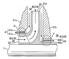
- FIG. 2 is an enlarged cross-sectional view of the first stage impeller 21a of the high-pressure pump 1 shown in FIG.
- the first stage impeller 21a includes a suction port 23 for sucking fluid and a discharge port 25 for discharging fluid.
- the pressure of the fluid is low on the suction port 23 side and high on the discharge port 25 side. That is, the suction port 23 is a low pressure part 36, and the discharge port 25 is a high pressure part 38.
- the fluid leaking portion in the high-pressure pump 1 is mainly a facing portion X between the outer peripheral surface of the suction port 23 and the casing 31a, and a facing portion Y between the outer peripheral surface of the rear surface of the impeller 21a and the casing 31b.
- Non-contact annular seals 41 and 43 according to the present embodiment are provided in the gaps formed in the facing portions X and Y, respectively.
- the non-contact annular seals 41 and 43 include rotating bodies 41a and 43a provided on the impeller 21a that is a rotating part of the high-pressure pump 1, and fixed bodies 41b and 43b provided on the casings 31a and 31b that are fixed parts.
- the rotating bodies 41a and 43a are provided as members different from the impeller 21a, but the rotating bodies 41a and 43a may be formed integrally with the impeller 21a.
- the fixed bodies 41b and 43b are provided as members different from the casings 31a and 31b in the illustrated example, the fixed bodies 41b and 43b may be formed integrally with the casings 31a and 31b.
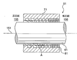
- FIG. 3 is a partial cross-sectional view showing the non-contact annular seal of this embodiment applicable to the non-contact annular seals 41 and 43 shown in FIG.
- the fixed body 71 is shown in a sectional view
- the rotating body 61 is shown in a side view.
- the non-contact annular seal 51 of the present embodiment is provided on the rotating body 61 provided on the impeller 21a which is the rotating part shown in FIG. 2 and the casings 31a and 31b which are the fixing parts shown in FIG. And a fixed body 71 provided.
- the rotating body 61 is configured to be rotatable together with the impeller 21a.
- the rotating body 61 rotates in a predetermined direction around the central axis 151.
- the center axis 151 coincides with the axis of the main shaft 11 shown in FIGS. 1 and 2, for example.
- the fixed body 71 includes a screw groove 81 formed in a spiral shape on the inner surface thereof. That is, the non-contact annular seal 51 of this embodiment is a thread groove seal.
- the fixed body 71 is formed in a substantially cylindrical shape.
- the rotating body 61 is a substantially cylindrical member having an outer diameter smaller than the inner diameter of the fixed body 71.
- the rotating body 61 is disposed inside the fixed body 71 so as to have a predetermined gap with respect to the inner surface of the fixed body 71.
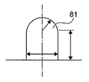
- the cross-sectional shape of the thread groove 81 formed in the fixed body 71 is substantially rectangular.
- the present invention is not limited to this, and the cross-sectional shape of the thread groove 81 may be substantially triangular as shown in FIG. 4A.
- the cross-sectional shape of the thread groove 81 may be a substantially U shape.
- the cross-sectional shape of the thread groove 81 may be a substantially semicircular shape.
- any cross-sectional shape other than the cross-sectional shapes shown in FIGS. 3 and 4A-4C can be adopted.
- the lead angle of the screw groove 81 on the high pressure side 155 is the same as that of the screw groove 81 on the low pressure side 156 (seal outlet side).
- a screw groove 81 is formed so as to be larger than the lead angle. That is, in the non-contact annular seal 51 according to the present embodiment, unstable vibration is efficiently suppressed by the screw groove 81 on the high pressure side, and the amount of leakage is reduced by the screw groove 81 on the low pressure side. Therefore, the non-contact annular seal 51 according to the present embodiment can achieve both the effect of suppressing unstable vibration and high shaft seal performance.
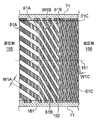
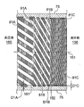
- FIG. 5 is a cross-sectional view of the fixed body 71 shown in FIG. 3 cut along a plane including the central axis 151.
- the fixed body 71 includes a screw groove 81A located on the high pressure side 155 (seal inlet side), a screw groove 81C located on the low pressure side 156 (seal outlet side), and a screw groove 81A and a screw groove 81C. And a screw groove 81B positioned therebetween.
- the screw groove 81 is referred to as a general term for the entire screw grooves 81A, 81B, and 81C.
- the thread grooves 81A, 81B, and 81C define lead angles ⁇ 1A, ⁇ 1B, and ⁇ 1C with respect to a plane orthogonal to the axial direction of the rotating body 61 (see FIG. 3) (the axial direction of the central axis 151), respectively.
- the screw grooves 81A, 81B, 81C have widths W1A, W1B, W1C, respectively.
- the widths W1A, W1B, and W1C indicate the shortest distances in the width direction from arbitrary points on the side surfaces of the thread grooves 81A, 81B, and 81C.
- the depths of the thread grooves 81A, 81B, 81C are all the same.
- the screw groove 81 has boundary portions 161 and 162 where the lead angle of the screw groove 81 changes. Specifically, the lead angle ⁇ 1A of the screw groove 81A changes to the lead angle ⁇ 1B of the screw groove 81B at the boundary portion 161. Further, the lead angle ⁇ 1B of the screw groove 81B changes to the lead angle ⁇ 1C of the screw groove 81C at the boundary portion 162. Since the boundary portions 161 and 162 do not have a substantial width, the thread groove 81 is continuously formed on the surface of the fixed body 71. In the present embodiment, the boundary portions 161 and 162 are formed in parallel with a plane orthogonal to the central axis 151.
- boundary portions 161 and 162 are not limited to being formed in a planar shape or a straight shape, and may have any shape. Further, as will be described later, the number of the boundary portions 161 and 162 is not limited to two, and may be one or three or more (see FIGS. 10 and 11).
- the lead angle ⁇ 1A is larger than the lead angle ⁇ 1B. Further, the lead angle ⁇ 1B is larger than the lead angle ⁇ 1C. Accordingly, the lead angle of the thread groove 81 is formed so as to decrease stepwise from the high pressure side 155 toward the low pressure side 156. That is, since the lead angle ⁇ 1A of the thread groove 81A is relatively large on the high-pressure side 155 that has a large effect of suppressing the destabilizing vibration, the effect of suppressing the destabilizing vibration can be improved.
- the lead angle ⁇ 1B of the screw groove 81B and the lead angle ⁇ 1C of the screw groove 81C are relatively small, so that an increase in the amount of fluid leaking through the non-contact annular seal 51 is suppressed. Can do.
- the thread groove 81 is formed so that its lead angle gradually decreases from the high pressure side 155 toward the low pressure side 156, the thread groove 81 can be easily processed in the fixed body 71.
- the thread groove 81 can be formed by processing thread grooves 81A, 81B, 81C having a certain width on the inner peripheral surface of the fixed body 71, respectively.
- a fixed body having a screw groove 81A, a fixed body having a screw groove 81B, and a fixed body having a screw groove 81C are manufactured, and the fixed body 71 is easily manufactured by combining these fixed bodies. Can do.
- the number of thread grooves 81A, the number of thread grooves 81B, and the number of thread grooves 81C are the same.
- the width of the thread groove 81 decreases as the lead angle decreases.
- the width W1A of the screw groove 81A on the high pressure side 155 from the boundary portion 161 is larger than the width W1B of the screw groove 81B on the low pressure side 156 from the boundary portion 161.
- the width W1B of the screw groove 81B on the high pressure side 155 from the boundary portion 162 is larger than the width W1C of the screw groove 81C on the low pressure side 156 from the boundary portion 162.
- the width of the thread groove 81 is formed so as to decrease stepwise from the high pressure side 155 toward the low pressure side 156.
- the number of threads 81A, the number of threads 81B, and the number of threads 81C may be different (see FIG. 7).
- the width W1A, the width W1B, and the width W1C may be the same size (see FIG. 7).
- the cross-sectional area of the thread groove 81A on the high-pressure side 155 is the same as the cross-sectional area of the thread groove 81B on the low-pressure side 156 at the boundary 161.
- the cross-sectional area of the screw groove 81B on the high-pressure side 155 is the same as the cross-sectional area of the screw groove 81C on the low-pressure side 156.
- the cross-sectional area of the screw groove 81 on the high-pressure side 155 in the boundary portions 161 and 162 may be different from the cross-sectional area of the screw groove 81 on the low-pressure side 156 (see FIG. 7).
- the screw groove 81 on the high pressure side 155 is formed continuously with the screw groove 81 on the low pressure side 156 at the boundary portions 161 and 162.
- the cross section of the thread groove 81 on the high pressure side 155 coincides with the cross section of the thread groove 81 on the low pressure side 156 at the boundary portions 161 and 162.
- the cross section of the screw groove 81A on the high pressure side 155 coincides with the cross section of the screw groove 81B on the low pressure side 156.
- the cross section of the thread groove 81B on the high pressure side 155 coincides with the cross section of the thread groove 81C on the low pressure side 156.
- the screw groove 81 on the high pressure side 155 may be formed so as not to be continuous with the screw groove 81 on the low pressure side 156 (see FIGS. 6 and 7).
- the non-contact annular seal 51 shown in FIG. 3 has the fixed body 71 in which the lead angle of the screw groove 81 on the high pressure side 155 is larger than the lead angle of the screw groove 81 on the low pressure side 156.
- This non-contact annular seal 51 can also be provided with other fixed bodies as described below, for example.
- FIG. 6 is a cross-sectional view showing another example of a fixed body used in the non-contact annular seal 51 shown in FIG. 6 shows a cross-sectional view of the fixed body when cut along a plane including the central axis 151 shown in FIG.
- the fixed body 72 shown in FIG. 6 differs from the fixed body 71 shown in FIG. 5 in that the thread groove 81 is discontinuous at the boundary portions 161 and 162.
- the other parts of the fixed body 72 are the same as the fixed body 71 shown in FIG.
- the cross section of the screw groove 81 on the high pressure side 155 is formed so as not to coincide with the cross section of the screw groove 81 on the low pressure side 156 at the boundary portions 161 and 162. Specifically, in the boundary portion 161, the cross section of the thread groove 81A on the high pressure side 155 does not coincide with the cross section of the thread groove 81B on the low pressure side 156. Further, at the boundary 162, the cross section of the screw groove 81B on the high pressure side 155 does not coincide with the cross section of the screw groove 81C on the low pressure side 156.
- FIG. 7 is a cross-sectional view showing still another example of a fixed body used in the non-contact annular seal 51 shown in FIG.
- FIG. 7 shows a cross-sectional view of the fixed body when cut along a plane including the central axis 151 shown in FIG.
- the fixing body 73 shown in FIG. 7 differs from the fixing body 71 shown in FIG. 5 in that the cross-sectional area of the screw groove 81 on the high-pressure side 155 is different from that on the low-pressure side 156. Are different from each other in that the width of the screw groove 81 is constant.
- the other parts of the fixed body 73 are the same as the fixed body 71 shown in FIG.
- the cross-sectional area of the thread groove 81A on the high-pressure side 155 is different from the cross-sectional area of the thread groove 81B on the low-pressure side 156. Further, in the boundary portion 162, the cross-sectional area of the screw groove 81B on the high-pressure side 155 is different from the cross-sectional area of the screw groove 81C on the low-pressure side 156. Since the screw groove 81 is formed such that the cross-sectional area of the screw groove 81 changes at the boundary portions 161 and 162, the number of threads of the screw groove 81 can be changed before and after the boundary portions 161 and 162. For this reason, the lead angles ⁇ 1A, ⁇ 1B, and ⁇ 1C of the thread grooves 81A, 81B, and 81C can be set more flexibly.
- the cross section of the screw groove 81 on the high pressure side 155 is formed so as not to coincide with the cross section of the screw groove 81 on the low pressure side 156.
- the cross section of the thread groove 81A on the high pressure side 155 does not coincide with the cross section of the thread groove 81B on the low pressure side 156.
- the cross section of the screw groove 81B on the high pressure side 155 does not coincide with the cross section of the screw groove 81C on the low pressure side 156.
- the width W1A of the screw groove 81A on the high-pressure side 155 from the boundary portion 161 is the same as the width W1B of the screw groove 81B on the low-pressure side 156 from the boundary portion 161.
- the width W1B of the screw groove 81B on the high pressure side 155 from the boundary portion 162 is the same as the width W1C of the screw groove 81C on the low pressure side 156 from the boundary portion 162.
- the number of threads 81A, the number of threads 81B, and the number of threads 81C are different. Specifically, the number of threads of the screw groove 81A is larger than the number of threads of the screw groove 81B, and the number of threads of the screw groove 81B is larger than the number of threads of the screw groove 81C.
- FIG. 8 is a cross-sectional view showing still another example of a fixed body used in the non-contact annular seal 51 shown in FIG.
- FIG. 8 shows a cross-sectional view of the fixed body when cut along a plane including the central axis 151 shown in FIG.
- the fixed body 74 shown in FIG. 8 is different from the fixed body 71 shown in FIG. 5 in that the boundary portions 161 and 162 have a predetermined width.
- the other parts of the fixed body 74 are the same as the fixed body 71 shown in FIG.
- the boundary 161 between the screw groove 81A and the screw groove 81B has a predetermined width. Further, the boundary portion 162 between the screw groove 81B and the screw groove 81C has a predetermined width.
- the thread groove 81 is intermittently formed on the surface of the fixed body 74. Thus, even if the thread groove 81 is intermittently formed on the surface of the fixed body 74, the same operation as that of the fixed body 71 shown in FIG.
- FIG. 9 is a cross-sectional view showing still another example of a fixed body used in the non-contact annular seal 51 shown in FIG. 9 shows a cross-sectional view of the fixed body when cut along a plane including the central axis 151 shown in FIG.
- the fixing body 75 shown in FIG. 9 is different from the fixing body 71 shown in FIG. 5 in that the depth of the screw groove 81 is gradually reduced.
- the other parts of the fixed body 75 are the same as the fixed body 71 shown in FIG.
- the thread grooves 81A, 81B, 81C have depths D1A, D1B, D1C, respectively.
- the depth D1A of the screw groove 81A on the high pressure side 155 from the boundary portion 161 is larger than the depth D1B of the screw groove 81B on the low pressure side 156 from the boundary portion 161.
- the depth D1B of the screw groove 81B on the high-pressure side 155 from the boundary portion 162 is larger than the depth D1C of the screw groove 81C on the low-pressure side 156 from the boundary portion 162.
- a non-contact annular seal when the lead angle of a thread groove having a predetermined number of threads is increased, the width of the thread groove has to be increased, and the sum of the sectional areas of the thread grooves is increased. Further, when the lead angle of the thread groove having a predetermined width is increased, the number of strips is inevitably increased, and the sum of the cross-sectional areas of the thread grooves is increased. When the total sum of the cross-sectional areas of the thread grooves increases, the fluid easily flows between the seals.
- the width of the screw groove 81A is relatively large, The sum total of the cross-sectional areas of the screw grooves 81 is increased. Therefore, as in the fixed body 75 shown in FIG. 9, the depth of the thread groove 81 is gradually decreased from the high pressure side 155 toward the low pressure side 156, thereby reducing the cross-sectional area of the thread groove 81. The sum can be reduced. Thereby, the leakage amount of the fluid passing between the seals can be further reduced.
- FIG. 10 is a cross-sectional view showing still another example of a fixed body used in the non-contact annular seal 51 shown in FIG. 10 shows a cross-sectional view of the fixed body when cut along a plane including the central axis 151 shown in FIG.
- the fixed body 76 shown in FIG. 10 is different from the fixed body 71 shown in FIG. 5 in that there are many lead angle change positions (boundary portions).
- the other parts of the fixed body 76 are the same as the fixed body 71 shown in FIG.
- the fixed body 76 has a boundary portion 163 on the high-pressure side 155 in addition to the boundary portions 161 and 162. Accordingly, the fixed body 76 has a thread groove 81D on the high-pressure side in addition to the thread grooves 81A, 81B, 81C.
- the lead angle ⁇ 1D of the screw groove 81D is larger than the lead angle ⁇ 1A of the screw groove 81A.
- the lead angles of the thread groove 81 change at more positions than the fixed body 71 shown in FIG. 5 due to the boundary portions 161, 162, and 163. Therefore, the lead angle of the thread groove 81 can be finely set to an appropriate angle according to the axial position. As a result, the effect of suppressing unstable vibration of the non-contact annular seal 51 and the shaft seal performance can be further improved.
- the number of boundary portions 161, 162, and 163 is not limited to three, and may be four or more.
- FIG. 11 is a cross-sectional view showing still another example of a fixed body used for the non-contact annular seal 51 shown in FIG. 11 shows a cross-sectional view of the fixed body when cut along a plane including the central axis 151 shown in FIG.
- the fixed body 77 shown in FIG. 11 is different from the fixed body 71 shown in FIG. 5 in that the change position (boundary portion) of the lead angle is small.
- the other parts of the fixed body 77 are the same as the fixed body 71 shown in FIG.
- the fixed body 77 has only the boundary portion 161. Therefore, the fixed body 77 does not have the screw groove 81C shown in FIG. 5, but has only the screw groove 81A and the screw groove 81B. Thus, if the fixed body 71 has at least one boundary portion 161 and has at least two screw grooves 81A and screw grooves 81B, the same operation as the fixed body 71 shown in FIG. 5 is achieved. obtain.
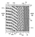
- FIG. 12 is a cross-sectional view showing still another example of a fixed body used in the non-contact annular seal 51 shown in FIG. 12 shows a cross-sectional view of the fixed body when cut along a plane including the central axis 151 shown in FIG.
- the fixing body 78 shown in FIG. 12 is different from the fixing body 71 shown in FIG. 5 in that the lead angle ⁇ 1 of the screw groove 81 is continuously reduced.
- the fixing body 78 is formed with a thread groove 81 so that the lead angle ⁇ 1 continuously decreases from the high pressure side 155 toward the low pressure side 156. Therefore, the fixed body 78 does not have a boundary portion where the lead angle ⁇ 1 changes like the boundary portions 161 and 162 shown in FIG.
- the number of threads of the thread groove 81 does not change between the high pressure side 155 and the low pressure side 156, and the width of the thread groove 81 is from the high pressure side 155 toward the low pressure side 156.
- a screw groove 81 is formed so as to be continuously reduced.
- the lead angle ⁇ ⁇ b> 1 of the screw groove 81 changes at more positions than the fixed body 71 shown in FIG. 5. Therefore, the lead angle ⁇ 1 of the screw groove 81 can be finely set to an appropriate angle according to the axial position. As a result, the effect of suppressing unstable vibration of the non-contact annular seal 51 and the shaft seal performance can be further improved. It is also possible to incorporate a portion where the lead angle continuously changes like the screw groove 81 shown in FIG. 12 into the fixed body shown in FIGS.
- the screw groove 81 described above is described as being provided on the fixed body, but is not limited thereto, and may be provided on the outer peripheral surface of the rotating body 62 shown in FIG. However, the screw groove 81 is preferably formed at least on the surface of the fixed body. By forming the screw groove 81 at least on the surface of the fixed body, it is possible to suppress an increase in leakage while improving the effect of suppressing unstable vibration.
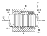
- FIG. 13 is a partial cross-sectional view showing a non-contact annular seal of another embodiment applicable to the non-contact annular seals 41 and 43 shown in FIG.
- the non-contact annular seal 52 shown in FIG. 13 is different from the non-contact annular seal 51 shown in FIG.
- the other parts of the non-contact annular seal 52 are the same as the non-contact annular seal 51 shown in FIG.
- the non-contact annular seal 52 shown in FIG. 13 has one of the fixed bodies 72, 73, 74, 75, 76, 77, and 78 shown in FIGS. Also good.
- the non-contact annular seal 52 has a rotating body 62 having screw grooves 91A, 91B, 91C formed on the surface thereof.
- the screw grooves 91A, 91B, and 91C are collectively referred to as a screw groove 91.
- the thread grooves 91A, 91B, 91C have the same shape as the thread grooves 81A, 81B, 81C formed in the fixed body 71. That is, the thread groove 91 has boundary portions 164 and 165 where the lead angle of the thread groove 91 changes, and the lead angle of the thread groove 91 is gradually reduced from the high pressure side 155 toward the low pressure side 156. It is formed.
- the screw groove 91 When the screw groove 91 is provided in the rotating body 62 of the non-contact annular seal 52, the pumping effect of pushing back the fluid to the high pressure side 155 by the rotation of the rotating body 62 increases. On the other hand, the rotation of the rotator 62 may cause the fluid around the rotator 62 to swirl and promote unstable vibration. However, since the screw groove 81 is formed on the surface of the fixed body 71, even if the screw groove 91 is formed on the surface of the rotating body 62, the swirling of the fluid generated by the rotation of the rotating body 62 is performed. The screw groove 91 can be suppressed. In this case, the amount of fluid leakage can be further reduced by the pumping effect of the thread groove 91 formed on the surface of the rotating body 62.
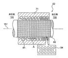
- the non-contact annular seal 52 may have a parallel groove 92 on the surface of the rotating body 62 as shown in FIG. Further, the non-contact annular seal 52 may have a damper seal 93 adopting a honeycomb pattern on the surface of the rotating body 62 as shown in FIG. 15, and on the surface of the rotating body 62 as shown in FIG. You may have the damper seal
- the minimum inner diameter of the fixed body 71 means the inner diameter of the fixed body 71 at the screw thread position.
- Axial length of fixed body 71 / minimum inner diameter of fixed body 71 0.817 Clearance between inner peripheral surface of fixed body 71 and outer peripheral surface of rotating body 61 / minimum inner diameter of fixed body 71: 0.004 Number of screw threads: 8 Pump rotation speed: 3000rpm Differential pressure between seal inlet side and seal outlet side: 1.0 MPa
- the axial lengths of the thread groove 81A, the thread groove 81B, and the thread groove 81C are the same. That is, the thread groove 81A is formed in the 1/3 region on the high pressure side 155 of the inner peripheral surface of the fixed body 71, the screw groove 81C is formed in the 1/3 region on the low pressure side 156, and the screw groove 81C is formed in the remaining 1/3 intermediate region. A groove 81B is formed.
- Comparative Example 1 is a pump using a non-contact annular seal in which the lead angle of the thread groove 81 is the lead angle ⁇ 1B.
- Comparative Example 2 is a pump using a non-contact annular seal in which the lead angle of the thread groove 81 is the lead angle ⁇ 1A.
- Comparative Example 3 is a pump using a non-contact annular seal in which the lead angle of the thread groove 81 is the lead angle ⁇ 1C.
- FIG. 17 is a graph showing the results of this evaluation test.
- the destabilizing force and leakage amount of Comparative Example 2, Comparative Example 3, and Example are shown with the destabilizing force and leakage amount of Comparative Example 1 being 100%.
- the destabilizing force is suppressed to 31%, and the unstable vibration is reduced compared to the comparative example 1.
- the amount has increased to 128%.
- Comparative Example 3 having a relatively small lead angle ⁇ 1C the leakage amount is reduced to 92%, and the leakage amount is suppressed as compared with Comparative Example 1, but the destabilizing force is 200%. It can be seen that it has increased.
- the destabilizing force is 42% and the leakage amount is 100%.
- the increase in the amount of fluid leaking through the seal can be suppressed while the unstable vibration is effectively suppressed.
Landscapes
- Engineering & Computer Science (AREA)
- General Engineering & Computer Science (AREA)
- Mechanical Engineering (AREA)
- Structures Of Non-Positive Displacement Pumps (AREA)
- Sealing Using Fluids, Sealing Without Contact, And Removal Of Oil (AREA)
Abstract
回転軸の周方向の旋回流に起因する不安定振動の抑制効果の向上を図りつつ、シール内部を通過する流体の漏れ量の増加を抑制する。 本発明によれば、回転機械の回転部に設けられる回転体と、前記回転機械の固定部に設けられる固定体と、を有し、前記回転体と前記固定体との隙間を流れる流体をシールするように構成された非接触環状シールが提供される。非接触環状シールは、前記隙間を形成する前記回転体の表面及び前記固定体の表面の少なくとも一方に設けられるネジ溝を有し、前記ネジ溝は、前記回転体の軸方向に直交する平面に対する前記ネジ溝のリード角を画定し、シール入口側の前記ネジ溝の前記リード角は、シール出口側の前記ネジ溝の前記リード角よりも大きい。
Description
本発明は、非接触環状シール及びこれを備える回転機械に関し、特に、非圧縮性流体を扱う回転機械における、羽根車等とケーシングとの間の流体の漏洩量を低減し且つ振動を少なくし、安定した軸封特性を発揮する非接触環状シール及びこれを備える回転機械に関する。
液体を移送する回転機械(以下、「ポンプ」という)は、発電、化学プロセス、下水道、上水道等を目的とするプラント又は設備に幅広く使用されている。ポンプは、ケーシングと、羽根車を装着した回転軸とを有する。回転軸は、ケーシング内部に配置され、軸受により回転可能に支持される。ケーシングの吸込口から吸い込まれた液体は、羽根車の回転により昇圧され、ケーシングの吐出口から吐出される。即ち、ポンプ内部の流路においては、高圧の領域と低圧の領域とが形成され、高圧領域から低圧領域へと流体が流れる。ここで、ケーシング(固定部)と回転軸(回転部)との僅かな隙間において、高圧の領域からこの隙間を介して低圧の領域へと流体が移動(漏洩)すると、ポンプ効率が低下する。このため、ケーシングと回転軸との隙間は非接触環状シールによりシールされる。これにより、昇圧された液体が低圧側へ漏洩することが抑制される。
例えば、図1に示す典型的な多段遠心ポンプ(JISハンドブック ポンプ 第1版 第74頁から引用)では、非接触環状シールは、図中丸で囲まれた部位に用いられる。即ち、羽根車の入口部、前段の羽根車と後段の羽根車との間、最後段の羽根車出口部と低圧側(ポンプ入口圧力)との間等に用いられる。特に、羽根車出口部と低圧側との間は差圧が大きく、流体の漏洩が大きいので、この部分における流体の漏洩はポンプ性能に与える影響が大きい。このため、流体の漏洩量を減らすことができる様々な構造の非接触環状シールが知られている。
最も基本的な非接触環状シールとしては、平滑シールが知られている。平滑シールは、平滑な面を有する円筒を二重に配置して形成されたシールである。平滑シールのような非接触環状シールの漏れ量を低減するためには、非接触環状シールの回転側と静止側の径方向の隙間を小さくすることが効果的である。しかしながら、回転軸の振動やたわみ等の実用上の問題から、径方向の隙間を極端に小さくすることはできない。このため、径方向の隙間を小さくすることなく漏れ量を低減する非接触環状シールが必要とされる。このような非接触環状シールとして、平行溝シール、ダンパーシール、ネジ溝シール等が知られている。以下、従来の非接触環状シールの例を説明する。
図18は、従来の平行溝シールの部分断面図である。図18においては、固定体131を断面図で示し、回転軸121を側面図で示している。平行溝シール111は、外周面が平滑な回転体である回転軸121と、回転軸121と対向する面に同心円状の溝141が複数設けられた固定体131とを有する。この平行溝シール111は、回転軸121と固定体131との隙間を流れる流体が溝141を通過する際に発生する渦によるエネルギー損失や、流路の急拡大及び急縮小により発生する圧力損失等により、流体の漏洩量(移動量)を低減することができる。
図19及び図20は、従来のダンパーシールの部分断面図である。図19はダンパー構造としてハニカムパターンを採用したダンパーシールを示す。図19においては、固定体132を断面図で示し、回転軸122を側面図で示している。ダンパーシール112は、外周面が平滑な回転体である回転軸122と、回転軸122と対向する面に複数の凹部142が設けられた固定体132とを有する。図示の例では、凹部142として六角形状のハニカムパターンが用いられている。このダンパーシール112は、回転軸122と固定体132との隙間を流れる流体が凹部142を流れる際に発生する流体の圧力損失により、流体の漏洩量を低減することができる。
図20はダンパー構造としてホールパターンを採用したダンパーシールを示す。図20においては、固定体133を断面図で示し、回転軸123を側面図で示している。このダンパーシール113は、外周面が平滑な回転体である回転軸123と、回転軸123と対向する面に複数の凹部143が設けられた固定体133とを有する。図示の例では、凹部143として円形凹状のホールパターンが用いられている。このダンパーシール113は、回転軸123と固定体133との隙間を流れる流体が凹部143を流れる際に発生する流体の圧力損失により、流体の漏洩量を低減することができる。
図21は、従来のネジ溝シールの部分断面図である。図21においては、固定体134を断面図で示し、回転軸124を側面図で示している。ネジ溝シール114は、内周面が平滑な円筒状の固定体134と、固定体134と対向する面にネジ溝144が形成された回転軸124とを有する。ネジ溝シール114は、回転軸124が回転すると、回転方向に応じてポンピング効果により流体を高圧側に押し戻し、漏洩量を低減させる効果がある。ネジ溝144はシール入口側(高圧側)からシール出口側(低圧側)までの連続した溝である。ネジ溝シール114の入口側と出口側との圧力差が大きい場合は圧力差による漏れ流れが大きくなるので、リード角を小さくした方が漏れ量を小さくできる場合が多い。
なお、ターボ分子ポンプ等の流体機械に用いられる非接触環状シールが、実開昭62-98798号公報(特許文献1)等に開示されている。
ところで、非接触環状シールでは、シール内部を通過する流体が回転軸の外周を旋回することにより、回転軸に不安定振動(自励振動とも呼ばれる)が発生し、回転軸に異常な振動状態が生じる場合がある。この不安定振動の発生のし難さが非接触環状シールの重要な特性の一つとなっている。この不安定振動は、シール内部の回転軸の周方向の旋回流が大きいほど発生し易くなることがわかっている。
ネジ溝シールの場合、固定体に適切な溝を設けることで、回転軸の回転に伴うシール内部の流体の旋回流を低減させることができる。このため、固定体にネジ溝を有するネジ溝シールは、不安定振動を抑制する手段としてしばしば用いられる。この固定体に設けられるネジ溝による不安定振動を抑制する作用はネジ溝のリード角が大きいほど顕著であることが分かった。しかしながら、上述したように、ネジ溝のリード角を大きくすると漏れ量が大きくなることが多く、不安定振動を抑制する作用と漏れ量を低減する作用はトレードオフの関係にあるということができる。したがって、漏れ量を低減することと不安定振動を抑制することとを高いレベルで両立させることは困難であった。
本発明は、上記従来の問題点に鑑みてなされたものであり、その目的の一つは、回転軸の周方向の旋回流に起因する不安定振動の抑制効果の向上を図りつつ、シール内部を通過する流体の漏れ量の増加を抑制することである。
また、本発明の他の目的の一つは、羽根車を取付けた回転軸を回転させ、流体を移送する回転機械において、羽根車によって昇圧された流体が低圧側に漏れることを低減してポンプ効率を上げつつ、シール内部を通過する流体による不安定振動を抑制することである。
本発明者らは、上記問題点に対して鋭意検討した結果、以下の知見を得た。即ち、ネジ溝のリード角が比較的大きいネジ溝シールにおいては、低圧側(シール出口側)における不安定振動を抑制する作用よりも、高圧側(シール入口側)における不安定振動を抑制する作用が大きいことが分かった。また、ネジ溝のリード角が比較的小さいネジ溝シールは、その低圧側と高圧側とで、ほぼ同等の漏れ量を低減する効果を有することが分かった。
本発明は、上記知見に基づきなされた。本発明の一形態によれば、回転機械の回転部に設けられる回転体と、前記回転機械の固定部に設けられる固定体と、を有し、前記回転体と前記固定体との隙間を流れる流体をシールするように構成された非接触環状シールが提供される。この非接触環状シールは、前記隙間を形成する前記回転体の表面及び前記固定体の表面の少なくとも一方に設けられるネジ溝を有し、前記ネジ溝は、前記回転体の軸方向に直交する平面に対する前記ネジ溝のリード角を画定し、シール入口側の前記ネジ溝の前記リード角は、シール出口側の前記ネジ溝の前記リード角よりも大きい。これによれば、不安定化振動を抑制する作用が大きい高圧側(シール入口側)においては、ネジ溝のリード角が相対的に大きくされるので、不安定化振動を抑制する作用を向上させることができる。また、低圧側(シール出口側)においては、ネジ溝のリード角が相対的に小さくされるので、シールを通過する流体の漏れ量の増加を抑制することができる。したがって、本発明の一形態によれば、非接触環状シールの不安定振動を抑制する効果と高い軸封性能とを両立することができる。
本発明の他の一形態によれば、上記非接触環状シールの一形態において、前記ネジ溝は、前記ネジ溝のリード角がシール入口側からシール出口側に向かって段階的に小さくなるように形成される。これによれば、上記非接触環状シールは、リード角の異なるネジ溝を有する複数の非接触環状シールを互いに接合することで製造され得る。このため、上記非接触環状シールは、例えば、従来から存在する非接触環状シールを利用する等して、容易に製造することができる。
本発明の他の一形態によれば、上記非接触環状シールの一形態において、前記ネジ溝は、前記ネジ溝のリード角がシール入口側からシール出口側に向かって連続的に小さくなるように形成される。これによれば、ネジ溝のリード角を、軸方向位置に応じて適切な角度に細かく設定することができる。ひいては、非接触環状シールの不安定振動を抑制する効果と軸封性能とより向上させることができる。
本発明の他の一形態によれば、上記非接触環状シールの一形態において、シール入口側の前記ネジ溝の深さは、シール出口側の前記ネジ溝の深さよりも大きい。非接触環状シールにおいて所定の条数を有するネジ溝のリード角を大きくした場合、ネジ溝の幅を大きくせざるを得ず、ネジ溝の断面積の総和が大きくなる。また、所定の幅を有するネジ溝のリード角を大きくした場合は、条数を増加せざるを得ず、ネジ溝の断面積の総和が大きくなる。ネジ溝の断面積の総和が大きくなると、流体がシール間を流れやすくなる。本発明の一形態によれば、非接触環状シールのネジ溝の断面積の総和を小さくすることができるので、シール間を通過する流体の漏れ量をさらに低減することができる。
本発明の他の一形態によれば、上記非接触環状シールの一形態において、前記ネジ溝は、少なくとも前記固定体の前記表面に形成される。ネジ溝が少なくとも固定体の表面に形成されることにより、不安定振動を抑制する作用を向上させつつ、漏れ量の増加を抑制することができる。ところで、非接触環状シールの回転体にもネジ溝を設けた場合、回転体の回転により流体を高圧側に押し戻すポンピング効果が増加する。一方で、回転体の回転により、回転体の周囲の流体が旋回し、不安定振動が助長される可能性がある。ここで、固定体の表面に上記ネジ溝が形成されていれば、回転体の表面にネジ溝が形成されていても、回転体の回転により生じる流体の旋回を固定体の表面のネジ溝により抑制することができる。また、この場合、回転体の表面に形成されたネジ溝によるポンピング効果により、一層流体の漏れ量を低減することができる。したがって、固定体と回転体の両方に上記ネジ溝が形成されている場合は、不安定振動を抑制しつつ、漏れ量を一層抑制することができる。
本発明の他の一形態によれば、回転機械が提供される。この回転機械は、電動機と、前記電動機と連結されて回転可能に構成される主軸と、前記主軸に嵌合され、該主軸とともに回転可能に構成される羽根車と、前記羽根車を収容するケーシングと、前記ケーシングに取り付けられ、前記主軸を回転可能に支持する軸受と、を備え、前記主軸は回転部を有し、前記ケーシングは固定部を有し、前記回転部及び前記固定部は、上記非接触環状シールを有する。
本発明の一つによれば、回転軸の周方向の旋回流に起因する不安定振動の抑制効果の向上を図りつつ、シール内部を通過する流体の漏れ量の増加を抑制することができる。
また、本発明の一つによれば、羽根車を取付けた回転軸を回転させ、流体を移送する回転機械において、羽根車によって昇圧された流体が低圧側に漏れることを低減してポンプ効率を上げつつ、シール内部を通過する流体による不安定振動を抑制することができる。
以下、本発明の実施形態について図面を参照して説明する。以下で説明する図面において、同一の又は相当する構成要素には、同一の符号を付して重複した説明を省略する。なお、以下で説明する実施形態では、本発明の回転機械の一例として高圧ポンプが説明される。
図1は、本実施形態に係る非接触環状シールを適用することができる高圧ポンプ(多段遠心ポンプ)の断面図を示す。この高圧ポンプ1は、図示しない電動機に連結されて回転する主軸11と、主軸11に嵌合された羽根車21a,21b,21cと、羽根車21a,21b,21cを収容するケーシング31と、ケーシング31に取り付けられた軸受45a,45bとを備える。軸受45a,45bは、主軸11を回転可能に支持する。高圧ポンプ1を回転駆動するための図示しない電動機は、主軸11の左端に嵌合されたカップリング13を介して主軸11に連結される。
ケーシング31は水等の非圧縮性流体(以下、単に流体という)を外部から吸い込むための吸込口33と、吸い込んだ流体を吐出するための吐出口37を有する。主軸11に嵌合された1段目羽根車21aは、主軸11の回転に伴って回転し、吸込口33から流体をケーシング31内に吸い込む。1段目羽根車21aにより吸い込まれ、昇圧された流体は、第1流路35aを通過し、2段目羽根車21bへ到達する。2段目羽根車21bによって昇圧された流体は、第2流路35bを通過し、3段目羽根車21cへ到達する。流体は、3段目羽根車21cでさらに昇圧され、吐出口37より吐出され、図示しない配管を通じて移送される。即ち、流体は、1段目羽根車21a、2段目羽根車21b、及び3段目羽根車21cによって昇圧される。
流体には、各羽根車21a,21b,21cの吸込側と吐出側との間に圧力差が生じる。即ち、吸込側が低圧側になり、吐出側が高圧側になる。この圧力差が生じると、僅かな隙間を通じて、高圧側の流体の一部は低圧側へ漏洩する。本実施形態の非接触環状シールは、その漏洩を低減する。図1に示した高圧ポンプ1では、円で囲んだ部位に本実施形態の非接触環状シールが設けられる。図1に示した高圧ポンプ1は多段遠心ポンプであるので、流体の圧力が単段遠心ポンプに比べて高くなり、流体の漏洩量は必然的に多くなる。漏洩量が多ければ、ポンプ効率は低下する。
図2は、図1に示した高圧ポンプ1の1段目羽根車21aの拡大断面図である。図示のように、1段目羽根車21aは流体を吸い込む吸込口23と、流体を吐出する吐出口25とを有する。ここで、流体の圧力は、吸込口23側が低圧になり、吐出口25側が高圧となる。即ち、吸込口23は低圧部36であり、吐出口25は高圧部38である。ここで、高圧ポンプ1における流体の漏洩箇所は主に、吸込口23の外周面とケーシング31aとの対向部位Xと、羽根車21aの背面の外周面とケーシング31bとの対向部位Yである。これら各対向部位X,Yに形成される隙間に、本実施形態に係る非接触環状シール41,43が設けられる。
非接触環状シール41,43は、高圧ポンプ1の回転部である羽根車21aに設けられる回転体41a,43aと、固定部であるケーシング31a,31bに設けられる固定体41b,43bと、を有する。なお、図示の例では回転体41a,43aが羽根車21aとは別の部材として設けられているが、回転体41a,43aは羽根車21aと一体に形成されていてもよい。同様に、図示の例では固定体41b,43bがケーシング31a,31bとは別の部材として設けられているが、固定体41b,43bはケーシング31a,31bと一体に形成されていてもよい。
図3は、図2に示した非接触環状シール41,43に適用可能な本実施形態の非接触環状シールを示す部分断面図である。図3においては、固定体71を断面図で示し、回転体61を側面図で示している。
図示のように、本実施形態の非接触環状シール51は、図2に示した回転部である羽根車21aに設けられる回転体61と、図2に示した固定部であるケーシング31a,31bに設けられる固定体71とを備える。回転体61は、羽根車21aとともに回転可能に構成される。回転体61は、中心軸151を中心として所定の方向に回転する。なお、中心軸151は、例えば、図1及び図2に示した主軸11の軸心と一致する。
また、固定体71は、その内表面にらせん状に形成されたネジ溝81を備える。即ち、本実施形態の非接触環状シール51はネジ溝シールである。固定体71は略円筒状に形成される。回転体61は、固定体71の内径よりも小さい外径を有する略円筒状の部材である。回転体61は、固定体71の内面に対して所定の隙間を有するように、固定体71の内部に配置される。
非接触環状シール51が図1に示した高圧ポンプ1に適用されるとき、流体は、固定体71と回転体61との隙間を、高圧側155(シール入口側)から低圧側156(シール出口側)に向かって、即ち図中矢印Aの方向に向かって漏洩する。
図3に示すように、固定体71に形成されるネジ溝81の断面形状は略矩形である。しかしながら、これに限らず、図4Aに示すようにネジ溝81の断面形状は略三角形であってもよい。また、図4Bに示すように、ネジ溝81の断面形状は略U字形であってもよい。さらに、図4Cに示すように、ネジ溝81の断面形状は略半円形であってもよい。なお、ネジ溝81の断面形状としては、図3及び図4A-4Cに示した断面形状以外の任意の断面形状を採用することもできる。
上述したように、本発明者らは、鋭意検討により以下の知見を得た。即ち、ネジ溝のリード角が比較的大きいネジ溝シールにおいては、低圧側(シール出口側)における不安定振動を抑制する作用よりも、高圧側(シール入口側)における不安定振動を抑制する作用が大きいことが分かった。また、ネジ溝のリード角が比較的小さいネジ溝シールは、その低圧側と高圧側とで、ほぼ同等の漏れ量を低減する効果を有することが分かった。
このため、図3に示した本実施形態に係る非接触環状シール51では、高圧側155(シール入口側)のネジ溝81のリード角が、低圧側156(シール出口側)のネジ溝81のリード角よりも大きくなるように、ネジ溝81が形成される。即ち、本実施形態に係る非接触環状シール51では、高圧側におけるネジ溝81により不安定振動を効率よく抑制し、且つ低圧側におけるネジ溝81により漏れ量を低減する。したがって、本実施形態に係る非接触環状シール51は、不安定振動を抑制する効果と高い軸封性能とを両立することができる。
図5は、図3に示した固定体71の、中心軸151を含む平面で切断した場合の断面図である。図示のように固定体71は、高圧側155(シール入口側)に位置するネジ溝81Aと、低圧側156(シール出口側)に位置するネジ溝81Cと、ネジ溝81Aとネジ溝81Cとの間に位置するネジ溝81Bとを有する。ここでは、ネジ溝81A,81B,81Cの全体の総称としてネジ溝81と呼ぶ。ネジ溝81A,81B,81Cは、それぞれ、回転体61(図3参照)の軸方向(中心軸151の軸方向)に直交する平面に対するリード角θ1A,θ1B,θ1Cを画定する。また、ネジ溝81A,81B,81Cは、それぞれ、幅W1A,W1B,W1Cを有する。ここで、幅W1A,W1B,W1Cは、ネジ溝81A,81B,81Cの側面の任意の点からの幅方向の最短距離を示す。なお、ネジ溝81A,81B,81Cの深さは全て同一である。
ネジ溝81は、ネジ溝81のリード角が変化する境界部161,162を有する。具体的には、ネジ溝81Aのリード角θ1Aは、境界部161においてネジ溝81Bのリード角θ1Bに変化する。また、ネジ溝81Bのリード角θ1Bは、境界部162においてネジ溝81Cのリード角θ1Cに変化する。境界部161,162は実質的な幅を有していないので、ネジ溝81は、固定体71の表面に連続的に形成される。なお、本実施形態では、境界部161,162は、中心軸151に直交する平面と平行に形成される。しかしながら、この境界部161,162は、平面状又は直線状に形成される場合に限らず、任意の形状であってもよい。また、後述するように、境界部161,162の数は、2つに限らず、1又は3以上であってもよい(図10及び図11参照)。
ここで、リード角θ1Aは、リード角θ1Bよりも大きい。また、リード角θ1Bは、リード角θ1Cよりも大きい。したがって、ネジ溝81のリード角は、高圧側155から低圧側156に向かって段階的に小さくなるように形成される。即ち、不安定化振動を抑制する作用が大きい高圧側155においては、ネジ溝81Aのリード角θ1Aが相対的に大きくされるので、不安定化振動を抑制する作用を向上させることができる。また、低圧側156においては、ネジ溝81Bのリード角θ1B及びネジ溝81Cのリード角θ1Cが相対的に小さくされるので、非接触環状シール51を通過する流体の漏れ量の増加を抑制することができる。
また、ネジ溝81は、そのリード角が高圧側155から低圧側156に向かって段階的に小さくなるように形成されるので、この固定体71にネジ溝81を容易に加工することができる。具体的には、ネジ溝81は、固定体71の内周面に、一定幅のネジ溝81A,81B,81Cをそれぞれ加工することで形成することができる。又は、例えばネジ溝81Aを有する固定体と、ネジ溝81Bを有する固定体と、ネジ溝81Cを有する固定体とそれぞれ製造し、これらの固定体を組み合わせることで固定体71を容易に製造することができる。
ネジ溝81Aの条数と、ネジ溝81Bの条数と、ネジ溝81Cの条数は、それぞれ同一である。ネジ溝81は、条数が一定の場合、リード角が小さくなるに従って、ネジ溝81の幅が小さくなる。このため、境界部161よりも高圧側155のネジ溝81Aの幅W1Aは、境界部161よりも低圧側156のネジ溝81Bの幅W1Bよりも大きい。また、境界部162よりも高圧側155のネジ溝81Bの幅W1Bは、境界部162よりも低圧側156のネジ溝81Cの幅W1Cよりも大きい。即ち、ネジ溝81の幅は、高圧側155から低圧側156に向かって段階的に小さくなるように形成される。なお、後述するように、ネジ溝81Aの条数と、ネジ溝81Bの条数と、ネジ溝81Cの条数は、それぞれ異なっていてもよい(図7参照)。また、後述するように、幅W1Aと、幅W1Bと、幅W1Cとは、互いに同一の大きさであってもよい(図7参照)。
図示のように、境界部161において、高圧側155のネジ溝81Aの断面積は、低圧側156のネジ溝81Bの断面積と同一である。同様に、境界部162において、高圧側155のネジ溝81Bの断面積は、低圧側156のネジ溝81Cの断面積と同一である。なお、後述するように、境界部161,162における高圧側155のネジ溝81の断面積は、低圧側156のネジ溝81の断面積と異なっていてもよい(図7参照)。
また、図示のように、境界部161,162において、高圧側155のネジ溝81は、低圧側156のネジ溝81に連続して形成される。言い換えれば、境界部161,162において、高圧側155のネジ溝81の断面が、低圧側156のネジ溝81の断面と一致する。具体的には、境界部161において、高圧側155のネジ溝81Aの断面は、低圧側156のネジ溝81Bの断面と一致する。また、境界部162において、高圧側155のネジ溝81Bの断面は、低圧側156のネジ溝81Cの断面と一致する。これにより、ポンピング効果が境界部161,162におけるネジ溝81によって阻害されることを抑制することができる。なお、後述するように、境界部161,162において、高圧側155のネジ溝81は、低圧側156のネジ溝81に連続しないように形成されてもよい(図6、図7参照)。
以上で説明したように、図3に示した非接触環状シール51は、高圧側155のネジ溝81のリード角が低圧側156のネジ溝81のリード角よりも大きい固定体71を有する。この非接触環状シール51は、例えば以下で説明するような他の固定体を備えることもできる。
図6は、図3に示した非接触環状シール51に使用される固定体の他の例を示す断面図である。図6においては、図3に示した中心軸151を含む平面で切断した場合の固定体の断面図を示す。図6に示す固定体72は、図5に示した固定体71に比べて、境界部161,162においてネジ溝81が不連続である点が異なる。固定体72の他の部分については、図5に示した固定体71と同一であり、その効果も同一であるので、詳細な説明は省略する。
図示のように、境界部161,162において、高圧側155のネジ溝81の断面は、低圧側156のネジ溝81の断面と一致しないように形成される。具体的には、境界部161において、高圧側155のネジ溝81Aの断面は、低圧側156のネジ溝81Bの断面と一致しない。また、境界部162において、高圧側155のネジ溝81Bの断面は、低圧側156のネジ溝81Cの断面と一致しない。
図7は、図3に示した非接触環状シール51に使用される固定体のさらに他の例を示す断面図である。図7においては、図3に示した中心軸151を含む平面で切断した場合の固定体の断面図を示す。図7に示す固定体73は、図5に示した固定体71に比べて、高圧側155のネジ溝81の断面積が低圧側156に比べて異なる点、境界部161,162においてネジ溝81が不連続である点、及びネジ溝81の幅が一定である点が異なる。
固定体73の他の部分については、図5に示した固定体71と同一であり、その効果も同一であるので、詳細な説明は省略する。
固定体73の他の部分については、図5に示した固定体71と同一であり、その効果も同一であるので、詳細な説明は省略する。
図示のように、境界部161において、高圧側155のネジ溝81Aの断面積は、低圧側156のネジ溝81Bの断面積と異なる。また、境界部162において、高圧側155のネジ溝81Bの断面積は、低圧側156のネジ溝81Cの断面積と異なる。ネジ溝81の断面積が境界部161,162において変化するようにネジ溝81が形成されるので、境界部161,162の前後においてネジ溝81の条数を変化させることができる。このため、ネジ溝81A,81B,81Cのリード角θ1A,θ1B,θ1Cをより柔軟に設定することができる。
また、境界部161,162において、高圧側155のネジ溝81の断面は、低圧側156のネジ溝81の断面と一致しないように形成される。具体的には、境界部161において、高圧側155のネジ溝81Aの断面は、低圧側156のネジ溝81Bの断面と一致しない。また、境界部162において、高圧側155のネジ溝81Bの断面は、低圧側156のネジ溝81Cの断面と一致しない。
また、図示のように、固定体73においては、境界部161よりも高圧側155のネジ溝81Aの幅W1Aが、境界部161よりも低圧側156のネジ溝81Bの幅W1Bと同一である。また、境界部162よりも高圧側155のネジ溝81Bの幅W1Bが、境界部162よりも低圧側156のネジ溝81Cの幅W1Cと同一である。これにより、ネジ溝81Aの条数と、ネジ溝81Bの条数と、ネジ溝81Cの条数とが異なっている。具体的には、ネジ溝81Aの条数は、ネジ溝81Bの条数よりも多く、ネジ溝81Bの条数は、ネジ溝81Cの条数よりも多い。
図8は、図3に示した非接触環状シール51に使用される固定体のさらに他の例を示す断面図である。図8においては、図3に示した中心軸151を含む平面で切断した場合の固定体の断面図を示す。図8に示す固定体74は、図5に示した固定体71に比べて、境界部161,162が所定の幅を有する点が異なる。固定体74の他の部分については、図5に示した固定体71と同一であり、その効果も同一であるので、詳細な説明は省略する。
図8に示すように、ネジ溝81Aとネジ溝81Bとの間の境界部161が所定の幅を有する。また、ネジ溝81Bとネジ溝81Cとの間の境界部162が所定の幅を有する。言い換えれば、ネジ溝81は、固定体74の表面に間欠的に形成される。このように、ネジ溝81が固定体74の表面に間欠的に形成されても、図5に示した固定体71と同様の作用を奏し得る。
図9は、図3に示した非接触環状シール51に使用される固定体のさらに他の例を示す断面図である。図9においては、図3に示した中心軸151を含む平面で切断した場合の固定体の断面図を示す。図9に示す固定体75は、図5に示した固定体71に比べて、ネジ溝81の深さが段階的に浅くなるように形成されている点が異なる。固定体75の他の部分については、図5に示した固定体71と同一であり、その効果も同一であるので、詳細な説明は省略する。
図示のように、ネジ溝81A,81B,81Cは、それぞれ、深さD1A,D1B,D1Cを有する。境界部161より高圧側155のネジ溝81Aの深さD1Aは、境界部161より低圧側156のネジ溝81Bの深さD1Bよりも大きい。また、境界部162より高圧側155のネジ溝81Bの深さD1Bは、境界部162より低圧側156のネジ溝81Cの深さD1Cよりも大きい。
一般的に、非接触環状シールにおいて、所定の条数を有するネジ溝のリード角を大きくする場合、ネジ溝の幅を大きくせざるを得ず、ネジ溝の断面積の総和が大きくなる。また、所定の幅を有するネジ溝のリード角を大きくする場合は、条数を増加せざるを得ず、ネジ溝の断面積の総和が大きくなる。ネジ溝の断面積の総和が大きくなると、流体がシール間を流れやすくなる。
図9に示す固定体75のように、所定の条数を有するネジ溝81のうち、ネジ溝81Aのリード角θ1Aを相対的に大きくした場合、ネジ溝81Aの幅が相対的に大きくなり、ネジ溝81の断面積の総和が大きくなる。そこで、図9に示す固定体75のように、高圧側155から低圧側156に向かって、ネジ溝81の深さを段階的に浅くなるように形成することにより、ネジ溝81の断面積の総和を小さくすることができる。これにより、シール間を通過する流体の漏れ量をさらに低減することができる。
なお、図7に示した固定体73のように、所定の幅を有するネジ溝81のうち、ネジ溝81Aのリード角θ1Aを相対的に大きくした場合、ネジ溝81Aの条数が相対的に多くなる。このような場合にも、シール間を通過する流体の漏れ量をさらに低減するためには、ネジ溝81の深さを段階的に浅くなるように、ネジ溝81を形成することが有効である。
図10は、図3に示した非接触環状シール51に使用される固定体のさらに他の例を示す断面図である。図10においては、図3に示した中心軸151を含む平面で切断した場合の固定体の断面図を示す。図10に示す固定体76は、図5に示した固定体71に比べて、リード角の変化位置(境界部)が多い点が異なる。固定体76の他の部分については、図5に示した固定体71と同一であり、その効果も同一であるので、詳細な説明は省略する。
図10に示すように、固定体76は、境界部161,162に加えて、高圧側155に境界部163を有する。したがって、固定体76は、ネジ溝81A,81B,81Cに加えて、高圧側にネジ溝81Dを有する。ネジ溝81Dのリード角θ1Dは、ネジ溝81Aのリード角θ1Aよりも大きい。このように、境界部161,162,163により、ネジ溝81のリード角が、図5に示した固定体71に比べてより多くの位置で変化する。したがって、ネジ溝81のリード角を、軸方向位置に応じて適切な角度に細かく設定することができる。ひいては、非接触環状シール51の不安定振動を抑制する効果と軸封性能とより向上させることができる。なお、境界部161,162,163の数は、3つに限らず、4以上としてもよい。
図11は、図3に示した非接触環状シール51に使用される固定体のさらに他の例を示す断面図である。図11においては、図3に示した中心軸151を含む平面で切断した場合の固定体の断面図を示す。図11に示す固定体77は、図5に示した固定体71に比べて、リード角の変化位置(境界部)が少ない点が異なる。固定体77の他の部分については、図5に示した固定体71と同一であり、その効果も同一であるので、詳細な説明は省略する。
図11に示すように、固定体77は、境界部161のみを有する。したがって、固定体77は、図5に示したネジ溝81Cを有さず、ネジ溝81A及びネジ溝81Bのみを有する。このように、固定体71が、少なくとも1つの境界部161を有し、少なくとも2つのネジ溝81A及びネジ溝81Bを有していれば、図5に示した固定体71と同様の作用を奏し得る。
図12は、図3に示した非接触環状シール51に使用される固定体のさらに他の例を示す断面図である。図12においては、図3に示した中心軸151を含む平面で切断した場合の固定体の断面図を示す。図12に示す固定体78は、図5に示した固定体71に比べて、ネジ溝81のリード角θ1が連続的に小さくなる点が異なる。
図12に示すように、固定体78には、リード角θ1が高圧側155から低圧側156に向かって連続的に小さくなるようにネジ溝81が形成される。したがって、固定体78は、図3に示した境界部161,162のような、リード角θ1が変化する境界部は有していない。
図12に示す固定体78においては、高圧側155から低圧側156の間で、ネジ溝81の条数が変化することはなく、ネジ溝81の幅が高圧側155から低圧側156に向かって連続的に小さくなるように、ネジ溝81が形成される。
図12に示す固定体78によれば、ネジ溝81のリード角θ1が、図5に示した固定体71に比べてより多くの位置で変化する。したがって、ネジ溝81のリード角θ1を、軸方向位置に応じて適切な角度に細かく設定することができる。ひいては、非接触環状シール51の不安定振動を抑制する効果と軸封性能とより向上させることができる。なお、図12に示すネジ溝81のようにリード角が連続的に変化する部分を、図5-図11に示した固定体に組み込むことも可能である。
以上で説明したネジ溝81は、固定体に設けられるものとして説明したが、これに限らず、図3に示した回転体62の外周面に設けられてもよい。しかしながら、上記ネジ溝81は、少なくとも固定体の表面に形成されることが好ましい。ネジ溝81が少なくとも固定体の表面に形成されることにより、不安定振動を抑制する作用を向上させつつ、漏れ量の増加を抑制することができる。
次に、図3に示した非接触環状シール51とは異なる非接触環状シールの例を説明する。図13は、図2に示した非接触環状シール41,43に適用可能な他の実施形態の非接触環状シールを示す部分断面図である。図13に示す非接触環状シール52は、図3に示した非接触環状シール51に比べて、回転体62の構成が異なる。非接触環状シール52の他の部分については、図3に示した非接触環状シール51と同一であり、その効果も同一であるので、詳細な説明は省略する。なお、図13に示す非接触環状シール52は、固定体71に代えて、図6ないし図12に示した固定体72,73,74,75,76,77,78のいずれかを有してもよい。
非接触環状シール52は、その表面にネジ溝91A,91B,91Cが形成された回転体62を有する。ここでは、ネジ溝91A,91B,91Cの全体の総称としてネジ溝91と呼ぶ。ネジ溝91A,91B,91Cは、固定体71に形成されたネジ溝81A,81B,81Cと同様の形状を有する。即ち、ネジ溝91は、ネジ溝91のリード角が変化する境界部164,165を有し、ネジ溝91のリード角は、高圧側155から低圧側156に向かって段階的に小さくなるように形成される。
非接触環状シール52の回転体62にネジ溝91を設ける場合、回転体62の回転により流体を高圧側155に押し戻すポンピング効果が増加する。一方で、回転体62の回転により、回転体62の周囲の流体が旋回し、不安定振動が助長される可能性がある。しかしながら、ネジ溝81が固定体71の表面に形成されることにより、回転体62の表面にネジ溝91が形成されていても、回転体62の回転により生じる流体の旋回を固定体71の表面のネジ溝91により抑制することができる。また、この場合、回転体62の表面に形成されたネジ溝91によるポンピング効果により、流体の漏れ量をより低減することができる。したがって、固定体71と回転体62に、それぞれ、高圧側155のリード角が低圧側156リード角よりも大きいネジ溝81,91が形成されている場合は、不安定振動を抑制しつつ、漏れ量を一層抑制することができる。
また、非接触環状シール52は、図14に示すように、回転体62の表面に平行溝92を有してもよい。さらに、非接触環状シール52は、図15に示すように、回転体62の表面にハニカムパターンを採用したダンパーシール93を有してもよく、図16に示すように、回転体62の表面にホールパターンを採用したダンパーシール94を有してもよい。
次に、本実施形態に係る非接触環状シールを用いたポンプにおける不安定化力と漏れ量の評価試験の結果について説明する。本評価試験では、図3に示した非接触環状シール51を使用したポンプ(実施例)を運転したときの不安定化力(不安定振動)と、シール間を漏洩する液体量(漏れ量)を評価した。評価試験の条件は以下の通りである。なお、固定体71の最小内径とは、固定体71のネジ山位置における内径を意味する。
固定体71の軸方向長さ/固定体71の最小内径:0.817
固定体71の内周面と回転体61の外周面との隙間/固定体71の最小内径:0.004
ネジ条数:8
ポンプ回転数:3000rpm
シール入口側とシール出口側との差圧:1.0MPa
固定体71の軸方向長さ/固定体71の最小内径:0.817
固定体71の内周面と回転体61の外周面との隙間/固定体71の最小内径:0.004
ネジ条数:8
ポンプ回転数:3000rpm
シール入口側とシール出口側との差圧:1.0MPa
ネジ溝81Aと、ネジ溝81Bと、ネジ溝81Cの軸方向長さは同一である。即ち、固定体71の内周面の高圧側155の1/3の領域にネジ溝81Aが、低圧側156の1/3の領域にネジ溝81Cが、残りの1/3の中間領域にネジ溝81Bが形成されている。また、固定体71のネジ溝81Aのリード角θ1Aと、ネジ溝81Bのリード角θ1Bと、ネジ溝81Cのリード角θ1Cの関係は、以下の通りとした。
リード角θ1B=1/2×リード角θ1A=2×リード角θ1C
リード角θ1B=1/2×リード角θ1A=2×リード角θ1C
比較例として、図3に示した非接触環状シール51のネジ溝81のリード角を一定に形成した非接触環状シールを使用したポンプを運転したときの不安定化力と漏れ量を評価した。比較例1は、ネジ溝81のリード角がリード角θ1Bである非接触環状シールを使用したポンプである。比較例2は、ネジ溝81のリード角がリード角θ1Aである非接触環状シールを使用したポンプである。比較例3は、ネジ溝81のリード角がリード角θ1Cである非接触環状シールを使用したポンプである。
図17は、本評価試験の結果を示すグラフである。本評価試験の結果を比較するために、比較例1の不安定化力及び漏れ量を100%として、比較例2、比較例3、及び実施例の不安定化力及び漏れ量を示す。
図17に示すように、相対的に大きいリード角θ1Aの比較例2において、不安定化力は31%に抑制されており、比較例1に比べて不安定振動が低減されているが、漏れ量が128%に増加している。また、相対的に小さいリード角θ1Cの比較例3においては、漏れ量が92%に減少しており、比較例1に比べて漏れ量は抑制されているが、不安定化力が200%に増加していることが分かる。
一方で、実施例においては、不安定化力が42%であり、漏れ量が100%である。即ち、実施例においては、不安定振動が効果的に抑制されつつ、シール内部を通過する流体の漏れ量の増加も抑制することができていることが分かる。
以上、本発明の実施形態について説明したが、上述した発明の実施の形態は、本発明の理解を容易にするためのものであり、本発明を限定するものではない。本発明は、その趣旨を逸脱することなく、変更、改良され得るとともに、本発明にはその等価物が含まれることはもちろんである。また、上述した課題の少なくとも一部を解決できる範囲、または、効果の少なくとも一部を奏する範囲において、特許請求の範囲及び明細書に記載された各構成要素の任意の組み合わせ、又は省略が可能である。
1 高圧ポンプ
155 高圧側
156 低圧側
161,162,163,164 境界部
61,62 回転体
71,72,73,74,75,76,77,78 固定体
51,52 非接触環状シール
81,81A,81B,81C,81D,91,91A ネジ溝
θ1,θ1A,θ1B,θ1C,θ1D リード角
W1A,W1B,W1C 幅
D1A,D1B,D1C 深さ
11 主軸
21a,21b,21c 羽根車
31,31,31b ケーシング
45a,45b 軸受
155 高圧側
156 低圧側
161,162,163,164 境界部
61,62 回転体
71,72,73,74,75,76,77,78 固定体
51,52 非接触環状シール
81,81A,81B,81C,81D,91,91A ネジ溝
θ1,θ1A,θ1B,θ1C,θ1D リード角
W1A,W1B,W1C 幅
D1A,D1B,D1C 深さ
11 主軸
21a,21b,21c 羽根車
31,31,31b ケーシング
45a,45b 軸受
Claims (6)
- 回転機械の回転部に設けられる回転体と、前記回転機械の固定部に設けられる固定体と、を有し、前記回転体と前記固定体との隙間を流れる流体をシールするように構成された非接触環状シールであって、
前記隙間を形成する前記回転体の表面及び前記固定体の表面の少なくとも一方に設けられるネジ溝を有し、
前記ネジ溝は、前記回転体の軸方向に直交する平面に対する前記ネジ溝のリード角を画定し、
シール入口側の前記ネジ溝の前記リード角は、シール出口側の前記ネジ溝の前記リード角よりも大きい、非接触環状シール。 - 請求項1に記載された非接触環状シールにおいて、
前記ネジ溝は、前記ネジ溝のリード角がシール入口側からシール出口側に向かって段階的に小さくなるように形成される、非接触環状シール。 - 請求項1に記載された非接触環状シールにおいて、
前記ネジ溝は、前記ネジ溝のリード角がシール入口側からシール出口側に向かって連続的に小さくなるように形成される、非接触環状シール。 - 請求項1ないし3のいずれか一項に記載された非接触環状シールにおいて、
シール入口側の前記ネジ溝の深さは、シール出口側の前記ネジ溝の深さよりも大きい、非接触環状シール。 - 請求項1ないし4のいずれか一項に記載された非接触環状シールにおいて、
前記ネジ溝は、少なくとも前記固定体の前記表面に形成される、非接触環状シール。 - 電動機と、
前記電動機と連結されて回転可能に構成される主軸と、
前記主軸に嵌合され、該主軸とともに回転可能に構成される羽根車と、
前記羽根車を収容するケーシングと、
前記ケーシングに取り付けられ、前記主軸を回転可能に支持する軸受と、を備え、
前記主軸は回転部を有し、
前記ケーシングは固定部を有し、
前記回転部及び前記固定部は、請求項1ないし5のいずれか一項に記載された非接触環状シールを有する、回転機械。
Priority Applications (2)
| Application Number | Priority Date | Filing Date | Title |
|---|---|---|---|
| CN201680041690.2A CN107850221B (zh) | 2015-07-17 | 2016-05-02 | 非接触环状密封件及具备该非接触环状密封件的旋转机械 |
| JP2017529479A JP6772136B2 (ja) | 2015-07-17 | 2016-05-02 | 非接触環状シール及びこれを備える回転機械 |
Applications Claiming Priority (2)
| Application Number | Priority Date | Filing Date | Title |
|---|---|---|---|
| JP2015142967 | 2015-07-17 | ||
| JP2015-142967 | 2015-07-17 |
Publications (1)
| Publication Number | Publication Date |
|---|---|
| WO2017013922A1 true WO2017013922A1 (ja) | 2017-01-26 |
Family
ID=57833951
Family Applications (1)
| Application Number | Title | Priority Date | Filing Date |
|---|---|---|---|
| PCT/JP2016/063530 Ceased WO2017013922A1 (ja) | 2015-07-17 | 2016-05-02 | 非接触環状シール及びこれを備える回転機械 |
Country Status (3)
| Country | Link |
|---|---|
| JP (1) | JP6772136B2 (ja) |
| CN (1) | CN107850221B (ja) |
| WO (1) | WO2017013922A1 (ja) |
Cited By (3)
| Publication number | Priority date | Publication date | Assignee | Title |
|---|---|---|---|---|
| CN107830179A (zh) * | 2017-11-16 | 2018-03-23 | 江苏大学 | 一种能有效改善转子动力特性的环形密封组件 |
| CN114893434A (zh) * | 2022-05-12 | 2022-08-12 | 鞍钢集团北京研究院有限公司 | 一种低压旋转流体泵用非接触式密封方法 |
| US11927195B2 (en) * | 2022-03-14 | 2024-03-12 | Mitsubishi Heavy Industries, Ltd. | Sealing device, rotary machine, and design method for sealing device preliminary class |
Families Citing this family (2)
| Publication number | Priority date | Publication date | Assignee | Title |
|---|---|---|---|---|
| CN108747611A (zh) * | 2018-04-25 | 2018-11-06 | 科德数控股份有限公司 | 可高速旋转的拉刀机构 |
| US12320428B2 (en) * | 2020-08-28 | 2025-06-03 | Eagle Industry Co., Ltd. | Sealing device |
Citations (4)
| Publication number | Priority date | Publication date | Assignee | Title |
|---|---|---|---|---|
| JPS55155961A (en) * | 1979-05-22 | 1980-12-04 | Mitsubishi Electric Corp | Shaft sealing device |
| JPS5729856A (en) * | 1980-07-25 | 1982-02-17 | Hitachi Ltd | Screw seal |
| JPS6298798U (ja) * | 1985-12-13 | 1987-06-23 | ||
| JP2005344610A (ja) * | 2004-06-03 | 2005-12-15 | Boc Edwards Kk | 真空排気装置 |
Family Cites Families (4)
| Publication number | Priority date | Publication date | Assignee | Title |
|---|---|---|---|---|
| CA2233486C (en) * | 1995-10-02 | 2003-06-17 | Thomas W. Ramsay | Rotary seal and/or bearing |
| DE102011118294B3 (de) * | 2011-11-10 | 2013-04-18 | Eagleburgmann Germany Gmbh & Co. Kg | Gleitringdichtungsanordnung mit Tesla-Pumpe |
| JP5972374B2 (ja) * | 2012-07-11 | 2016-08-17 | 三菱日立パワーシステムズ株式会社 | 軸流流体機械 |
| JP2014219023A (ja) * | 2013-05-02 | 2014-11-20 | 株式会社荏原製作所 | 非接触環状シール |
-
2016
- 2016-05-02 JP JP2017529479A patent/JP6772136B2/ja active Active
- 2016-05-02 CN CN201680041690.2A patent/CN107850221B/zh active Active
- 2016-05-02 WO PCT/JP2016/063530 patent/WO2017013922A1/ja not_active Ceased
Patent Citations (4)
| Publication number | Priority date | Publication date | Assignee | Title |
|---|---|---|---|---|
| JPS55155961A (en) * | 1979-05-22 | 1980-12-04 | Mitsubishi Electric Corp | Shaft sealing device |
| JPS5729856A (en) * | 1980-07-25 | 1982-02-17 | Hitachi Ltd | Screw seal |
| JPS6298798U (ja) * | 1985-12-13 | 1987-06-23 | ||
| JP2005344610A (ja) * | 2004-06-03 | 2005-12-15 | Boc Edwards Kk | 真空排気装置 |
Cited By (3)
| Publication number | Priority date | Publication date | Assignee | Title |
|---|---|---|---|---|
| CN107830179A (zh) * | 2017-11-16 | 2018-03-23 | 江苏大学 | 一种能有效改善转子动力特性的环形密封组件 |
| US11927195B2 (en) * | 2022-03-14 | 2024-03-12 | Mitsubishi Heavy Industries, Ltd. | Sealing device, rotary machine, and design method for sealing device preliminary class |
| CN114893434A (zh) * | 2022-05-12 | 2022-08-12 | 鞍钢集团北京研究院有限公司 | 一种低压旋转流体泵用非接触式密封方法 |
Also Published As
| Publication number | Publication date |
|---|---|
| JPWO2017013922A1 (ja) | 2018-04-26 |
| CN107850221B (zh) | 2020-01-24 |
| JP6772136B2 (ja) | 2020-10-21 |
| CN107850221A (zh) | 2018-03-27 |
Similar Documents
| Publication | Publication Date | Title |
|---|---|---|
| CN104471293B (zh) | 具有螺旋形式或螺旋‑圆筒形混合形式的高阻尼迷宫密封件 | |
| JP6772136B2 (ja) | 非接触環状シール及びこれを備える回転機械 | |
| CN106795808B (zh) | 涡轮机械 | |
| JP5314194B2 (ja) | ターボ機械のロータ | |
| US20170241427A1 (en) | Seal mechanism and rotating machine | |
| WO2014010052A1 (ja) | 軸流流体機械 | |
| US8469654B2 (en) | Fluid machine | |
| WO2017221771A1 (ja) | ラビリンスシール | |
| WO2017010146A1 (ja) | 非接触環状シール及びこれを備える回転機械 | |
| WO2015001911A1 (ja) | 真空ポンプ | |
| CN108699915B (zh) | 密封构造及涡轮机械 | |
| JP2017075621A (ja) | 環状シール構造及びこれを備えた流体機械 | |
| JP2017048703A (ja) | 遠心ポンプ | |
| JP2014219023A (ja) | 非接触環状シール | |
| JP6510983B2 (ja) | 非接触環状シール及びこれを備える回転機械 | |
| JP7013316B2 (ja) | 遠心圧縮機 | |
| JP6393386B2 (ja) | 非接触環状シール | |
| JP2015135095A (ja) | シール装置、及び回転機械 | |
| WO2013115361A1 (ja) | シール構造及びこれを備えた回転機械 | |
| JP5931696B2 (ja) | 回転機械 | |
| JP2017008842A (ja) | ポンプ | |
| JP2020033962A (ja) | 多段遠心ポンプ | |
| JP2017025857A (ja) | 流体機械および軸封装置 | |
| JP2015214934A (ja) | 真空ポンプ装置 | |
| JP2021071185A (ja) | ラビリンスシール |
Legal Events
| Date | Code | Title | Description |
|---|---|---|---|
| 121 | Ep: the epo has been informed by wipo that ep was designated in this application |
Ref document number: 16827486 Country of ref document: EP Kind code of ref document: A1 |
|
| ENP | Entry into the national phase |
Ref document number: 2017529479 Country of ref document: JP Kind code of ref document: A |
|
| NENP | Non-entry into the national phase |
Ref country code: DE |
|
| 122 | Ep: pct application non-entry in european phase |
Ref document number: 16827486 Country of ref document: EP Kind code of ref document: A1 |