WO2017010243A1 - 蒸着装置 - Google Patents
蒸着装置 Download PDFInfo
- Publication number
- WO2017010243A1 WO2017010243A1 PCT/JP2016/068407 JP2016068407W WO2017010243A1 WO 2017010243 A1 WO2017010243 A1 WO 2017010243A1 JP 2016068407 W JP2016068407 W JP 2016068407W WO 2017010243 A1 WO2017010243 A1 WO 2017010243A1
- Authority
- WO
- WIPO (PCT)
- Prior art keywords
- vapor deposition
- vapor
- filament heater
- reflecting plate
- deposition apparatus
- Prior art date
- Legal status (The legal status is an assumption and is not a legal conclusion. Google has not performed a legal analysis and makes no representation as to the accuracy of the status listed.)
- Ceased
Links
Images






Classifications
-
- C—CHEMISTRY; METALLURGY
- C23—COATING METALLIC MATERIAL; COATING MATERIAL WITH METALLIC MATERIAL; CHEMICAL SURFACE TREATMENT; DIFFUSION TREATMENT OF METALLIC MATERIAL; COATING BY VACUUM EVAPORATION, BY SPUTTERING, BY ION IMPLANTATION OR BY CHEMICAL VAPOUR DEPOSITION, IN GENERAL; INHIBITING CORROSION OF METALLIC MATERIAL OR INCRUSTATION IN GENERAL
- C23C—COATING METALLIC MATERIAL; COATING MATERIAL WITH METALLIC MATERIAL; SURFACE TREATMENT OF METALLIC MATERIAL BY DIFFUSION INTO THE SURFACE, BY CHEMICAL CONVERSION OR SUBSTITUTION; COATING BY VACUUM EVAPORATION, BY SPUTTERING, BY ION IMPLANTATION OR BY CHEMICAL VAPOUR DEPOSITION, IN GENERAL
- C23C14/00—Coating by vacuum evaporation, by sputtering or by ion implantation of the coating forming material
- C23C14/22—Coating by vacuum evaporation, by sputtering or by ion implantation of the coating forming material characterised by the process of coating
- C23C14/24—Vacuum evaporation
-
- C—CHEMISTRY; METALLURGY
- C23—COATING METALLIC MATERIAL; COATING MATERIAL WITH METALLIC MATERIAL; CHEMICAL SURFACE TREATMENT; DIFFUSION TREATMENT OF METALLIC MATERIAL; COATING BY VACUUM EVAPORATION, BY SPUTTERING, BY ION IMPLANTATION OR BY CHEMICAL VAPOUR DEPOSITION, IN GENERAL; INHIBITING CORROSION OF METALLIC MATERIAL OR INCRUSTATION IN GENERAL
- C23C—COATING METALLIC MATERIAL; COATING MATERIAL WITH METALLIC MATERIAL; SURFACE TREATMENT OF METALLIC MATERIAL BY DIFFUSION INTO THE SURFACE, BY CHEMICAL CONVERSION OR SUBSTITUTION; COATING BY VACUUM EVAPORATION, BY SPUTTERING, BY ION IMPLANTATION OR BY CHEMICAL VAPOUR DEPOSITION, IN GENERAL
- C23C14/00—Coating by vacuum evaporation, by sputtering or by ion implantation of the coating forming material
- C23C14/22—Coating by vacuum evaporation, by sputtering or by ion implantation of the coating forming material characterised by the process of coating
- C23C14/24—Vacuum evaporation
- C23C14/26—Vacuum evaporation by resistance or inductive heating of the source
-
- C—CHEMISTRY; METALLURGY
- C23—COATING METALLIC MATERIAL; COATING MATERIAL WITH METALLIC MATERIAL; CHEMICAL SURFACE TREATMENT; DIFFUSION TREATMENT OF METALLIC MATERIAL; COATING BY VACUUM EVAPORATION, BY SPUTTERING, BY ION IMPLANTATION OR BY CHEMICAL VAPOUR DEPOSITION, IN GENERAL; INHIBITING CORROSION OF METALLIC MATERIAL OR INCRUSTATION IN GENERAL
- C23C—COATING METALLIC MATERIAL; COATING MATERIAL WITH METALLIC MATERIAL; SURFACE TREATMENT OF METALLIC MATERIAL BY DIFFUSION INTO THE SURFACE, BY CHEMICAL CONVERSION OR SUBSTITUTION; COATING BY VACUUM EVAPORATION, BY SPUTTERING, BY ION IMPLANTATION OR BY CHEMICAL VAPOUR DEPOSITION, IN GENERAL
- C23C14/00—Coating by vacuum evaporation, by sputtering or by ion implantation of the coating forming material
- C23C14/22—Coating by vacuum evaporation, by sputtering or by ion implantation of the coating forming material characterised by the process of coating
- C23C14/54—Controlling or regulating the coating process
-
- C—CHEMISTRY; METALLURGY
- C23—COATING METALLIC MATERIAL; COATING MATERIAL WITH METALLIC MATERIAL; CHEMICAL SURFACE TREATMENT; DIFFUSION TREATMENT OF METALLIC MATERIAL; COATING BY VACUUM EVAPORATION, BY SPUTTERING, BY ION IMPLANTATION OR BY CHEMICAL VAPOUR DEPOSITION, IN GENERAL; INHIBITING CORROSION OF METALLIC MATERIAL OR INCRUSTATION IN GENERAL
- C23C—COATING METALLIC MATERIAL; COATING MATERIAL WITH METALLIC MATERIAL; SURFACE TREATMENT OF METALLIC MATERIAL BY DIFFUSION INTO THE SURFACE, BY CHEMICAL CONVERSION OR SUBSTITUTION; COATING BY VACUUM EVAPORATION, BY SPUTTERING, BY ION IMPLANTATION OR BY CHEMICAL VAPOUR DEPOSITION, IN GENERAL
- C23C14/00—Coating by vacuum evaporation, by sputtering or by ion implantation of the coating forming material
- C23C14/22—Coating by vacuum evaporation, by sputtering or by ion implantation of the coating forming material characterised by the process of coating
- C23C14/56—Apparatus specially adapted for continuous coating; Arrangements for maintaining the vacuum, e.g. vacuum locks
-
- C—CHEMISTRY; METALLURGY
- C23—COATING METALLIC MATERIAL; COATING MATERIAL WITH METALLIC MATERIAL; CHEMICAL SURFACE TREATMENT; DIFFUSION TREATMENT OF METALLIC MATERIAL; COATING BY VACUUM EVAPORATION, BY SPUTTERING, BY ION IMPLANTATION OR BY CHEMICAL VAPOUR DEPOSITION, IN GENERAL; INHIBITING CORROSION OF METALLIC MATERIAL OR INCRUSTATION IN GENERAL
- C23C—COATING METALLIC MATERIAL; COATING MATERIAL WITH METALLIC MATERIAL; SURFACE TREATMENT OF METALLIC MATERIAL BY DIFFUSION INTO THE SURFACE, BY CHEMICAL CONVERSION OR SUBSTITUTION; COATING BY VACUUM EVAPORATION, BY SPUTTERING, BY ION IMPLANTATION OR BY CHEMICAL VAPOUR DEPOSITION, IN GENERAL
- C23C14/00—Coating by vacuum evaporation, by sputtering or by ion implantation of the coating forming material
- C23C14/06—Coating by vacuum evaporation, by sputtering or by ion implantation of the coating forming material characterised by the coating material
- C23C14/14—Metallic material, boron or silicon
Definitions
- the present invention relates to a vapor deposition apparatus.
- a vapor deposition apparatus used for forming a thin film on the surface of a base material includes a holding unit for holding the base material and a heater for heating a solid vapor deposition material.
- a holding unit for holding the base material
- a heater for heating a solid vapor deposition material.
- vapor deposition material is heated by the heat of the heater, vapor is generated from the vapor deposition material.
- the generated vapor comes into contact with the substrate surface (deposition surface) held by the holding unit and is solidified by being cooled at the contact site.
- the solid particles thus solidified are uniformly deposited on the deposition surface, whereby a thin film is formed on the deposition surface.
- Patent Document 1 and Patent Document 2 disclose a vapor deposition apparatus in which a reflective plate is disposed so as to surround a space from a vapor deposition material to a base material, and the reflective plate is heated. According to the vapor deposition apparatus described in Patent Literature 1 and Patent Literature 2, vapor evaporated from the vapor deposition material contacts the reflector. The vapor in contact with the reflector plate solidifies on the reflector plate to form solid particles. The solid particles re-evaporate when heated on the reflector. By bringing the re-evaporated vapor into contact with the vapor deposition surface of the substrate, the yield of the vapor deposition material (vapor deposition efficiency) can be improved.
- the vapor deposition material is put into a heat-resistant container having only an upper surface opened.
- the heat-resistant container is heated by the heater, the vapor deposition material inside the heat-resistant container is heated, and vapor is generated from the vapor deposition material.
- the substrate surface (deposition surface) with which the vapor traveling upward is contacted is arranged in parallel to the direction perpendicular to the vapor traveling direction, that is, the horizontal direction (lateral direction).
- a vapor deposition apparatus in which the base material is held by the holding unit so that the vapor deposition surfaces are arranged in parallel in the horizontal direction is called a horizontal vapor deposition apparatus.
- a vapor deposition apparatus in which the base material is held by the holding unit so that the vapor deposition surfaces are arranged in parallel in the vertical direction is called a vertical vapor deposition apparatus.
- the substrate When a thin film is formed on the substrate surface (vapor deposition surface) using a vertical vapor deposition device, the substrate is held by the holding portion so that the vapor deposition surface is arranged in parallel in the vertical direction.
- the traveling direction of the vapor in contact is the vertical direction of the vapor deposition surface, that is, the horizontal direction.
- a filament heater is generally used as a heater for heating the vapor deposition material.
- the filament heater is composed of a linear heating element that generates heat when energized, and has an accommodating portion formed so as to accommodate a vapor deposition material.
- the housing portion is formed by bending a linear heating element. For this reason, a gap is formed between the linear heating element constituting the housing portion and the linear heating element adjacent thereto. That is, many gaps are formed in the accommodating portion. Therefore, when the filament heater generates heat and vapor is generated from the vapor deposition material accommodated in the accommodating portion, the vapor proceeds in all directions through the gap formed in the accommodating portion.
- the vapor generated from the vapor deposition material can be advanced in all directions.
- a thin film can be formed on the vapor deposition surface.
- the vapor that has traveled in the direction toward the substrate as viewed from the deposition material contacts the deposition surface, but the vapor that has traveled in other directions does not contact the deposition surface. That is, only the vapor traveling in a single direction contributes to the vapor deposition, and the vapor traveling in other directions does not contribute to the vapor deposition. Therefore, when a filament heater is used, there is a problem that the yield of the vapor deposition material is extremely low.
- An object of the present invention is to provide a vapor deposition apparatus using a filament heater configured to increase the yield of vapor deposition material.
- the present invention includes a holding portion (3) for holding a base material (W) and a linear heating element that generates heat when energized, and can accommodate a vapor deposition material by bending the linear heating element.
- the housing portion (41, 41A) formed so as to be capable of being disposed and disposed so that the housing portion is located at a predetermined distance in the horizontal direction with respect to the base material held by the holding portion. As viewed from the filament heater (4, 4A) and the base material held by the holding portion, it is disposed behind the vapor deposition material accommodated in the accommodation portion, and heat is transmitted from the filament heater.
- the vapor deposition apparatus (1) provided with the reflecting plate (6A, 6B, 6C, 6D, 6E) comprised in this way is provided.
- the filament heater when the filament heater generates heat by energizing the filament heater, the heat is transmitted to the vapor deposition material accommodated in the filament heater housing. For this reason, the vapor deposition material is heated, and vapor is generated from the vapor deposition material. The vapor travels in all directions, but the vapor traveling in the direction toward the base material held by the holding portion as viewed from the vapor deposition material contacts the vapor deposition surface of the base material and solidifies at the contact site.
- steams which advance to all directions is vapor deposition seeing from the base material currently hold
- steam which contacted the reflecting plate is reflected by the reflecting plate or re-evaporated by the reflecting plate, reverses the advancing direction, and goes to a base material. And it contacts the vapor deposition surface of a base material, and solidifies in a contact site.
- the vapor traveling in the direction toward the substrate and the vapor traveling in the direction opposite to the direction toward the substrate contribute to the vapor deposition on the vapor deposition surface.
- the yield of vapor deposition material in the case of using a filament type heater can be improved.
- the reflecting plate (6A) may be disposed in the accommodating portion.
- the reflecting plate is disposed in the housing portion at a position rearward of the vapor deposition material housed in the housing portion as viewed from the base material held in the holding portion.
- the accommodating part (41) is good to form so that the external shape may turn into a convex conical shape by winding a linear heat generating body helically.
- the reflecting plate (6A) is good to be formed in a semi-conical shape, and to be disposed in the accommodating portion so as to protrude downward.
- the reflecting plate is arrange
- the reflection plate (6B, 6C, 6D, 6E) has a back plate (61B, 61C, 61D, 61E) disposed on the rear side of the housing portion when viewed from the base material held by the holding portion. May be.
- the reflecting plate is connected to the connecting portions (62B, 62C, etc.) for connecting the back plate and the filament heater so that the back plate is held in the housing portion and heat from the filament heater is transmitted to the back plate.
- 62D, 62E) may be further provided.
- steam from the vapor deposition material accommodated in the accommodating part is reflected or reflected by the backplate arrange
- the reflection plate (6D) may include an upper plate (63D) disposed above the housing portion and a lower plate (64D) disposed below the housing portion. According to this, of the steam generated from the vapor deposition material in the housing part of the filament heater and traveling in all directions, the steam traveling upward and the steam traveling downward is reflected or reflected by the upper and lower plates. And the yield of a vapor deposition material can be improved more by making it re-evaporate with a lower plate and making it go in the direction which goes to a base material.
- FIG. 1 is a schematic cross-sectional view of a vertical vapor deposition apparatus as seen from the plane direction.
- FIG. 2 is a cross-sectional view taken along the line AA in FIG.
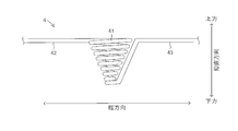
- FIG. 3 is a front view of the basket filament heater as viewed from the right side of FIG.
- FIG. 4 is a perspective view of the basket filament heater.
- FIG. 5 is a view showing the basket filament heater in a state where the vapor deposition material is accommodated in the accommodating portion and the reflection plate according to the first embodiment is disposed.
- FIG. 6 is a perspective view of the basket filament heater showing a state in which the vapor deposition material is accommodated in the accommodating portion and the reflector according to the first embodiment is disposed.
- FIG. 1 is a schematic cross-sectional view of a vertical vapor deposition apparatus as seen from the plane direction.
- FIG. 2 is a cross-sectional view taken along the line AA in FIG.
- FIG. 3 is a front view of the basket filament heater as viewed from
- FIG. 7 is a perspective view of the basket filament heater showing a state in which the vapor deposition material is removed from FIG.
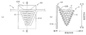
- FIG. 8 is a view showing a basket filament heater to which a reflector according to the second embodiment is attached.
- FIG. 9 is a view showing a basket filament heater to which the reflector according to the third embodiment is attached.
- FIG. 10 is a view showing a basket filament heater to which a reflector according to the fourth embodiment is attached.
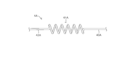
- FIG. 11 is a front view of the coil filament heater.
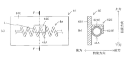
- FIG. 12 is a view showing a coil filament heater to which the reflector according to the fifth embodiment is attached.
- FIG. 1 is a schematic cross-sectional view of the vertical vapor deposition apparatus 1 according to the first embodiment as seen from the plane direction.
- FIG. 2 is a cross-sectional view taken along the line AA in FIG.
- FIG. 2 is a schematic cross-sectional view of the vertical vapor deposition apparatus 1 according to the present embodiment as viewed from the side.
- the left-right direction is defined as the front-rear direction
- the right is defined as the front
- the left is defined as the rear.
- the vertical direction is defined as the width direction.
- the up-down direction in FIG. 2 is a vertical direction (gravity direction).
- the front-rear direction and the width direction are directions perpendicular to the vertical direction, that is, horizontal directions.
- the direction used for the description of the vapor deposition apparatus and each component included in the vapor deposition apparatus is the direction defined as described above.
- the vertical deposition apparatus 1 includes a vacuum chamber 2, a holding unit 3, a basket filament heater 4, and a power source 5.
- the vacuum chamber 2 is a housing in which a space is formed.
- a holding unit 3 and a basket filament heater 4 are disposed in the vacuum chamber 2.
- the vacuum chamber 2 is configured so that the internal space can be in a high vacuum state.
- the holding unit 3 is provided at a predetermined position in the vacuum chamber 2.
- the substrate W is held by the holding unit 3.
- the substrate W has a vapor deposition surface S on which a thin film is to be formed.
- the vapor deposition surface S is arranged along the vertical direction as shown in FIG. That is, in the base material W, the normal direction of the vapor deposition surface S is the horizontal direction so that the vapor deposition surface S is arranged in parallel to the vertical direction, that is, perpendicular to the horizontal direction (front-rear direction). In this way, it is held by the holding unit 3.
- the basket filament heater 4 is composed of a linear heating element and generates heat when energized. Tungsten is typically used as the heating element.
- FIG. 3 is a front view of the basket filament heater 4 disposed in the vacuum chamber 2 as viewed from the right side (front side) of FIG. As shown in FIG. 3, the basket filament heater 4 includes a storage portion 41, a first straight portion 42, and a second straight portion 43, and is configured by a single linear heating element.
- the accommodating portion 41 is formed by bending a linear heating element.
- the accommodating portion 41 is wound in a spiral shape (more specifically, a conical spiral shape) by winding a linear heating element so that its outer shape becomes a conical shape that protrudes downward. Formed.
- the container portion 41 of the basket filament heater 4 formed in this way is shaped like a goal net hung on a basket goal ring.
- the end of the linear heating element located at the upper end of the accommodating portion 41 formed in a downwardly convex conical shape is connected to one end of the first linear portion 42 formed in a straight line. Further, the end of the linear heating element located at the lower end of the accommodating portion 41 is connected to one end of the second straight portion 43 formed in a straight line.
- the first straight portion 42 and the second straight portion 43 each extend in the opposite direction from the connection position with the accommodating portion 41. Accordingly, as shown in FIG. 1, the accommodating portion 41 is arranged in the vacuum chamber 2 so as to have a downwardly convex conical shape while being suspended between the first straight portion 42 and the second straight portion 43. Established.
- the accommodating part 41 is arrange
- the accommodating portion 41 is disposed at a position away from the vapor deposition surface S of the base material W held by the holding portion 3 by a predetermined distance.
- the basket filament heater 4 is disposed in the vacuum chamber 2 so that the accommodating portion 41 is positioned at a predetermined distance in the horizontal direction (backward) with respect to the base material W held by the holding portion 3. It is arranged.
- the other end portion side of the first straight portion 42 and the other end portion side of the second straight portion 43 are each drawn out from the vacuum chamber 2 and disposed outside the vacuum chamber 2 as shown in FIG. Connected to power supply 5.
- the power source 5 has a plus terminal 5a and a minus terminal 5b.
- the other end of the first straight portion 42 is connected to the plus terminal 5a of the power source 5, and the other end of the second straight portion 43 is a power source. 5 is connected to the negative terminal 5b.
- FIG. 4 is a schematic perspective view of the basket filament heater 4.
- the linear heating element constituting the accommodating portion 41 of the basket filament heater 4 is wound in a conical spiral shape so that the diameter decreases toward the lower side. Since the linear heating element constituting the housing part 41 only forms a framework of the side circumferential surface of the housing part 41, gaps are formed everywhere on the side circumferential surface of the housing part 41. Specifically, a gap is formed between adjacent windings along the vertical direction. In addition, a large opening is formed on the upper surface side of the accommodating portion 41 and a small opening is formed on the lower surface side.
- a solid deposition material V is accommodated in the accommodating portion 41 of the basket filament heater 4.
- the accommodating part 41 is formed so that the vapor deposition material V can be accommodated by winding a linear heating element in a spiral shape (conical spiral shape).
- the vapor deposition material V is a thin film material to be formed on the vapor deposition surface S of the substrate W.
- the vapor deposition material V is not particularly limited as long as it can be deposited on the vapor deposition surface S of the substrate W by a resistance heating type vapor deposition method.
- the vapor deposition material V may be formed in a lump shape, a pellet shape, or a particle shape so that it can be accommodated in the accommodating portion 41.
- the size of the vapor deposition material V may be an appropriate size so as not to spill from the gap of the storage portion 41 when stored in the storage portion 41.
- FIG. 5 is a view showing the basket filament heater 4 in a state where the vapor deposition material V is accommodated in the accommodating portion 41 and the reflecting plate 6A is disposed, and FIG. 5 (a) is viewed from the front.
- FIG. 5B is a sectional view taken along the line BB of FIG. 5A.
- the left-right direction is the front-back direction
- the right side is the front
- the left is the back.
- the vapor deposition material V accommodated in the accommodating part 41 is shown with the broken line.
- the reflector 6 ⁇ / b> A is disposed behind the vapor deposition material V in the accommodating portion 41.
- the base material W held by the holding portion 3 is arranged in front of the housing portion 41. That is, when viewed from the base material W held by the holding unit 3, the reflecting plate 6 ⁇ / b> A is disposed behind the vapor deposition material V in the storage unit 41.
- the reflecting plate 6 ⁇ / b> A is in contact with the linear heating element constituting the housing portion 41 in the housing portion 41. For this reason, when the basket filament heater 4 generates heat, the heat from the basket filament heater 4 is transmitted to the reflector 6A.
- FIG. 6 is a schematic perspective view of the basket filament heater 4 showing a state in which the vapor deposition material V is accommodated in the accommodating portion 41 and the reflecting plate 6A is disposed.
- FIG. 7 is a schematic perspective view of the basket filament heater 4 showing a state in which the vapor deposition material V is removed from FIG.
- the reflector 6A is formed in a semi-conical shape along the side peripheral surface of the conical housing portion 41, and is formed in the housing portion 41 so as to protrude downward.
- the reflecting plate 6 ⁇ / b> A is disposed in the housing portion 41 so as to come into contact with a linear heating element constituting the rear side surface of the housing portion 41. Therefore, the reflecting plate 6 ⁇ / b> A is disposed in the housing part 41 so as to cover the vapor deposition material V housed in the housing part 41 from behind in the housing part 41.
- the reflector 6A is formed of a material that does not melt by the heat of the basket filament heater 4.
- Examples of the material of the reflector 6A include tungsten (W), tantalum (Ta), molybdenum (Mo), molybdenum lanthanum alloy (Mo—La), platinum (Pt), and nichrome (Ni—Cr). Of these, molybdenum, tungsten, and tantalum are preferable as the material of the reflector 6A.
- the base material W is held by the holding unit 3 provided in the vacuum chamber 2.
- the reflection plate 6 ⁇ / b> A is disposed in the accommodating portion 41 of the basket filament heater 4 provided in the vacuum chamber 2.
- the reflecting plate 6A is disposed in the accommodating portion 41 so that the reflecting plate 6A covers a half side surface forming the rear portion of the side peripheral surface of the accommodating portion 41.
- the vapor deposition material V is accommodated in the accommodating portion 41.
- the reflector 6 ⁇ / b> A is disposed on the rear side of the vapor deposition material V in the accommodating portion 41.
- the vacuum chamber 2 is evacuated to make the vacuum chamber 2 in a high vacuum state. Thereafter, the power source 5 is activated. Then, the basket filament heater 4 is energized and the basket filament heater 4 generates heat. Thereby, the vapor deposition material V and the reflecting plate 6 ⁇ / b> A in the accommodating portion 41 of the basket filament heater 4 are heated.
- the vapor deposition material V in the housing part 41 When the vapor deposition material V in the housing part 41 is heated, the vapor deposition material V evaporates. For this reason, vapor is generated from the vapor deposition material V.
- the generated steam travels in all directions through the gap, the upper opening, and the lower opening formed on the side peripheral surface of the accommodating portion 41.
- the steam that has traveled forward that is, the steam that travels in the direction toward the substrate W held by the holding unit 3 contacts the deposition surface S of the substrate W as it is. Then, it is cooled by the vapor deposition surface S and solidifies at that position.
- the steam that has traveled backward contacts the reflector 6A.
- the reflecting plate 6A is heated by the heat from the basket filament type heater 4, the vapor that has contacted the reflecting plate 6A is reflected by the reflecting plate 6A without being cooled.
- the vapor that has come into contact with the reflecting plate 6A is once solidified by the reflecting plate 6A and then re-evaporated by the heat of the reflecting plate 6A.
- the vapor that has been reflected or re-evaporated reverses the traveling direction, moves forward, contacts the vapor deposition surface S of the substrate W, is cooled by the vapor deposition surface S, and solidifies at that position.
- a thin film is formed on the deposition surface S by minute solid particles solidified on the deposition surface S being uniformly deposited on the deposition surface S.
- the vapor traveling in the direction toward the substrate (front) and the vapor traveling in the direction opposite to the direction toward the substrate (rear). Contributes to vapor deposition on the vapor deposition surface S of the substrate W. That is, vapor traveling in a plurality of directions contributes to vapor deposition. Therefore, the yield of the vapor deposition material can be improved.
- the reflecting plate 6 ⁇ / b> A is disposed in the accommodating portion 41 of the basket filament heater 4. For this reason, the reflecting plate 6A can be easily heated by the heat from the basket filament heater 4. Further, since the reflecting plate 6A is disposed in the accommodating portion 41, the reflecting plate can be held at the rear position of the vapor deposition material, and therefore a separate holding member or the like for holding the reflecting plate is not required. Therefore, the vertical evaporation apparatus 1 can be configured more simply.
- FIG. 8A and 8B are views showing the basket filament heater 4 to which the reflector 6B according to the second embodiment is attached.
- FIG. 8A is a front view seen from the front, and FIG. 8B is FIG. It is CC sectional drawing of a).
- the left-right direction is the front-rear direction, the right is the front, and the left is the rear.
- the reflecting plate 6B according to the second embodiment includes a back plate 61B and a connecting portion 62B.
- the back plate 61 ⁇ / b> B is disposed not behind the housing part 41 of the basket filament heater 4 but behind the housing part 41.
- the back plate 61B is flat and has a rectangular shape when viewed from the front.
- connecting portion 62B is coupled to the upper end of the back plate 61B.
- the connecting portion 62B extends obliquely forward and downward from the upper end of the back plate 61B, and its outer shape is triangular as viewed from the direction shown in FIG.
- the tip end portion of the connecting portion 62 B is hung from above on a linear heating element constituting the accommodating portion 41 of the basket filament heater 4.
- the connecting portion 62B is hung on the accommodating portion 41, the back plate 61B is connected to the basket filament heater 4 via the connecting portion 62B. Therefore, the back plate 61B is supported by the housing portion 41 in a state where the back plate 61B is disposed at the rear position of the housing portion 41, and heat from the basket filament heater 4 is transmitted to the back plate 61B via the connection portion 62B.
- the vapor deposition material V accommodated in the accommodating portion 41 is indicated by a broken line.
- the vertical vapor deposition apparatus 1 including the reflection plate 6 ⁇ / b> B having the above-described configuration when the basket filament heater 4 is heated to heat the vapor deposition material V in the storage unit 41, vapor is generated from the vapor deposition material V in the storage unit 41. .
- steam which progressed back contacts the back plate 61B of the reflecting plate 6B arrange
- the back plate 61B is connected to the basket filament heater 4 via the connecting portion 62B, the back plate 61B is heated by transferring the heat of the basket filament heater 4. For this reason, the vapor contacted with the back plate 61B is reflected without being solidified by the back plate 61B, or is once again solidified by the back plate 61B and then re-evaporated.
- the vapor that has been reflected or re-evaporated reverses the traveling direction, moves forward, contacts the vapor deposition surface S of the substrate W, is cooled by the vapor deposition surface S, and solidifies at that position.
- a thin solid film is formed on the vapor deposition surface S by minute solid particles solidified on the vapor deposition surface S being uniformly deposited on the vapor deposition surface S.
- This contributes to vapor deposition on the vapor deposition surface S of the substrate W. That is, vapor traveling in a plurality of directions contributes to vapor deposition. Therefore, the yield of the vapor deposition material can be improved.
- the vapor deposition apparatus which concerns on 3rd embodiment is the said 1st embodiment only in arrangement
- other configurations are the same as those in the first embodiment. Accordingly, only the arrangement and shape of the reflector will be described, and the description of the other components will be omitted.
- FIG. 9 is a view showing the basket filament heater 4 to which the reflector 6C according to the third embodiment is attached.
- FIG. 9 (a) is a front view seen from the front
- FIG. 9 (b) is FIG. It is DD sectional drawing of a).
- the left-right direction is the front-rear direction
- the right is the front
- the left is the rear.
- the reflector 6C according to the third embodiment also includes a back plate 61C and a connecting portion 62C, similarly to the reflector 6B according to the second embodiment.
- the back plate 61 ⁇ / b> C is disposed behind the housing portion 41.
- the back plate 61C has a flat plate shape and has a rectangular shape when viewed from the front.
- a notch L is formed in a part of the back plate 61C
- a connection part 62C is formed by pushing the part cut out by the notch L forward.
- the connecting portion 62 ⁇ / b> C extends obliquely forward and downward from the back plate 61 ⁇ / b> C, and its tip portion constitutes the accommodating portion 41 of the basket filament heater 4.
- a linear heating element is hung from above.
- the connecting portion 62C By connecting the connecting portion 62C to the housing portion 41, the back plate 61C is connected to the basket filament heater 4 via the connecting portion 62C.
- the back plate 61C is supported by the housing portion 41 in a state of being disposed at the rear position of the housing portion 41, and the heat from the basket filament heater 4 is transmitted to the back plate 61C via the connection portion 62C.
- the vapor deposition material V accommodated in the accommodating portion 41 is indicated by a broken line.
- the vapor traveling in the direction toward the substrate (front) and the direction opposite to the direction toward the substrate (backward) Contributes to vapor deposition on the vapor deposition surface S of the substrate W. That is, vapor traveling in a plurality of directions contributes to vapor deposition. Therefore, the yield of the vapor deposition material can be improved.
- FIG. 10 is a view showing the basket filament heater 4 to which the reflector 6D according to the fourth embodiment is attached.
- FIG. 10 (a) is a front view seen from the front
- FIG. 10 (b) is FIG. It is EE sectional drawing of a).
- the left-right direction is the front-back direction
- the right side is the front
- the left is the back.
- the reflector 6D according to the fourth embodiment includes a back plate 61D, a connecting portion 62D, an upper plate 63D, and a lower plate 64D.
- the back plate 61D is disposed behind the accommodating portion 41 in the same manner as the back plates 61B and 61C according to the second and third embodiments.
- the back plate 61D is flat and has a rectangular shape when viewed from the front.
- a notch L is formed in a part of the back plate 61D, and the connection part 62D is formed by pushing out the part cut out by the notch L forward.
- the connecting portion 62 ⁇ / b> D extends obliquely forward and downward from the back plate 61 ⁇ / b> D, and its tip portion constitutes the accommodating portion 41 of the basket filament heater 4.
- a linear heating element is hung from above.
- the back plate 61D When the connecting portion 62D is hung on the housing portion 41, the back plate 61D is connected to the basket filament heater 4 via the connecting portion 62D. For this reason, the back plate 61D is supported by the housing portion 41 in a state of being disposed at the rear position of the housing portion 41, and heat from the basket filament heater 4 is transmitted to the back plate 61D via the connection portion 62D.
- the upper plate 63D is connected to the upper end of the back plate 61D
- the lower plate 64D is connected to the lower end of the back plate 61D.
- the upper plate 63D extends forward from the upper end of the rear plate 61D, and covers the accommodating portion 41 from the upper side.
- the lower plate 64D extends forward from the lower end of the back plate 61D, and covers the accommodating portion 41 from the lower side. Therefore, in the present embodiment, the rear side, the upper side, and the lower side of the accommodating portion 41 are surrounded by the reflecting plate 6D. Since the upper plate 63D and the lower plate 64D are respectively connected to the back plate 61D as described above, heat from the basket filament heater 4 is transferred to the upper plate 63D and the lower plate 64D via the back plate 61D. Is also communicated.
- the vertical vapor deposition apparatus 1 including the reflection plate 6D having the above-described configuration among the vapors generated from the vapor deposition material V in the accommodating portion 41, the vapor traveling forward contacts the vapor deposition surface S of the substrate W, and the vapor deposition surface S And is solidified at that position. Moreover, the vapor
- the vapor reflected or re-evaporated by the back plate 61D reverses the traveling direction, moves forward, contacts the vapor deposition surface S of the substrate W, is cooled by the vapor deposition surface S, and solidifies at that position.
- steam which progressed upwards from the accommodating part 41 is reflected or re-evaporated by the upper board 63D by the upper board 63D of the reflecting plate 6D arrange
- the vapor reflected or re-evaporated by the upper plate 63D changes the traveling direction, moves forward, contacts the vapor deposition surface S of the substrate W, is cooled by the vapor deposition surface S, and is solidified at that position.
- steam which progressed below from the accommodating part 41 is reflected by the lower board 64D of the reflecting plate 6D arrange
- the vapor reflected or re-evaporated by the lower plate 64D changes the traveling direction, moves forward, contacts the vapor deposition surface S of the substrate W, is cooled by the vapor deposition surface S, and is solidified at that position.
- a thin solid film is formed on the vapor deposition surface S by minute solid particles solidified on the vapor deposition surface S being uniformly deposited on the vapor deposition surface S.
- the vapors traveling in a plurality of directions are used for vapor deposition on the vapor deposition surface S of the substrate W. Contribute. That is, vapor traveling in a plurality of directions contributes to vapor deposition. Therefore, the yield of the vapor deposition material can be further improved.
- the vapor deposition apparatus according to the fifth embodiment is different from the first embodiment in the shape of the filament heater, the arrangement and shape of the reflector, and other configurations. Is the same as in the first embodiment. Therefore, it demonstrates centering on difference and the description about another structure is abbreviate
- FIG. 11 is a front view of a coil filament heater 4A used in the present embodiment.
- the coil filament heater 4A includes a storage portion 41A formed in a cylindrical shape by bending a linear heating element in a spiral shape, and a first straight portion 42A connected to one end of the cylindrical storage portion 41A. And a second linear portion 43A connected to the other end of the cylindrical accommodating portion 41A.
- the vapor deposition material is accommodated in the accommodating portion 41A.
- the coil filament heater 4A is disposed in the vacuum chamber 2 so that the central axis direction of the cylindrical accommodating portion 41A is parallel to the width direction.
- the first straight line portion 42A is connected to the plus terminal 5a of the power source 5, and the second straight line portion 43A is connected to the minus terminal 5b of the power source 5.
- the reflector 6E is attached to the coil filament heater 4A having the above shape.
- 12A and 12B are views showing the coil filament heater 4A to which the reflector 6E is attached.
- FIG. 12A is a front view seen from the front
- FIG. 12B is an FF in FIG. It is sectional drawing.
- the left-right direction is the front-rear direction
- the right is the front
- the left is the rear.
- the reflecting plate 6E has a back plate 61E and a connecting portion 62E.
- the back plate 61E is disposed behind the accommodating portion 41A of the coil filament heater 4A, and the outer shape thereof is a rectangular shape when viewed from the front.
- a notch L is formed in a part of the back plate 61E, and a connection part 62E is formed by pushing the part cut out by the notch L forward.
- the connecting portion 62E includes a first portion 621E extending forward from the back plate 61E, and a second portion 622E extending downward from the tip (front end) of the first portion 621E. And is formed in a cross-sectional shape (L-shaped) as viewed from the direction shown in FIG.
- the connecting portion 62E is hung on the accommodating portion 41A so that the first portion 621E is in contact with the upper surface of the accommodating portion 41A and the second portion 622E is in contact with the front surface of the accommodating portion 41A.
- the connecting portion 62E is hung on the housing portion 41A, the back plate 61E is connected to the coil filament heater 4A via the connecting portion 62E.
- the back plate 61E is supported by the housing portion 41A in a state of being disposed at the rear position of the housing portion 41A, and heat from the coil filament heater 4A is transmitted to the back plate 61E via the connection portion 62E.
- the vapor traveling forward from the vapor generated from the vapor deposition material V in the accommodating portion 41A contacts the vapor deposition surface S of the substrate W and is cooled by the vapor deposition surface S. It solidifies at the position.
- steam which progressed back is reflected in contact with the backplate 61E of the reflecting plate 6E arrange
- the vapor that has been reflected or re-evaporated reverses the traveling direction, moves forward, contacts the vapor deposition surface S of the substrate W, is cooled by the vapor deposition surface S, and solidifies at that position.
- a thin solid film is formed on the vapor deposition surface S by minute solid particles solidified on the vapor deposition surface S being uniformly deposited on the vapor deposition surface S.
- the vapor traveling in the direction (front) toward the substrate and the vapor traveling in the direction (rear) opposite to the direction toward the substrate are vapor deposition of the substrate W.
- Example 1 Solid indium was accommodated in the accommodating part of the basket filament heater made of tungsten. Further, the reflector 6A (material: molybdenum) according to the first embodiment is disposed in the housing portion and at the rear position of the solid indium. And the indium thin film was vapor-deposited on the surface (deposition surface) of the resin-made base materials using the vertical vacuum evaporation system. (Example 2) Solid indium was accommodated in the accommodating part of the basket filament heater made of tungsten. Further, the reflector 6B (material: molybdenum) according to the second embodiment was attached to the basket filament heater. And the indium thin film was vapor-deposited on the surface (deposition surface) of the resin-made base materials using the vertical vacuum evaporation system.
- Example 3 Solid indium was accommodated in the accommodating part of the basket filament heater made of tungsten. Further, the reflector 6B (material: tungsten) according to the second embodiment was attached to the basket filament heater. And the indium thin film was vapor-deposited on the surface (deposition surface) of the resin-made base materials using the vertical vacuum evaporation system.
- Example 4 Solid indium was accommodated in the accommodating part of the basket filament heater made of tungsten. Further, the reflector 6B (material: tantalum) according to the second embodiment was attached to the basket filament heater. And the indium thin film was vapor-deposited on the surface (deposition surface) of the resin-made base materials using the vertical vacuum evaporation system.
- Example 5 Solid indium was accommodated in the accommodating part of the basket filament heater made of tungsten. Further, the reflector 6C (material: molybdenum) according to the third embodiment was attached to the basket filament heater. And the indium thin film was vapor-deposited on the surface (deposition surface) of the resin-made base materials using the vertical vacuum evaporation system. (Example 6) Solid indium was accommodated in the accommodating part of the basket filament heater made of tungsten. Further, the reflector 6D (material: molybdenum) according to the fourth embodiment was attached to the basket filament heater. And the indium thin film was vapor-deposited on the surface (deposition surface) of the resin-made base materials using the vertical vacuum evaporation system.
- Example 1 The indium thin film is deposited on the surface (deposition surface) of the resin base material using a vertical vacuum deposition device without containing a reflector and containing solid indium in the basket basket type heater housing made of tungsten. did.
- Example 7 Solid indium was accommodated in the accommodating portion of the tungsten coil filament heater. Further, the reflector 6E (material: molybdenum) according to the fifth embodiment was attached to a coil filament heater. And the indium thin film was vapor-deposited on the surface (deposition surface) of the resin-made base materials using the vertical vacuum evaporation system.
- Table 1 shows the type of filament heater used, the presence or absence of the reflector, the form and arrangement of the reflector, and the material in each example.
- the vertical vacuum deposition apparatus used is model VRD500ADP1 manufactured by Shin Meiwa Kogyo Co., Ltd.
- the film formation conditions film formation time, degree of vacuum in the vacuum chamber, heating temperature of the filament heater, etc. are the same.
- the thickness of the indium thin film formed in each example was measured using a quartz vibration type film thickness meter (manufactured by Inficon Corporation: XTCS-1000). And the film thickness ratio in each example was computed.
- the film thickness ratio is the ratio of the film thickness measured in the example when the film thickness measured in the comparative example is 100.
- the film thickness ratio is calculated when the film thickness of Comparative Example 1 is 100.
- Example 7 the film thickness ratio when the film thickness of Comparative Example 2 is 100 is calculated.
- the temperature of the substrate surface (deposition surface) during film formation was measured using a contact thermometer (manufactured by Rika Kogyo Co., Ltd .: DP-500). Table 2 shows the measurement results of the film thickness ratio and the substrate surface temperature calculated in each example.
- the reflector is heated by the heat of the filament heater, but if the heat of the reflector is transmitted to the substrate and the substrate is excessively heated, the substrate is thermally deteriorated. There is a risk of causing.
- the reflecting plate is disposed at a position close to the base material, there is a high possibility that the base material is thermally deteriorated by the heat of the reflecting plate.
- Patent Document 1 and Patent Document 2 when a reflective plate heated so as to surround a space from the vapor deposition material to the base material is arranged, that is, when viewed from the base material, it is heated in front of the vapor deposition material.
- the heated reflector is disposed behind the vapor deposition material, that is, at a position away from the substrate when viewed from the vapor deposition material.
- the heated reflector is not disposed in front of the vapor deposition material as viewed from the substrate. For this reason, it is difficult for the heat of a reflecting plate to be transmitted to a base material. Therefore, as shown in Table 2, in each example, the substrate surface temperature during film formation is about 50 ° C. to 60 ° C., which is lower than the heat deformation temperature of a general resin substrate. For this reason, the thermal deterioration of the base material by the heat
- the present invention should not be limited to the above-described embodiments and examples.
- a basket filament type heater and a coil filament type heater are used as the filament type heater.
- the storage unit is configured by a linear heating element and is formed by bending the linear heating element. Any filament type heater having a portion can be applied to the present invention.
- the filament heater is made of tungsten.
- the filament heater can be made of other materials that can be used as a heater.
- the present invention can be modified without departing from the gist thereof.
Landscapes
- Chemical & Material Sciences (AREA)
- Chemical Kinetics & Catalysis (AREA)
- Engineering & Computer Science (AREA)
- Materials Engineering (AREA)
- Mechanical Engineering (AREA)
- Metallurgy (AREA)
- Organic Chemistry (AREA)
- Physical Vapour Deposition (AREA)
Abstract
縦型蒸着装置は、基材を保持する保持部と、通電することにより発熱する線状の発熱体により構成され、線状の発熱体を折り曲げることにより蒸着材料を収容することができるように形成された収容部を有し、保持部に保持されている基材に対して水平方向に所定の距離だけ離間して収容部が位置するように配設されたバスケットフィラメント型ヒータと、保持部に保持されている基材から見て、収容部に収容されている蒸着材料の後方に配設されるとともに、バスケットフィラメント型ヒータから熱が伝達されるように構成された反射板と、を備える。
Description
本発明は、蒸着装置に関する。
基材表面に薄膜を成膜させるために用いられる蒸着装置は、基材を保持する保持部と、固体状の蒸着材料を加熱するためのヒータと、を備える。ヒータの熱で蒸着材料が加熱されることにより、蒸着材料から蒸気が発生する。発生した蒸気は、保持部に保持された基材表面(蒸着面)に接触し、接触部位で冷却されることにより凝固する。こうして凝固した微小の固体粒子が蒸着面に均一に蒸着することにより、蒸着面に薄膜が成膜される。
特許文献1及び特許文献2は、蒸着材料から基材に至る空間を取り囲むように反射板が配設されるとともに、この反射板を加熱するように構成された蒸着装置を開示する。特許文献1及び特許文献2に記載の蒸着装置によれば、蒸着材料から蒸発した蒸気が反射板に接触する。反射板に接触した蒸気は反射板上で凝固して固体粒子を形成する。この固体粒子は、反射板上で加熱されることにより再蒸発する。再蒸発した蒸気を基材の蒸着面に接触させることにより、蒸着材料の収率(蒸着効率)を向上させることができる。
(発明が解決しようとする課題)
特許文献1及び特許文献2に開示の蒸着装置によれば、いずれも、上面のみが開口した耐熱容器に蒸着材料が投入される。そして、耐熱容器がヒータにより加熱されることによって、耐熱容器内部の蒸着材料が加熱されて、蒸着材料から蒸気が発生する。このとき、蒸着材料が収容された耐熱容器の上面が開口しているため、蒸着材料からの蒸気は基本的に上方に進行する。従って、上方に進行する蒸気が接触される基材表面(蒸着面)は、蒸気の進行方向に垂直な方向、即ち水平方向(横方向)に平行に配置される。このような蒸着面が水平方向に平行配置するように基材が保持部に保持される蒸着装置は、横型蒸着装置と呼ばれる。一方、蒸着面が鉛直方向に平行配置するように基材が保持部に保持される蒸着装置は、縦型蒸着装置と呼ばれる。
特許文献1及び特許文献2に開示の蒸着装置によれば、いずれも、上面のみが開口した耐熱容器に蒸着材料が投入される。そして、耐熱容器がヒータにより加熱されることによって、耐熱容器内部の蒸着材料が加熱されて、蒸着材料から蒸気が発生する。このとき、蒸着材料が収容された耐熱容器の上面が開口しているため、蒸着材料からの蒸気は基本的に上方に進行する。従って、上方に進行する蒸気が接触される基材表面(蒸着面)は、蒸気の進行方向に垂直な方向、即ち水平方向(横方向)に平行に配置される。このような蒸着面が水平方向に平行配置するように基材が保持部に保持される蒸着装置は、横型蒸着装置と呼ばれる。一方、蒸着面が鉛直方向に平行配置するように基材が保持部に保持される蒸着装置は、縦型蒸着装置と呼ばれる。
縦型蒸着装置を用いて基材表面(蒸着面)に薄膜を成膜する場合、蒸着面が鉛直方向に平行配置するように基材が保持部に保持されるのであるから、この蒸着面に接触する蒸気の進行方向は、蒸着面の垂直方向、すなわち水平方向である。この場合、一般的には、蒸着材料を加熱させるためのヒータとしてフィラメント型ヒータが用いられる。
フィラメント型ヒータは、通電することにより発熱する線状の発熱体により構成されるとともに、蒸着材料を収容することができるように形成された収容部を有する。フィラメント型ヒータが発熱した場合、収容部内に収容された蒸着材料が加熱されることにより、蒸着材料から蒸気が発生する。この収容部は、線状の発熱体を折り曲げることにより形成されている。そのため、収容部を構成する線状の発熱体とそれに隣接する線状の発熱体との間に隙間が形成される。つまり、収容部には、多くの隙間が形成される。従って、フィラメント型ヒータが発熱して収容部に収容された蒸着材料から蒸気が発生した場合、その蒸気は収容部に形成された隙間を通過して全方位に進行する。
このように、フィラメント型ヒータを用いることにより、蒸着材料から生じた蒸気を全方位に進行させることができるため、全方位に進行した蒸気のうち基材に向かう水平方向に進行した蒸気を蒸着面に接触させることにより、蒸着面に薄膜を成膜することができる。
しかしながら、フィラメント型ヒータを用いた場合、蒸着材料から見て基材に向かう方向に進行した蒸気は蒸着面に接触するが、それ以外の方向に進行した蒸気は蒸着面に接触しない。すなわち、単一の方向に進行する蒸気のみが蒸着に寄与し、それ以外の方向に進行する蒸気は蒸着に寄与しない。よって、フィラメント型ヒータを用いた場合、蒸着材料の収率が極めて低いという問題を有する。
本発明は、蒸着材料の収率を高めるように構成された、フィラメント型ヒータを用いた蒸着装置を提供することを目的とする。
(課題を解決するための手段)
本発明は、基材(W)を保持する保持部(3)と、通電することにより発熱する線状の発熱体により構成され、線状の発熱体を折り曲げることにより蒸着材料を収容することができるように形成された収容部(41,41A)を有し、保持部に保持されている基材に対して水平方向に所定の距離だけ離間して収容部が位置するように配設されたフィラメント型ヒータ(4,4A)と、保持部に保持されている基材から見て、収容部に収容されている蒸着材料の後方に配設されるとともに、フィラメント型ヒータから熱が伝達されるように構成された反射板(6A,6B,6C,6D,6E)と、を備える、蒸着装置(1)を提供する。
本発明は、基材(W)を保持する保持部(3)と、通電することにより発熱する線状の発熱体により構成され、線状の発熱体を折り曲げることにより蒸着材料を収容することができるように形成された収容部(41,41A)を有し、保持部に保持されている基材に対して水平方向に所定の距離だけ離間して収容部が位置するように配設されたフィラメント型ヒータ(4,4A)と、保持部に保持されている基材から見て、収容部に収容されている蒸着材料の後方に配設されるとともに、フィラメント型ヒータから熱が伝達されるように構成された反射板(6A,6B,6C,6D,6E)と、を備える、蒸着装置(1)を提供する。
本発明によれば、フィラメント型ヒータへの通電によりフィラメント型ヒータが発熱すると、その熱がフィラメント型ヒータの収容部内に収容された蒸着材料に伝達される。このため蒸着材料が加熱され、蒸着材料から蒸気が発生する。この蒸気は全方位に進行するが、そのうち蒸着材料から見て保持部に保持されている基材に向かう方向に進行する蒸気は基材の蒸着面に接触し、接触部位で凝固する。また、全方位に進行する蒸気のうち蒸着材料から見て保持部に保持されている基材に向かう方向とは反対方向に進行する蒸気は、保持部に保持されている基材から見て蒸着材料の後方に配設された反射板に接触する。反射板は、フィラメント型ヒータからの熱が伝達されることによって加熱されているので、反射板に接触した蒸気は反射板上で凝固しない。或いは、反射板上で一旦凝固しても、凝固した固体粒子が反射板の熱で再蒸発される。このため、反射板に接触した蒸気は反射板に反射され或いは反射板にて再蒸発されることにより進行方向を反転させて、基材に向かう。そして、基材の蒸着面に接触し、接触部位で凝固する。
すなわち、本発明によれば、蒸着材料から生じた蒸気のうち、基材に向かう方向に進行する蒸気及び基材に向かう方向とは反対方向に進行する蒸気が、蒸着面での蒸着に寄与する。このように、蒸着材料から複数の方向に進行する蒸気が蒸着に寄与するため、フィラメント型ヒータを用いた場合における蒸着材料の収率を向上させることができる。
本発明において、反射板(6A)は、収容部内に配設されているとよい。この場合、反射板は、収容部内であって、収容部内に収容されている蒸着材料よりも、保持部に保持されている基材から見て後方の位置に配設される。また、収容部(41)は、線状の発熱体を螺旋状に巻回することにより、その外形形状が下に凸の円錐形状となるように形成されるとよい。そして、反射板(6A)は、半円錐形状に形成されていて、下に凸となるように収容部内に配設されているとよい。上記構成によれば、反射板がフィラメント型ヒータの収容部内に配設されているため、フィラメント型ヒータからの熱を容易に反射板に伝達することができる。また、反射板を収容部内に配設することにより反射板を蒸着材料の後方位置に保持することができるため、反射板を所定位置にて保持するための保持部材等を別途必要としない。よって、より簡素に、本発明に係る蒸着装置を構成することができる。
また、反射板(6B,6C,6D,6E)は、保持部に保持されている基材からみて収容部の後方に配設された背面板(61B,61C,61D,61E)を有していてもよい。この場合、反射板は、背面板が収容部に保持されるとともにフィラメント型ヒータからの熱が背面板に伝達されるように、背面板とフィラメント型ヒータとを接続する接続部(62B,62C,62D,62E)をさらに備えているとよい。これによれば、収容部内に収容されている蒸着材料からの蒸気のうち、基材に向かう方向とは反対方向に進行する蒸気を収容部の後方に配設された背面板で反射或いは反射板にて再蒸発させて基材に向かう方向に進行させることにより、蒸着材料の収率を向上させることができる。
また、反射板(6D)は、収容部の上方に配設された上板(63D)及び収容部の下方に配設された下板(64D)を有するとよい。これによれば、フィラメント型ヒータの収容部内の蒸着材料から生じて全方位に進行する蒸気のうち収容部の上方に進行する蒸気及び下方に進行する蒸気を上板及び下板で反射或いは上板及び下板にて再蒸発させて基材に向かう方向に進行させることにより、蒸着材料の収率をより向上させることができる。
(第一実施形態)
本発明の実施形態に係る蒸着装置について、図面を参照して説明する。図1は、第一実施形態に係る縦型蒸着装置1を平面方向から見た模式的な断面図である。また、図2は、図1のA-A断面図である。図2は、本実施形態に係る縦型蒸着装置1を側面方向から見た模式的な断面図である。なお、図1及び図2において、左右方向を前後方向と定義し、右方を前方、左方を後方と定義する。また、図1において上下方向を幅方向と定義する。また、図2における上下方向は鉛直方向(重力方向)である。前後方向及び幅方向は、鉛直方向に垂直な方向、すなわち水平方向である。以下の説明において、蒸着装置及び蒸着装置に備えられる各構成要素についての説明に用いられている方向は、上記のように定義した方向である。図1に示すように、縦型蒸着装置1は、真空槽2と、保持部3と、バスケットフィラメント型ヒータ4と、電源5とを備える。
本発明の実施形態に係る蒸着装置について、図面を参照して説明する。図1は、第一実施形態に係る縦型蒸着装置1を平面方向から見た模式的な断面図である。また、図2は、図1のA-A断面図である。図2は、本実施形態に係る縦型蒸着装置1を側面方向から見た模式的な断面図である。なお、図1及び図2において、左右方向を前後方向と定義し、右方を前方、左方を後方と定義する。また、図1において上下方向を幅方向と定義する。また、図2における上下方向は鉛直方向(重力方向)である。前後方向及び幅方向は、鉛直方向に垂直な方向、すなわち水平方向である。以下の説明において、蒸着装置及び蒸着装置に備えられる各構成要素についての説明に用いられている方向は、上記のように定義した方向である。図1に示すように、縦型蒸着装置1は、真空槽2と、保持部3と、バスケットフィラメント型ヒータ4と、電源5とを備える。
真空槽2は、内部に空間が形成された筐体である。真空槽2内に、保持部3及びバスケットフィラメント型ヒータ4が配設される。真空槽2は、その内部空間を高真空状態にすることができるように、構成される。
保持部3は、真空槽2内の所定の位置に設けられる。この保持部3に基材Wが保持される。基材Wは、薄膜が形成されるべき蒸着面Sを有する。保持部3に基材Wが保持されたとき、蒸着面Sは、図2に示すように、鉛直方向に沿って配置する。すなわち、基材Wは、蒸着面Sが鉛直方向に平行配置するように、すなわち水平方向(前後方向)に垂直であるように、さらに言えば、蒸着面Sの法線方向が水平方向であるように、保持部3に保持される。
バスケットフィラメント型ヒータ4は、線状の発熱体により構成され、通電されることにより発熱する。発熱体として、典型的にはタングステンが用いられる。図3は、真空槽2内に配設されたバスケットフィラメント型ヒータ4を図2の右方側(前方側)から見た正面図である。図3に示すように、バスケットフィラメント型ヒータ4は、収容部41と、第一直線部42と、第二直線部43とを備え、一本の線状の発熱体により構成される。
収容部41は、線状の発熱体を折り曲げることによって形成される。本実施形態において、収容部41は、線状の発熱体を螺旋状(より具体的には円錐渦巻状)に巻回することによって、その外形形状が、下に凸となる円錐形状となるように形成される。このように形成されたバスケットフィラメント型ヒータ4の収容部41は、あたかも、バスケットゴールリングに掛けられたゴールネットのような形状を呈する。
下に凸の円錐形状に形成された収容部41の上端部に位置する線状の発熱体の端部が、直線状に形成された第一直線部42の一方の端部に接続される。また、収容部41の下端部に位置する線状の発熱体の端部が、直線状に形成された第二直線部43の一方の端部に接続される。第一直線部42及び第二直線部43は、それぞれ、収容部41との接続位置から反対方向に延設する。従って、図1に示すように、収容部41は、第一直線部42と第二直線部43との間に吊り下げられた状態で下に凸の円錐形状となるように真空槽2内に配設される。このとき、収容部41は、真空槽2内にて、保持部3に保持されている基材Wから所定の距離だけ水平方向(前後方向)に離れた位置に配設される。図2においては、収容部41は、保持部3に保持されている基材Wの蒸着面Sから後方に所定距離だけ離れた位置に配設される。言い換えれば、バスケットフィラメント型ヒータ4は、保持部3に保持されている基材Wに対して水平方向(後方)に所定の距離だけ離間して収容部41が位置するように、真空槽2内に配設される。
第一直線部42の他方の端部側及び第二直線部43の他方の端部側は図1に示すようにそれぞれ真空槽2から外部に引き出されて、真空槽2の外部に配設される電源5に接続される。電源5は、プラス端子5aとマイナス端子5bとを有しており、第一直線部42の他方の端部が電源5のプラス端子5aに接続され、第二直線部43の他方の端部が電源5のマイナス端子5bに接続される。
図4は、バスケットフィラメント型ヒータ4の模式的な斜視図である。図4に示すように、バスケットフィラメント型ヒータ4の収容部41を構成する線状の発熱体は、下方に向かうにつれて径が小さくなるように円錐渦巻状に巻回されている。収容部41を構成する線状の発熱体は、収容部41の側周面の骨組みを形成しているだけであるので、収容部41の側周面のいたるところに隙間が形成される。具体的には、鉛直方向に沿って隣接する巻線間に隙間が形成される。また、収容部41の上面側に大きな開口が、下面側に小さな開口が形成される。
このバスケットフィラメント型ヒータ4の収容部41内に、固体状の蒸着材料Vが収容される。換言すれば、収容部41は、線状の発熱体を螺旋状に(円錐渦巻状に)巻回することにより、蒸着材料Vを収容することができるように形成される。蒸着材料Vは、基材Wの蒸着面Sに形成されるべき薄膜の材料である。蒸着材料Vは、抵抗加熱式の蒸着方法によって基材Wの蒸着面Sに蒸着させることができるものであれば、特に限定されない。蒸着材料として、インジウム(In)、スズ(Sn)、アルミニウム(Al)、銅(Cu)、銀(Ag)、金(Au)、鉄(Fe)、ニッケル(Ni)、クロム(Cr)、鉛(Pb)、亜鉛(Zn)、珪素(Si)、リチウム(Li)、コバルト(Co)等の、抵抗加熱式の蒸着材料として通常用いられる金属、酸化クロム(Cr2O3)、酸化亜鉛(ZnO)等の金属酸化物、若しくはこれらの合金、又は、フッ化アルミニウム(AlF3)、フッ化カルシウム(CaF2)、フッ化セリウム(CeF3)、フッ化ガドリニウム(GdF3)、フッ化ランタン(LaF3)、フッ化リチウム(LiF)、フッ化マグネシウム(MgF2)、フッ化ナトリウム(NaF)、フッ化ネオジム(NdF3)、フッ化イットリウム(YF3)等のフッ化物、硫化亜鉛(ZnS)等の硫化物、を例示することができる。
蒸着材料Vは、収容部41内に収容することができるように、塊状、ペレット状、或いは粒子状に形成されているとよい。また、蒸着材料Vの大きさは、収容部41に収容したときに収容部41の隙間からこぼれないような適度な大きさであるとよい。
また、収容部41内には、蒸着材料Vが収容されているとともに、反射板6Aが配設される。図5は、収容部41内に、蒸着材料Vが収容されているとともに反射板6Aが配設されている状態のバスケットフィラメント型ヒータ4を示す図であり、図5(a)が前方から見た正面図、図5(b)が図5(a)のB-B断面図である。図5(b)において、左右方向が前後方向であり、右方が前方、左方が後方である。なお、図5(b)において、収容部41内に収容された蒸着材料Vが、破線で示されている。
図5(b)に良く示すように、反射板6Aは、収容部41内にて、蒸着材料Vの後方に配設されている。ここで、収容部41の前方には、図2に示すように、保持部3に保持された基材Wが配置している。つまり、保持部3に保持された基材Wから見たとき、反射板6Aは、収容部41内にて、蒸着材料Vの後方に配設される。
反射板6Aは、図5(b)からわかるように、収容部41内にて、収容部41を構成する線状の発熱体に接触している。このため、バスケットフィラメント型ヒータ4が発熱したときに、バスケットフィラメント型ヒータ4からの熱は、反射板6Aに伝達される。
図6は、収容部41内に蒸着材料Vが収容されるとともに反射板6Aが配設された状態を示すバスケットフィラメント型ヒータ4の模式的な斜視図である。また、図7は、図6から蒸着材料Vを取り除いた状態を示すバスケットフィラメント型ヒータ4の模式的な斜視図である。図6及び図7からわかるように、反射板6Aは、円錐状の収容部41の側周面に沿うような半円錐形状に形成されていて、下に凸となるように収容部41内に配設される。このとき、反射板6Aは、収容部41の側周面のうち後方側の側周面を構成する線状の発熱体に接触するように収容部41内に配設される。よって、反射板6Aは、収容部41内に収容された蒸着材料Vを収容部41内で後方から覆うように、収容部41内に配設される。
反射板6Aは、バスケットフィラメント型ヒータ4の熱により溶解しない材質により形成される。反射板6Aの材質として、タングステン(W)、タンタル(Ta)、モリブデン(Mo)、モリブデンランタン合金(Mo-La)、白金(Pt)、ニクロム(Ni-Cr)を例示できる。このうち、反射板6Aの材質として、モリブデン、タングステン、タンタルが好ましい。
次に、上記構成の縦型蒸着装置1を用いて基材Wの蒸着面Sに薄膜を成膜するための手順について説明する。まず、真空槽2内に設けられた保持部3に、基材Wを保持させる。次いで、真空槽2内に設けられているバスケットフィラメント型ヒータ4の収容部41内に反射板6Aを配設する。この場合において、反射板6Aが、収容部41の側周面のうち後方部分を形成する半側面を覆うように、反射板6Aを収容部41内に配設する。その後、収容部41内に蒸着材料Vを収容する。これにより、収容部41内にて蒸着材料Vの後方側に反射板6Aが配設されることになる。
次いで、真空槽2内を排気して真空槽2内を高真空状態にする。その後、電源5を作動させる。すると、バスケットフィラメント型ヒータ4に通電されて、バスケットフィラメント型ヒータ4が発熱する。これにより、バスケットフィラメント型ヒータ4の収容部41内の蒸着材料V及び反射板6Aが加熱される。
収容部41内の蒸着材料Vが加熱されることにより、蒸着材料Vが蒸発する。このため、蒸着材料Vから蒸気が発生する。発生した蒸気は、収容部41の側周面に形成される隙間、上部開口、及び下部開口を通って、全方位に進行する。全方位に進行した蒸気のうち、前方に進行した蒸気、すなわち保持部3に保持されている基材Wに向かう方向に進行する蒸気はそのまま基材Wの蒸着面Sに接触する。そして、蒸着面Sにより冷却されてその位置にて凝固する。
また、全方位に進行した蒸気のうち、後方に進行した蒸気は、反射板6Aに接触する。ここで、反射板6Aはバスケットフィラメント型ヒータ4からの熱によって加熱されているため、反射板6Aに接触した蒸気は反射板6Aに冷却されることなく反射される。或いは、反射板6Aに接触した蒸気は反射板6Aにて一旦凝固し、その後、反射板6Aの熱により再蒸発される。反射或いは再蒸発された蒸気は進行方向を反転させて前方に向かい、基材Wの蒸着面Sに接触し、蒸着面Sにより冷却されてその位置にて凝固する。
蒸着面Sに凝固した微小の固体粒子が蒸着面Sに均一に蒸着することにより、蒸着面Sに薄膜が成膜される。
このように、本実施形態によれば、蒸着材料Vから生じた蒸気のうち、基材に向かう方向(前方)に進行する蒸気及び基材に向かう方向とは反対方向(後方)に進行する蒸気が、基材Wの蒸着面Sへの蒸着に寄与する。つまり、複数の方向に進行する蒸気が、蒸着に寄与する。よって、蒸着材料の収率を向上させることができる。
また、本実施形態によれば、反射板6Aがバスケットフィラメント型ヒータ4の収容部41内に配設されている。このため、反射板6Aを容易にバスケットフィラメント型ヒータ4からの熱によって加熱することができる。また、反射板6Aを収容部41内に配設することにより反射板を蒸着材料の後方位置に保持することができるため、反射板を保持するための保持部材等を別途必要としない。よって、より簡素に縦型蒸着装置1を構成することができる。
(第二実施形態)
次に、第二実施形態に係る蒸着装置について説明するが、第二実施形態に係る蒸着装置は、反射板の配置及び形状のみにおいて上記第一実施形態と異なり、その他の構成は上記第一実施形態と同様である。従って、以下においては、反射板の配置及び形状のみについて説明し、その他の構成についての説明は省略する。
次に、第二実施形態に係る蒸着装置について説明するが、第二実施形態に係る蒸着装置は、反射板の配置及び形状のみにおいて上記第一実施形態と異なり、その他の構成は上記第一実施形態と同様である。従って、以下においては、反射板の配置及び形状のみについて説明し、その他の構成についての説明は省略する。
図8は、第二実施形態に係る反射板6Bが取り付けられたバスケットフィラメント型ヒータ4を示す図であり、図8(a)が前方から見た正面図、図8(b)が図8(a)のC-C断面図である。図8(b)において、左右方向が前後方向であり、右方が前方、左方が後方である。図8に示すように、第二実施形態に係る反射板6Bは、背面板61Bと接続部62Bとを有する。背面板61Bは、バスケットフィラメント型ヒータ4の収容部41の内部ではなく、収容部41の後方に配置される。背面板61Bは平板状であり、正面視において矩形状を呈する。また、接続部62Bは、背面板61Bの上端に連結される。接続部62Bは、背面板61Bの上端から斜め前方且つ下方に傾斜して延在しており、その外形形状が、図8(a)に示す方向から見て三角形状である。
また、図8(b)に良く示すように、接続部62Bの先端部分が、バスケットフィラメント型ヒータ4の収容部41を構成する線状の発熱体に上方から掛けられる。接続部62Bが収容部41に掛けられることにより、接続部62Bを介して背面板61Bがバスケットフィラメント型ヒータ4に接続される。このため、背面板61Bが収容部41の後方位置に配設された状態で収容部41に支持され、且つ、バスケットフィラメント型ヒータ4からの熱が接続部62Bを介して背面板61Bに伝達される。なお、図8(b)には、収容部41内に収容される蒸着材料Vが破線で示される。
上記構成の反射板6Bを備える縦型蒸着装置1において、バスケットフィラメント型ヒータ4を発熱させて、収容部41内の蒸着材料Vを加熱すると、収容部41内で蒸着材料Vから蒸気が発生する。発生した蒸気のうち、前方に進行した蒸気は基材Wの蒸着面Sに接触し、蒸着面Sにより冷却されてその位置にて凝固する。また、後方に進行した蒸気は、収容部41の後方に配置された反射板6Bの背面板61Bに接触する。ここで、背面板61Bは、接続部62Bを介してバスケットフィラメント型ヒータ4に接続されているため、バスケットフィラメント型ヒータ4の熱が伝達されることにより加熱されている。このため、背面板61Bに接触した蒸気は背面板61Bにて凝固することなく反射され、或いは、背面板61Bにて一旦凝固した後に再蒸発される。反射或いは再蒸発した蒸気は進行方向を反転させて前方に向かい、基材Wの蒸着面Sに接触し、蒸着面Sにより冷却されてその位置にて凝固する。蒸着面Sに凝固した微小の固体粒子が蒸着面Sに均一に蒸着することにより、蒸着面Sに薄膜が成膜される。
このように、本実施形態においても、蒸着材料Vから生じた蒸気のうち、基材に向かう方向(前方)に進行する蒸気及び基材に向かう方向とは反対方向(後方)に進行する蒸気が、基材Wの蒸着面Sへの蒸着に寄与する。つまり、複数の方向に進行する蒸気が、蒸着に寄与する。よって、蒸着材料の収率を向上させることができる。
(第三実施形態)
次に、第三実施形態に係る蒸着装置について説明するが、第三実施形態に係る蒸着装置は、第二実施形態に係る蒸着装置と同様、反射板の配置及び形状のみにおいて上記第一実施形態と異なり、その他の構成は上記第一実施形態と同様である。従って、反射板の配置及び形状のみについて説明し、その他の構成についての説明は省略する。
次に、第三実施形態に係る蒸着装置について説明するが、第三実施形態に係る蒸着装置は、第二実施形態に係る蒸着装置と同様、反射板の配置及び形状のみにおいて上記第一実施形態と異なり、その他の構成は上記第一実施形態と同様である。従って、反射板の配置及び形状のみについて説明し、その他の構成についての説明は省略する。
図9は、第三実施形態に係る反射板6Cが取り付けられたバスケットフィラメント型ヒータ4を示す図であり、図9(a)が前方から見た正面図、図9(b)が図9(a)のD-D断面図である。図9(b)において、左右方向が前後方向であり、右方が前方、左方が後方である。図9に示すように、第三実施形態に係る反射板6Cも、第二実施形態に係る反射板6Bと同様に、背面板61Cと接続部62Cとを有する。背面板61Cは、収容部41の後方に配置される。背面板61Cは平板状であり、正面視において矩形状を呈する。また、背面板61Cの一部に切り込みLが形成されており、切り込みLによって切り出された部分が前方に押し出されることにより、接続部62Cが形成される。
接続部62Cは、図9(b)に示すように、背面板61Cから斜め前方且つ下方に傾斜して延在しており、その先端部分が、バスケットフィラメント型ヒータ4の収容部41を構成する線状の発熱体に上方から掛けられる。接続部62Cが収容部41に掛けられることにより、接続部62Cを介して背面板61Cがバスケットフィラメント型ヒータ4に接続される。このため、背面板61Cが収容部41の後方位置に配設された状態で収容部41に支持され、且つ、バスケットフィラメント型ヒータ4からの熱が接続部62Cを介して背面板61Cに伝達される。なお、図9(b)には、収容部41内に収容される蒸着材料Vが破線で示される。
第三実施形態によれば、第二実施形態と同様に、蒸着材料Vから生じた蒸気のうち、基材に向かう方向(前方)に進行する蒸気及び基材に向かう方向とは反対方向(後方)に進行する蒸気が、基材Wの蒸着面Sへの蒸着に寄与する。つまり、複数の方向に進行する蒸気が、蒸着に寄与する。よって、蒸着材料の収率を向上させることができる
(第四実施形態)
次に、第四実施形態に係る蒸着装置について説明するが、第四実施形態に係る蒸着装置は、第二実施形態及び第三実施形態に係る各蒸着装置と同様、反射板の配置及び形状のみにおいて上記第一実施形態と異なり、その他の構成は上記第一実施形態と同様である。従って、反射板の配置及び形状のみについて説明し、その他の構成についての説明は省略する。
次に、第四実施形態に係る蒸着装置について説明するが、第四実施形態に係る蒸着装置は、第二実施形態及び第三実施形態に係る各蒸着装置と同様、反射板の配置及び形状のみにおいて上記第一実施形態と異なり、その他の構成は上記第一実施形態と同様である。従って、反射板の配置及び形状のみについて説明し、その他の構成についての説明は省略する。
図10は、第四実施形態に係る反射板6Dが取り付けられたバスケットフィラメント型ヒータ4を示す図であり、図10(a)が前方から見た正面図、図10(b)が図10(a)のE-E断面図である。図10(b)において、左右方向が前後方向であり、右方が前方、左方が後方である。図10に示すように、第四実施形態に係る反射板6Dは、背面板61D、接続部62D、上板63D及び下板64Dを有する。
背面板61Dは、上記第二実施形態及び第三実施形態に係る背面板61B,61Cと同様に、収容部41の後方に配設されている。背面板61Dは平板状であり、正面視において矩形状を呈する。また、背面板61Dの一部に切り込みLが形成されており、切り込みLによって切り出された部分が前方に押し出されることにより、接続部62Dが形成される。接続部62Dは、図10(b)に示すように、背面板61Dから斜め前方且つ下方に傾斜して延在しており、その先端部分が、バスケットフィラメント型ヒータ4の収容部41を構成する線状の発熱体に上方から掛けられる。接続部62Dが収容部41に掛けられることにより、接続部62Dを介して背面板61Dがバスケットフィラメント型ヒータ4に接続される。このため、背面板61Dが収容部41の後方位置に配設された状態で収容部41に支持され、且つ、バスケットフィラメント型ヒータ4からの熱が接続部62Dを介して背面板61Dに伝達される。
また、図10(b)に良く示すように、背面板61Dの上端に上板63Dが連結され、背面板61Dの下端に下板64Dが連結される。上板63Dは、背面板61Dの上端から前方に延設されており、収容部41を上側から覆っている。また、下板64Dは、背面板61Dの下端から前方に延設されており、収容部41を下側から覆っている。従って、本実施形態においては、収容部41の後方側、上方側、及び下方側が、反射板6Dによって囲まれる。上板63D及び下板64Dは、それぞれ、上述のように背面板61Dに連結されているため、バスケットフィラメント型ヒータ4からの熱は、背面板61Dを介して、上板63D及び下板64Dにも伝達される。
上記構成の反射板6Dを備える縦型蒸着装置1において、収容部41内で蒸着材料Vから発生した蒸気のうち、前方に進行した蒸気は基材Wの蒸着面Sに接触し、蒸着面Sにより冷却されてその位置にて凝固する。また、後方に進行した蒸気は、収容部41の後方に配置された反射板6Dの背面板61Dに反射或いは背面板61Dにて再蒸発される。背面板61Dで反射或いは再蒸発された蒸気は進行方向を反転させて前方に向かい、基材Wの蒸着面Sに接触し、蒸着面Sにより冷却されてその位置にて凝固する。また、収容部41から上方に進行した蒸気は、収容部41の上方に配置された反射板6Dの上板63Dに反射或いは上板63Dにて再蒸発される。上板63Dで反射或いは再蒸発された蒸気は進行方向を変更して前方に向かい、基材Wの蒸着面Sに接触し、蒸着面Sにより冷却されてその位置にて凝固する。また、収容部41から下方に進行した蒸気は、収容部41の下方に配置された反射板6Dの下板64Dに反射或いは下板64Dにて再蒸発される。下板64Dで反射或いは再蒸発された蒸気は進行方向を変更して前方に向かい、基材Wの蒸着面Sに接触し、蒸着面Sにより冷却されてその位置にて凝固する。蒸着面Sに凝固した微小の固体粒子が蒸着面Sに均一に蒸着することにより、蒸着面Sに薄膜が成膜される。
このように、本実施形態によれば、蒸着材料Vから生じた蒸気のうち、複数の方向(前方、後方、上方、下方)に進行する蒸気が、基材Wの蒸着面Sへの蒸着に寄与する。つまり、複数の方向に進行する蒸気が、蒸着に寄与する。よって、蒸着材料の収率をより一層向上させることができる。
(第五実施形態)
次に、第五実施形態に係る蒸着装置について説明するが、第五実施形態に係る蒸着装置は、フィラメント型ヒータの形状、反射板の配置及び形状において上記第一実施形態と異なり、その他の構成は上記第一実施形態と同様である。従って、相違点を中心に説明し、その他の構成についての説明は省略する。
次に、第五実施形態に係る蒸着装置について説明するが、第五実施形態に係る蒸着装置は、フィラメント型ヒータの形状、反射板の配置及び形状において上記第一実施形態と異なり、その他の構成は上記第一実施形態と同様である。従って、相違点を中心に説明し、その他の構成についての説明は省略する。
本実施形態では、フィラメント型ヒータとして、コイルフィラメント型ヒータが用いられる。図11は、本実施形態で用いるコイルフィラメント型ヒータ4Aの正面図である。このコイルフィラメント型ヒータ4Aは、線状の発熱体を螺旋状に折り曲げることによって円柱形状に形成される収容部41Aと、円柱形状の収容部41Aの一方の端部に接続された第一直線部42Aと、円柱形状の収容部41Aの他方の端部に接続された第二直線部43Aを有する。収容部41A内に、蒸着材料が収容される。
また、このコイルフィラメント型ヒータ4Aは、円柱形状の収容部41Aの中心軸方向が、幅方向に平行になるように、真空槽2内に配設される。そして、第一直線部42Aが電源5のプラス端子5aに接続され、第二直線部43Aが電源5のマイナス端子5bに接続される。
また、本実施形態においては、上記のような形状のコイルフィラメント型ヒータ4Aに反射板6Eが取り付けられる。図12は、反射板6Eが取り付けられたコイルフィラメント型ヒータ4Aを示す図であり、図12(a)が前方から見た正面図、図12(b)が図12(a)のF-F断面図である。図12(b)において、左右方向が前後方向であり、右方が前方、左方が後方である。図12に示すように、反射板6Eは、背面板61E及び接続部62Eを有する。
背面板61Eは、コイルフィラメント型ヒータ4Aの収容部41Aの後方に配設されており、その外形形状は、正面視にて矩形形状である。また、背面板61Eの一部に切り込みLが形成されており、切り込みLによって切り出された部分が前方に押し出されることにより、接続部62Eが形成される。
接続部62Eは、図12(b)に示すように、背面板61Eから前方に延設された第一部分621Eと、第一部分621Eの先端(前方端)から下方に延設した第二部分622Eとを備え、図12(b)に示す方向から見て断面鉤型状(L字状)に形成される。この接続部62Eは、その第一部分621Eが収容部41Aの上面に接触し且つ第二部分622Eが収容部41Aの前方面に接触するように、収容部41Aに掛けられる。接続部62Eが収容部41Aに掛けられることにより、接続部62Eを介して背面板61Eがコイルフィラメント型ヒータ4Aに接続される。このため、背面板61Eが収容部41Aの後方位置に配設された状態で収容部41Aに支持され、且つ、コイルフィラメント型ヒータ4Aからの熱が接続部62Eを介して背面板61Eに伝達される。
上記構成の反射板6Eを備える蒸着装置において、収容部41A内で蒸着材料Vから発生した蒸気のうち、前方に進行した蒸気は基材Wの蒸着面Sに接触し、蒸着面Sにより冷却されてその位置にて凝固する。また、後方に進行した蒸気は、収容部41Aの後方に配置された反射板6Eの背面板61Eに接触して反射され、或いは背面板61Eにて再蒸発される。反射或いは再蒸発された蒸気は進行方向を反転させて前方に向かい、基材Wの蒸着面Sに接触し、蒸着面Sにより冷却されてその位置にて凝固する。蒸着面Sに凝固した微小の固体粒子が蒸着面Sに均一に蒸着することにより、蒸着面Sに薄膜が成膜される。
このように、蒸着材料Vから生じた蒸気のうち、基材に向かう方向(前方)に進行する蒸気及び基材に向かう方向とは反対方向(後方)に進行する蒸気が、基材Wの蒸着面Sへの蒸着に寄与する。つまり、複数の方向に進行する蒸気が、蒸着に寄与する。よって、蒸着材料の収率を向上させることができる。
(実施例1)
タングステン製のバスケットフィラメント型ヒータの収容部内に固体インジウムを収容した。また、収容部内であって固体インジウムの後方位置に第一実施形態に係る反射板6A(材質:モリブデン)を配設した。そして、縦型真空蒸着装置を用いて樹脂製の基材の表面(蒸着面)にインジウム薄膜を蒸着した。
(実施例2)
タングステン製のバスケットフィラメント型ヒータの収容部内に固体インジウムを収容した。また、第二実施形態に係る反射板6B(材質:モリブデン)をバスケットフィラメント型ヒータに取り付けた。そして、縦型真空蒸着装置を用いて樹脂製の基材の表面(蒸着面)にインジウム薄膜を蒸着した。
(実施例3)
タングステン製のバスケットフィラメント型ヒータの収容部内に固体インジウムを収容した。また、第二実施形態に係る反射板6B(材質:タングステン)をバスケットフィラメント型ヒータに取り付けた。そして、縦型真空蒸着装置を用いて樹脂製の基材の表面(蒸着面)にインジウム薄膜を蒸着した。
(実施例4)
タングステン製のバスケットフィラメント型ヒータの収容部内に固体インジウムを収容した。また、第二実施形態に係る反射板6B(材質:タンタル)をバスケットフィラメント型ヒータに取り付けた。そして、縦型真空蒸着装置を用いて樹脂製の基材の表面(蒸着面)にインジウム薄膜を蒸着した。
(実施例5)
タングステン製のバスケットフィラメント型ヒータの収容部内に固体インジウムを収容した。また、第三実施形態に係る反射板6C(材質:モリブデン)をバスケットフィラメント型ヒータに取り付けた。そして、縦型真空蒸着装置を用いて樹脂製の基材の表面(蒸着面)にインジウム薄膜を蒸着した。
(実施例6)
タングステン製のバスケットフィラメント型ヒータの収容部内に固体インジウムを収容した。また、第四実施形態に係る反射板6D(材質:モリブデン)をバスケットフィラメント型ヒータに取り付けた。そして、縦型真空蒸着装置を用いて樹脂製の基材の表面(蒸着面)にインジウム薄膜を蒸着した。
(比較例1)
タングステン製のバスケットフィラメント型ヒータの収容部内に固体インジウムを収容し、反射板を配設することなく、縦型真空蒸着装置を用いて樹脂製の基材の表面(蒸着面)にインジウム薄膜を蒸着した。
(実施例7)
タングステン製のコイルフィラメント型ヒータの収容部内に固体インジウムを収容した。また、第五実施形態に係る反射板6E(材質:モリブデン)をコイルフィラメント型ヒータに取り付けた。そして、縦型真空蒸着装置を用いて樹脂製の基材の表面(蒸着面)にインジウム薄膜を蒸着した。
(比較例2)
タングステン製のコイルフィラメント型ヒータの収容部に固体インジウムを収容し、反射板を配設することなく、縦型真空蒸着装置を用いて樹脂製の基材の表面(蒸着面)にインジウム薄膜を蒸着した。
タングステン製のバスケットフィラメント型ヒータの収容部内に固体インジウムを収容した。また、収容部内であって固体インジウムの後方位置に第一実施形態に係る反射板6A(材質:モリブデン)を配設した。そして、縦型真空蒸着装置を用いて樹脂製の基材の表面(蒸着面)にインジウム薄膜を蒸着した。
(実施例2)
タングステン製のバスケットフィラメント型ヒータの収容部内に固体インジウムを収容した。また、第二実施形態に係る反射板6B(材質:モリブデン)をバスケットフィラメント型ヒータに取り付けた。そして、縦型真空蒸着装置を用いて樹脂製の基材の表面(蒸着面)にインジウム薄膜を蒸着した。
(実施例3)
タングステン製のバスケットフィラメント型ヒータの収容部内に固体インジウムを収容した。また、第二実施形態に係る反射板6B(材質:タングステン)をバスケットフィラメント型ヒータに取り付けた。そして、縦型真空蒸着装置を用いて樹脂製の基材の表面(蒸着面)にインジウム薄膜を蒸着した。
(実施例4)
タングステン製のバスケットフィラメント型ヒータの収容部内に固体インジウムを収容した。また、第二実施形態に係る反射板6B(材質:タンタル)をバスケットフィラメント型ヒータに取り付けた。そして、縦型真空蒸着装置を用いて樹脂製の基材の表面(蒸着面)にインジウム薄膜を蒸着した。
(実施例5)
タングステン製のバスケットフィラメント型ヒータの収容部内に固体インジウムを収容した。また、第三実施形態に係る反射板6C(材質:モリブデン)をバスケットフィラメント型ヒータに取り付けた。そして、縦型真空蒸着装置を用いて樹脂製の基材の表面(蒸着面)にインジウム薄膜を蒸着した。
(実施例6)
タングステン製のバスケットフィラメント型ヒータの収容部内に固体インジウムを収容した。また、第四実施形態に係る反射板6D(材質:モリブデン)をバスケットフィラメント型ヒータに取り付けた。そして、縦型真空蒸着装置を用いて樹脂製の基材の表面(蒸着面)にインジウム薄膜を蒸着した。
(比較例1)
タングステン製のバスケットフィラメント型ヒータの収容部内に固体インジウムを収容し、反射板を配設することなく、縦型真空蒸着装置を用いて樹脂製の基材の表面(蒸着面)にインジウム薄膜を蒸着した。
(実施例7)
タングステン製のコイルフィラメント型ヒータの収容部内に固体インジウムを収容した。また、第五実施形態に係る反射板6E(材質:モリブデン)をコイルフィラメント型ヒータに取り付けた。そして、縦型真空蒸着装置を用いて樹脂製の基材の表面(蒸着面)にインジウム薄膜を蒸着した。
(比較例2)
タングステン製のコイルフィラメント型ヒータの収容部に固体インジウムを収容し、反射板を配設することなく、縦型真空蒸着装置を用いて樹脂製の基材の表面(蒸着面)にインジウム薄膜を蒸着した。
表1に、各例において、使用するフィラメント型ヒータの種類、反射板の有無、反射板の形態及び配置、並びに材質を示す。なお、表1中の反射板の形態及び配置の欄には、その反射板の形態及び配置が表されている上述の実施形態の番号及び図面が示される。また、上記各例において、使用した縦型真空蒸着装置は、新明和工業株式会社製の型式VRD500ADP1である。また、各例において、成膜条件(成膜時間、真空槽内の真空度、フィラメント型ヒータの加熱温度、等)は、同じである。
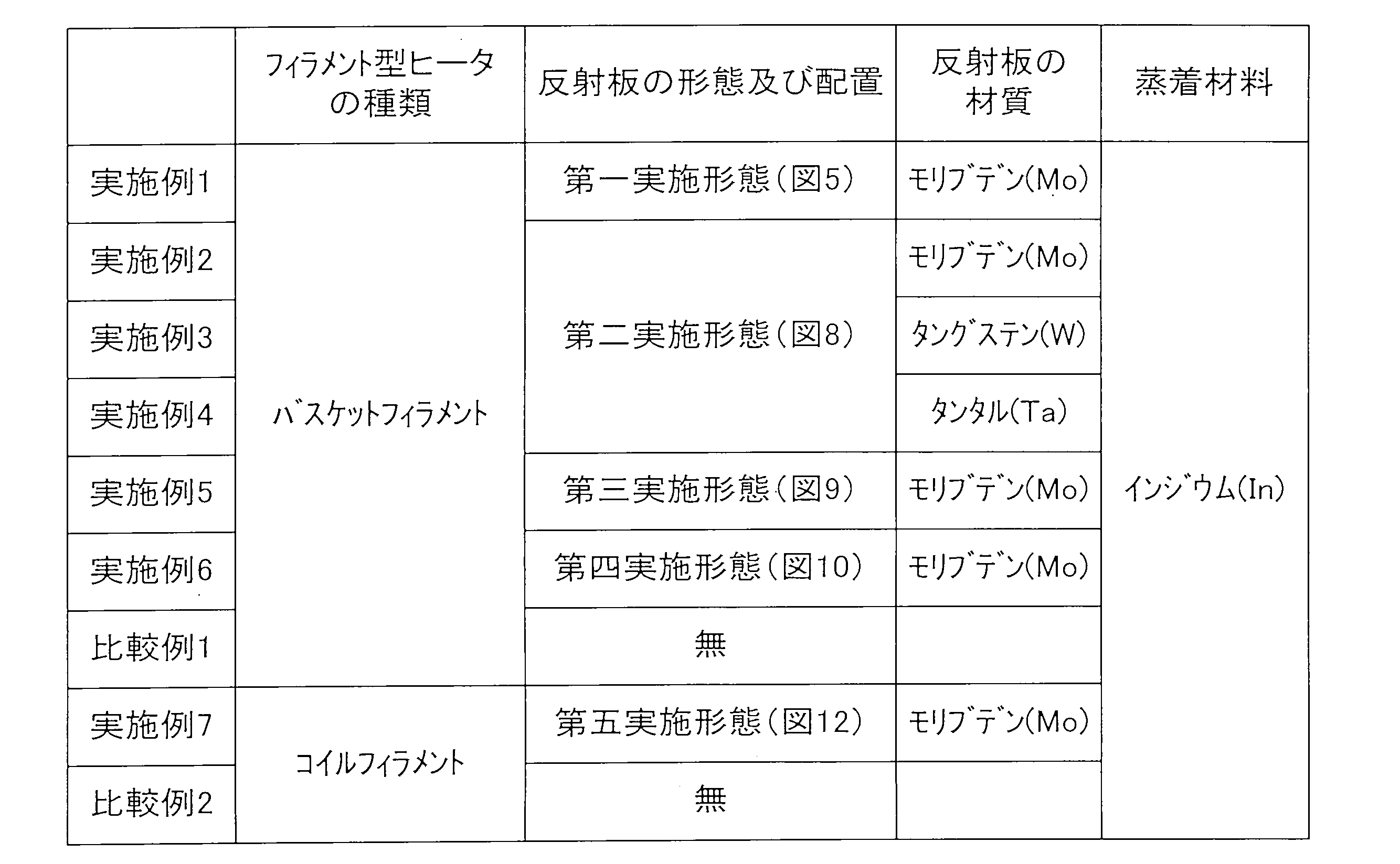
また、各例にて成膜されたインジウム薄膜の膜厚を、水晶振動式膜厚計(インフィコン株式会社製:XTCS-1000)を用いて測定した。そして、各例における膜厚比を算出した。ここで、膜厚比とは、比較例において測定した膜厚を100とした場合における実施例において測定した膜厚の比である。また、実施例1~6については、比較例1の膜厚を100とした場合における膜厚比を算出し、実施例7においては、比較例2の膜厚を100とした場合における膜厚比を算出した。また、各例において、成膜中の基材表面(蒸着面)の温度を、接触式温度計(理化工業株式会社製:DP-500)を用いて測定した。表2に、各例にて算出した膜厚比及び基材表面温度の測定結果を示す。

表2からわかるように、いずれの実施例においても、比較例に対して1.5倍以上の厚さの薄膜が成膜されていることがわかる。このことから、本実施形態において、反射板を設けたことによって、蒸着材料の収率を向上できることがわかる。
また、本実施形態によれば、反射板がフィラメント型ヒータの熱で加熱されているが、もし反射板の熱が基材に伝わって基材が過剰に加熱されると、基材が熱劣化を起こす虞がある。特に、反射板が基材に近い位置に配設されている場合、反射板の熱で基材が熱劣化を起こす可能性が高い。例えば特許文献1及び特許文献2のように、蒸着材料から基材に至る空間を取り囲むように加熱された反射板が配置されている場合、すなわち、基材から見て蒸着材料の前方に加熱された反射板が配設されている場合には、反射板の熱により基材が加熱して熱変形を起こす虞がある。この点に関し、本実施形態においては、加熱された反射板は、蒸着材料の後方、すなわち蒸着材料から見て基材から遠ざかる位置に配設されている。言い換えれば、本実施形態においては、加熱された反射板は、基材から見て蒸着材料の前方には配設されていない。このため、反射板の熱が基材に伝達され難い。それ故に、表2に示すように、各例において、成膜中の基材表面温度は、50℃~60℃程度であり、一般的な樹脂基材の熱変形温度以下である。このため、反射板の熱による基材の熱劣化を効果的に防止することができる。
以上、本発明の様々な実施形態及び実施例について説明したが、本発明は上記実施形態及び実施例に限定されるべきものではない。例えば、上記各実施例においては、フィラメント型ヒータとしてバスケットフィラメント型ヒータ及びコイルフィラメント型ヒータを用いたが、線状の発熱体により構成され且つ線状の発熱体が折り曲げられることによって形成された収容部を有するフィラメント型ヒータであれば、本発明に適用することができる。また、上記各実施例においては、フィラメント型ヒータの材質がタングステンであるが、ヒータとして利用できるその他の材質によりフィラメント型ヒータを構成することもできる。このように、本発明は、その趣旨を逸脱しない限りにおいて、変形可能である。
Claims (5)
- 基材を保持する保持部と、
通電することにより発熱する線状の発熱体により構成され、前記線状の発熱体を折り曲げることにより蒸着材料を収容することができるように形成された収容部を有し、前記保持部に保持されている前記基材に対して水平方向に所定の距離だけ離間して前記収容部が位置するように配設されたフィラメント型ヒータと、
前記保持部に保持されている前記基材から見て、前記収容部に収容されている前記蒸着材料の後方に配設されるとともに、前記フィラメント型ヒータから熱が伝達されるように構成された反射板と、
を備える、蒸着装置。 - 請求項1に記載の蒸着装置において、
前記反射板が前記収容部内に配設されている、蒸着装置。 - 請求項2に記載の蒸着装置において、
前記収容部は、前記線状の発熱体を螺旋状に巻回することにより、その外形形状が下に凸の円錐形状となるように形成され、
前記反射板は、半円錐形状に形成されていて、下に凸となるように前記収容部内に配設されている、蒸着装置。 - 請求項1に記載の蒸着装置において、
前記反射板は、前記保持部に保持されている基材からみて前記収容部の後方に配設された背面板を有する、蒸着装置。 - 請求項4に記載の蒸着装置において、
前記反射板は、前記収容部の上方に配設された上板及び前記収容部の下方に配設された下板を有する、蒸着装置。
Priority Applications (2)
| Application Number | Priority Date | Filing Date | Title |
|---|---|---|---|
| US15/735,698 US10787734B2 (en) | 2015-07-15 | 2016-06-21 | Vapor deposition device |
| CN201680041485.6A CN107849685B (zh) | 2015-07-15 | 2016-06-21 | 蒸镀装置 |
Applications Claiming Priority (2)
| Application Number | Priority Date | Filing Date | Title |
|---|---|---|---|
| JP2015141357A JP6488928B2 (ja) | 2015-07-15 | 2015-07-15 | 蒸着装置 |
| JP2015-141357 | 2015-07-15 |
Publications (1)
| Publication Number | Publication Date |
|---|---|
| WO2017010243A1 true WO2017010243A1 (ja) | 2017-01-19 |
Family
ID=57756965
Family Applications (1)
| Application Number | Title | Priority Date | Filing Date |
|---|---|---|---|
| PCT/JP2016/068407 Ceased WO2017010243A1 (ja) | 2015-07-15 | 2016-06-21 | 蒸着装置 |
Country Status (4)
| Country | Link |
|---|---|
| US (1) | US10787734B2 (ja) |
| JP (1) | JP6488928B2 (ja) |
| CN (1) | CN107849685B (ja) |
| WO (1) | WO2017010243A1 (ja) |
Cited By (1)
| Publication number | Priority date | Publication date | Assignee | Title |
|---|---|---|---|---|
| JP2020193368A (ja) * | 2019-05-28 | 2020-12-03 | キヤノントッキ株式会社 | 加熱装置、蒸発源装置、成膜装置、成膜方法および電子デバイスの製造方法 |
Families Citing this family (1)
| Publication number | Priority date | Publication date | Assignee | Title |
|---|---|---|---|---|
| CN118996341B (zh) * | 2024-10-25 | 2025-02-14 | 安徽华远装备科技有限公司 | 一种镀膜蒸汽立式布气装置及其使用方法 |
Citations (3)
| Publication number | Priority date | Publication date | Assignee | Title |
|---|---|---|---|---|
| JPS60113753U (ja) * | 1983-12-29 | 1985-08-01 | タイガー魔法瓶株式会社 | 液体容器のコツプ |
| JPS6115963A (ja) * | 1984-07-02 | 1986-01-24 | Hitachi Ltd | ブラウン管メタルバツク蒸着用ヒ−タコイル |
| JP2004100002A (ja) * | 2002-09-11 | 2004-04-02 | Ulvac Japan Ltd | 蒸発源及びこれを用いた薄膜形成装置 |
Family Cites Families (17)
| Publication number | Priority date | Publication date | Assignee | Title |
|---|---|---|---|---|
| US3538305A (en) * | 1969-05-16 | 1970-11-03 | Us Navy | Alloy deterring shunt for conical tungsten evaporation sources |
| JPS51107285A (ja) | 1975-03-18 | 1976-09-22 | Mitsubishi Electric Corp | Shinkujochakusochi |
| US4054500A (en) * | 1975-04-28 | 1977-10-18 | Gte Sylvania Incorporated | Method of making refractory metal-ceramic crucible |
| US4390571A (en) * | 1981-06-30 | 1983-06-28 | International Business Machines Corporation | Boatless point source evaporation method |
| JPS6025749U (ja) * | 1983-07-22 | 1985-02-21 | 日本電気株式会社 | 蒸着ヒ−タ |
| US4812352A (en) * | 1986-08-25 | 1989-03-14 | Minnesota Mining And Manufacturing Company | Article having surface layer of uniformly oriented, crystalline, organic microstructures |
| JPH049463A (ja) * | 1990-04-26 | 1992-01-14 | Oki Electric Ind Co Ltd | 薄膜の製造方法 |
| JPH04228561A (ja) * | 1990-12-27 | 1992-08-18 | Matsushita Electric Ind Co Ltd | 真空蒸発源および薄膜形成装置 |
| JP3242427B2 (ja) | 1991-09-11 | 2001-12-25 | コニカ株式会社 | 蒸着装置 |
| JPH0853763A (ja) | 1994-06-06 | 1996-02-27 | Matsushita Electric Ind Co Ltd | 薄膜の製造方法 |
| JP3730402B2 (ja) | 1998-03-26 | 2006-01-05 | 日本電子株式会社 | 蒸着装置および前記蒸着装置を備えた試料分析装置 |
| ATE497028T1 (de) * | 2000-06-22 | 2011-02-15 | Panasonic Elec Works Co Ltd | Vorrichtung und verfahren zum vakuum-ausdampfen |
| JP2003002778A (ja) * | 2001-06-26 | 2003-01-08 | International Manufacturing & Engineering Services Co Ltd | 薄膜堆積用分子線セル |
| US20030026601A1 (en) * | 2001-07-31 | 2003-02-06 | The Arizona Board Of Regents On Behalf Of The University Of Arizona | Vapor deposition and in-situ purification of organic molecules |
| JP2008138261A (ja) | 2006-12-04 | 2008-06-19 | Tokki Corp | 真空蒸着装置及び方法 |
| US8691064B2 (en) * | 2007-07-09 | 2014-04-08 | Raytheon Canada Limited | Sputter-enhanced evaporative deposition apparatus and method |
| JP5400749B2 (ja) | 2010-12-01 | 2014-01-29 | 株式会社日立ハイテクノロジーズ | 蒸着装置 |
-
2015
- 2015-07-15 JP JP2015141357A patent/JP6488928B2/ja not_active Expired - Fee Related
-
2016
- 2016-06-21 CN CN201680041485.6A patent/CN107849685B/zh active Active
- 2016-06-21 US US15/735,698 patent/US10787734B2/en active Active
- 2016-06-21 WO PCT/JP2016/068407 patent/WO2017010243A1/ja not_active Ceased
Patent Citations (3)
| Publication number | Priority date | Publication date | Assignee | Title |
|---|---|---|---|---|
| JPS60113753U (ja) * | 1983-12-29 | 1985-08-01 | タイガー魔法瓶株式会社 | 液体容器のコツプ |
| JPS6115963A (ja) * | 1984-07-02 | 1986-01-24 | Hitachi Ltd | ブラウン管メタルバツク蒸着用ヒ−タコイル |
| JP2004100002A (ja) * | 2002-09-11 | 2004-04-02 | Ulvac Japan Ltd | 蒸発源及びこれを用いた薄膜形成装置 |
Cited By (2)
| Publication number | Priority date | Publication date | Assignee | Title |
|---|---|---|---|---|
| JP2020193368A (ja) * | 2019-05-28 | 2020-12-03 | キヤノントッキ株式会社 | 加熱装置、蒸発源装置、成膜装置、成膜方法および電子デバイスの製造方法 |
| JP7241604B2 (ja) | 2019-05-28 | 2023-03-17 | キヤノントッキ株式会社 | 加熱装置、蒸発源装置、成膜装置、成膜方法および電子デバイスの製造方法 |
Also Published As
| Publication number | Publication date |
|---|---|
| US10787734B2 (en) | 2020-09-29 |
| JP2017020099A (ja) | 2017-01-26 |
| US20190264319A1 (en) | 2019-08-29 |
| JP6488928B2 (ja) | 2019-03-27 |
| CN107849685B (zh) | 2020-08-11 |
| CN107849685A (zh) | 2018-03-27 |
Similar Documents
| Publication | Publication Date | Title |
|---|---|---|
| JP6488928B2 (ja) | 蒸着装置 | |
| JP5726546B2 (ja) | チャンバ装置 | |
| CN106133844A (zh) | 熔盐反应堆中的化学优化 | |
| JP6021422B2 (ja) | チャンバ装置 | |
| CN104540618A (zh) | 舟皿和线圈设计 | |
| JP2013179029A (ja) | ターゲット供給装置、および、ターゲット供給方法 | |
| JP6310244B2 (ja) | 放射性物質収納用キャスクの製造方法 | |
| US2472930A (en) | Electrical heating unit | |
| JP6397834B2 (ja) | るつぼ材料 | |
| ES2877451T3 (es) | Tubo colector de calor solar y procedimiento de producción del mismo | |
| Beck et al. | Hot corrosion behavior of Mo–Si–Ti alloys | |
| US8709158B2 (en) | Thermal management of film deposition processes | |
| EP3355751B1 (fr) | Récipient de cuisson comportant un dispositif de récupération d'énergie | |
| JP2011162867A (ja) | 真空蒸発装置 | |
| JP5657535B2 (ja) | 汚染物捕獲体を含む極紫外線放射生成装置 | |
| KR102692383B1 (ko) | 히터 서포트 및 히터 장치 | |
| JP5937731B2 (ja) | スパッタリングターゲット | |
| US20190041097A1 (en) | Solar heat collector tube | |
| JP2023022818A5 (ja) | ||
| WO2018042565A1 (ja) | ドロップレット回収装置 | |
| Brenčič | Correspondence between Vasily Vasilyevich Nikitin and Vladimir Ivanovich Vernadsky | |
| JP6047292B2 (ja) | 水素発生装置 | |
| RU2374705C2 (ru) | Способ изготовления твэла дисперсионного типа | |
| US11231208B2 (en) | Solar heat collector tube | |
| JP6059886B2 (ja) | 水素発生装置 |
Legal Events
| Date | Code | Title | Description |
|---|---|---|---|
| 121 | Ep: the epo has been informed by wipo that ep was designated in this application |
Ref document number: 16824223 Country of ref document: EP Kind code of ref document: A1 |
|
| NENP | Non-entry into the national phase |
Ref country code: DE |
|
| 122 | Ep: pct application non-entry in european phase |
Ref document number: 16824223 Country of ref document: EP Kind code of ref document: A1 |