WO2017010218A1 - 偏光性成形体 - Google Patents
偏光性成形体 Download PDFInfo
- Publication number
- WO2017010218A1 WO2017010218A1 PCT/JP2016/067876 JP2016067876W WO2017010218A1 WO 2017010218 A1 WO2017010218 A1 WO 2017010218A1 JP 2016067876 W JP2016067876 W JP 2016067876W WO 2017010218 A1 WO2017010218 A1 WO 2017010218A1
- Authority
- WO
- WIPO (PCT)
- Prior art keywords
- protective layer
- polarizing
- film
- transparent
- sheet
- Prior art date
- Legal status (The legal status is an assumption and is not a legal conclusion. Google has not performed a legal analysis and makes no representation as to the accuracy of the status listed.)
- Ceased
Links
Images

Classifications
-
- B—PERFORMING OPERATIONS; TRANSPORTING
- B29—WORKING OF PLASTICS; WORKING OF SUBSTANCES IN A PLASTIC STATE IN GENERAL
- B29D—PRODUCING PARTICULAR ARTICLES FROM PLASTICS OR FROM SUBSTANCES IN A PLASTIC STATE
- B29D11/00—Producing optical elements, e.g. lenses or prisms
- B29D11/00634—Production of filters
- B29D11/00644—Production of filters polarizing
-
- B—PERFORMING OPERATIONS; TRANSPORTING
- B29—WORKING OF PLASTICS; WORKING OF SUBSTANCES IN A PLASTIC STATE IN GENERAL
- B29C—SHAPING OR JOINING OF PLASTICS; SHAPING OF MATERIAL IN A PLASTIC STATE, NOT OTHERWISE PROVIDED FOR; AFTER-TREATMENT OF THE SHAPED PRODUCTS, e.g. REPAIRING
- B29C45/00—Injection moulding, i.e. forcing the required volume of moulding material through a nozzle into a closed mould; Apparatus therefor
- B29C45/0001—Injection moulding, i.e. forcing the required volume of moulding material through a nozzle into a closed mould; Apparatus therefor characterised by the choice of material
-
- B—PERFORMING OPERATIONS; TRANSPORTING
- B29—WORKING OF PLASTICS; WORKING OF SUBSTANCES IN A PLASTIC STATE IN GENERAL
- B29C—SHAPING OR JOINING OF PLASTICS; SHAPING OF MATERIAL IN A PLASTIC STATE, NOT OTHERWISE PROVIDED FOR; AFTER-TREATMENT OF THE SHAPED PRODUCTS, e.g. REPAIRING
- B29C45/00—Injection moulding, i.e. forcing the required volume of moulding material through a nozzle into a closed mould; Apparatus therefor
- B29C45/17—Component parts, details or accessories; Auxiliary operations
- B29C45/72—Heating or cooling
- B29C45/73—Heating or cooling of the mould
-
- B—PERFORMING OPERATIONS; TRANSPORTING
- B29—WORKING OF PLASTICS; WORKING OF SUBSTANCES IN A PLASTIC STATE IN GENERAL
- B29C—SHAPING OR JOINING OF PLASTICS; SHAPING OF MATERIAL IN A PLASTIC STATE, NOT OTHERWISE PROVIDED FOR; AFTER-TREATMENT OF THE SHAPED PRODUCTS, e.g. REPAIRING
- B29C53/00—Shaping by bending, folding, twisting, straightening or flattening; Apparatus therefor
- B29C53/02—Bending or folding
- B29C53/04—Bending or folding of plates or sheets
-
- B—PERFORMING OPERATIONS; TRANSPORTING
- B29—WORKING OF PLASTICS; WORKING OF SUBSTANCES IN A PLASTIC STATE IN GENERAL
- B29C—SHAPING OR JOINING OF PLASTICS; SHAPING OF MATERIAL IN A PLASTIC STATE, NOT OTHERWISE PROVIDED FOR; AFTER-TREATMENT OF THE SHAPED PRODUCTS, e.g. REPAIRING
- B29C65/00—Joining or sealing of preformed parts, e.g. welding of plastics materials; Apparatus therefor
- B29C65/02—Joining or sealing of preformed parts, e.g. welding of plastics materials; Apparatus therefor by heating, with or without pressure
-
- B—PERFORMING OPERATIONS; TRANSPORTING
- B29—WORKING OF PLASTICS; WORKING OF SUBSTANCES IN A PLASTIC STATE IN GENERAL
- B29D—PRODUCING PARTICULAR ARTICLES FROM PLASTICS OR FROM SUBSTANCES IN A PLASTIC STATE
- B29D11/00—Producing optical elements, e.g. lenses or prisms
- B29D11/0073—Optical laminates
-
- G—PHYSICS
- G02—OPTICS
- G02B—OPTICAL ELEMENTS, SYSTEMS OR APPARATUS
- G02B1/00—Optical elements characterised by the material of which they are made; Optical coatings for optical elements
- G02B1/04—Optical elements characterised by the material of which they are made; Optical coatings for optical elements made of organic materials, e.g. plastics
- G02B1/041—Lenses
-
- G—PHYSICS
- G02—OPTICS
- G02B—OPTICAL ELEMENTS, SYSTEMS OR APPARATUS
- G02B1/00—Optical elements characterised by the material of which they are made; Optical coatings for optical elements
- G02B1/10—Optical coatings produced by application to, or surface treatment of, optical elements
- G02B1/14—Protective coatings, e.g. hard coatings
-
- G—PHYSICS
- G02—OPTICS
- G02B—OPTICAL ELEMENTS, SYSTEMS OR APPARATUS
- G02B5/00—Optical elements other than lenses
- G02B5/30—Polarising elements
-
- G—PHYSICS
- G02—OPTICS
- G02B—OPTICAL ELEMENTS, SYSTEMS OR APPARATUS
- G02B5/00—Optical elements other than lenses
- G02B5/30—Polarising elements
- G02B5/3025—Polarisers, i.e. arrangements capable of producing a definite output polarisation state from an unpolarised input state
- G02B5/3033—Polarisers, i.e. arrangements capable of producing a definite output polarisation state from an unpolarised input state in the form of a thin sheet or foil, e.g. Polaroid
-
- G—PHYSICS
- G02—OPTICS
- G02C—SPECTACLES; SUNGLASSES OR GOGGLES INSOFAR AS THEY HAVE THE SAME FEATURES AS SPECTACLES; CONTACT LENSES
- G02C7/00—Optical parts
- G02C7/12—Polarisers
-
- B—PERFORMING OPERATIONS; TRANSPORTING
- B29—WORKING OF PLASTICS; WORKING OF SUBSTANCES IN A PLASTIC STATE IN GENERAL
- B29K—INDEXING SCHEME ASSOCIATED WITH SUBCLASSES B29B, B29C OR B29D, RELATING TO MOULDING MATERIALS OR TO MATERIALS FOR MOULDS, REINFORCEMENTS, FILLERS OR PREFORMED PARTS, e.g. INSERTS
- B29K2077/00—Use of PA, i.e. polyamides, e.g. polyesteramides or derivatives thereof, as moulding material
-
- B—PERFORMING OPERATIONS; TRANSPORTING
- B29—WORKING OF PLASTICS; WORKING OF SUBSTANCES IN A PLASTIC STATE IN GENERAL
- B29K—INDEXING SCHEME ASSOCIATED WITH SUBCLASSES B29B, B29C OR B29D, RELATING TO MOULDING MATERIALS OR TO MATERIALS FOR MOULDS, REINFORCEMENTS, FILLERS OR PREFORMED PARTS, e.g. INSERTS
- B29K2601/00—Use of cellulose, modified cellulose or cellulose derivatives, e.g. viscose, for preformed parts, e.g. for inserts
- B29K2601/08—Cellulose derivatives
-
- B—PERFORMING OPERATIONS; TRANSPORTING
- B29—WORKING OF PLASTICS; WORKING OF SUBSTANCES IN A PLASTIC STATE IN GENERAL
- B29K—INDEXING SCHEME ASSOCIATED WITH SUBCLASSES B29B, B29C OR B29D, RELATING TO MOULDING MATERIALS OR TO MATERIALS FOR MOULDS, REINFORCEMENTS, FILLERS OR PREFORMED PARTS, e.g. INSERTS
- B29K2677/00—Use of PA, i.e. polyamides, e.g. polyesteramides or derivatives thereof, for preformed parts, e.g. for inserts
-
- G—PHYSICS
- G02—OPTICS
- G02C—SPECTACLES; SUNGLASSES OR GOGGLES INSOFAR AS THEY HAVE THE SAME FEATURES AS SPECTACLES; CONTACT LENSES
- G02C2202/00—Generic optical aspects applicable to one or more of the subgroups of G02C7/00
- G02C2202/16—Laminated or compound lenses
Definitions
- the present invention relates to a polarizing molded body used for spectacles, in which an injection molding portion of a thermoplastic resin is thermally bonded to a concave surface side of a polarizing sheet having a curvature.
- the invention relates to a polarizing molded article that is less likely to cause variations in polarization performance in the polarizing sheet, has excellent polarization characteristics, is light and has a clear field of view, and is suitable as a material for goggles and sunglasses.
- ⁇ Abbe number ( ⁇ )> ⁇ (nd-1) / (nF-nC)
- Abbe number ( ⁇ ) is the reciprocal of dispersion
- nd is the refractive index for light at 587.6 nm
- nF is the refractive index for light at 486.1 nm
- nC is the refractive index for light at 656.3 nm.
- Retardation value (Re)> Re (nm) defined by ⁇ n ⁇ d, a value at a wavelength of 632.8 nm. Since Re is measured in the vertical and horizontal directions, in the present invention, the arithmetic average of the vertical and horizontal directions is used.
- ⁇ n means the amount of birefringence
- ⁇ n ne ⁇ no (ne is the refractive index for ordinary light, and no is the refractive index for extraordinary light)
- d is defined by the film thickness.
- Patent Documents 1 to 3 can be cited as prior art documents related to the above-described polarizing molded article.
- Patent Document 1 paragraphs 0002 to 0008.
- the present invention relates to a technique for providing a polarizing base material incorporating a polarizer and having a high impact strength, for example, a lens base material used for impact-resistant goggles, sunglasses, and prescription sunglasses.
- polarizing glass lenses in which both surfaces of a polarizer sheet are covered with glass, and polarizing plastic lenses such as a polarizing CR-39 lens cast by inserting a polarizer sheet into a mold.
- the polarizing glass lens sheet in which both surfaces of the above-described polarizer sheet are covered with glass has a tendency to break due to being a glass substrate, and lack of workability due to the substrate being difficult to deform.
- a polarizing plastic lens cast by inserting a polarizer sheet into a mold requires technology to incorporate the polarizer sheet into the mold, and the polarizer sheet shrinks due to long-term heat received during casting.
- the polarization performance deteriorated due to thermal decomposition.
- an optical composite molded article obtained by insert injection molding so that a polycarbonate resin layer is thermally bonded to a polycarbonate sheet as an outermost layer of a polarizing plate includes a polarizing plate and a resin layer. Since the heat at the time of molding is transmitted straight to the polarizing plate, the polarization performance is degraded due to the shrinkage and thermal decomposition of the polarizer sheet, as in the case of cast molding.
- the technical means of the present invention for solving the above technical problem is a polarizing molded article having a laminated structure including a polarizing plate in which a polarizer sheet layer is sandwiched between two protective sheet layers, the protective sheet layer having one layer. And the polyurethane sheet layer or the polyamide sheet layer are bonded with an adhesive or a pressure-sensitive adhesive, and the polyurethane sheet layer or the polyamide sheet layer and the thermoforming resin layer are thermally bonded.
- a polarizing sheet (polarizing sheet) described in Patent Document 2 [paragraphs 0056 to 0070] etc.
- Protective film is made of a polyamide resin such as a specific alicyclic polyamide resin.
- a polarizing molded product described in the same document [paragraphs 0072 to 0077]“ on the concave surface side of the polarizing sheet (polarizing sheet), the same or the same resin as the protective film layer It is conceivable to use a technique of producing a polarizing laminate (polarizing molded body) by insert injection molding using a polyamide-based resin such as alicyclic polyamide.
- the polarizing sheet according to the technology has a high Abbe number compared to the polycarbonate resin, so that the generation of iridescent color unevenness can be efficiently prevented.
- orientation tilting treatment
- Re retardation value
- the Re of the protective film is set to “300 nm” or more because the Re exceeds the upper limit Re (400 nm) ([0012], [0046]) where white increases (whitening) occurs due to bending. This is because white spots do not occur.
- the protective film made of polyamide resin usually has a high magnification (1.06 to 3.0 times; “1.0” in Example 3 is erroneous) as in the examples of the same document [Table 1]. )), It is easy to heat shrink during injection molding.
- the incident light that reaches the polarizer layer from the first protective layer is slightly polarized as the amount of birefringence increases.
- the polarization performance (including the degree of polarization) of the polarizing sheet is likely to vary (see Patent Document 1 [paragraph 0028]).
- Patent Document 3 describes and proposes various molds for insert injection molding of a polarizing molded body (see [paragraphs 0002 to 0006], [paragraphs 0008 to 0009] and [FIG. 1]).
- JP 2002-189199 A International Publication WO2006 / 040954 Japanese Patent Laid-Open No. 11-245259
- the problem of the present invention is that the polarizing sheet is less likely to cause color unevenness and white spots, and is less likely to cause variations in the degree of polarization of the polarizing sheet due to thermal contraction of the protective layer (protective film).
- An object of the present invention is to provide a product with good productivity.
- a polarizing molded body used for spectacles An injection-molded portion made of a transparent molding material is thermally bonded to the concave surface side of the polarizing sheet having a predetermined radius of curvature, and the polarizing sheet has a first protective layer and a second protective layer in which the polarizer layer is on the convex surface side and the concave surface side, respectively. Sandwiched between protective layers, Both the first protective layer and the second protective layer are formed of a transparent film by a casting method in which retardation (Re) ⁇ 50 nm, and the transparent films of the first protective layer and the second protective layer are acylcellulose-based and polyamide, respectively. Made of plastic film material, The second protective layer and the injection-molded part are directly fused.
- the polarizing molded body according to the present invention is less likely to cause color unevenness and white spots as will be described in Examples below.
- first and second protective layers are made of transparent films having extremely small or non-oriented retardation values (Re) (that is, relatively low birefringence amount), so that heat during injection molding can be obtained. Thermal shrinkage in one direction due to the influence of the protective film is less likely to occur, and the defective product generation rate is reduced.
- Re retardation value
- FIG. 1A is a cross-sectional view showing the inversion step of the polarizing sheet in the present invention
- FIG. 1B is a cross-sectional view of the polarizing molded body in the present invention.
- the polarizing molded body 10 is used for eyeglasses, and is formed by thermally bonding an injection molding portion 15 made of a transparent molding material to the concave surface side of a polarizing sheet 11 having a predetermined radius of curvature.
- a polarizer layer (polarizer film) 13 is sandwiched between first and second protective layers (protective films) 17 and 19 on the convex surface side and the concave surface side, respectively.
- the polarizing molded body 10 of the present invention in Patent Document 1, replaces the TAC-based transparent film forming the second protective layer of the polarizing sheet with a polyamide-based film material, and includes a polarizing sheet and an injection-molded portion.
- the polyamide sheet layer interposed therebetween is discarded, and the injection molding part 15 made of a transparent molding material is directly fused to the second protective layer 19 on the concave surface side.
- document refers to “patent document” unless otherwise specified.
- the polarizer layer 13 is sandwiched between first and second protective layers 17 and 19 that are on the convex surface side and the concave surface side, respectively.
- the polarizer layer 13 those described in Document 1 (paragraphs 0020 to 0022) can be used. That is, it is formed with a polarizer film having a degree of polarization of 80% or more, desirably 90% or more, and more desirably 99% or more by appropriately doping using a uniaxially stretched sheet such as polyvinyl alcohol (PVA). is there.
- PVA polyvinyl alcohol
- the first and second protective layers 17 and 19 are transparent films made of acyl cellulose and polyamide film materials each having a retardation value (Re) ⁇ 50 nm, preferably Re ⁇ 10 nm, and more preferably Re ⁇ 5 nm. Is formed.
- Re ⁇ 50 nm is the lower limit Re “150 nm” at which Re does not cause white spots in the polarizing sheet (protective layer) even if Re increases by bending (Reference 2 [paragraph 0012, This is because it is difficult to reach (0046)).
- Re after bending is 20 times, but the protective layer is an unstretched extruded film (having orientation). It is not discussed the same as the cast of the present invention.
- the polarizing sheet 11 has Re ⁇ 50 nm, more preferably Re ⁇ 10 nm after bending.
- Re of the first protective layer 17 is preferably formed of a transparent film of Re ⁇ 10 nm and smaller than Re of the second protective layer 19. If the Re of the first protective layer 17 is large, the incident light that reaches the polarizer layer 13 from the first protective layer 17 may be slightly polarized, resulting in variations in the polarization performance of the polarizer layer 13, and the surface side. Therefore, when white spots occur, it is easily noticeable.
- a transparent film by a casting method is usually used without stretching.
- the film material of the transparent film forming the first and second protective layers 17 and 19 preferably has an Abbe number ( ⁇ ) ⁇ 44, and further ⁇ ⁇ 50 (Document 2 [paragraph 0039]). The most desirable range).
- the film material (acylcellulose type) of the first protective layer 17 preferably exhibits a higher Abbe number than the film material (polyamide type) of the second protective layer 19 assuming that ⁇ ⁇ 54 (reference 2 [paragraph] [0039] The most desirable range).
- the film material of the first protective layer 17 is not particularly limited as long as it is an acylcellulose type that can satisfy the above requirements. In particular, from the viewpoint of suppressing color unevenness, it is easy to obtain a film with ⁇ ⁇ 54, and polarized light. Triacetyl cellulose (TAC), which is widely used as a sheet, is desirable (Reference 2 [paragraph 0039]).
- the second protective layer 17 is directly fused to the injection molding part 15.
- the transparent molding material of the injection molding part 15 it is desirable to use the same polyamide system as the film material of the second protective layer 19.
- a low-density one can be selected.
- the polarizing sheet 11 normally has a first protective layer 17 made of an acylcellulose-based film material inside, and a second protective layer 19 made of a transparent polyamide-based film material. Bending into a spherical shape on the outside (hot press molding), and then reversing and using. After bending, annealing is usually performed to remove internal stress from the standpoint of dimensional stability, etc. (temperature rising immediately below the heat distortion temperature and then slow cooling). The transparent film made of the polyamide-based film material as the two protective layers 19 is thermally shrunk. This is consistent with the description in Document 1 (18th column, lines 28 to 35) in which the polarizing composite sheet is used after being bent.
- amorphous to microcrystalline nylon As the polyamide-based film material of the second protective layer 17, those generally referred to as amorphous to microcrystalline nylon can be used, for example, those described in Document 2 (paragraph 0026) are used. Is possible.
- the alicyclic polyamide (alicyclic PA) represented by the formula (1) is excellent in transparency, chemical resistance and the like, it can be suitably used.
- a light transmittance of 80% or more, desirably 85% or more, and more preferably 90% or more is desirable.
- X represents a direct bond, an alkylene group or an alkenyl group
- R1 and R2 represent the same or different alkyl groups
- m and n are integers of 1 to 4
- p and q are integers of 1 or more. Showing).
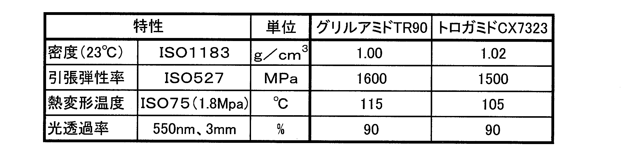
- density (ISO1183) 1.03g / cm 3 or less, preferably 1.02 g / cm 3 or less, more preferably, to 1.01 g / cm 3 or less.
- the tensile modulus (ISO 527) is 1400 to 2000 mPa, preferably 1500 to 1800 mPa. If the rigidity is too high, it is difficult to obtain impact resistance, and if it is low, it is difficult to ensure the strength as spectacles.
- the glass transition point (ISO11367) is 140 to 200 ° C, preferably 130 to 160 ° C.
- transparent polyamides exhibiting these properties include, among others, “Grilamid” (registered trademark) from Ems and “Torogamid” (registered trademark) from Daicel Evonik. Can be selected.
- Each of these films is laminated and formed into a polarizing sheet having a three-layer structure using an adhesive or a pressure-sensitive adhesive by a conventional method (for example, see Document 1 [paragraphs 0034 to 0037]).
- first protective layer for TAC
- polarizer layer for PVA
- PVA polarizer layer
- Two protective layers alicyclic polyamide: 80 to 120 ⁇ m (preferably 90 to 110 ⁇ m).
- Each of these layers is desirably as thin as possible from the viewpoint of weight reduction and Re within a range that does not impair each function and film formability.
- the above polarizing sheets are manufactured and sold by companies such as Sumitomo Bakelite, Mitsubishi Gas Chemical Co., Polatechno Co., Ltd., etc. If so, it can be easily obtained.
- the polarizing sheet prepared above is thermoformed (bent) into a predetermined curvature by a conventional method.
- the curvature is usually appropriately selected from the range of 4C to 8C.
- the curvature was calculated with a refractive index of 1.534 for convenience. Therefore, 4C is 133.62 mm, 6C is 89.08 mm, and 8C is 66.81 mm.
- the Re of the polarizing sheet (three layers) after the bending process should satisfy Re ⁇ 50 from the viewpoint of visibility and the like.
- the polarizing sheet bent into a spherical shape is inverted as described above, set in a mold, and an injection molded part is formed by insert injection molding or the like using a transparent molding material. Since injection molding can be released in a very short time (within 2 minutes after injection), the polarizing sheet is hardly affected by heat.
- the transparent molding material is not particularly limited as long as it can be heat-sealed with the second protective layer made of a polyamide-based film material.
- the transparent molding material is a low-density polyamide-based transparent molding material that is the same or similar to the film material. It is desirable to use those having good fusion properties.
- the polyamide-based transparent molding material shown is used.
- the resin material injection temperature of the transparent molding material varies depending on the polyamide grade, but is 230 to 270 ° C. in the case of the alicyclic polyamide.
- the mold temperature is 60 to 100 ° C.
- the injection mold can be appropriately selected from conventional molds (typically 4 to 8 pieces) as described in Document 3.
- the polarizing molded body in the present invention is used for spectacles, usually, the front side (object side) and further, the back side (eyeball side) are coated with a hard coat film through a primer film as before.
- the hard coat film is covered with a functional surface processed film including a vapor deposition film.
- thermoplastic elastomer As the material for forming the primer film, a thermoplastic elastomer can usually be used from the viewpoint of impact resistance, and as the hard coat film, a silicone system having excellent scratch resistance can be used.
- Examples of the functional surface processed film include an antireflection film or a mirror film formed by a multilayer vapor deposition film. It is desirable that the surface of these antireflection film and mirror film is further antifogged with a water repellent film or the like.
- Molded plastic material Alicyclic PA (same material as the second protective layer), injection temperature: 270 ° C., mold temperature: 100 ° C.
- Reference example: Molded plastic material: PC ( ⁇ 30), injection temperature: 310 ° C., mold temperature: 100 ° C., ⁇ Test method>
- Retardation value (Re) (8C) ...
- the polarizer layer is usually uniaxially stretched at a high magnification as described above (see the above-mentioned document 2, paragraph 0058). For this reason, it is presumed that Re of the polarizing sheet sandwiched between the non-stretched protective layers of the observed examples is mainly caused by Re of the polarizer layer.
- the longitudinal Re of the polarizing sheet (three layers) after bending is 5.8 nm, it is unlikely that the Re of the polarizing sheet after bending exceeds 10 nm to 5 nm as well as 50 nm.
- the protective layer also does not exceed 10 nm to 5 nm.
- Example: ⁇ Reference example: ⁇
- the polarizing sheet of the example (after bending) was confirmed to have no white spots in the protective film.
- Example: A Reference example: ⁇
- the polarizing molded body of the example was observed obliquely from the front, it was confirmed that no color unevenness occurred.
Landscapes
- Physics & Mathematics (AREA)
- Engineering & Computer Science (AREA)
- General Physics & Mathematics (AREA)
- Optics & Photonics (AREA)
- Health & Medical Sciences (AREA)
- Ophthalmology & Optometry (AREA)
- Mechanical Engineering (AREA)
- Manufacturing & Machinery (AREA)
- General Health & Medical Sciences (AREA)
- Polarising Elements (AREA)
- Manufacture Of Macromolecular Shaped Articles (AREA)
- Injection Moulding Of Plastics Or The Like (AREA)
Abstract
Description
ν=(nd-1)/(nF―nC)
アッベ数(ν)は分散の逆数であり、ndは587.6nmの光に対する屈折率であり、nFは486.1nmの光に対する屈折率であり、nCは656.3nmの光に対する屈折率である。
Re(nm)=Δn・dで定義されるもので、波長632.8nmでの値。なお、Reは縦・横で測定するため、本発明では縦・横の算術平均とする。
本発明は、偏光子を組み込んだ、衝撃強さの大きい偏光性成形体、例えば衝撃に強いゴーグル、サングラス、度付きサングラス類に使われるレンズ基材を提供する技術に関する。
スキー、スノーボード、アイススケート、ヨット、ボート、バイク、オートバイのようなスポーツ分野や製造業一般、建築土木など産業分野で使用されるゴーグル、めがね類は、直射光、反射光による眩しさ防止、風、雪、雨、海水、水、砂、薬品、異物などから眼を保護する目的で使用される。また、一般用途のサングラスや度付きサングラスは光線、反射光による眩しさを防止する目的で使用される。
上記の偏光子シートの両面をガラスで覆った偏光性ガラスレンズシートは、ガラス基材であることによる破損しやすさ、基材が変形しにくいことによる加工性の不足があった。
上記技術的課題を解決する本発明の技術手段は、2枚の保護シート層の間に偏光子シート層を挟持した偏光板を含む積層構造の偏光性成形体であって、保護シート層1層とポリウレタンシート層またはポリアミドシート層とが接着剤または粘着剤で接合され、さらにポリウレタンシート層またはポリアミドシート層と熱成形樹脂層とが熱接着されていることにある。」
所定曲率半径を有する偏光シートの凹面側に透明成形材からなる射出成形部が熱接着されてなり、偏光シートは、偏光子層が、それぞれ凸面側及び凹面側となる第一保護層及び第二保護層で挟持されてなり、
第一保護層及び第二保護層が共にリターデーション(Re)≦50nmとされたキャスト法による透明フィルムで形成され、前記第一保護層及び第二保護層の透明フィルムがそれぞれアシルセルロース系及びポリアミド系のプラスチックのフィルム材からなるとともに、
第二保護層と射出成形部とが直接融着されている、ことを特徴とする。

下記各偏光シートを、慣用の方法(例えば、特許文献1〔段落0102〕)により球面形状の熱プレス加工(曲げ加工)を行って、曲率8C(曲率半径=66.81mm)と曲率6C(曲率半径=89.08mm)の球面形状体をそれぞれ調製後、反転させた。すなわち、第一保護層(TAC層)17を下、第二保護層(透明PA層)を上として、アンビル設定温度(実施例:100℃、参照例:160℃)で熱プレス成形(曲げ加工)をした後、不要部分を除去後、反転させて、射出成形に使用する球面形状の偏光シートを調製した。
・参照例・・・三菱ガス化学社製の市販偏光シートB、仕様;第一保護層(ポリカーボネート(PC)、ν=30):300μm、偏光子層:30μm、第二保護層(PC、ν=30):300μm
<試験用成形体の調製>
上記各反転球面形状の偏光シートを、汎用の射出成形金型(4個取り)にセットし、下記各材料を、それぞれ、下記条件としてインサート成形を行って、偏光性成形体を調製し、出願人の偏光性成形体(眼鏡レンズ)に施している慣用の反射防止膜および防曇膜を施して、各試験用成形体を調製した。
参照例・・・成形プラスチック材:PC(ν=30)、射出温度:310℃、金型温度:100℃、
<試験方法>
各試験体について、下記方法によって試験を行った。
上記で調製した曲げ加工後の各偏光シート試験体についてReを、溝尻光学工業所社製自動エリプソメータ「DVA-36VW-UVIR」を用いて、λ:632.8nmでReを、縦・横6点ずつ測定して、それらの算術平均値を試験結果とした。
各曲げ加工後の偏光シートを凸面方向から、それぞれ曲げ加工していない別の平面上偏光シートを介して、光(通常偏光)を照射し、偏光シートの凹面方向からの目視観察により、以下の基準で白抜けを評価した。
偏光成形体の試験体について、凸面を斜めから目視観察して、以下の基準で色ムラを評価した。
次に、偏光シートの曲げ加工後の測定結果乃至観察結果(Re、色ムラ、白抜け)を記述するとともに考察を付記する。表2は、透明成形材の特性及び上記測定結果乃至観察結果をまとめたものである。表3は、曲率8C,6Cの位相差及びリターデーションの実測値(縦・横)を記載したものである。


ここで、偏光子層は、通常、前述の如く、高倍率で一軸延伸処理されている(前述の文献2、段落0058参照)。このため、観察された実施例の無延伸である保護層で挟持された偏光シートのReは、主として偏光子層のReに起因すると推定される。そして、曲げ加工後の偏光シート(三層)の縦Re=5.8nmであることをかんがみると、曲げ加工後の偏光シートのReは、50nmは勿論、10nm乃至5nmを超えることは考え難く、当然、保護層も10nm乃至5nmを超えることはない。
実施例の偏光シート(曲げ加工後)は、保護フィルムの白抜けが発生しないことを確認した。
実施例の偏光性成形体は、斜め前方から観察したとき、色ムラが発生しないことを確認した。
11 偏光シート
13 偏光子層
15 射出成形部
17 第一保護層
19 第二保護層
Claims (8)
- 眼鏡用として使用される偏光性成形体であって、
所定曲率半径を有する偏光シートの凹面側に透明成形材からなる射出成形部が熱接着されてなり、該偏光シートは、偏光子層が、それぞれ凸面側及び凹面側となる第一保護層及び第二保護層で挟持されており、
該第一保護層及び該第二保護層が共にリターデーション(Re)≦50nmとされたキャスト法による透明フィルムで形成され、該第一保護層及び該第二保護層の該透明フィルムがそれぞれアシルセルロース系及びポリアミド系のプラスチックのフィルム材からなるとともに、
該第二保護層と該射出成形部とが直接融着されている、
ことを特徴とする偏光性成形体。 - 前記第一保護層が、無延伸乃至無配向でRe≦10nmの前記透明フィルムで形成されていることを特徴とする請求項1記載の偏光性成形体。
- 前記第一保護層及び前記第二保護層を形成する前記透明フィルムの前記フィルム材がアッベ数(ν)≧44を示すものであることを特徴とする請求項2記載の偏光性成形体。
- 前記第一保護層の前記フィルム材がν≧54を示すものとされ、第二保護層の前記フィルム材より高アッベ数とされていることを特徴とする請求項3記載の偏光性成形体。
- 前記射出成形部が、前記第二保護層の前記フィルム材と同一又は同系であるポリアミド系の透明成形材で形成され、
該透明成形材が、ν≧44で、密度(ISO1183)1.03g/cm3以下を示すものであることを特徴とする請求項1~4いずれかに記載の偏光性成形体。 - 前記偏光シートが、所定曲率に熱プレス成形で曲げ加工後、反転されたものであることを特徴とする請求項1~5いずれかに記載の偏光性成形体。
- 前記曲げ加工後の前記偏光シートがRe≦50nmであることを特徴とする請求項6記載の偏光性成形体。
- 前記偏光性成形体の少なくともいずれかの側の表面が、ハードコート膜で被覆されるとともに、該ハードコート膜の上に蒸着膜を含む機能性表面加工膜で被覆されていることを特徴とする請求項1~5いずれかに記載の偏光性成形体。
Priority Applications (4)
| Application Number | Priority Date | Filing Date | Title |
|---|---|---|---|
| US15/742,657 US20180203258A1 (en) | 2015-07-16 | 2016-06-16 | Polarizable compact |
| EP16824198.2A EP3324224B1 (en) | 2015-07-16 | 2016-06-16 | Polarizable molded body |
| JP2017528339A JP6833687B2 (ja) | 2015-07-16 | 2016-06-16 | 偏光性成形体の製造方法 |
| US16/823,380 US11701848B2 (en) | 2015-07-16 | 2020-03-19 | Polarizable compact |
Applications Claiming Priority (2)
| Application Number | Priority Date | Filing Date | Title |
|---|---|---|---|
| JP2015-142384 | 2015-07-16 | ||
| JP2015142384 | 2015-07-16 |
Related Child Applications (2)
| Application Number | Title | Priority Date | Filing Date |
|---|---|---|---|
| US15/742,657 A-371-Of-International US20180203258A1 (en) | 2015-07-16 | 2016-06-16 | Polarizable compact |
| US16/823,380 Division US11701848B2 (en) | 2015-07-16 | 2020-03-19 | Polarizable compact |
Publications (1)
| Publication Number | Publication Date |
|---|---|
| WO2017010218A1 true WO2017010218A1 (ja) | 2017-01-19 |
Family
ID=57757225
Family Applications (1)
| Application Number | Title | Priority Date | Filing Date |
|---|---|---|---|
| PCT/JP2016/067876 Ceased WO2017010218A1 (ja) | 2015-07-16 | 2016-06-16 | 偏光性成形体 |
Country Status (4)
| Country | Link |
|---|---|
| US (2) | US20180203258A1 (ja) |
| EP (1) | EP3324224B1 (ja) |
| JP (1) | JP6833687B2 (ja) |
| WO (1) | WO2017010218A1 (ja) |
Cited By (11)
| Publication number | Priority date | Publication date | Assignee | Title |
|---|---|---|---|---|
| WO2019049835A1 (ja) * | 2017-09-07 | 2019-03-14 | ダイセル・エボニック株式会社 | 偏光性シート、及びこれを備えた偏光レンズ |
| CN110753863A (zh) * | 2017-07-10 | 2020-02-04 | 三菱瓦斯化学株式会社 | 功能性片材 |
| JPWO2021256329A1 (ja) * | 2020-06-17 | 2021-12-23 | ||
| WO2021261276A1 (ja) * | 2020-06-26 | 2021-12-30 | 日東電工株式会社 | 偏光板、位相差層付偏光板および画像表示装置 |
| JPWO2021261344A1 (ja) * | 2020-06-26 | 2021-12-30 | ||
| JPWO2021261277A1 (ja) * | 2020-06-23 | 2021-12-30 | ||
| JPWO2022024797A1 (ja) * | 2020-07-29 | 2022-02-03 | ||
| WO2022024798A1 (ja) * | 2020-07-29 | 2022-02-03 | 日東電工株式会社 | 偏光板、位相差層付偏光板、ならびに、該偏光板または該位相差層付偏光板を含む画像表示装置 |
| WO2022024796A1 (ja) * | 2020-07-29 | 2022-02-03 | 日東電工株式会社 | 偏光子ならびに該偏光子を含む偏光板および画像表示装置 |
| EP4197761A1 (en) | 2021-12-16 | 2023-06-21 | Essilor International | Method for thermoforming a film by thermal shrinkage and lamination thereof on an optical article |
| WO2024203389A1 (ja) * | 2023-03-29 | 2024-10-03 | 日本ゼオン株式会社 | 光学フィルム及びその製造方法、位相差フィルム並びに円偏光板 |
Families Citing this family (1)
| Publication number | Priority date | Publication date | Assignee | Title |
|---|---|---|---|---|
| WO2021111291A1 (en) * | 2019-12-06 | 2021-06-10 | 3M Innovative Properties Company | Optical assembly with encapsulated multilayer optical film and methods of making same |
Citations (3)
| Publication number | Priority date | Publication date | Assignee | Title |
|---|---|---|---|---|
| JP2002189199A (ja) * | 2000-12-20 | 2002-07-05 | Yamamoto Kogaku Co Ltd | 偏光性成形体および同品の製造方法 |
| JP2006227591A (ja) * | 2005-01-21 | 2006-08-31 | Daicel Chem Ind Ltd | 偏光性積層体及びその製造方法 |
| JP2011180266A (ja) * | 2010-02-26 | 2011-09-15 | Yamamoto Kogaku Co Ltd | 偏光積層体および偏光レンズ、および偏光眼鏡 |
Family Cites Families (9)
| Publication number | Priority date | Publication date | Assignee | Title |
|---|---|---|---|---|
| GB1466405A (en) * | 1973-11-26 | 1977-03-09 | Dainippon Printing Co Ltd | Moulded articles of plastics having surface characteristics and process for producing the same |
| JPS5720718A (en) * | 1980-07-11 | 1982-02-03 | Toyobo Co Ltd | Polarizing plate with transparent conductive layer |
| JP3607493B2 (ja) | 1998-03-02 | 2005-01-05 | 山本光学株式会社 | レンズの製造方法及びレンズの製造装置 |
| JP4455743B2 (ja) * | 2000-09-12 | 2010-04-21 | 山本光学株式会社 | 偏光レンズの製造方法 |
| US20040105072A1 (en) * | 2002-10-10 | 2004-06-03 | Vision-Ease Lens, Inc. | Polarizing plate and plastic optical article |
| EP1804094B1 (en) | 2004-10-08 | 2014-09-03 | Daicel Corporation | Protective film for polarizing film and polarizing multilayer body |
| WO2006137427A1 (ja) * | 2005-06-21 | 2006-12-28 | Zeon Corporation | 偏光板用保護フィルム |
| JP4987297B2 (ja) * | 2005-12-28 | 2012-07-25 | ダイセル・エボニック株式会社 | 機能性光学レンズ及びその製造方法 |
| JP5871455B2 (ja) * | 2010-02-23 | 2016-03-01 | 山本光学株式会社 | 円偏光板および円偏光レンズ、および円偏光眼鏡 |
-
2016
- 2016-06-16 EP EP16824198.2A patent/EP3324224B1/en active Active
- 2016-06-16 US US15/742,657 patent/US20180203258A1/en not_active Abandoned
- 2016-06-16 WO PCT/JP2016/067876 patent/WO2017010218A1/ja not_active Ceased
- 2016-06-16 JP JP2017528339A patent/JP6833687B2/ja active Active
-
2020
- 2020-03-19 US US16/823,380 patent/US11701848B2/en active Active
Patent Citations (3)
| Publication number | Priority date | Publication date | Assignee | Title |
|---|---|---|---|---|
| JP2002189199A (ja) * | 2000-12-20 | 2002-07-05 | Yamamoto Kogaku Co Ltd | 偏光性成形体および同品の製造方法 |
| JP2006227591A (ja) * | 2005-01-21 | 2006-08-31 | Daicel Chem Ind Ltd | 偏光性積層体及びその製造方法 |
| JP2011180266A (ja) * | 2010-02-26 | 2011-09-15 | Yamamoto Kogaku Co Ltd | 偏光積層体および偏光レンズ、および偏光眼鏡 |
Non-Patent Citations (1)
| Title |
|---|
| See also references of EP3324224A4 * |
Cited By (33)
| Publication number | Priority date | Publication date | Assignee | Title |
|---|---|---|---|---|
| CN110753863A (zh) * | 2017-07-10 | 2020-02-04 | 三菱瓦斯化学株式会社 | 功能性片材 |
| KR20200028389A (ko) * | 2017-07-10 | 2020-03-16 | 미츠비시 가스 가가쿠 가부시키가이샤 | 기능성 시트 |
| EP3654078A4 (en) * | 2017-07-10 | 2021-03-31 | Mitsubishi Gas Chemical Company, Inc. | FUNCTION SHEET |
| CN110753863B (zh) * | 2017-07-10 | 2021-10-26 | 三菱瓦斯化学株式会社 | 功能性片材 |
| US11409025B2 (en) | 2017-07-10 | 2022-08-09 | Mitsubishi Gas Chemical Company, Inc. | Functional sheet |
| KR102601821B1 (ko) | 2017-07-10 | 2023-11-14 | 미츠비시 가스 가가쿠 가부시키가이샤 | 기능성 시트 |
| WO2019049835A1 (ja) * | 2017-09-07 | 2019-03-14 | ダイセル・エボニック株式会社 | 偏光性シート、及びこれを備えた偏光レンズ |
| JP2019045813A (ja) * | 2017-09-07 | 2019-03-22 | ダイセル・エボニック株式会社 | 偏光性シート、及びこれを備えた偏光レンズ |
| JP2022078090A (ja) * | 2017-09-07 | 2022-05-24 | ポリプラ・エボニック株式会社 | 偏光性シート、及びこれを備えた偏光レンズ |
| JPWO2021256329A1 (ja) * | 2020-06-17 | 2021-12-23 | ||
| JP2025032322A (ja) * | 2020-06-17 | 2025-03-11 | 日東電工株式会社 | 偏光膜、偏光板、および該偏光膜の製造方法 |
| JP7838066B2 (ja) | 2020-06-17 | 2026-03-31 | 日東電工株式会社 | 偏光膜、偏光板、および該偏光膜の製造方法 |
| JP2026088330A (ja) * | 2020-06-17 | 2026-05-28 | 日東電工株式会社 | 偏光膜、偏光板、および該偏光膜の製造方法 |
| WO2021256329A1 (ja) * | 2020-06-17 | 2021-12-23 | 日東電工株式会社 | 偏光膜、偏光板、および該偏光膜の製造方法 |
| JPWO2021261277A1 (ja) * | 2020-06-23 | 2021-12-30 | ||
| JP7628544B2 (ja) | 2020-06-26 | 2025-02-10 | 日東電工株式会社 | 偏光板、位相差層付偏光板および画像表示装置 |
| WO2021261344A1 (ja) * | 2020-06-26 | 2021-12-30 | 日東電工株式会社 | 位相差層付偏光板、および、それを用いた画像表示装置 |
| WO2021261276A1 (ja) * | 2020-06-26 | 2021-12-30 | 日東電工株式会社 | 偏光板、位相差層付偏光板および画像表示装置 |
| JPWO2021261276A1 (ja) * | 2020-06-26 | 2021-12-30 | ||
| JPWO2021261344A1 (ja) * | 2020-06-26 | 2021-12-30 | ||
| JP7638991B2 (ja) | 2020-06-26 | 2025-03-04 | 日東電工株式会社 | 位相差層付偏光板、および、それを用いた画像表示装置 |
| JP7646672B2 (ja) | 2020-07-29 | 2025-03-17 | 日東電工株式会社 | 偏光子ならびに該偏光子を含む偏光板および画像表示装置 |
| JPWO2022024797A1 (ja) * | 2020-07-29 | 2022-02-03 | ||
| WO2022024798A1 (ja) * | 2020-07-29 | 2022-02-03 | 日東電工株式会社 | 偏光板、位相差層付偏光板、ならびに、該偏光板または該位相差層付偏光板を含む画像表示装置 |
| JP7646673B2 (ja) | 2020-07-29 | 2025-03-17 | 日東電工株式会社 | 偏光板および該偏光板を含む画像表示装置 |
| WO2022024797A1 (ja) * | 2020-07-29 | 2022-02-03 | 日東電工株式会社 | 偏光板および該偏光板を含む画像表示装置 |
| JP7654670B2 (ja) | 2020-07-29 | 2025-04-01 | 日東電工株式会社 | 偏光板、位相差層付偏光板、ならびに、該偏光板または該位相差層付偏光板を含む画像表示装置 |
| TWI917418B (zh) | 2020-07-29 | 2026-03-11 | 日商日東電工股份有限公司 | 偏光板及包含該偏光板之影像顯示裝置 |
| WO2022024796A1 (ja) * | 2020-07-29 | 2022-02-03 | 日東電工株式会社 | 偏光子ならびに該偏光子を含む偏光板および画像表示装置 |
| JPWO2022024796A1 (ja) * | 2020-07-29 | 2022-02-03 | ||
| WO2023110887A1 (en) | 2021-12-16 | 2023-06-22 | Essilor International | Method for thermoforming a film by thermal shrinkage and lamination thereof on an optical article |
| EP4197761A1 (en) | 2021-12-16 | 2023-06-21 | Essilor International | Method for thermoforming a film by thermal shrinkage and lamination thereof on an optical article |
| WO2024203389A1 (ja) * | 2023-03-29 | 2024-10-03 | 日本ゼオン株式会社 | 光学フィルム及びその製造方法、位相差フィルム並びに円偏光板 |
Also Published As
| Publication number | Publication date |
|---|---|
| EP3324224A1 (en) | 2018-05-23 |
| EP3324224A4 (en) | 2019-02-27 |
| US11701848B2 (en) | 2023-07-18 |
| JPWO2017010218A1 (ja) | 2018-05-24 |
| EP3324224C0 (en) | 2024-11-20 |
| US20180203258A1 (en) | 2018-07-19 |
| JP6833687B2 (ja) | 2021-02-24 |
| EP3324224B1 (en) | 2024-11-20 |
| US20200218090A1 (en) | 2020-07-09 |
Similar Documents
| Publication | Publication Date | Title |
|---|---|---|
| JP6833687B2 (ja) | 偏光性成形体の製造方法 | |
| JP5550944B2 (ja) | 1眼タイプ偏光眼鏡 | |
| KR101953411B1 (ko) | 편광 미러 안경 렌즈 | |
| US6613433B2 (en) | Polarizing optical composite and polarizing lens | |
| EP1804094B1 (en) | Protective film for polarizing film and polarizing multilayer body | |
| JP6050569B2 (ja) | 3d鑑賞用の円偏光レンズ、およびそれを使用したグラス | |
| WO2011155550A1 (ja) | 芳香族ポリカーボネート製偏光レンズ | |
| JP2011085900A (ja) | 偏光板、偏光レンズおよび防眩製品 | |
| CN102998732B (zh) | 3d眼镜用光学片和3d眼镜 | |
| JP2023151668A (ja) | 偏光性湾曲積層体、偏光性積層体、眼鏡用レンズおよび眼鏡 | |
| JP2007293030A (ja) | 偏光レンズの製造方法、およびそれに用いる偏光板 | |
| KR101453814B1 (ko) | 광학 필름 및 편광 선글라스 | |
| JP6976999B2 (ja) | 薄型偏光レンズ | |
| KR20050099334A (ko) | 편광 광학렌즈 기재 및 그 제조방법 |
Legal Events
| Date | Code | Title | Description |
|---|---|---|---|
| 121 | Ep: the epo has been informed by wipo that ep was designated in this application |
Ref document number: 16824198 Country of ref document: EP Kind code of ref document: A1 |
|
| ENP | Entry into the national phase |
Ref document number: 2017528339 Country of ref document: JP Kind code of ref document: A |
|
| WWE | Wipo information: entry into national phase |
Ref document number: 15742657 Country of ref document: US |
|
| NENP | Non-entry into the national phase |
Ref country code: DE |
|
| WWE | Wipo information: entry into national phase |
Ref document number: 2016824198 Country of ref document: EP |