WO2017010193A1 - プローブアダプタ、超音波撮像装置、超音波撮像方法、および、超音波撮像プログラム - Google Patents
プローブアダプタ、超音波撮像装置、超音波撮像方法、および、超音波撮像プログラム Download PDFInfo
- Publication number
- WO2017010193A1 WO2017010193A1 PCT/JP2016/066819 JP2016066819W WO2017010193A1 WO 2017010193 A1 WO2017010193 A1 WO 2017010193A1 JP 2016066819 W JP2016066819 W JP 2016066819W WO 2017010193 A1 WO2017010193 A1 WO 2017010193A1
- Authority
- WO
- WIPO (PCT)
- Prior art keywords
- probe
- ultrasonic
- imaged
- fragment
- transmission
- Prior art date
Links
Images


Classifications
-
- A—HUMAN NECESSITIES
- A61—MEDICAL OR VETERINARY SCIENCE; HYGIENE
- A61B—DIAGNOSIS; SURGERY; IDENTIFICATION
- A61B8/00—Diagnosis using ultrasonic, sonic or infrasonic waves
- A61B8/42—Details of probe positioning or probe attachment to the patient
- A61B8/4209—Details of probe positioning or probe attachment to the patient by using holders, e.g. positioning frames
-
- A—HUMAN NECESSITIES
- A61—MEDICAL OR VETERINARY SCIENCE; HYGIENE
- A61B—DIAGNOSIS; SURGERY; IDENTIFICATION
- A61B8/00—Diagnosis using ultrasonic, sonic or infrasonic waves
- A61B8/44—Constructional features of the ultrasonic, sonic or infrasonic diagnostic device
- A61B8/4444—Constructional features of the ultrasonic, sonic or infrasonic diagnostic device related to the probe
-
- A—HUMAN NECESSITIES
- A61—MEDICAL OR VETERINARY SCIENCE; HYGIENE
- A61B—DIAGNOSIS; SURGERY; IDENTIFICATION
- A61B8/00—Diagnosis using ultrasonic, sonic or infrasonic waves
- A61B8/13—Tomography
- A61B8/14—Echo-tomography
-
- A—HUMAN NECESSITIES
- A61—MEDICAL OR VETERINARY SCIENCE; HYGIENE
- A61B—DIAGNOSIS; SURGERY; IDENTIFICATION
- A61B8/00—Diagnosis using ultrasonic, sonic or infrasonic waves
- A61B8/42—Details of probe positioning or probe attachment to the patient
- A61B8/4272—Details of probe positioning or probe attachment to the patient involving the acoustic interface between the transducer and the tissue
- A61B8/4281—Details of probe positioning or probe attachment to the patient involving the acoustic interface between the transducer and the tissue characterised by sound-transmitting media or devices for coupling the transducer to the tissue
-
- A—HUMAN NECESSITIES
- A61—MEDICAL OR VETERINARY SCIENCE; HYGIENE
- A61B—DIAGNOSIS; SURGERY; IDENTIFICATION
- A61B8/00—Diagnosis using ultrasonic, sonic or infrasonic waves
- A61B8/44—Constructional features of the ultrasonic, sonic or infrasonic diagnostic device
- A61B8/4444—Constructional features of the ultrasonic, sonic or infrasonic diagnostic device related to the probe
- A61B8/4455—Features of the external shape of the probe, e.g. ergonomic aspects
-
- A—HUMAN NECESSITIES
- A61—MEDICAL OR VETERINARY SCIENCE; HYGIENE
- A61B—DIAGNOSIS; SURGERY; IDENTIFICATION
- A61B8/00—Diagnosis using ultrasonic, sonic or infrasonic waves
- A61B8/52—Devices using data or image processing specially adapted for diagnosis using ultrasonic, sonic or infrasonic waves
- A61B8/5207—Devices using data or image processing specially adapted for diagnosis using ultrasonic, sonic or infrasonic waves involving processing of raw data to produce diagnostic data, e.g. for generating an image
-
- A—HUMAN NECESSITIES
- A61—MEDICAL OR VETERINARY SCIENCE; HYGIENE
- A61B—DIAGNOSIS; SURGERY; IDENTIFICATION
- A61B8/00—Diagnosis using ultrasonic, sonic or infrasonic waves
- A61B8/52—Devices using data or image processing specially adapted for diagnosis using ultrasonic, sonic or infrasonic waves
- A61B8/5215—Devices using data or image processing specially adapted for diagnosis using ultrasonic, sonic or infrasonic waves involving processing of medical diagnostic data
- A61B8/5238—Devices using data or image processing specially adapted for diagnosis using ultrasonic, sonic or infrasonic waves involving processing of medical diagnostic data for combining image data of patient, e.g. merging several images from different acquisition modes into one image
- A61B8/5246—Devices using data or image processing specially adapted for diagnosis using ultrasonic, sonic or infrasonic waves involving processing of medical diagnostic data for combining image data of patient, e.g. merging several images from different acquisition modes into one image combining images from the same or different imaging techniques, e.g. color Doppler and B-mode
- A61B8/5253—Devices using data or image processing specially adapted for diagnosis using ultrasonic, sonic or infrasonic waves involving processing of medical diagnostic data for combining image data of patient, e.g. merging several images from different acquisition modes into one image combining images from the same or different imaging techniques, e.g. color Doppler and B-mode combining overlapping images, e.g. spatial compounding
Definitions
- the quadriceps muscle is a thigh muscle that controls movements such as raising the thigh and extending the knee joint.
- the quadriceps muscles remarkably decrease with age, the decrease in quadriceps causes difficulty in walking and falls of the elderly. Therefore, it is necessary to grasp the amount of muscles of the quadriceps, etc., at the time of medical treatment regarding difficulty walking and falling of the elderly. Therefore, conventionally, the entire cross section of the thigh is sometimes imaged using a CT (Computed Tomography) apparatus or an MRI (Magnetic Resonance Imaging) apparatus.
- CT Computer Tomography
- MRI Magnetic Resonance Imaging
- the ultrasonic imaging apparatus disclosed in Patent Document 1 includes a plurality of probes arranged along the thigh circumference, and generates a plurality of fragment images obtained by imaging the vicinity of each probe. Then, by synthesizing the plurality of generated fragment images, an image in which the cross section of the human body is captured in a wide range is generated.
- An ultrasonic imaging apparatus disclosed in Patent Document 2 includes a water tank into which a thigh is inserted, a single probe provided along the outer peripheral surface of the water tank, and a motor that moves the probe along the outer peripheral surface of the water tank. And generating a plurality of fragment images while moving the probe. Then, by synthesizing the plurality of generated fragment images, an image in which the cross section of the human body is captured in a wide range is generated.
- the conventional ultrasonic imaging apparatus shown in Patent Documents 1 and 2 has a complicated and large-scale configuration, and it takes time and effort to mount a probe, so that it takes a relatively long time to image a cross section of a human body. Take it.
- an operator grasps the probe using an ultrasonic imaging apparatus having a general configuration and moves the probe to image a cross section of a human body over a wide range.
- the operator in order to image the cross section of the human body over a wide range in this way, the operator maintains the probe angle at an appropriate angle with respect to the surface of the human body while maintaining the cross section to be imaged. It is necessary to move the probe along. However, it has been difficult for the operator to keep the proper angle while moving the probe.
- an object of the present invention is to easily maintain the probe at an appropriate angle without pressing the probe strongly against the object to be imaged when the operator holds the probe of the ultrasonic imaging apparatus and moves the probe. It is to provide the technology to make it.
- the probe adapter according to the present invention includes a contact surface shaped along the outer periphery of the cross section of the object to be imaged.
- the probe adapter fixes a probe having an ultrasonic transmission / reception surface at a predetermined angle, and exposes the ultrasonic transmission / reception surface to the contact surface side.
- the probe adapter By attaching the probe adapter to the probe, the probe adapter can be used to move the probe along the surface of the object to be imaged while keeping the probe in contact with the object to be imaged having a curved surface such as a thigh. It is possible to maintain a large contact area between the image pickup object and the object to be imaged. For this reason, it becomes easy to move the probe while keeping the angle of the probe with respect to the surface of the imaged object constant by using a narrow probe such that the entire surface of the ultrasonic transmission / reception surface contacts the surface of the imaged object. . Therefore, it is possible to accurately capture the shape of the internal tissue of the object to be imaged without strongly pressing the probe against the surface of the object to be imaged.
- an ultrasonic imaging apparatus includes the above-described probe adapter and probe, or a probe having a contact surface equivalent to the probe adapter.
- the ultrasonic imaging apparatus repeatedly transmits ultrasonic waves from the probe to the inside of the object to be imaged, and receives the ultrasonic waves reflected from the inside of the object to be imaged by the probe every time the ultrasonic waves are transmitted. Then, the ultrasonic imaging apparatus generates a fragment image obtained by partially imaging the inside of the imaging target based on the received ultrasonic waves. Further, it is preferable that the ultrasonic imaging apparatus synthesizes a plurality of fragment images generated by the fragment image generation unit.
- the fragment image is an image obtained by imaging in one linear scan mode or sector scan mode, and is equivalent to an image obtained by an ultrasonic diagnostic apparatus (ultrasonic imaging apparatus) having a general configuration. Is.
- the inside of the imaging object can be imaged from various directions under a certain angle condition. For this reason, it is possible to generate a plurality of fragment images in which the inside of the object to be imaged is clearly imaged from various directions. Further, by synthesizing such fragment images, it is possible to obtain an image in which the inside of the object to be imaged is clearly and widely captured.
- the ultrasonic imaging apparatus further includes an angle sensor that detects a direction in which the ultrasonic transmission / reception surface faces, and synthesizes a plurality of fragment images based on the angle detected by the angle sensor.
- the probe when the operator grips and moves the probe of the ultrasonic imaging apparatus, the probe is easily pressed at an appropriate angle with respect to the object to be imaged without strongly pressing the probe against the object to be imaged. Can be maintained.
- FIG. 1 is a configuration diagram of an ultrasonic imaging apparatus according to an embodiment of the present invention.
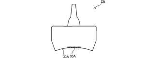
- FIG. 2 is a development view of the probe adapter according to the embodiment of the present invention.
- FIG. 3 is a diagram for explaining an operation mode of the probe according to the embodiment of the present invention.
- FIG. 4 is a diagram showing a control flow of the ultrasonic imaging apparatus according to the embodiment of the present invention.
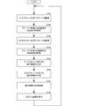
- FIG. 5 is a diagram showing a control flow in the image composition process of the ultrasonic imaging apparatus according to the embodiment of the present invention.
- FIG. 6 is a diagram for explaining a scan mode in the ultrasonic imaging apparatus according to the embodiment of the present invention.
- FIG. 7 is a diagram illustrating fragment images obtained in the linear scan mode and the sector scan mode.
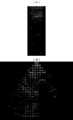
- FIG. 8 is a diagram illustrating an image obtained by synthesizing the fragment images.
- FIG. 9 is a configuration diagram showing a modification of the probe according to the embodiment of the present invention.
- FIG. 10 is a configuration diagram showing a modification of a probe adapter according to another embodiment of the present invention.
- FIG. 11 is a configuration diagram illustrating a setting example of a contact surface of a probe adapter according to another embodiment of the present invention.
- the probe 2 has a substantially columnar shape and is configured so that the operator can hold and move it.
- the probe 2 includes an ultrasonic transmission / reception surface 23.
- the ultrasonic transmission / reception surface 23 is provided on the lower end surface of the probe 2.
- the probe 2 is connected to the transmission / reception processing unit 5 of the image processing apparatus 11 via a cable connected to the upper end.
- the probe 2 receives the transmission signal from the image processing apparatus 11, transmits the ultrasonic wave from the ultrasonic transmission / reception surface 23, and receives the ultrasonic wave at the ultrasonic transmission / reception surface 23, thereby achieving the ultrasonic reception level.
- the corresponding received signal is output to the image processing apparatus 11.
- the fixing portion 32 includes a through hole extending vertically from the upper surface of the probe adapter 3 and fixes the probe 2 by contacting the grip portion 22 of the probe 2 inside the through hole.
- the probe adapter 3 further includes an attaching / detaching part 36 that can be attached to and detached from the housing part 31.
- the detachable part 36 is a member that constitutes a part on the lower surface side of the probe adapter 3.
- the detachable part 36 is configured to be detachable from the probe adapter 3 using a magnet or the like.
- the lower surface of the detachable portion 36 is configured as a contact surface 33.
- the contact surface 33 is recessed in a groove shape and has a shape that substantially coincides with the surface of the imaging target having a ridge-like bulge such as a thigh.
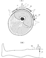
- FIG. 3A is a schematic view of the cross section of the thigh viewed from the vertical direction
- FIG. 3B is a schematic view of the thigh viewed from the side.
- the contact surface 33 has a shape along the outer periphery of the cross section 101 of the thigh 100, the contact area between the contact surface 33 and the surface of the thigh 100 is the ultrasonic transmission / reception surface 23 of the probe 2. And the contact area between the thigh 100 and the surface of the thigh 100. Therefore, as shown in FIG. 3A, the ultrasonic transmission / reception surface 23 and the thigh 100 are maintained while the cross section 101 is viewed from the vertical direction and the angle of the probe 2 with respect to the outer periphery of the cross section 101 is maintained substantially vertical. The operator can easily move the probe 2 while maintaining a large contact area with the surface of the probe 2. In addition, as shown in FIG. 3B, the operator can view the thigh 100 from the side and keep the probe 2 tilted at a certain angle with respect to the surface of the thigh 100 while the operator holds the probe 2. Can be moved easily.
- the image processing apparatus 11 shown in FIG. 1 includes a transmission / reception processing unit 5, an image display unit 8, a control unit 9, and an interface 10.
- the control unit 9 includes a fragment image generation unit 6 and an image synthesis unit 7.
- the control unit 9 includes a CPU and a storage unit.
- the fragment image generation unit 6 and the image synthesis unit 7 are executed as software by executing an ultrasonic imaging program installed in a storage unit (not shown) by the CPU.
- the fragment image generation unit 6 generates a fragment image obtained by partially imaging the imaging target based on the reception signal output from the transmission / reception processing unit 5 by image conversion processing according to the driving method of the probe 2. As shown in FIG. 3, while the probe 2 is moved along the surface of the thigh 100, the fragment image generating unit 6 is based on the received signal repeatedly input from the transmission / reception processing unit 5. A plurality of fragment images obtained by capturing the cross section 101 of the image from various directions are generated together with angle information.
- the image display unit 8 receives the image signal of the image synthesized by the image synthesis unit 7 from the control unit 9 and displays the image.
- the image composition unit 7 acquires the output signal of the angle sensor 4 and acquires the tilt angle of the probe 2 from the vertical direction (S111). Next, the image composition unit 7 rotates the fragment image obtained in the linear scan mode acquired from the fragment image generation unit 6 based on the tilt angle (S112).
- the image composition unit 7 acquires an image obtained by past image composition processing from a storage unit or the like, and composes the fragment image rotated by the above processing with the image (S113).
- feature quantities such as luminance distribution are detected for each part included in the past synthesized image and the rotated fragment image, and the matching score between the feature quantities is calculated in the past.
- the position where the fragment image should be superimposed on the image is specified.
- the luminance information in the fragment image is overwritten at the specified position. Note that the luminance information to be overwritten may be obtained by calculation or the like based on the luminance information in the image synthesized in the past and the luminance information in the fragment image.
- the ultrasonic imaging apparatus 1 can capture a wide range of the cross section of the object to be imaged using ultrasonic waves, and is perpendicular to the outer periphery in the cross section of the object to be imaged. It is possible to synthesize an image that is clearly captured up to the contour portion of the internal tissue (quadriceps etc.) extending in the direction. Therefore, based on this image, it is possible to accurately grasp the shape and thickness (muscle amount) of the internal tissue (quadriceps etc.) in the object to be imaged.
- the fragment image inclination amount detected by the angle sensor is used for the composition of the fragment image in the image composition processing.
- the fragment image inclination amount is used in the other processing. You can also For example, instead of synthesizing all the fragment images, it is possible to extract a fragment image when the amount of inclination changes beyond a certain amount and combine only the extracted fragment images. In this way, it is possible to reduce the number of times of image composition, and it is possible to reduce the calculation cost and the image storage capacity in the ultrasonic imaging apparatus.
- the probe adapter 3C shown in FIG. 10 (B) includes a housing part 31C and a fixing part 39C.
- the casing 31C is configured as a contact surface 33C whose lower surface is shaped along the outer periphery of the cross section of the object to be imaged.
- the housing portion 31C has a margin in the size of the opening to which the probe 2 is attached, and is configured so that the probe 2 can be moved to an arbitrary angle simply by inserting the probe 2 into the opening.
- fixed part 39C is comprised so that the probe 2 inserted in opening can be fixed with arbitrary angles.
- variable angle portion and the fixed portion are provided in the probe adapter.
- the above-described variable angle portion and the fixed portion are provided in the probe itself without using the probe adapter, and the contact surface is provided by the probe itself. And the angle between the ultrasonic transmission and reception surface can be adjusted.
Landscapes
- Health & Medical Sciences (AREA)
- Life Sciences & Earth Sciences (AREA)
- Physics & Mathematics (AREA)
- Engineering & Computer Science (AREA)
- Medical Informatics (AREA)
- Molecular Biology (AREA)
- Radiology & Medical Imaging (AREA)
- Nuclear Medicine, Radiotherapy & Molecular Imaging (AREA)
- Biomedical Technology (AREA)
- Heart & Thoracic Surgery (AREA)
- Biophysics (AREA)
- Pathology (AREA)
- Surgery (AREA)
- Animal Behavior & Ethology (AREA)
- General Health & Medical Sciences (AREA)
- Public Health (AREA)
- Veterinary Medicine (AREA)
- Acoustics & Sound (AREA)
- Ultra Sonic Daignosis Equipment (AREA)
- Computer Vision & Pattern Recognition (AREA)
Abstract
Description
2:プローブ
3,3B,3C,3D:プローブアダプタ
4:角度センサ
5:送受処理部
6:断片画像生成部
7:画像合成部
8:画像表示部
23:超音波送受面
32:固定部
33:当接面
Claims (15)
- 被撮像物の横断面の外周に沿う形状の当接面と、
超音波送受面を有するプローブを所定の角度で固定し、前記プローブの超音波送受面を前記当接面側に露出させる固定部と、を備えた、
プローブアダプタ。 - 請求項1に記載のプローブアダプタであって、
前記当接面は、前記固定部に固定される前記プローブの超音波送受面に対して傾いている、プローブアダプタ。 - 請求項1または請求項2に記載のプローブアダプタであって、
前記当接面側の部分が着脱自在に構成された、プローブアダプタ。 - 請求項1または請求項2に記載のプローブアダプタであって、
前記当接面が前記被撮像物の表面に対して回動自在に構成された、プローブアダプタ。 - 請求項1または請求項2に記載のプローブアダプタであって、
前記超音波送受波面が前記被撮像物の表面に対して回動自在に構成された、プローブアダプタ。 - 請求項1乃至請求項5のいずれかに記載のプローブアダプタと、前記プローブアダプタに所定の角度で固定されるプローブと、
前記プローブから前記被撮像物の内部に超音波を繰り返し送信し、前記超音波を送信するたびに前記被撮像物の内部で反射した超音波を前記プローブで受信する送受処理部と、
前記プローブで受信した前記超音波に基づいて前記被撮像物の内部を部分的に撮像した断片画像を生成する断片画像生成部と、
を備えた、超音波撮像装置。 - 被撮像物の横断面の外周に沿う形状の当接面と、前記当接面側に露出した超音波送受面と、を有するプローブと、
前記プローブから前記被撮像物の内部に超音波を繰り返し送信し、前記超音波を送信するたびに前記被撮像物の内部で反射した超音波を前記プローブで受信する送受処理部と、
前記プローブで受信した前記超音波に基づいて前記被撮像物の内部を部分的に撮像した断片画像を生成する断片画像生成部と、
を備えた、超音波撮像装置。 - 請求項6または請求項7に記載の超音波撮像装置であって、
前記断片画像生成部が生成した複数の前記断片画像を合成する画像合成部を更に備えた、
超音波撮像装置。 - 請求項8に記載の超音波撮像装置であって、
前記送受処理部は、前記超音波送受面から帯状に延びる範囲を撮像するリニアスキャンモードで前記プローブを駆動させる状態と、前記超音波送受面から扇状に広がる範囲を撮像するセクタスキャンモードで前記プローブを駆動させる状態と、を繰り返し切り替える、
超音波撮像装置。 - 請求項8または請求項9に記載の超音波撮像装置であって、
前記超音波送受面が向く方向を検出する角度センサを更に備え、
前記画像合成部は、前記角度センサが検出した角度に基づいて、前記複数の断片画像を部分的に重ね合わせた画像を合成する、
超音波撮像装置。 - 請求項8乃至請求項10のいずれかに記載の超音波撮像装置であって、
前記画像合成部は、前記複数の断片画像それぞれに含まれている部分同士のマッチングに基づいて、前記複数の断片画像同士を部分的に重ね合わせた画像を合成する、
超音波撮像装置。 - 被撮像物の横断面の外周に沿う形状の当接面と、超音波送受面を有するプローブを固定し、前記プローブの超音波送受面を前記当接面側に露出させる固定部とを備えたプローブアダプタに固定されるプローブから、前記被撮像物の内部に超音波を繰り返し送信し、前記超音波を送信するたびに前記被撮像物の内部で反射した超音波をプローブで受信する送受処理ステップと、
前記送受処理ステップで受信した前記超音波に基づいて前記被撮像物の内部を部分的に撮像した断片画像を生成する断片画像生成ステップと、
前記断片画像生成ステップで生成した複数の前記断片画像を合成する画像合成ステップと、を実行する超音波撮像方法。 - 被撮像物の横断面の外周に沿う形状の当接面と、前記当接面側に露出した超音波送受面とを有するプローブから、前記被撮像物の内部に超音波を繰り返し送信し、前記超音波を送信するたびに前記被撮像物の内部で反射した超音波をプローブで受信する送受処理ステップと、
前記送受処理ステップで受信した前記超音波に基づいて前記被撮像物の内部を部分的に撮像した断片画像を生成する断片画像生成ステップと、
前記断片画像生成ステップで生成した複数の前記断片画像を合成する画像合成ステップと、を実行する超音波撮像方法。 - 被撮像物に送信した超音波が前記被撮像物の内部で反射して得られる超音波から前記被撮像物の内部を撮像する処理をコンピュータに実行させる超音波撮像プログラムであって、
前記コンピュータに、
前記被撮像物の横断面の外周に沿う形状の当接面と、超音波送受面を有するプローブを所定の角度で固定し、前記プローブの超音波送受面を前記当接面側に露出させる固定部とを備えたプローブアダプタに固定されるプローブから、前記被撮像物の内部に超音波を繰り返し送信し、前記超音波を送信するたびに前記被撮像物の内部で反射した超音波をプローブで受信する送受処理ステップと、
前記送受処理ステップで受信した前記超音波に基づいて前記被撮像物の内部を部分的に撮像した断片画像を生成する断片画像生成ステップと、
前記断片画像生成ステップで生成した複数の前記断片画像を合成する画像合成ステップと、
を実行させる超音波撮像プログラム。 - 被撮像物に送信した超音波が前記被撮像物の内部で反射して得られる超音波から前記被撮像物の内部を撮像する処理をコンピュータに実行させる超音波撮像プログラムであって、
前記コンピュータに、
前記被撮像物の横断面の外周に沿う形状の当接面と、前記当接面側に露出した超音波送受面とを備えたプローブから、前記被撮像物の内部に超音波を繰り返し送信し、前記超音波を送信するたびに前記被撮像物の内部で反射した超音波をプローブで受信する送受処理ステップと、
前記送受処理ステップで受信した前記超音波に基づいて前記被撮像物の内部を部分的に撮像した断片画像を生成する断片画像生成ステップと、
前記断片画像生成ステップで生成した複数の前記断片画像を合成する画像合成ステップと、
を実行させる超音波撮像プログラム。
Priority Applications (4)
| Application Number | Priority Date | Filing Date | Title |
|---|---|---|---|
| CN201680041129.4A CN107835663B (zh) | 2015-07-13 | 2016-06-07 | 探头附加器、超声波摄像装置、超声波摄像方法及存储介质 |
| EP16824173.5A EP3323352B1 (en) | 2015-07-13 | 2016-06-07 | Probe adapter, ultrasonic imaging device, ultrasonic imaging method, and ultrasonic imaging program |
| US15/744,729 US11147534B2 (en) | 2015-07-13 | 2016-06-07 | Probe adapter, ultrasonic imaging apparatus, ultrasonic imaging method and ultrasonic imaging program |
| JP2017528328A JP6600685B2 (ja) | 2015-07-13 | 2016-06-07 | プローブアダプタ、超音波撮像装置、超音波撮像方法、および、超音波撮像プログラム |
Applications Claiming Priority (2)
| Application Number | Priority Date | Filing Date | Title |
|---|---|---|---|
| JP2015-139908 | 2015-07-13 | ||
| JP2015139908 | 2015-07-13 |
Publications (1)
| Publication Number | Publication Date |
|---|---|
| WO2017010193A1 true WO2017010193A1 (ja) | 2017-01-19 |
Family
ID=57757862
Family Applications (1)
| Application Number | Title | Priority Date | Filing Date |
|---|---|---|---|
| PCT/JP2016/066819 WO2017010193A1 (ja) | 2015-07-13 | 2016-06-07 | プローブアダプタ、超音波撮像装置、超音波撮像方法、および、超音波撮像プログラム |
Country Status (5)
| Country | Link |
|---|---|
| US (1) | US11147534B2 (ja) |
| EP (1) | EP3323352B1 (ja) |
| JP (1) | JP6600685B2 (ja) |
| CN (2) | CN107835663B (ja) |
| WO (1) | WO2017010193A1 (ja) |
Cited By (2)
| Publication number | Priority date | Publication date | Assignee | Title |
|---|---|---|---|---|
| WO2020039796A1 (ja) | 2018-08-22 | 2020-02-27 | 古野電気株式会社 | 超音波解析装置、超音波解析方法および超音波解析プログラム |
| WO2022239400A1 (ja) | 2021-05-11 | 2022-11-17 | 古野電気株式会社 | 超音波撮像装置、超音波撮像方法、超音波撮像システムおよび超音波撮像プログラム |
Families Citing this family (8)
| Publication number | Priority date | Publication date | Assignee | Title |
|---|---|---|---|---|
| EP3323352B1 (en) * | 2015-07-13 | 2022-03-30 | Furuno Electric Co., Ltd. | Probe adapter, ultrasonic imaging device, ultrasonic imaging method, and ultrasonic imaging program |
| US20180140277A1 (en) * | 2016-11-18 | 2018-05-24 | Clarius Mobile Health Corp. | Transducer adapters for allowing multiple modes of ultrasound imaging using a single ultrasound transducer |
| JP7112492B2 (ja) | 2018-07-13 | 2022-08-03 | 古野電気株式会社 | 超音波撮像装置、超音波撮像システム、超音波撮像方法および超音波撮像プログラム |
| DE102018125155A1 (de) * | 2018-10-11 | 2020-04-16 | Sono-Mount UG (haftungsbeschränkt) | Haltevorrichtung für eine Ultraschallsonde, eine Personenaufnahme mit einer Haltevorrichtung und Verwendung einer Haltevorrichtung |
| CN111281422B (zh) * | 2018-12-06 | 2023-03-31 | 深圳迈瑞生物医疗电子股份有限公司 | 一种探头检测方法及超声成像装置、存储介质 |
| CN110192895A (zh) * | 2019-05-28 | 2019-09-03 | 西安工业大学 | 一种超声波探头及超声波诊断装置 |
| CN112022214A (zh) * | 2020-08-06 | 2020-12-04 | 中山大学 | 一种超声生物显微镜探头及眼前段超声图像处理方法 |
| FR3126615A1 (fr) * | 2021-09-09 | 2023-03-10 | Supersonic Imagine | Dispositif pivotant pour une sonde d’échographie |
Citations (5)
| Publication number | Priority date | Publication date | Assignee | Title |
|---|---|---|---|---|
| JP2004229958A (ja) * | 2003-01-31 | 2004-08-19 | Aloka Co Ltd | 超音波画像処理装置 |
| JP2005137581A (ja) * | 2003-11-06 | 2005-06-02 | National Institute Of Advanced Industrial & Technology | 複数の超音波プローブを利用した体組織横断面の動画像撮影装置 |
| JP2008284136A (ja) * | 2007-05-17 | 2008-11-27 | Shimadzu Corp | 超音波プローブ用アタッチメント及び超音波プローブ |
| JP2011217927A (ja) * | 2010-04-08 | 2011-11-04 | Toshiba Corp | 超音波診断装置 |
| JP2012029718A (ja) * | 2010-07-28 | 2012-02-16 | Hitachi Aloka Medical Ltd | 超音波プローブアダプタ、超音波診断システムおよび超音波診断装置 |
Family Cites Families (36)
| Publication number | Priority date | Publication date | Assignee | Title |
|---|---|---|---|---|
| US4431007A (en) * | 1981-02-04 | 1984-02-14 | General Electric Company | Referenced real-time ultrasonic image display |
| JPS59111744A (ja) | 1982-12-16 | 1984-06-28 | 東一工業株式会社 | 超音波探触子及びそのアダプタ |
| US4920966A (en) * | 1986-10-02 | 1990-05-01 | Hon Edward H | Ultrasound transducer holder |
| US4962754A (en) * | 1988-01-13 | 1990-10-16 | Kabushiki Kaisha Toshiba | Shock wave treatment apparatus |
| JPH05300905A (ja) * | 1992-04-27 | 1993-11-16 | Fujitsu Ltd | 超音波音響カプラ |
| US5394877A (en) * | 1993-04-01 | 1995-03-07 | Axon Medical, Inc. | Ultrasound medical diagnostic device having a coupling medium providing self-adherence to a patient |
| US6048323A (en) * | 1995-10-02 | 2000-04-11 | Hon; Edward H. | Transducer support plate and tocodynamometer attachment system |
| US5913243A (en) | 1997-09-30 | 1999-06-15 | General Electric Co. | Ultrasonic transducer for nondestructive testing of generator field coils of dynamoelectric machines |
| JP2001087267A (ja) | 1999-09-27 | 2001-04-03 | Seikosha:Kk | 超音波体肢横断面画像撮影装置 |
| US6511427B1 (en) * | 2000-03-10 | 2003-01-28 | Acuson Corporation | System and method for assessing body-tissue properties using a medical ultrasound transducer probe with a body-tissue parameter measurement mechanism |
| US6872181B2 (en) * | 2001-04-25 | 2005-03-29 | Siemens Medical Solutions Usa, Inc. | Compound image display system and method |
| DE60307074T2 (de) * | 2002-03-27 | 2007-03-01 | Herve Bindefeld | Gerät zur untersuchung und diagnose durch doppelstethoskopischen und doppler-nachweis |
| CA2501647C (en) * | 2002-10-10 | 2013-06-18 | Visualsonics Inc. | High frequency high frame-rate ultrasound imaging system |
| US7149566B2 (en) * | 2002-10-31 | 2006-12-12 | Manoa Medical, Inc. | Soft tissue orientation and imaging guide systems and methods |
| US7914456B2 (en) * | 2003-05-30 | 2011-03-29 | Hitachi Medical Corporation | Ultrasonic probe and ultrasonic elasticity imaging device |
| US7029446B2 (en) * | 2003-10-30 | 2006-04-18 | Martin Edmund Wendelken | Standoff holder and standoff pad for ultrasound probe |
| EP1842488B1 (en) * | 2005-01-26 | 2013-07-03 | Hitachi Medical Corporation | Pressing member, ultrasonic probe and ultrasonic diagnosing device |
| FR2886533B1 (fr) * | 2005-06-03 | 2007-09-14 | Theraclion Soc Par Actions Sim | Tete d'imagerie et de traitement d'organes d'etres vivants et procede de fabrication |
| KR100671906B1 (ko) | 2005-07-08 | 2007-01-22 | 주식회사 메디슨 | 각도조절이 가능한 압박장치를 가지는 초음파 프루브 |
| US9420991B2 (en) * | 2005-09-01 | 2016-08-23 | Shih-Ping Wang | Breast ultrasound scanning device |
| US20070055159A1 (en) * | 2005-09-01 | 2007-03-08 | Shih-Ping Wang | Breast ultrasound scanning template |
| JP4850841B2 (ja) | 2005-10-04 | 2012-01-11 | 株式会社日立メディコ | 超音波探触子及びそれを用いた超音波診断装置 |
| US10561394B2 (en) * | 2006-05-02 | 2020-02-18 | U-Systems, Inc. | Ultrasound scanning and ultrasound-assisted biopsy |
| JP2008073391A (ja) * | 2006-09-25 | 2008-04-03 | Citizen Holdings Co Ltd | 超音波診断装置 |
| CN101329306B (zh) | 2008-07-11 | 2010-12-08 | 四川大学 | 适用于回转体在线超声探伤的型面自适应扫查装置 |
| US20110196238A1 (en) * | 2010-02-05 | 2011-08-11 | Jacobson Nathan A | System and Method for Fetal Heart Monitoring Using Ultrasound |
| CN201662564U (zh) | 2010-04-23 | 2010-12-01 | 北京工业大学 | 一种任意角度超声波斜探头装置 |
| WO2012042794A1 (ja) * | 2010-09-27 | 2012-04-05 | パナソニック株式会社 | 超音波診断用アダプタ、超音波診断装置、及び、超音波診断方法 |
| KR101362378B1 (ko) * | 2011-12-13 | 2014-02-13 | 삼성전자주식회사 | 초음파 진단장치용 프로브 |
| WO2013163591A1 (en) * | 2012-04-26 | 2013-10-31 | Dbmedx Inc. | Apparatus to removably secure an ultrasound probe to tissue |
| FR2993767A1 (fr) * | 2012-07-24 | 2014-01-31 | Advanced Echo Technology | Dispositif d'echographie telecommande |
| US9615815B2 (en) * | 2012-09-28 | 2017-04-11 | Clemson University Research Foundation | Devices that cooperate with ultrasound probes for muscoskeletal evaluations and related systems and methods |
| CN105188552A (zh) * | 2013-02-27 | 2015-12-23 | 王士平 | 乳房超声扫描装置 |
| JP2014195498A (ja) * | 2013-03-29 | 2014-10-16 | セイコーエプソン株式会社 | シート及び超音波測定システム |
| JP6123423B2 (ja) * | 2013-03-29 | 2017-05-10 | セイコーエプソン株式会社 | 超音波プローブ、超音波測定装置及び超音波画像装置 |
| EP3323352B1 (en) * | 2015-07-13 | 2022-03-30 | Furuno Electric Co., Ltd. | Probe adapter, ultrasonic imaging device, ultrasonic imaging method, and ultrasonic imaging program |
-
2016
- 2016-06-07 EP EP16824173.5A patent/EP3323352B1/en active Active
- 2016-06-07 WO PCT/JP2016/066819 patent/WO2017010193A1/ja active Application Filing
- 2016-06-07 CN CN201680041129.4A patent/CN107835663B/zh active Active
- 2016-06-07 CN CN201810818443.XA patent/CN108938004A/zh active Pending
- 2016-06-07 JP JP2017528328A patent/JP6600685B2/ja active Active
- 2016-06-07 US US15/744,729 patent/US11147534B2/en active Active
Patent Citations (5)
| Publication number | Priority date | Publication date | Assignee | Title |
|---|---|---|---|---|
| JP2004229958A (ja) * | 2003-01-31 | 2004-08-19 | Aloka Co Ltd | 超音波画像処理装置 |
| JP2005137581A (ja) * | 2003-11-06 | 2005-06-02 | National Institute Of Advanced Industrial & Technology | 複数の超音波プローブを利用した体組織横断面の動画像撮影装置 |
| JP2008284136A (ja) * | 2007-05-17 | 2008-11-27 | Shimadzu Corp | 超音波プローブ用アタッチメント及び超音波プローブ |
| JP2011217927A (ja) * | 2010-04-08 | 2011-11-04 | Toshiba Corp | 超音波診断装置 |
| JP2012029718A (ja) * | 2010-07-28 | 2012-02-16 | Hitachi Aloka Medical Ltd | 超音波プローブアダプタ、超音波診断システムおよび超音波診断装置 |
Non-Patent Citations (1)
| Title |
|---|
| See also references of EP3323352A4 * |
Cited By (5)
| Publication number | Priority date | Publication date | Assignee | Title |
|---|---|---|---|---|
| WO2020039796A1 (ja) | 2018-08-22 | 2020-02-27 | 古野電気株式会社 | 超音波解析装置、超音波解析方法および超音波解析プログラム |
| CN112367922A (zh) * | 2018-08-22 | 2021-02-12 | 古野电气株式会社 | 超声波分析装置、超声波分析方法、以及超声波分析程序 |
| JPWO2020039796A1 (ja) * | 2018-08-22 | 2021-08-12 | 古野電気株式会社 | 超音波解析装置、超音波解析方法および超音波解析プログラム |
| JP7179860B2 (ja) | 2018-08-22 | 2022-11-29 | 古野電気株式会社 | 超音波解析装置、超音波解析方法および超音波解析プログラム |
| WO2022239400A1 (ja) | 2021-05-11 | 2022-11-17 | 古野電気株式会社 | 超音波撮像装置、超音波撮像方法、超音波撮像システムおよび超音波撮像プログラム |
Also Published As
| Publication number | Publication date |
|---|---|
| JPWO2017010193A1 (ja) | 2018-04-26 |
| CN107835663A (zh) | 2018-03-23 |
| EP3323352B1 (en) | 2022-03-30 |
| CN108938004A (zh) | 2018-12-07 |
| CN107835663B (zh) | 2022-02-08 |
| US20180263596A1 (en) | 2018-09-20 |
| EP3323352A4 (en) | 2019-07-03 |
| US11147534B2 (en) | 2021-10-19 |
| EP3323352A1 (en) | 2018-05-23 |
| JP6600685B2 (ja) | 2019-10-30 |
Similar Documents
| Publication | Publication Date | Title |
|---|---|---|
| JP6600685B2 (ja) | プローブアダプタ、超音波撮像装置、超音波撮像方法、および、超音波撮像プログラム | |
| JP4854212B2 (ja) | 超音波診断装置 | |
| TWI520716B (zh) | 超音波成像系統、裝置及方法 | |
| JP5394299B2 (ja) | 超音波診断装置 | |
| KR101182880B1 (ko) | 영상 지시자를 제공하는 초음파 시스템 및 방법 | |
| US6837854B2 (en) | Methods and systems for using reference images in acoustic image processing | |
| US20080200807A1 (en) | Attitude-sensing ultrasound probe | |
| US20140114194A1 (en) | Ultrasound diagnosis apparatus and ultrasound probe controlling method | |
| US20170095226A1 (en) | Ultrasonic diagnostic apparatus and medical image diagnostic apparatus | |
| EP2402745B1 (en) | Ultrasound diagnosis apparatus, image processing apparatus and image processing method | |
| JP6202841B2 (ja) | 超音波診断装置 | |
| JP6767575B2 (ja) | 超音波トランスデューサ・タイル位置合わせ | |
| JP4688262B2 (ja) | 超音波診断装置 | |
| JP2005074146A (ja) | 超音波測定方法、超音波発生機構 | |
| JP5868479B2 (ja) | 超音波診断装置、超音波画像処理装置、医用画像診断装置及び医用画像処理装置 | |
| US20220087646A1 (en) | Ultrasonic periodontal probe | |
| JP2017225645A (ja) | 超音波画像表示装置及び方法、並びにプログラムを格納した記録媒体 | |
| KR101893640B1 (ko) | 십자형 또는 t자형 초음파 프로브 및 이를 이용한 초음파 진단장치 | |
| JP6224341B2 (ja) | 固定具及び超音波診断装置 | |
| JP5761933B2 (ja) | 超音波診断装置、超音波画像処理装置及び医用画像処理装置 | |
| JP6778028B2 (ja) | 医療システム及び超音波診断装置 | |
| JP2006081640A (ja) | 超音波撮像装置、画像処理装置およびプログラム | |
| JP5454885B2 (ja) | 超音波プローブ用穿刺アダプタ及び超音波診断装置 | |
| US20220233164A1 (en) | Ultrasound Probe | |
| JP6207940B2 (ja) | 超音波診断装置、医用画像処理装置および医用画像処理プログラム |
Legal Events
| Date | Code | Title | Description |
|---|---|---|---|
| 121 | Ep: the epo has been informed by wipo that ep was designated in this application |
Ref document number: 16824173 Country of ref document: EP Kind code of ref document: A1 |
|
| ENP | Entry into the national phase |
Ref document number: 2017528328 Country of ref document: JP Kind code of ref document: A |
|
| WWE | Wipo information: entry into national phase |
Ref document number: 15744729 Country of ref document: US |
|
| NENP | Non-entry into the national phase |
Ref country code: DE |
|
| WWE | Wipo information: entry into national phase |
Ref document number: 2016824173 Country of ref document: EP |