WO2017010034A1 - 燃料噴射弁 - Google Patents
燃料噴射弁 Download PDFInfo
- Publication number
- WO2017010034A1 WO2017010034A1 PCT/JP2016/002528 JP2016002528W WO2017010034A1 WO 2017010034 A1 WO2017010034 A1 WO 2017010034A1 JP 2016002528 W JP2016002528 W JP 2016002528W WO 2017010034 A1 WO2017010034 A1 WO 2017010034A1
- Authority
- WO
- WIPO (PCT)
- Prior art keywords
- valve
- outer peripheral
- valve seat
- fuel injection
- seat surface
- Prior art date
- Legal status (The legal status is an assumption and is not a legal conclusion. Google has not performed a legal analysis and makes no representation as to the accuracy of the status listed.)
- Ceased
Links
Images







Classifications
-
- F—MECHANICAL ENGINEERING; LIGHTING; HEATING; WEAPONS; BLASTING
- F02—COMBUSTION ENGINES; HOT-GAS OR COMBUSTION-PRODUCT ENGINE PLANTS
- F02M—SUPPLYING COMBUSTION ENGINES IN GENERAL WITH COMBUSTIBLE MIXTURES OR CONSTITUENTS THEREOF
- F02M51/00—Fuel-injection apparatus characterised by being operated electrically
- F02M51/06—Injectors peculiar thereto with means directly operating the valve needle
-
- F—MECHANICAL ENGINEERING; LIGHTING; HEATING; WEAPONS; BLASTING
- F02—COMBUSTION ENGINES; HOT-GAS OR COMBUSTION-PRODUCT ENGINE PLANTS
- F02M—SUPPLYING COMBUSTION ENGINES IN GENERAL WITH COMBUSTIBLE MIXTURES OR CONSTITUENTS THEREOF
- F02M61/00—Fuel-injectors not provided for in groups F02M39/00 - F02M57/00 or F02M67/00
- F02M61/04—Fuel-injectors not provided for in groups F02M39/00 - F02M57/00 or F02M67/00 having valves, e.g. having a plurality of valves in series
-
- F—MECHANICAL ENGINEERING; LIGHTING; HEATING; WEAPONS; BLASTING
- F02—COMBUSTION ENGINES; HOT-GAS OR COMBUSTION-PRODUCT ENGINE PLANTS
- F02M—SUPPLYING COMBUSTION ENGINES IN GENERAL WITH COMBUSTIBLE MIXTURES OR CONSTITUENTS THEREOF
- F02M61/00—Fuel-injectors not provided for in groups F02M39/00 - F02M57/00 or F02M67/00
- F02M61/16—Details not provided for in, or of interest apart from, the apparatus of groups F02M61/02 - F02M61/14
- F02M61/18—Injection nozzles, e.g. having valve seats; Details of valve member seated ends, not otherwise provided for
-
- F—MECHANICAL ENGINEERING; LIGHTING; HEATING; WEAPONS; BLASTING
- F02—COMBUSTION ENGINES; HOT-GAS OR COMBUSTION-PRODUCT ENGINE PLANTS
- F02M—SUPPLYING COMBUSTION ENGINES IN GENERAL WITH COMBUSTIBLE MIXTURES OR CONSTITUENTS THEREOF
- F02M69/00—Low-pressure fuel-injection apparatus ; Apparatus with both continuous and intermittent injection; Apparatus injecting different types of fuel
Definitions
- the present disclosure relates to a fuel injection valve that injects fuel into an internal combustion engine.
- a fuel injection valve in which a valve member is housed in a valve housing whose valve seat surface is reduced in diameter toward a downstream side upstream of a fuel injection hole has been widely used.
- the valve member urged by the elastic member when the valve member urged by the elastic member is separated from and seated on the valve seat surface, the fuel injection from the injection hole is intermittently performed by opening and closing the valve.
- valve member of the fuel injection valve disclosed in Patent Document 1 an inner peripheral side taper surface having a large taper angle and an outer peripheral side taper surface having a small taper angle connected to the outer peripheral side thereof are provided.
- the boundary portion of the tapered surface is separated from and seated on the tapered valve seat surface.
- the valve member of the fuel injection valve disclosed in Patent Document 2 is provided with a convex curved surface curved in a partial spherical shape with a predetermined radius of curvature, and a valve seat in which a radial intermediate portion of the convex curved surface is a tapered seat. Take off and sit against the surface.
- This disclosure is intended to provide a fuel injection valve that suppresses fuel leakage in a closed state.
- a valve housing having a nozzle hole for injecting fuel to the internal combustion engine, a valve seat surface having a diameter reduced toward the downstream side upstream of the nozzle hole, and the valve housing
- a valve member that is accommodated and is coaxially attached to and detached from the valve seat surface to urge the valve member toward the valve seat surface by opening and closing the valve and intermittently injecting fuel from the injection hole.
- a fuel injection valve having an elastic member, the valve member being provided continuously to an inner peripheral convex surface curved in a partial spherical shape with a predetermined radius of curvature and an outer peripheral side of the inner peripheral convex surface.
- an outer peripheral convex surface curved in a partial spherical shape with a smaller radius of curvature than the inner peripheral convex surface, and the boundary between the inner peripheral convex surface and the outer peripheral convex surface faces the valve seat surface. It protrudes so that it can be seated.
- the outer peripheral side of the inner peripheral convex curved surface curved in a partial spherical shape with a predetermined radius of curvature has a partial spherical shape with a smaller radius of curvature than the inner peripheral convex curved surface.
- a curved outer peripheral convex curved surface is provided continuously.
- the boundary portion is within the range where wear due to excessive increase in dynamic surface pressure can be suppressed during valve closing operation where the boundary portion collides with the valve seat surface. It is possible to increase the static surface pressure when the valve is seated on the seat surface. Therefore, fuel leakage from between the boundary portion and the valve seat surface can be suppressed in the valve closed state.
- the nozzle hole in the first aspect injects fuel into the intake port of the internal combustion engine.
- FIG. 1 is a configuration diagram showing an internal combustion engine equipped with a fuel injection valve according to an embodiment.
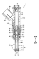
- FIG. 2 is a longitudinal sectional view showing a fuel injection valve according to an embodiment
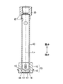
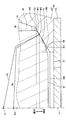
- FIG. 3 is a longitudinal sectional view showing a partially enlarged view of FIG. 4 is an enlarged longitudinal sectional view showing the contact portion of FIGS.
- FIG. 5 is a schematic diagram for explaining the configuration of the contact portion of FIGS.
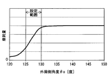
- FIG. 6 is a graph for explaining the configuration of the contact portion of FIGS.
- FIG. 7 is a schematic diagram for explaining the principle of deposit adhesion to the outer circumferential convex curved surface of FIG. FIG.
- FIG. 8 is a schematic diagram for explaining the volume growth of deposits attached to the outer circumferential convex curved surface of FIG.
- FIG. 9 is a graph for explaining the adhesion width of the deposit that adheres to the outer circumferential convex curved surface of FIG.
- FIG. 10 is a graph for explaining the configuration of the contact portion of FIGS.
- FIG. 11 is a graph for explaining the configuration of the contact portion of FIGS.
- FIG. 12 is a graph for explaining the correlation between the dynamic surface pressure and the wear amount;
- FIG. 13 is a longitudinal sectional view showing a modification of FIG.
- FIG. 14 is a longitudinal sectional view showing a modification of FIG.
- FIG. 15 is a longitudinal sectional view showing a modification of FIG.
- a fuel injection valve 1 is mounted on an internal combustion engine 2 that burns gasoline in a cylinder 2a.
- the fuel injection valve 1 injects the fuel sucked into the cylinder 2a together with the intake air into the intake port 2b through which the intake air flows.
- the fuel injection valve 1 includes a valve housing 10, a fixed core 20, a movable core 30, a valve member 40, an elastic member 50, and a drive unit 60.
- the valve housing 10 includes a pipe member 11, a valve seat member 12, a nozzle hole member 13, and the like.
- the cylindrical pipe member 11 has a first magnetic part 110, a nonmagnetic part 111, and a second magnetic part 112 in this order from the valve opening side to the valve closing side in the axial direction.
- the magnetic parts 110 and 112 made of a metal magnetic material and the nonmagnetic part 111 made of a metal nonmagnetic material are coupled coaxially by, for example, laser welding. Due to this coupling structure, the nonmagnetic portion 111 blocks a short circuit of magnetic flux between the first magnetic portion 110 and the second magnetic portion 112.
- the first magnetic part 110 forms a supply inlet 14 that receives the supply of fuel from the fuel pump 3 (see FIG. 1).
- a valve seat member 12 made of a cylindrical metal is coaxially fitted and fixed to the second magnetic portion 112.
- the valve seat member 12 forms a fuel passage 15 in cooperation with the pipe member 11 so that the fuel guided from the upstream side flows to the downstream side.
- the valve seat member 12 has a valve seat surface 16 exposed to the fuel passage 15 as shown in FIGS.
- the valve seat surface 16 is formed in a tapered surface shape (conical surface shape) having a constant diameter reduction rate as a reduced diameter shape that decreases in diameter toward the downstream side of the fuel passage 15.
- the nozzle member 13 made of a bottomed cylindrical metal is coaxially fitted and fixed to the valve seat member 12 on the side opposite to the second magnetic portion 112.
- the nozzle hole member 13 has a plurality of nozzle holes 17 at the bottom. Each nozzle hole 17 communicates with the fuel passage 15 on the downstream side of the valve seat surface 16 and opens radially toward the intake port 2b (see FIG. 1).
- the fixed core 20 made of a cylindrical metal magnetic body is coaxially fitted and fixed to the first magnetic part 110 and the nonmagnetic part 111.
- An adjusting pipe 22 made of a cylindrical metal is press-fitted and fixed coaxially to the fixed core 20.
- the fixed core 20 forms a fixed passage 24 together with the adjusting pipe 22 so that the fuel flowing in from the upstream supply inlet 14 flows out to the downstream side.
- the movable core 30 made of a cylindrical metal magnetic body is accommodated coaxially in the nonmagnetic portion 111 and the second magnetic portion 112.
- the movable core 30 can reciprocate to both sides in the axial direction on the valve closing side with respect to the fixed core 20.
- the valve member 40 made of a bottomed cylindrical metal nonmagnetic material is accommodated coaxially across the second magnetic portion 112 and the valve seat member 12. As shown in FIGS. 2 and 3, the valve member 40 is fitted and fixed to the movable core 30 from the valve closing side. Thereby, the valve member 40 can be reciprocated integrally with the movable core 30 to both sides in the axial direction along its own valve center line Lv.
- the valve member 40 forms a movable passage 42 together with the movable core 30 so as to guide the fuel flowing out from the upstream fixed passage 24 to the downstream fuel passage 15.
- the valve member 40 has a contact portion 44 that reciprocates on the upstream side of the valve seat surface 16 at the bottom portion on the valve closing side. As shown in FIGS. 2 to 4, the valve member 40 coaxially separates and seats the abutting portion 44 with respect to the valve seat surface 16 having the reduced diameter shape on the upstream side of all the nozzle holes 17. Specifically, the valve member 40 moves to the valve opening side, thereby causing the contact portion 44 to be separated from the valve seat surface 16 over the entire circumference. As a result, the valve member 40 is opened, and each nozzle hole 17 communicates with the fuel passage 15. Therefore, fuel is injected from each nozzle hole 17 into the intake port 2b (see FIG. 1).
- valve member 40 moves to the valve closing side to seat the contact portion 44 on the valve seat surface 16 over the entire circumference. As a result, the valve member 40 is closed and each injection hole 17 is disconnected from the fuel passage 15, so that fuel injection from each injection hole 17 is stopped. As described above, the valve member 40 can be opened and closed by opening and closing the valve seat surface 16 so that fuel injection from each nozzle hole 17 can be intermittently performed.
- the elastic member 50 is a compression coil spring made of metal, and is accommodated coaxially in the passages 24 and 42 in the fixed core 20 and the movable core 30.
- the elastic member 50 is sandwiched between the adjusting pipe 22 in the fixed core 20 and the movable core 30.
- the elastic member 50 generates an elastic restoring force in response to compression between the elements 22 and 30, thereby attaching the movable core 30 and the valve member 40 toward the valve seat surface 16 on the valve closing side. Rush. That is, the elastic restoring force generated by the elastic member 50 becomes a biasing force that biases the movable core 30 and the valve member 40.
- the driving unit 60 includes a solenoid coil 61, a spool 62, a terminal 63, a connector 64, and the like.
- the solenoid coil 61 is formed by winding a metal wire around a spool 62 made of a cylindrical resin.
- the solenoid coil 61 is coaxially fitted and fixed to the magnetic portions 110 and 112 and the nonmagnetic portion 111 via the spool 62.
- a terminal 63 made of metal is embedded in a connector 64 made of resin, and electrically connects the external control circuit 4 (see FIG. 1) and the internal solenoid coil 61. With this electrical connection, the energization of the solenoid coil 61 can be controlled by the control circuit 4.
- the solenoid coil 61 energized by the control circuit 4 is excited to excite the first magnetic part 110, the fixed core 20, the movable core 30, and the second magnetism.
- the magnetic flux is guided to the portion 112.
- a magnetic attractive force is generated between the cores 20 and 30 facing each other so as to attract the movable core 30 toward the fixed core 20 on the valve opening side.
- the movable core 30 is driven together with the valve member 40 to the valve opening side against the urging force of the elastic member 50, the movable core 30 is brought into contact with and locked to the fixed core 20.
- the valve member 40 separates the contact portion 44 from the valve seat surface 16, so that fuel is injected from each injection hole 17.
- FIG. 4 illustrates one of longitudinal sections that are cut including a valve center line Lv assumed to extend at the radial center of the valve member 40. Therefore, in the following, an arbitrary longitudinal section including the longitudinal section of FIG. 4 regarding the valve member 40 is simply referred to as a longitudinal section.
- the valve member 40 has a valve outer peripheral surface 46 that extends straight in a cylindrical shape centered on the valve center line Lv on the outer peripheral side and the valve opening side of the contact portion 44.
- the valve member 40 has a convex curved surface or a flat tip surface 47 on the inner peripheral side and the valve closing side of the contact portion 44.
- the valve member 40 has two types of convex curved surfaces 440 and 441 that are curved in a partial spherical shape, coaxially over the entire circumference of the contact portion 44.
- the inner circumferential convex surface 440 is continuous from the tip surface 47 to the outer circumferential side and the valve opening side.
- the tip surface 47 positioned downstream of the inner circumferential convex surface 440 provides a flat sac chamber 150 that guides fuel to each nozzle hole 17 when the valve is opened as part of the fuel passage 15. It is formed between the housing 10 and the nozzle hole member 13.
- the inner peripheral convex curved surface 440 has a predetermined curvature radius Ri, and has a circular arc shape in which the curvature center position Pi is defined on the longitudinal section.
- the curvature center position Pi of the inner peripheral convex curved surface 440 is defined on the valve center line Lv of the valve member 40. That is, the inner peripheral convex surface 440 is aligned with the valve outer peripheral surface 46 so as to be aligned with the valve center line Lv.
- the outer circumferential convex surface 441 is continuous from the valve outer circumferential surface 46 to the inner circumferential side and the valve closing side. As a result, the outer circumferential convex curved surface 441 forms a bent portion 442 that bends sharply from the valve outer circumferential surface 46 over the entire circumference. Moreover, the outer peripheral convex curved surface 441 is continuous from the inner peripheral convex curved surface 440 to the inner peripheral side and the valve opening side. Thereby, the outer peripheral convex curved surface 441 forms a boundary portion 443 with the inner peripheral convex convex surface 440 over the entire circumference.
- the boundary portion 443 has a shape that protrudes toward the valve seat surface 16 of the valve seat member 12 in the valve housing 10 over the entire circumference.
- the outer peripheral convex curved surface 441 has a curvature radius Ro smaller than the curvature radius Ri of the inner peripheral convex curved surface 440, and has a circular arc shape in which the curvature center position Po is defined on the vertical cross section.
- the curvature center position Po of the outer circumferential convex surface 441 is defined on the valve center line Lv on the valve closing side with respect to the curvature center position Pi of the inner circumferential convex surface 440.
- the outer peripheral convex curved surface 441 is aligned with the valve outer peripheral surface 46 so as to be aligned with the valve center line Lv.
- the protruding boundary portion 443 formed by the outer circumferential convex curved surface 441 and the inner circumferential convex curved surface 440 is also aligned with the valve outer circumferential surface 46 so as to be aligned with the valve center line Lv. Therefore, in the present embodiment, the boundary portion 443 can be separated from the tapered valve seat surface 16 having a taper angle of about 120 degrees in FIG. It has become. As a result, the alignment and stability of the boundary portion 443 seated on the tapered valve seat surface 16 is enhanced.
- a tangent that is assumed to pass through the boundary portion 443 with respect to the outer circumferential convex curved surface 441 is defined as an outer circumferential tangent Lo.
- an angle formed by the outer circumferential side tangent Lo and the valve outer circumferential surface 46 on the longitudinal section is defined as an outer circumferential side angle ⁇ o.
- the outer peripheral angle ⁇ o is in the range of 125 degrees or more and 130 degrees or less, preferably in the range of 125 degrees or more and 128 degrees or less, particularly preferably 125. It is set to about 5 degrees.
- an outer peripheral side angle ⁇ o of 125 degrees or more is employed.
- the boundary portion 443 with increased sharpness collides with the valve seat surface 16 and is easily worn as shown in FIG.
- an outer peripheral side angle ⁇ o of 130 degrees or less is employed.
- the amount of wear shown on the vertical axis in FIG. 6 is represented by the maximum depth in the axial direction of the dent caused by wear of the valve seat surface 16 by a predetermined number of valve closing operations under a constant fuel pressure.
- the adhesion width Wd from the bent portion 442 shown in FIG. 8 tends to saturate when the number of repeated valve opening operations increases to some extent. This is presumably because the accumulation of the deposit D causes the outer peripheral side angle ⁇ o in the vicinity of the bent portion 442 to be apparently increased, thereby making it difficult for the fuel flow to stay.
- the deposit width Wd of the deposit D described above is expressed in the present embodiment by the distance between the bent portion 442 and the portion Pd farthest from the bent portion 442 in the deposit D on the vertical cross section shown in FIG. Is done.
- the distance Wo between the bent portion 442 and the boundary portion 443 is determined from the adhesion width Wd of the deposit D as the width Wo of the outer circumferential convex curved surface 441 on the longitudinal section shown in FIG. Must be set larger. If the width Wo of the outer peripheral convex surface 441 is smaller than the adhesion width Wd of the deposit D, the valve closing surface in which the boundary portion 443 collides with the valve seat surface 16 between the boundary portion 443 and the valve seat surface 16. This is because the deposit D is bitten at the time of operation, leading to fuel leakage.
- the width Wo of the outer circumferential convex surface 441 and the adhesion width Wd of the deposit D are respectively the outer circumference.
- a correlation as shown in FIG. 10 appears with the side angle ⁇ o. Therefore, the setting of the outer peripheral side angle ⁇ o of 125 degrees or more based on this correlation is necessary not only from the viewpoint of static surface pressure as described above but also from the viewpoint of deposit D, in order to suppress fuel leakage. It turns out that it is a structure.
- the correlation in FIG. 10 appears when the difference in radial distance from the valve center line Lv for each of the bent portion 442 and the boundary portion 443 is secured to 0.09 mm or more.
- a tangent line that passes through the boundary portion 443 with respect to the inner peripheral convex curved surface 440 is defined as an inner peripheral tangent line Li.
- the angle formed by the inner peripheral side tangent Li and the valve outer peripheral surface 46 on the longitudinal section is defined as an inner peripheral side angle ⁇ i.
- the angle difference ⁇ between the inner peripheral angle ⁇ i and the outer peripheral angle ⁇ o is 4 degrees or more and 10 It is set within the range of degrees.
- an angle difference ⁇ of 4 degrees or more is employed.
- an angle difference ⁇ of 10 degrees or less is employed together with an outer peripheral side angle ⁇ o of 130 degrees or less.
- the fuel leakage amount shown on the vertical axis in FIG. 11 is represented by the volume of fuel that leaks within a predetermined time from between the boundary portion 443 and the valve seat surface 16 in the valve closed state, that is, the volume flow rate.
- the dynamic surface pressure realized by the present embodiment with the above configuration will be described.
- the maximum value of the dynamic surface pressure causes a correlation as shown in FIG. 12 to appear between the amount of wear and the valve member in a state where the valve member is inclined most in the range of tolerance and is off-axis. Therefore, in the present embodiment, the dynamic surface pressure generated between the boundary portion 443 and the valve seat surface 16 during the valve closing operation in which the boundary portion 443 collides with the valve seat surface 16 is limited. That is, in the present embodiment, the outer peripheral angle ⁇ o is 130 degrees or less and the angular difference ⁇ so as to realize a dynamic surface pressure that is suppressed to 1000 MPa or less while avoiding a dynamic surface pressure exceeding 1000 MPa where the amount of wear becomes significant. Is set to 10 degrees or less.
- FIG. 12 shows the correlation between the maximum value of the dynamic surface pressure when the inclination of the valve member is 0.1 degree and the amount of wear expressed in the same manner as in FIG.
- a partial spherical surface having a radius of curvature Ro smaller than that of the inner peripheral convex surface 440 is formed on the outer peripheral side of the inner peripheral convex curved surface 440 curved in a partial spherical shape with a predetermined curvature radius Ri.
- a convex curved surface 441 on the outer peripheral side that is curved like a circle is provided continuously. As a result, the boundary 443 between the inner circumferential convex surface 440 and the outer circumferential convex surface 441 protrudes toward the valve seat surface 16, but has a shape with reduced sharpness.
- the outer peripheral side angle ⁇ o formed by the outer peripheral side tangent Lo of the outer peripheral convex surface 441 passing through the boundary portion 443 and the valve outer peripheral surface 46 is set to 125 degrees or more.
- the outer peripheral convex curved surface 441 can secure a larger gap 151 (see FIG. 4) between the boundary portion 443 and the outer peripheral side between the valve seat surface 16 whose diameter decreases toward the downstream side.
- the outer peripheral convex curved surface 441 on the outer peripheral side with respect to the boundary portion 443 is different from the valve seat surface 16. It can suppress that static surface pressure falls by contact
- a shape with reduced sharpness can be secured at the boundary portion 443 between the outer peripheral convex surface 441 and the inner peripheral convex surface 440. Therefore, between the boundary part 443 and the valve seat surface 16, the certainty of the function which suppresses the abrasion resulting from the excessive increase in dynamic surface pressure can be improved. Therefore, it is possible to contribute to suppressing fuel leakage from between the boundary portion 443 and the valve seat surface 16 in the valve closed state.
- the inner peripheral side angle ⁇ i formed by the inner peripheral side tangent Li of the inner peripheral convex surface 440 passing through the boundary portion 443 and the valve outer peripheral surface 46 is the outer peripheral side.
- the difference from the side angle ⁇ o is set to 4 degrees or more.
- the difference between the inner peripheral side angle ⁇ i and the outer peripheral side angle ⁇ o is set to 10 degrees or less on the longitudinal section of the valve member 40.
- the boundary portion 443 between the inner circumferential convex surface 440 and the outer circumferential convex surface 441 has a shape in which sharpness is reliably reduced. Therefore, between the boundary part 443 and the valve seat surface 16, the reliability of the function which suppresses the abrasion resulting from the excessive increase in dynamic surface pressure can also be improved. Therefore, it is possible to greatly contribute to suppressing fuel leakage from between the boundary portion 443 and the valve seat surface 16 in the valve closed state.
- the dynamic surface pressure generated between the boundary portion 443 and the valve seat surface 16 is suppressed to 1000 Mpa or less during the valve closing operation in which the boundary portion 443 collides with the valve seat surface 16. Become. According to this, since the function of suppressing wear can be reliably exhibited, it is possible to greatly contribute to suppressing fuel leakage from between the boundary portion 443 and the valve seat surface 16 in the valve closed state.
- the outer circumferential convex surface 441 having a small radius of curvature Ro is bent from the valve outer circumferential surface 46 on the longitudinal section of the valve member 40 by the fuel injection valve 1, the diameter thereof is reduced toward the downstream side.
- a larger gap 151 (see FIG. 4) can be secured between the valve seat surface 16 and the valve seat surface 16 toward the outer peripheral side. Therefore, even if the valve member 40 is inclined with respect to the valve seat surface 16 due to the bias of the urging force by the elastic member 50, the bent portion 442 formed by the outer peripheral convex curved surface 441 and the valve outer peripheral surface 46 is the valve seat. It is possible to prevent the static surface pressure in the closed state from being lowered by contacting the surface 16. According to this, it becomes possible to contribute to suppressing fuel leakage from between the boundary portion 443 and the valve seat surface 16 in the valve closed state.
- the boundary portion 443 A function relating to dynamic surface pressure and static surface pressure can be exerted between the valve seat surface 16 and the valve seat surface 16. Therefore, even when the fuel pressure of the injected fuel is relatively low, fuel leakage in the closed state can be suppressed.
- the outer peripheral side angle ⁇ o may be set outside the range of 125 degrees or more and 130 degrees or less as long as the effect of the present disclosure can be obtained.
- the angle difference ⁇ may be set outside the range of 4 degrees or more and 10 degrees or less as long as the operational effects of the present disclosure can be obtained.
- dynamics generated between the boundary portion 443 and the valve seat surface 16 during the valve closing operation in which the boundary portion 443 collides with the valve seat surface 16 are performed.
- the surface pressure may be set to a surface pressure exceeding 1000 MPa.
- an additional surface 444 that connects the surfaces 441 and 46 is provided on the outer peripheral side of the outer peripheral convex curved surface 441 and the inner peripheral side of the valve outer peripheral surface 46 in the contact portion 44. It may be formed. As shown in FIG. 13, the additional surface 444 is formed in a convex curved surface shape such as a partial spherical surface having a cross-sectional arc shape with a smaller radius of curvature than the outer convex curved surface 441 on the vertical cross section. Also good. Alternatively, although the additional surface 444 is not illustrated, it may be formed in a tapered surface shape, for example. In FIG. 13, a boundary portion between the outer peripheral convex curved surface 441 and the additional surface 444 is indicated by a reference numeral 445.
- valve seat surface 16 may be formed in a tapered surface shape with a taper angle ⁇ s other than 120 degrees. Further, as shown in FIG. 14, in the sixth modification, the valve seat surface 16 may be formed in a curved surface shape in which the diameter reduction rate that decreases toward the downstream side of the fuel passage 15 decreases toward the downstream side. Furthermore, as shown in FIG. 15, in the modified example 7, the valve seat surface 16 may be formed in a curved surface shape in which the diameter reduction rate that decreases toward the downstream side of the fuel passage 15 increases toward the downstream side. .
- the present disclosure may be applied to a fuel injection valve that injects fuel into a cylinder of a gasoline internal combustion engine.
- the present disclosure may be applied to a fuel injection valve that injects fuel into a cylinder of a diesel internal combustion engine.
Landscapes
- Engineering & Computer Science (AREA)
- Chemical & Material Sciences (AREA)
- Combustion & Propulsion (AREA)
- Mechanical Engineering (AREA)
- General Engineering & Computer Science (AREA)
- Fuel-Injection Apparatus (AREA)
Abstract
燃料噴射弁は、内燃機関へ燃料を噴射する噴孔(17)、並びに噴孔(17)よりも上流側において下流側へ向かって縮径した弁座面(16)を、有する弁ハウジング(10)と、弁ハウジング(10)内に収容されており、弁座面(16)に対して同軸上に離着座することにより、開閉弁して噴孔(17)からの燃料噴射を断続させる弁部材(40)と、弁部材(40)を弁座面(16)へ向かって付勢している弾性部材とを、備える。弁部材(40)は、所定の曲率半径(Ri)をもって部分球面状に湾曲した内周側凸曲面(440)と、内周側凸曲面(440)の外周側に連なって設けられており、内周側凸曲面(440)よりも小さな曲率半径(Ro)をもって部分球面状に湾曲した外周側凸曲面(441)とを、有する。内周側凸曲面(440)と外周側凸曲面(441)との境界部(443)は、弁座面(16)へ向かって離着座可能に突出している。
Description
本出願は、2015年7月14日に出願された日本特許出願番号2015‐140771号および2016年2月29日に出願された日本特許出願番号2016‐37257号に基づくもので、ここにその記載内容を援用する。
本開示は、内燃機関へ燃料を噴射する燃料噴射弁に関する。
従来、燃料を噴射する噴孔よりも上流側において、弁座面が下流側へ向かって縮径した弁ハウジング内に弁部材が収容されている燃料噴射弁は、広く利用されている。こうした燃料噴射弁では、弾性部材により付勢された弁部材が弁座面に対して離着座することで、開閉弁して噴孔からの燃料噴射が断続されることになる。
例えば、特許文献1に開示される燃料噴射弁の弁部材では、大テーパ角度の内周側テーパ面と、その外周側に連なった小テーパ角度の外周側テーパ面とが設けられており、それらテーパ面の境界部がテーパ状の弁座面に対して離着座する。また、特許文献2に開示される燃料噴射弁の弁部材では、所定の曲率半径をもって部分球面状に湾曲した凸曲面が設けられており、当該凸曲面の径方向中間部がテーパ状の弁座面に対して離着座する。
しかし、特許文献1に開示される燃料噴射弁によると、内周側テーパ面と外周側テーパ面との境界部は、弁座面へ向かって尖鋭状に突出している。そのため、弾性部材により弁座面へと向かって付勢される弁部材では、閉弁作動時に尖鋭状の境界部が弁座面と衝突することで、それら境界部及び弁座面間に生じる動的面圧が過度に増大する。こうした動的面圧の増大は、境界部や弁座面を摩耗させることから、閉弁作動後の閉弁状態において境界部及び弁座面間からの燃料漏れを招くおそれがあった。
一方、特許文献2に開示される燃料噴射弁によると、滑らかな部分球面状の凸曲面が弁座面に着座することで、閉弁状態が構築される。そのため、弾性部材により弁座面へと向かって付勢される弁部材の閉弁状態にあっても、凸曲面及び弁座面間に生じる静的面圧が低下してしまう。こうした静的面圧の低下は、閉弁状態において境界部及び弁座面間からの燃料漏れを招来し易くなるため、望ましくない。
ここで、内燃機関の吸気ポートへ噴射する燃料の燃圧が比較的低圧となることで、当該燃圧により弁座へと向かって弁部材を押圧する力が低下するような場合には特に、燃料漏れの問題は顕著に現出することとなる。
本開示は、閉弁状態における燃料漏れを抑制する燃料噴射弁を提供することを目的とする。
本開示の第一の態様によれば、内燃機関へ燃料を噴射する噴孔、並びに噴孔よりも上流側において下流側へ向かって縮径した弁座面を有する弁ハウジングと、弁ハウジング内に収容されており、弁座面に対して同軸上に離着座することにより、開閉弁して噴孔からの燃料噴射を断続させる弁部材と、弁部材を弁座面へ向かって付勢している弾性部材とを備えた燃料噴射弁であって、弁部材は、所定の曲率半径をもって部分球面状に湾曲した内周側凸曲面と、内周側凸曲面の外周側に連なって設けられており、内周側凸曲面よりも小さな曲率半径をもって部分球面状に湾曲した外周側凸曲面と、を有し、内周側凸曲面と外周側凸曲面との境界部は、弁座面へ向かって離着座可能に突出している。
このように第一の態様の弁部材では、所定の曲率半径をもって部分球面状に湾曲した内周側凸曲面の外周側には、当該内周側凸曲面よりも小さな曲率半径をもって部分球面状に湾曲した外周側凸曲面が、連なって設けられている。これにより、内周側凸曲面と外周側凸曲面との境界部は、弁座面へと向かって突出はしているが、尖鋭度の軽減された形状となる。故に、境界部と弁座面との間では、境界部が弁座面と衝突する閉弁作動時に動的面圧の過度な増大に起因した摩耗を抑止し得る範囲内で、境界部が弁座面に着座する閉弁状態での静的面圧を増大させ得る。したがって、閉弁状態において境界部及び弁座面間からの燃料漏れを抑制可能である。
また、本開示の第二の態様によれば、第一の態様における噴孔は、内燃機関の吸気ポートへ燃料を噴射する。
このような第二の態様では、吸気ポートへの噴射燃料の比較的低い燃圧により閉弁状態の弁部材を弁座面へ向かって押圧する押圧力が低下したとしても、第一の態様により、境界部と弁座面との間において動的面圧及び静的面圧に関する機能が発揮され得る。したがって、噴射燃料の燃圧が比較的低圧な構成下でも、閉弁状態での燃料漏れを抑制可能となる。
本開示についての上記目的およびその他の目的、特徴や利点は、添付の図面を参照しながら下記の詳細な記述により、より明確になる。その図面は、
図1は、一実施形態による燃料噴射弁が搭載される内燃機関を示す構成図であり、
図2は、一実施形態による燃料噴射弁を示す縦断面図であり、
図3は、図2を部分的に拡大して示す縦断面図であり、
図4は、図2,3の当接部を拡大して示す縦断面図であり、
図5は、図2,3の当接部について構成を説明するための模式図であり、
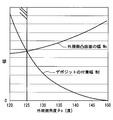
図6は、図2,3の当接部について構成を説明するためのグラフであり、
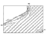
図7は、図4の外周側凸曲面へのデポジットの付着原理について説明するための模式図であり、
図8は、図4の外周側凸曲面に付着するデポジットの体積成長について説明するための模式図であり、
図9は、図4の外周側凸曲面に付着するデポジットの付着幅について説明するためのグラフであり、
図10は、図2,3の当接部について構成を説明するためのグラフであり、
図11は、図2,3の当接部について構成を説明するためのグラフであり、
図12は、動的面圧と摩耗量との相関について説明するためのグラフであり、
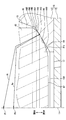
図13は、図4の変形例を示す縦断面図であり、
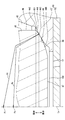
図14は、図4の変形例を示す縦断面図であり、
図15は、図4の変形例を示す縦断面図である。
以下、本開示の一実施形態を図面に基づいて説明する。
図1に示すように、本開示の一実施形態として燃料噴射弁1は、気筒2a内においてガソリンを燃焼させる内燃機関2に、搭載される。燃料噴射弁1は、吸入空気と共に気筒2a内へと吸入される燃料を、当該吸入空気の流通する吸気ポート2bへと噴射する。
(基本構成)
まず、燃料噴射弁1の基本構成を説明する。図2に示すように燃料噴射弁1は、弁ハウジング10、固定コア20、可動コア30、弁部材40、弾性部材50及び駆動部60を備えている。
まず、燃料噴射弁1の基本構成を説明する。図2に示すように燃料噴射弁1は、弁ハウジング10、固定コア20、可動コア30、弁部材40、弾性部材50及び駆動部60を備えている。
弁ハウジング10は、パイプ部材11、弁座部材12及び噴孔部材13等から構成されている。円筒状のパイプ部材11は、第一磁性部110、非磁性部111及び第二磁性部112を、軸方向の開弁側から閉弁側へ向かってこの順に有している。金属磁性体からなる各磁性部110,112と、金属非磁性体からなる非磁性部111とは、例えばレーザ溶接等により同軸上に結合されている。この結合構造により非磁性部111は、第一磁性部110と第二磁性部112との間における磁束の短絡を、遮断している。
第一磁性部110は、燃料ポンプ3(図1参照)から燃料の供給を受ける供給入口14を、形成している。第二磁性部112には、円筒状の金属からなる弁座部材12が同軸上に嵌入固定されている。弁座部材12は、上流側から導かれる燃料を下流側へと流通させるように、燃料通路15をパイプ部材11と共同して形成している。それと共に弁座部材12は、図2~4に示すように燃料通路15に露出する弁座面16を、有している。弁座面16は、燃料通路15の下流側へ向かって縮径する縮径形状として、本実施形態では縮径率が一定のテーパ面状(円錐面状)に形成されている。
有底円筒状の金属からなる噴孔部材13は、第二磁性部112とは反対側において、弁座部材12に同軸上に外嵌固定されている。噴孔部材13は、複数の噴孔17を底部に有している。各噴孔17は、弁座面16よりも下流側において燃料通路15と連通していると共に、吸気ポート2b(図1参照)へ向かって放射状に開口している。
図2に示すように、円筒状の金属磁性体からなる固定コア20は、第一磁性部110及び非磁性部111に同軸上に内嵌固定されている。固定コア20には、円筒状の金属からなるアジャスティングパイプ22が同軸上に圧入固定されている。固定コア20は、上流側の供給入口14から流入した燃料を下流側へ流出させるように、固定通路24をアジャスティングパイプ22と共同して形成している。
円筒状の金属磁性体からなる可動コア30は、非磁性部111及び第二磁性部112内に同軸上に収容されている。可動コア30は、固定コア20よりも閉弁側において、軸方向の両側へと往復移動可能となっている。有底円筒状の金属非磁性体からなる弁部材40は、第二磁性部112内及び弁座部材12内に跨って同軸上に収容されている。図2,3に示すように弁部材40は、可動コア30に閉弁側から嵌入固定されている。これにより弁部材40は、自身の弁中心線Lvに沿う軸方向の両側へ、可動コア30と一体に往復移動可能となっている。弁部材40は、上流側の固定通路24から流出する燃料を下流側の燃料通路15へと導くように、可動通路42を可動コア30と共同して形成している。
弁部材40は、弁座面16よりも上流側において往復移動する当接部44を、閉弁側の底部に有している。図2~4に示すように弁部材40は、全噴孔17よりも上流側において上記縮径形状を呈する弁座面16に対して、当接部44を同軸上に離着座させる。具体的に弁部材40は、開弁側へ移動することで、当接部44を弁座面16から全周に亘って離座させる。その結果、弁部材40が開弁して各噴孔17が燃料通路15と連通するので、それら各噴孔17からは燃料が吸気ポート2b(図1参照)へ噴射される。また一方で弁部材40は、閉弁側へ移動することで、当接部44を弁座面16に全周に亘って着座させる。その結果、弁部材40が閉弁して各噴孔17が燃料通路15との連通を遮断されるので、それら各噴孔17からの燃料噴射が停止する。このように弁部材40は、弁座面16に対する離着座により開閉弁することで、各噴孔17からの燃料噴射を断続可能となっている。
図2に示すように弾性部材50は、金属からなる圧縮コイルスプリングであり、固定コア20及び可動コア30内の各通路24,42に同軸上に収容されている。弾性部材50は、固定コア20内のアジャスティングパイプ22と、可動コア30との間に挟持されている。この挟持構造により弾性部材50は、要素22,30間での圧縮に応じて弾性復原力を発生することで、可動コア30及び弁部材40を閉弁側の弁座面16へと向かって付勢する。即ち、弾性部材50の発生する弾性復原力が、可動コア30及び弁部材40を付勢する付勢力となる。
駆動部60は、ソレノイドコイル61、スプール62、ターミナル63及びコネクタ64等から構成されている。ソレノイドコイル61は、円筒状の樹脂からなるスプール62に金属線材を巻回すことで、形成されている。ソレノイドコイル61は、スプール62を介して磁性部110,112及び非磁性部111に同軸上に外嵌固定されている。金属からなるターミナル63は、樹脂からなるコネクタ64に埋設され、外部の制御回路4(図1参照)と内部のソレノイドコイル61との間を電気接続する。この電気接続によりソレノイドコイル61への通電は、制御回路4により制御可能となっている。
以上の如く構成される燃料噴射弁1の開弁作動では、制御回路4により通電されるソレノイドコイル61が励磁することで、第一磁性部110、固定コア20、可動コア30、及び第二磁性部112に磁束が案内される。その結果、互いに対向するコア20,30間には、可動コア30を開弁側の固定コア20へと向かって吸引するように、磁気吸引力が発生する。すると、可動コア30は、弾性部材50の付勢力に抗した開弁側へ弁部材40と共に駆動されるため、固定コア20に当接して係止される。このとき弁部材40は、当接部44を弁座面16から離座させるので、各噴孔17から燃料が噴射される。
一方、こうした開弁作動後の閉弁作動では、制御回路4により通電を停止されるソレノイドコイル61が消磁するので、コア20,30間の磁気吸引力が消失する。すると、可動コア30は、弾性部材50の付勢力により閉弁側へ弁部材40と共に駆動されるため、当該弁部材40が弁座部材12に当接して係止される。その結果として弁部材40は、当接部44を弁座面16に着座させるので、各噴孔17からの燃料噴射が停止する。また、こうして閉弁した弁部材40は、弾性部材50の付勢力に加えて、可動通路42の燃料から当接部44に作用する燃圧により、弁座面16へと向かって付勢された状態となる。
(弁部材の詳細構成)
次に、弁部材40の詳細構成を図4~6に基づき説明する。尚、図4は、弁部材40の径方向中心に延伸想定される弁中心線Lvを含んで切られる縦断面の一つを、図示している。そこで以下では、弁部材40に関して図4の縦断面を含む任意の縦断面を、単に縦断面というものとする。
次に、弁部材40の詳細構成を図4~6に基づき説明する。尚、図4は、弁部材40の径方向中心に延伸想定される弁中心線Lvを含んで切られる縦断面の一つを、図示している。そこで以下では、弁部材40に関して図4の縦断面を含む任意の縦断面を、単に縦断面というものとする。
図4に示すように弁部材40は、弁中心線Lvを中心とした円筒面状にストレートに延伸する弁外周面46を、当接部44の外周側且つ開弁側に有している。それと共に弁部材40は、当接部44の内周側且つ閉弁側に、凸曲面状又は平面状の先端面47を有している。さらに弁部材40は、部分球面状に湾曲した二種類の凸曲面440,441を、それぞれ当接部44の全周に亘って同軸上に有している。
内周側凸曲面440は、先端面47から外周側且つ開弁側へ連なっている。これにより、内周側凸曲面440よりも下流側に位置する先端面47は、燃料通路15の一部として開弁時に燃料を各噴孔17へと案内する偏平状のサック室150を、弁ハウジング10のうち噴孔部材13との間に形成している。内周側凸曲面440は、所定の曲率半径Riを有し且つ縦断面上では曲率中心位置Piの規定される断面円弧形を、呈している。内周側凸曲面440の曲率中心位置Piは、弁部材40の弁中心線Lv上に規定されている。即ち、内周側凸曲面440は、弁中心線Lvに心合わせされて弁外周面46と同軸上に位置している。
外周側凸曲面441は、弁外周面46から内周側且つ閉弁側へ連なっている。これにより外周側凸曲面441は、弁外周面46から尖鋭状に屈曲する屈曲部442を、全周に亘って形成している。また、外周側凸曲面441は、内周側凸曲面440から内周側且つ開弁側へ連なっている。これにより外周側凸曲面441は、内周側凸曲面440との境界部443を、全周に亘って形成している。ここで境界部443は、弁ハウジング10のうち弁座部材12の弁座面16へと向かって突出する形状を、全周に亘って有している。
外周側凸曲面441は、内周側凸曲面440の曲率半径Riよりも小さな曲率半径Roを有し且つ縦断面上では曲率中心位置Poの規定される断面円弧形を、呈している。外周側凸曲面441の曲率中心位置Poは、弁中心線Lv上のうち内周側凸曲面440の曲率中心位置Piよりも閉弁側に、規定されている。即ち、外周側凸曲面441は、弁中心線Lvに心合わせされて弁外周面46と同軸上に位置している。それ故に、外周側凸曲面441と内周側凸曲面440とがなす突出形状の境界部443も、弁中心線Lvに心合わせされて弁外周面46と同軸上に位置している。したがって、図4にθsを付して示す角度の2倍となるテーパ角度が本実施形態では120度程度のテーパ状弁座面16に対して、境界部443が全周に亘って離着座可能となっている。これにより、テーパ状弁座面16に対して着座した境界部443の調心性及び安定性が高められているのである。
本実施形態の縦断面上では、図5に示すように、外周側凸曲面441に対して境界部443を通って想定される接線を、外周側接線Loと定義する。また図5に示すように、縦断面上において外周側接線Loと弁外周面46とがなす角度を、外周側角度θoと定義する。これら外周側凸曲面441に関する定義下、図6に示すように外周側角度θoは、125度以上且つ130度以下の範囲内、好ましくは125度以上且つ128度以下の範囲内、特に好ましくは125.5度程度に設定される。ここで125度未満の外周側角度θoでは、外周側凸曲面441が弁座面16に近づいて当接し易くなるので、当該当接により閉弁状態の静的面圧が低下するのを抑止するために、125度以上の外周側角度θoが採用される。一方で130度超過の外周側角度θoでは、尖鋭度の増した境界部443が弁座面16と衝突して、図6に示す如く摩耗し易くなるので、当該摩耗を招く動的面圧の過度な増大を抑止するために、130度以下の外周側角度θoが採用される。尚、図6の縦軸に示す摩耗量は、一定燃圧下での所定回数の閉弁作動により弁座面16が摩耗して生じる凹みの軸方向における最大深さにより、表される。
ここで、脂肪酸アミド等のデポジットが外周側凸曲面441に付着する現象と、外周側角度θoとの関係性について、説明する。開弁作動時において外周側凸曲面441と弁座面16との間を流れる燃料流れは、外周側角度θoが小さくなるほど、図7にて矢印で示す如き外周側凸曲面441からの剥離により逆流し易くなる。かかる逆流は、屈曲部442付近での流体力を低下させるため、燃料流れの滞留が生じることで、図8の(a)に示す如きデポジットDが外周側凸曲面441に残留付着すると推定される。こうして残留付着することとなるデポジットDは、開弁作動の繰り返しに従って、図8の(b)に示す如く堆積成長する。尚、図8においてデポジットDは、クロスハッチングを付した部分により示されている。
但し、デポジットDの付着する外周側凸曲面441において、図8に示す屈曲部442からの付着幅Wdは、開弁作動の繰り返し数がある程度増えると、飽和する傾向を示す。これは、デポジットDの堆積成長により屈曲部442付近での外周側角度θoが見かけ上、大きくなることで、燃料流れの滞留が生じ難くなるためと推定される。尚、上述したデポジットDの付着幅Wdは、図8に示す縦断面上でのデポジットDにおいて屈曲部442から最も離間した部分Pdと、屈曲部442との間の距離により、本実施形態では表される。
このようなことから本実施形態では、図8に示す縦断面上での外周側凸曲面441の幅Woとして、屈曲部442と境界部443との間の距離を、デポジットDの付着幅Wdよりも大きく設定する必要がある。これは、仮に外周側凸曲面441の幅WoがデポジットDの付着幅Wdよりも小さいと、境界部443と弁座面16との間では、境界部443が弁座面16と衝突する閉弁作動時にデポジットDが噛み込まれることで、燃料漏れを招いてしまうからである。そこで、屈曲部442及び境界部443の各々について弁中心線Lvからの径方向距離を固定して考えてみると、外周側凸曲面441の幅WoとデポジットDの付着幅Wdとは、それぞれ外周側角度θoとの間に、図10に示す如き相関を現出させる。故に、かかる相関に基づくことで125度以上の外周側角度θoの設定は、上述の如き静的面圧の観点からだけでなく、デポジットDの観点からも、燃料漏れを抑制する上での必要構成であることが分かる。尚、図10の相関は、屈曲部442及び境界部443の各々についての弁中心線Lvからの径方向距離の差を、0.09mm以上確保した場合に、現出するものである。
さらに本実施形態の縦断面上では、図5に示すように、内周側凸曲面440に対して境界部443を通って想定される接線を、内周側接線Liと定義する。また図5に示すように、縦断面上において内周側接線Liと弁外周面46とがなす角度を、内周側角度θiと定義する。これら内周側凸曲面440に関する定義及び先述の外周側凸曲面441に関する定義の下、図7に示すように内周側角度θiと外周側角度θoとの角度差Δθは、4度以上且つ10度以下の範囲内に設定される。ここで4度未満の角度差Δθでは、形状が滑らかになる境界部443と弁座面16との間から、図11に示す如く燃料漏れが生じ易くなるので、当該燃料漏れを招く静的面圧の低下を抑止するために、4度以上の角度差Δθが採用される。一方で10度超過の角度差Δθでは、尖鋭度の増した境界部443が弁座面16と衝突して摩耗し易くなるので、当該摩耗を招く動的面圧の過度な増大を確実に抑止するために、130度以下の外周側角度θoと併せて10度以下の角度差Δθが採用される。尚、図11の縦軸に示す燃料漏れ量は、閉弁状態において境界部443と弁座面16との間から所定時間内に漏れる燃料の体積、即ち体積流量により表される。
ここで、以上の構成により本実施形態が実現する動的面圧につき、説明する。一般に弁部材が公差の範囲で最も傾いて軸ずれした状態下、動的面圧の最大値は、図12に示す如き相関を摩耗量との間に現出させる。そこで本実施形態は、境界部443が弁座面16と衝突する閉弁作動時において境界部443と弁座面16との間に生じる動的面圧を、制限する。即ち本実施形態では、摩耗量が顕著となる1000MPa超えの動的面圧を避けて、1000MPa以下に抑えた動的面圧を実現するように、外周側角度θoが130度以下且つ角度差Δθが10度以下にそれぞれ設定されているのである。尚、図12は、弁部材の傾きが0.1度の場合における動的面圧の最大値と、図6の場合と同様に表される摩耗量との相関を、示している。
(作用効果)
以上説明した燃料噴射弁1の作用効果を、以下に説明する。
以上説明した燃料噴射弁1の作用効果を、以下に説明する。
燃料噴射弁1の弁部材40では、所定の曲率半径Riをもって部分球面状に湾曲した内周側凸曲面440の外周側には、当該内周側凸曲面440よりも小さな曲率半径Roをもって部分球面状に湾曲した外周側凸曲面441が、連なって設けられている。これにより、内周側凸曲面440と外周側凸曲面441との境界部443は、弁座面16へと向かって突出はしているが、尖鋭度の軽減された形状となる。故に、境界部443と弁座面16との間では、境界部443が弁座面16と衝突する閉弁作動時に動的面圧の過度な増大に起因した摩耗を抑止し得る範囲内で、境界部443が弁座面16に着座する閉弁状態での静的面圧を増大させ得る。したがって、閉弁状態において境界部443と弁座面16との間からの燃料漏れを抑制可能である。
また、燃料噴射弁1による弁部材40の縦断面上では、境界部443を通る外周側凸曲面441の外周側接線Loと弁外周面46とがなす外周側角度θoは、125度以上に設定されている。これにより外周側凸曲面441は、下流側へ向かって縮径する弁座面16との間において、境界部443から外周側に向かうほど大きな隙間151(図4参照)を確保し得る。故に、弾性部材50による付勢力の偏り等に起因して弁部材40が弁座面16に対して傾いたとしても、境界部443よりも外周側の外周側凸曲面441が弁座面16と当接して静的面圧が低下するのを、抑止することができる。さらに、125度以上の外周側角度θoによれば、外周側凸曲面441に堆積成長するデポジットDが閉弁作動時に境界部443と弁座面16との間にて噛み込まれるのを、抑止することもできる。しかも燃料噴射弁1によると、弁部材40の縦断面上において外周側角度θoは、130度以下に設定されている。これによれば、外周側凸曲面441と内周側凸曲面440との境界部443に、尖鋭度の軽減された形状を確保し得る。故に、境界部443と弁座面16との間では、動的面圧の過度な増大に起因した摩耗を抑止する機能の確実性を高めることができる。こうしたことから、閉弁状態において境界部443と弁座面16との間からの燃料漏れを抑制することに、貢献可能となる。
さらにまた、燃料噴射弁1による弁部材40の縦断面上では、境界部443を通る内周側凸曲面440の内周側接線Liと弁外周面46とがなす内周側角度θiは、外周側角度θoとの差を4度以上に設定されている。これにより、内周側凸曲面440と外周側凸曲面441との境界部443は、弁座面16へと向かって突出した形状を確実に確保し得る。故に、そうした突出形状の境界部443と弁座面16との間では、静的面圧を増大させる機能の信頼度を向上させることができる。さらに燃料噴射弁1によると、弁部材40の縦断面上において内周側角度θiは、外周側角度θoとの差を10度以下に設定されている。これにより、内周側凸曲面440と外周側凸曲面441との境界部443は、尖鋭度の確実に軽減された形状となる。故に、境界部443と弁座面16との間では、動的面圧の過度な増大に起因した摩耗を抑止する機能の信頼度も、向上させることができる。こうしたことから、閉弁状態において境界部443と弁座面16との間からの燃料漏れを抑制することに、大きく貢献可能となる。
加えて燃料噴射弁1によると、境界部443が弁座面16と衝突する閉弁作動時には、境界部443と弁座面16との間に生じる動的面圧が1000Mpa以下に抑えられることとなる。これによれば、摩耗を抑止する機能を確実に発揮し得るので、閉弁状態において境界部443と弁座面16との間からの燃料漏れを抑制することに、大きく貢献可能となる。
また加えて、燃料噴射弁1による弁部材40の縦断面上において小曲率半径Roの外周側凸曲面441は、弁外周面46から屈曲して連なっているので、下流側へと向かって縮径した弁座面16との間には、外周側に向かうほど大きな隙間151(図4参照)を確保し得る。故に、弾性部材50による付勢力の偏り等に起因して弁部材40が弁座面16に対して傾いたとしても、外周側凸曲面441と弁外周面46とのなす屈曲部442が弁座面16に当接することで閉弁状態の静的面圧が低下するのを、抑止することができる。これによれば、閉弁状態において境界部443と弁座面16との間からの燃料漏れを抑制することに、貢献可能となる。
さらに加えて燃料噴射弁1では、吸気ポート2bへの噴射燃料の比較的低い燃圧により閉弁状態の弁部材40を弁座面16へ向かって押圧する押圧力が低下したとしても、境界部443と弁座面16との間にて動的面圧及び静的面圧に関する機能が発揮され得る。したがって、噴射燃料の燃圧が比較的低圧な構成下でも、閉弁状態での燃料漏れを抑制可能となる。
(他の実施形態)
以上、本開示の一実施形態について説明したが、本開示は、当該実施形態に限定して解釈されるものではなく、本開示の要旨を逸脱しない範囲内において種々の実施形態に適用することができる。
以上、本開示の一実施形態について説明したが、本開示は、当該実施形態に限定して解釈されるものではなく、本開示の要旨を逸脱しない範囲内において種々の実施形態に適用することができる。
具体的に変形例1では、本開示の作用効果が得られる限りにおいて外周側角度θoを、125度以上且つ130度以下の範囲外に設定してもよい。また、変形例2では、本開示の作用効果が得られる限りにおいて角度差Δθを、4度以上且つ10度以下の範囲外に設定してもよい。さらにまた、変形例3では、本開示の作用効果が得られる限りにおいて、境界部443が弁座面16と衝突する閉弁作動時に境界部443と弁座面16との間にて生じる動的面圧を、1000Mpa超えの面圧に設定してもよい。
図13に示すように変形例4では、当接部44のうち外周側凸曲面441の外周側且つ弁外周面46の内周側において、それら面441,46の間を接続する追加面444を形成してもよい。かかる追加面444については、図13に示すように、縦断面上において外周側凸曲面441よりもさらに小さな曲率半径の断面円弧形を呈した部分球面状等の凸曲面状に、形成してもよい。あるいは、追加面444について図示はしないが、例えばテーパ面状等に形成してもよい。尚、図13において外周側凸曲面441と追加面444との境界部は、符号445を付して示されている。
変形例5では、テーパ角度θsが120度以外のテーパ面状に、弁座面16を形成してもよい。また、図14に示すように変形例6では、燃料通路15の下流側へ向かって縮径する縮径率が下流側ほど小さくなる湾曲面状に、弁座面16を形成してもよい。さらにまた、図15に示すように変形例7では、燃料通路15の下流側へ向かって縮径する縮径率が下流側ほど大きくなる湾曲面状に、弁座面16を形成してもよい。
変形例8では、ガソリン式内燃機関の気筒内へ燃料を噴射する燃料噴射弁に、本開示を適用してもよい。また、変形例9では、ディーゼル式内燃機関の気筒内へ燃料を噴射する燃料噴射弁に、本開示を適用してもよい。
Claims (6)
- 内燃機関(2)へ燃料を噴射する噴孔(17)、並びに前記噴孔よりも上流側において下流側へ向かって縮径した弁座面(16)を、有する弁ハウジング(10)と、
前記弁ハウジング内に収容されており、前記弁座面に対して同軸上に離着座することにより、開閉弁して前記噴孔からの燃料噴射を断続させる弁部材(40)と、
前記弁部材を前記弁座面へ向かって付勢している弾性部材(50)と、を備えた燃料噴射弁(1)であって、
前記弁部材は、
所定の曲率半径(Ri)をもって部分球面状に湾曲した内周側凸曲面(440)と、
前記内周側凸曲面の外周側に連なって設けられており、前記内周側凸曲面よりも小さな曲率半径(Ro)をもって部分球面状に湾曲した外周側凸曲面(441)と、を有し、
前記内周側凸曲面と前記外周側凸曲面との境界部(443)は、前記弁座面へ向かって離着座可能に突出していることを特徴とする燃料噴射弁。 - 前記弁部材の縦断面上において、前記外周側凸曲面に対して前記境界部を通って想定される外周側接線(Lo)と、
前記弁部材の縦断面上において、前記弁部材の弁外周面(46)と前記外周側接線とがなす外周側角度(θo)とを、定義すると、
前記外周側角度は、125度以上且つ130度以下の範囲内に設定されていることを特徴とする請求項1に記載の燃料噴射弁。 - 前記弁部材の縦断面上において、前記内周側凸曲面に対して前記境界部を通って想定される内周側接線(Li)と、
前記弁部材の縦断面上において、前記弁部材の弁外周面(46)と前記内周側接線とがなす内周側角度(θi)とを、定義すると、
前記内周側角度と前記外周側角度との角度差(Δθ)は、4度以上且つ10度以下の範囲内に設定されていることを特徴とする請求項2に記載の燃料噴射弁。 - 前記境界部が弁座面と衝突する閉弁作動時において前記境界部と前記弁座面との間に生じる動的面圧は、1000Mpa以下に抑えられることを特徴とする請求項1~3のいずれか一項に記載の燃料噴射弁。
- 前記外周側凸曲面は、前記弁部材の弁外周面(46)から屈曲して連なっていることを特徴とする請求項1~4のいずれか一項に記載の燃料噴射弁。
- 前記噴孔は、前記内燃機関の吸気ポート(2b)へ燃料を噴射することを特徴とする請求項1~5のいずれか一項に記載の燃料噴射弁。
Priority Applications (3)
| Application Number | Priority Date | Filing Date | Title |
|---|---|---|---|
| CN201680041141.5A CN107835897B (zh) | 2015-07-14 | 2016-05-25 | 燃料喷射阀 |
| US15/742,066 US10648440B2 (en) | 2015-07-14 | 2016-05-25 | Fuel injection valve |
| DE112016003154.8T DE112016003154T5 (de) | 2015-07-14 | 2016-05-25 | Kraftstoffeinspritzventil |
Applications Claiming Priority (4)
| Application Number | Priority Date | Filing Date | Title |
|---|---|---|---|
| JP2015-140771 | 2015-07-14 | ||
| JP2015140771 | 2015-07-14 | ||
| JP2016-037257 | 2016-02-29 | ||
| JP2016037257A JP6256495B2 (ja) | 2015-07-14 | 2016-02-29 | 燃料噴射弁 |
Publications (1)
| Publication Number | Publication Date |
|---|---|
| WO2017010034A1 true WO2017010034A1 (ja) | 2017-01-19 |
Family
ID=57757165
Family Applications (1)
| Application Number | Title | Priority Date | Filing Date |
|---|---|---|---|
| PCT/JP2016/002528 Ceased WO2017010034A1 (ja) | 2015-07-14 | 2016-05-25 | 燃料噴射弁 |
Country Status (1)
| Country | Link |
|---|---|
| WO (1) | WO2017010034A1 (ja) |
Cited By (1)
| Publication number | Priority date | Publication date | Assignee | Title |
|---|---|---|---|---|
| CN113294274A (zh) * | 2020-02-06 | 2021-08-24 | 株式会社京浜 | 电磁式燃料喷射阀 |
Citations (4)
| Publication number | Priority date | Publication date | Assignee | Title |
|---|---|---|---|---|
| JPS5970079U (ja) * | 1982-11-01 | 1984-05-12 | 愛三工業株式会社 | 電磁燃料噴射器 |
| JP2002500308A (ja) * | 1997-12-23 | 2002-01-08 | シーメンス オートモーティヴ コーポレイション | 加圧渦流型燃料噴射器の平頭ニードル |
| JP2003003934A (ja) * | 2001-06-20 | 2003-01-08 | Denso Corp | 燃料噴射弁 |
| JP2009150358A (ja) * | 2007-12-21 | 2009-07-09 | Denso Corp | 燃料噴射弁 |
-
2016
- 2016-05-25 WO PCT/JP2016/002528 patent/WO2017010034A1/ja not_active Ceased
Patent Citations (4)
| Publication number | Priority date | Publication date | Assignee | Title |
|---|---|---|---|---|
| JPS5970079U (ja) * | 1982-11-01 | 1984-05-12 | 愛三工業株式会社 | 電磁燃料噴射器 |
| JP2002500308A (ja) * | 1997-12-23 | 2002-01-08 | シーメンス オートモーティヴ コーポレイション | 加圧渦流型燃料噴射器の平頭ニードル |
| JP2003003934A (ja) * | 2001-06-20 | 2003-01-08 | Denso Corp | 燃料噴射弁 |
| JP2009150358A (ja) * | 2007-12-21 | 2009-07-09 | Denso Corp | 燃料噴射弁 |
Cited By (1)
| Publication number | Priority date | Publication date | Assignee | Title |
|---|---|---|---|---|
| CN113294274A (zh) * | 2020-02-06 | 2021-08-24 | 株式会社京浜 | 电磁式燃料喷射阀 |
Similar Documents
| Publication | Publication Date | Title |
|---|---|---|
| US9297471B2 (en) | Solenoid valve | |
| JP5623784B2 (ja) | 電磁式燃料噴射弁 | |
| US9291135B2 (en) | Electromagnetic fuel injection valve | |
| US9303608B2 (en) | Fuel injector | |
| CN102369350B (zh) | 燃料喷射阀 | |
| JP5262972B2 (ja) | 燃料噴射弁 | |
| JP3819906B2 (ja) | 電磁式燃料噴射弁およびその製造方法 | |
| JP2010014088A (ja) | 電磁式燃料噴射弁 | |
| JP2010014088A5 (ja) | ||
| JP6205482B2 (ja) | 電磁式弁 | |
| CN104912709B (zh) | 燃料喷射阀 | |
| JP6256495B2 (ja) | 燃料噴射弁 | |
| JP4782804B2 (ja) | 燃料噴射弁 | |
| JP2015025406A (ja) | 燃料噴射弁 | |
| WO2017010034A1 (ja) | 燃料噴射弁 | |
| JP6354519B2 (ja) | 燃料噴射弁 | |
| JP3932967B2 (ja) | 燃料噴射装置 | |
| US20200102922A1 (en) | Fuel injection valve | |
| JPWO2015068534A1 (ja) | 燃料噴射弁 | |
| JP6658019B2 (ja) | 燃料噴射弁 | |
| JP2011127486A (ja) | 燃料噴射弁 | |
| JP2012097704A (ja) | 燃料噴射弁 | |
| JP4305858B2 (ja) | 燃料噴射弁 | |
| CN118510987A (zh) | 电磁式燃料喷射阀 | |
| WO2023233661A1 (ja) | 気体燃料噴射弁 |
Legal Events
| Date | Code | Title | Description |
|---|---|---|---|
| 121 | Ep: the epo has been informed by wipo that ep was designated in this application |
Ref document number: 16824020 Country of ref document: EP Kind code of ref document: A1 |
|
| WWE | Wipo information: entry into national phase |
Ref document number: 112016003154 Country of ref document: DE |
|
| 122 | Ep: pct application non-entry in european phase |
Ref document number: 16824020 Country of ref document: EP Kind code of ref document: A1 |