WO2017006733A1 - ディスクブレーキ及びディスクブレーキの製造方法 - Google Patents
ディスクブレーキ及びディスクブレーキの製造方法 Download PDFInfo
- Publication number
- WO2017006733A1 WO2017006733A1 PCT/JP2016/067905 JP2016067905W WO2017006733A1 WO 2017006733 A1 WO2017006733 A1 WO 2017006733A1 JP 2016067905 W JP2016067905 W JP 2016067905W WO 2017006733 A1 WO2017006733 A1 WO 2017006733A1
- Authority
- WO
- WIPO (PCT)
- Prior art keywords
- pair
- rotor
- carrier
- disc brake
- pin
- Prior art date
- Legal status (The legal status is an assumption and is not a legal conclusion. Google has not performed a legal analysis and makes no representation as to the accuracy of the status listed.)
- Ceased
Links
Images



Classifications
-
- F—MECHANICAL ENGINEERING; LIGHTING; HEATING; WEAPONS; BLASTING
- F16—ENGINEERING ELEMENTS AND UNITS; GENERAL MEASURES FOR PRODUCING AND MAINTAINING EFFECTIVE FUNCTIONING OF MACHINES OR INSTALLATIONS; THERMAL INSULATION IN GENERAL
- F16D—COUPLINGS FOR TRANSMITTING ROTATION; CLUTCHES; BRAKES
- F16D65/00—Parts or details
- F16D65/02—Braking members; Mounting thereof
-
- F—MECHANICAL ENGINEERING; LIGHTING; HEATING; WEAPONS; BLASTING
- F16—ENGINEERING ELEMENTS AND UNITS; GENERAL MEASURES FOR PRODUCING AND MAINTAINING EFFECTIVE FUNCTIONING OF MACHINES OR INSTALLATIONS; THERMAL INSULATION IN GENERAL
- F16D—COUPLINGS FOR TRANSMITTING ROTATION; CLUTCHES; BRAKES
- F16D55/00—Brakes with substantially-radial braking surfaces pressed together in axial direction, e.g. disc brakes
- F16D55/02—Brakes with substantially-radial braking surfaces pressed together in axial direction, e.g. disc brakes with axially-movable discs or pads pressed against axially-located rotating members
- F16D55/22—Brakes with substantially-radial braking surfaces pressed together in axial direction, e.g. disc brakes with axially-movable discs or pads pressed against axially-located rotating members by clamping an axially-located rotating disc between movable braking members, e.g. movable brake discs or brake pads
- F16D55/224—Brakes with substantially-radial braking surfaces pressed together in axial direction, e.g. disc brakes with axially-movable discs or pads pressed against axially-located rotating members by clamping an axially-located rotating disc between movable braking members, e.g. movable brake discs or brake pads with a common actuating member for the braking members
- F16D55/225—Brakes with substantially-radial braking surfaces pressed together in axial direction, e.g. disc brakes with axially-movable discs or pads pressed against axially-located rotating members by clamping an axially-located rotating disc between movable braking members, e.g. movable brake discs or brake pads with a common actuating member for the braking members the braking members being brake pads
- F16D55/226—Brakes with substantially-radial braking surfaces pressed together in axial direction, e.g. disc brakes with axially-movable discs or pads pressed against axially-located rotating members by clamping an axially-located rotating disc between movable braking members, e.g. movable brake discs or brake pads with a common actuating member for the braking members the braking members being brake pads in which the common actuating member is moved axially, e.g. floating caliper disc brakes
- F16D55/2265—Brakes with substantially-radial braking surfaces pressed together in axial direction, e.g. disc brakes with axially-movable discs or pads pressed against axially-located rotating members by clamping an axially-located rotating disc between movable braking members, e.g. movable brake discs or brake pads with a common actuating member for the braking members the braking members being brake pads in which the common actuating member is moved axially, e.g. floating caliper disc brakes the axial movement being guided by one or more pins engaging bores in the brake support or the brake housing
- F16D55/227—Brakes with substantially-radial braking surfaces pressed together in axial direction, e.g. disc brakes with axially-movable discs or pads pressed against axially-located rotating members by clamping an axially-located rotating disc between movable braking members, e.g. movable brake discs or brake pads with a common actuating member for the braking members the braking members being brake pads in which the common actuating member is moved axially, e.g. floating caliper disc brakes the axial movement being guided by one or more pins engaging bores in the brake support or the brake housing by two or more pins
-
- B—PERFORMING OPERATIONS; TRANSPORTING
- B22—CASTING; POWDER METALLURGY
- B22C—FOUNDRY MOULDING
- B22C9/00—Moulds or cores; Moulding processes
- B22C9/22—Moulds for peculiarly-shaped castings
-
- F—MECHANICAL ENGINEERING; LIGHTING; HEATING; WEAPONS; BLASTING
- F16—ENGINEERING ELEMENTS AND UNITS; GENERAL MEASURES FOR PRODUCING AND MAINTAINING EFFECTIVE FUNCTIONING OF MACHINES OR INSTALLATIONS; THERMAL INSULATION IN GENERAL
- F16D—COUPLINGS FOR TRANSMITTING ROTATION; CLUTCHES; BRAKES
- F16D55/00—Brakes with substantially-radial braking surfaces pressed together in axial direction, e.g. disc brakes
- F16D55/02—Brakes with substantially-radial braking surfaces pressed together in axial direction, e.g. disc brakes with axially-movable discs or pads pressed against axially-located rotating members
- F16D55/22—Brakes with substantially-radial braking surfaces pressed together in axial direction, e.g. disc brakes with axially-movable discs or pads pressed against axially-located rotating members by clamping an axially-located rotating disc between movable braking members, e.g. movable brake discs or brake pads
- F16D55/224—Brakes with substantially-radial braking surfaces pressed together in axial direction, e.g. disc brakes with axially-movable discs or pads pressed against axially-located rotating members by clamping an axially-located rotating disc between movable braking members, e.g. movable brake discs or brake pads with a common actuating member for the braking members
- F16D55/225—Brakes with substantially-radial braking surfaces pressed together in axial direction, e.g. disc brakes with axially-movable discs or pads pressed against axially-located rotating members by clamping an axially-located rotating disc between movable braking members, e.g. movable brake discs or brake pads with a common actuating member for the braking members the braking members being brake pads
- F16D55/226—Brakes with substantially-radial braking surfaces pressed together in axial direction, e.g. disc brakes with axially-movable discs or pads pressed against axially-located rotating members by clamping an axially-located rotating disc between movable braking members, e.g. movable brake discs or brake pads with a common actuating member for the braking members the braking members being brake pads in which the common actuating member is moved axially, e.g. floating caliper disc brakes
- F16D55/2265—Brakes with substantially-radial braking surfaces pressed together in axial direction, e.g. disc brakes with axially-movable discs or pads pressed against axially-located rotating members by clamping an axially-located rotating disc between movable braking members, e.g. movable brake discs or brake pads with a common actuating member for the braking members the braking members being brake pads in which the common actuating member is moved axially, e.g. floating caliper disc brakes the axial movement being guided by one or more pins engaging bores in the brake support or the brake housing
-
- F—MECHANICAL ENGINEERING; LIGHTING; HEATING; WEAPONS; BLASTING
- F16—ENGINEERING ELEMENTS AND UNITS; GENERAL MEASURES FOR PRODUCING AND MAINTAINING EFFECTIVE FUNCTIONING OF MACHINES OR INSTALLATIONS; THERMAL INSULATION IN GENERAL
- F16D—COUPLINGS FOR TRANSMITTING ROTATION; CLUTCHES; BRAKES
- F16D65/00—Parts or details
- F16D65/005—Components of axially engaging brakes not otherwise provided for
- F16D65/0056—Brake supports
-
- F—MECHANICAL ENGINEERING; LIGHTING; HEATING; WEAPONS; BLASTING
- F16—ENGINEERING ELEMENTS AND UNITS; GENERAL MEASURES FOR PRODUCING AND MAINTAINING EFFECTIVE FUNCTIONING OF MACHINES OR INSTALLATIONS; THERMAL INSULATION IN GENERAL
- F16D—COUPLINGS FOR TRANSMITTING ROTATION; CLUTCHES; BRAKES
- F16D65/00—Parts or details
- F16D65/005—Components of axially engaging brakes not otherwise provided for
- F16D65/0068—Brake calipers
-
- F—MECHANICAL ENGINEERING; LIGHTING; HEATING; WEAPONS; BLASTING
- F16—ENGINEERING ELEMENTS AND UNITS; GENERAL MEASURES FOR PRODUCING AND MAINTAINING EFFECTIVE FUNCTIONING OF MACHINES OR INSTALLATIONS; THERMAL INSULATION IN GENERAL
- F16D—COUPLINGS FOR TRANSMITTING ROTATION; CLUTCHES; BRAKES
- F16D65/00—Parts or details
- F16D65/02—Braking members; Mounting thereof
- F16D65/04—Bands, shoes or pads; Pivots or supporting members therefor
- F16D65/092—Bands, shoes or pads; Pivots or supporting members therefor for axially-engaging brakes, e.g. disc brakes
- F16D65/095—Pivots or supporting members therefor
-
- F—MECHANICAL ENGINEERING; LIGHTING; HEATING; WEAPONS; BLASTING
- F16—ENGINEERING ELEMENTS AND UNITS; GENERAL MEASURES FOR PRODUCING AND MAINTAINING EFFECTIVE FUNCTIONING OF MACHINES OR INSTALLATIONS; THERMAL INSULATION IN GENERAL
- F16D—COUPLINGS FOR TRANSMITTING ROTATION; CLUTCHES; BRAKES
- F16D65/00—Parts or details
- F16D65/14—Actuating mechanisms for brakes; Means for initiating operation at a predetermined position
- F16D65/16—Actuating mechanisms for brakes; Means for initiating operation at a predetermined position arranged in or on the brake
- F16D65/18—Actuating mechanisms for brakes; Means for initiating operation at a predetermined position arranged in or on the brake adapted for drawing members together, e.g. for disc brakes
-
- F—MECHANICAL ENGINEERING; LIGHTING; HEATING; WEAPONS; BLASTING
- F16—ENGINEERING ELEMENTS AND UNITS; GENERAL MEASURES FOR PRODUCING AND MAINTAINING EFFECTIVE FUNCTIONING OF MACHINES OR INSTALLATIONS; THERMAL INSULATION IN GENERAL
- F16D—COUPLINGS FOR TRANSMITTING ROTATION; CLUTCHES; BRAKES
- F16D55/00—Brakes with substantially-radial braking surfaces pressed together in axial direction, e.g. disc brakes
- F16D2055/0004—Parts or details of disc brakes
- F16D2055/0008—Brake supports
-
- F—MECHANICAL ENGINEERING; LIGHTING; HEATING; WEAPONS; BLASTING
- F16—ENGINEERING ELEMENTS AND UNITS; GENERAL MEASURES FOR PRODUCING AND MAINTAINING EFFECTIVE FUNCTIONING OF MACHINES OR INSTALLATIONS; THERMAL INSULATION IN GENERAL
- F16D—COUPLINGS FOR TRANSMITTING ROTATION; CLUTCHES; BRAKES
- F16D55/00—Brakes with substantially-radial braking surfaces pressed together in axial direction, e.g. disc brakes
- F16D2055/0004—Parts or details of disc brakes
- F16D2055/0016—Brake calipers
-
- F—MECHANICAL ENGINEERING; LIGHTING; HEATING; WEAPONS; BLASTING
- F16—ENGINEERING ELEMENTS AND UNITS; GENERAL MEASURES FOR PRODUCING AND MAINTAINING EFFECTIVE FUNCTIONING OF MACHINES OR INSTALLATIONS; THERMAL INSULATION IN GENERAL
- F16D—COUPLINGS FOR TRANSMITTING ROTATION; CLUTCHES; BRAKES
- F16D2250/00—Manufacturing; Assembly
- F16D2250/0007—Casting
-
- F—MECHANICAL ENGINEERING; LIGHTING; HEATING; WEAPONS; BLASTING
- F16—ENGINEERING ELEMENTS AND UNITS; GENERAL MEASURES FOR PRODUCING AND MAINTAINING EFFECTIVE FUNCTIONING OF MACHINES OR INSTALLATIONS; THERMAL INSULATION IN GENERAL
- F16D—COUPLINGS FOR TRANSMITTING ROTATION; CLUTCHES; BRAKES
- F16D2250/00—Manufacturing; Assembly
- F16D2250/0084—Assembly or disassembly
-
- F—MECHANICAL ENGINEERING; LIGHTING; HEATING; WEAPONS; BLASTING
- F16—ENGINEERING ELEMENTS AND UNITS; GENERAL MEASURES FOR PRODUCING AND MAINTAINING EFFECTIVE FUNCTIONING OF MACHINES OR INSTALLATIONS; THERMAL INSULATION IN GENERAL
- F16D—COUPLINGS FOR TRANSMITTING ROTATION; CLUTCHES; BRAKES
- F16D55/00—Brakes with substantially-radial braking surfaces pressed together in axial direction, e.g. disc brakes
- F16D55/02—Brakes with substantially-radial braking surfaces pressed together in axial direction, e.g. disc brakes with axially-movable discs or pads pressed against axially-located rotating members
- F16D55/22—Brakes with substantially-radial braking surfaces pressed together in axial direction, e.g. disc brakes with axially-movable discs or pads pressed against axially-located rotating members by clamping an axially-located rotating disc between movable braking members, e.g. movable brake discs or brake pads
- F16D55/224—Brakes with substantially-radial braking surfaces pressed together in axial direction, e.g. disc brakes with axially-movable discs or pads pressed against axially-located rotating members by clamping an axially-located rotating disc between movable braking members, e.g. movable brake discs or brake pads with a common actuating member for the braking members
- F16D55/225—Brakes with substantially-radial braking surfaces pressed together in axial direction, e.g. disc brakes with axially-movable discs or pads pressed against axially-located rotating members by clamping an axially-located rotating disc between movable braking members, e.g. movable brake discs or brake pads with a common actuating member for the braking members the braking members being brake pads
- F16D55/226—Brakes with substantially-radial braking surfaces pressed together in axial direction, e.g. disc brakes with axially-movable discs or pads pressed against axially-located rotating members by clamping an axially-located rotating disc between movable braking members, e.g. movable brake discs or brake pads with a common actuating member for the braking members the braking members being brake pads in which the common actuating member is moved axially, e.g. floating caliper disc brakes
- F16D55/2265—Brakes with substantially-radial braking surfaces pressed together in axial direction, e.g. disc brakes with axially-movable discs or pads pressed against axially-located rotating members by clamping an axially-located rotating disc between movable braking members, e.g. movable brake discs or brake pads with a common actuating member for the braking members the braking members being brake pads in which the common actuating member is moved axially, e.g. floating caliper disc brakes the axial movement being guided by one or more pins engaging bores in the brake support or the brake housing
- F16D55/22655—Constructional details of guide pins
Definitions
- the present invention relates to a disc brake and a manufacturing method thereof.
- the disc brake is provided with an electric motor that drives a piston (see Patent Document 1).
- MGU motor gear unit
- An object of the present invention is to provide a disc brake and a disc brake manufacturing method capable of solving the interference problem between the carrier and the electric motor with a simple structure.
- a disc brake according to an embodiment of the present invention includes a pair of pads disposed on both sides of the rotor in the axial direction of the rotor across the rotor, and a carrier that supports the pair of pads. Includes a beam portion attached to a non-rotating portion of the vehicle, a pair of arm portions extending from both ends of the beam portion in the radial direction of the rotor, and a pair of pin insertions extending from the pair of arm portions across the rotor.
- a recess that opens toward the other of the pair of arm portions is provided on a surface opposite to the rotor.
- the carrier has a line segment extending in a direction perpendicular to a line segment connecting the centers of the pair of pin holes with respect to the mold opening / closing direction. It is molded by a pair of molds in which product cavities corresponding to carriers are formed inside so as to be inclined.
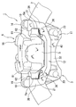
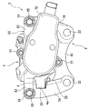
- the external view which looked at the disc brake from the front-back direction of the vehicle The external view which looked at the disc brake from the vehicle outer side (outer side).
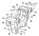
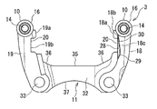
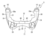
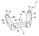
- the perspective view of the product shape carrier. The figure which looked at the product-shaped carrier from the inside of the vehicle.
- the disc brake 1 will be described in detail with reference to FIGS.
- the wheel side with respect to the disc rotor 2 will be referred to as the outer side
- the left and right central portion of the vehicle opposite to the wheels with respect to the disc rotor 2 will be referred to as the inner side.
- the axial direction of the rotation axis of the disk rotor 2 is referred to as a disk axis direction
- the radial direction of the disk rotor 2 is referred to as a disk radial direction
- the rotation direction of the disk rotor 2 is referred to as a disk rotation direction.
- the present disc brake 1 is a caliper floating disc brake, which is a carrier fixed to a disc rotor 2 that rotates with a wheel and a non-rotating portion (not shown) on the vehicle body side. 3, a pair of inner and outer pads 4, 5 disposed on both sides of the disk rotor 2 and supported by the carrier 3, and a pair of slide pins 15, 15 disposed across the disk rotor 2 with respect to the carrier 3 And a caliper 6 supported so as to be movable along the axial direction of the disk rotor 2.
- the carrier 3 includes a pair of pin insertion portions 10 and 10 through which a pair of slide pins 15 and 15 are inserted, and a pair of pins.
- the inner side and outer side support parts 11 and 12 which are integrally connected to the insertion parts 10 and 10 and support the inner and outer pads 4 and 5 independently are provided.
- the pair of pin insertion portions 10 and 10 are arranged at intervals along the disk rotation direction, and both extend along the disk axial direction.
- Each pin insertion portion 10 is formed in a bottomed cylindrical shape having a pin hole 14 through which the slide pin 15 is inserted.
- Each pin insertion portion 10 has an opening side of the pin hole 14 facing the inner side, and a bottom side facing the outer side.
- a cylindrical pin hole boss portion 16 is formed around the pin hole 14 at the inner end of each pin insertion portion 10.
- the outer diameter of the pin hole boss portion 16 is larger than the outer diameter of the pin insertion fitting portion 10.
- the outer side support portion 12 is integrally connected to the outer side of each pin insertion portion 10.
- Inner side support portions 11 are connected to each pin insertion portion 10 with an interval from the outer side support portion 12 to the inner side along the disk axial direction.
- the inner side support portion 11 connects a pair of inner side arm portions 18 and 19 whose one end portions are respectively connected to the pin insertion portions 10 and 10 and the other end portions of the pair of inner side arm portions 18 and 19. And an inner side beam portion 32.
- Each of the inner side arm portions 18 and 19 receives a braking torque transmitted from the inner pad 4 when the vehicle is braked when the vehicle is moving forward or backward.
- one inner side arm portion 18 is formed with first and second facing surfaces 18 a and 18 b facing the other inner side arm portion 19.
- the first facing surface 18a and the second facing surface 18b are formed in a stepped shape (see FIG. 4).
- the second opposing surface 18b is a position retracted from the first opposing surface 18a to the pin insertion portion 10 side in the disk rotation direction, at a position closer to the inner side than the first opposing surface 18a in the disk axial direction, and in the disk radial direction. It is formed in a partial region near the pin insertion portion 10.
- the first facing surface 18a and the second facing surface 18b extend substantially in parallel.
- the other inner side arm portion 19 is formed with first and second facing surfaces 19a and 19b facing the one inner side arm portion 18 (see FIG. 8).
- the first facing surface 19a and the second facing surface 19b are formed in a stepped shape.
- the second opposing surface 19b is a position retracted from the first opposing surface 19a to the pin insertion portion 10 side in the disk rotation direction, at a position on the inner side from the first opposing surface 19a in the disk axial direction, and in the disk radial direction. It is formed in a partial region near the pin insertion portion 10.
- the first opposing surface 19a and the second opposing surface 19b extend substantially in parallel.
- the first and second opposing surfaces 18a, 18b of one inner side arm portion 18 and the first and second opposing surfaces 19a, 19b of the other inner side arm portion 19 are The centers of the pair of pin hole boss portions 16 and 16 (pin holes 14 and 14) are connected so that the distance from the connecting portion with the side beam portion 32 gradually increases (like a reverse C shape).
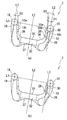
- the line segment L2 extends in an inclined manner with respect to a line segment L2 (hereinafter referred to as a line segment L2) extending in a direction substantially perpendicular to the line segment L1.
- the inclination angle ⁇ 1 of the first and second opposing surfaces 18a and 18b of the one inner side arm 18 with respect to the line segment L2 is the line of the first and second opposing surfaces 19a and 19b of the other inner side arm 19. It is formed smaller than the inclination angle ⁇ 2 with respect to the minute L2.
- Support recesses 20 and 20 extending in the disk axial direction are formed on the first facing surfaces 18a and 19a of the inner side arm portions 18 and 19, respectively.
- the support recesses 20, 20 are formed in a U-shaped cross section.
- the inner pad 4 has the engaging portions 4 a, 4 a protruding from both sides thereof engaged with the supporting recesses 20, 20 of the inner side supporting portion 11, thereby On the other hand, it is supported so as to be movable in the approaching / retreating direction.
- springs 25, 25 are fixed to the support recesses 20, 20 of the inner side arm portions 18, 19 along the inner wall surfaces thereof.
- the springs 25, 25 are arranged between the engaging portions 4 a, 4 a of the inner pad 4 and the support recesses 20, 20 of the inner side arm portions 18, 19. Within each support recess 20, the pin insertion portion 10 is urged radially outward of the disk rotor 2.
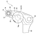
- the electric motor 57 reaches from the second facing surface 18 b of one inner side arm portion 18 to the inner side inner surface 18 c facing the tip of the electric motor 57 (described later).
- a recess 28 is formed to avoid interference with a small-diameter protrusion 74a (described later) of a second housing portion 74 (described later) that accommodates the housing.
- the recess 28 is recessed along the disk axis direction and the disk rotation direction.
- the concave portion 28 is parallel to the line segment L2 and is parallel to the tangent line L3 and through the center of the pin hole 14 (pin hole boss portion 16) rather than the tangent line L3 of one pin hole boss portion 16 (opposite to L2).
- the concave portion 28 is seen from the inner side, the arc-shaped arc-shaped portion 29, and extends from the arc-shaped portion 29 in the tangential direction, and extends toward the second opposing surface 18b of one inner-side arm portion 18. It is formed in a shape having a linear portion 30.
- the arc-shaped portion 29 is formed on the inner side beam portion 32 side.
- the linear portion 30 is inclined at a predetermined inclination angle ⁇ 3 with respect to the line segment L2.
- the inclination angle ⁇ 2 of the first and second opposing surfaces 19a, 19b of the other inner side arm portion 19 with respect to the line segment L2 is set larger than the inclination angle ⁇ 3 of the linear portion 30 with respect to the line segment L2. Note that ⁇ 2 and ⁇ 3 may be substantially the same.
- through holes 33 and 33 are formed at both ends of the inner side beam portion 32 so as to penetrate along the disc axial direction in order to attach the carrier 3 to a non-rotating portion of the vehicle.
- the inner side beam portion 32 is formed so as to gradually increase in width along the direction of the line segment L2 (disk radial direction) from the central portion toward both ends, and the periphery of each through hole 33 is formed to be the largest.
- one surface of the inner side beam portion 32 on the side of the pin insertion portion 10 is formed with a flat surface 35 at the center in the longitudinal direction, and the first and first inner arm portions 18 and 19 from both ends of the flat surface 35.
- the inclined surfaces 36 and 36 extend toward the opposing surfaces 18a, 18b, 19a, and 19b.
- the other surface of the inner beam portion 32 is formed as a concave arc surface 37, and the width around each through hole 33 is Maximum.
- the thickness in the disc axial direction around each through-hole 33 of the inner side beam portion 32 is formed to be substantially the same as the thickness in the disc axial direction of each inner side arm portion 18, 19.
- a portion between the through holes 33 and 33 of the inner side beam portion 32 is formed such that the thickness in the disc axial direction is thinner than the thickness of the inner side arm portions 18 and 19 in the disc axial direction.
- the outer support portion 12 has one end connected to each of the pin insertion portions 10 and 10, respectively.
- a pair of outer side arm portions 38 and 39 and an outer side beam portion 42 connecting the other end portions of the pair of outer side arm portions 38 and 39 are configured.
- the opposing surfaces 38 a and 39 a of the outer side arm portions 38 and 39 are formed continuously from the second opposing surfaces 18 b and 19 b of the inner side arm portions 18 and 19 of the inner side support portion 11.
- the opposing surface 38a of the one outer side arm portion 38 and the opposing surface 39a of the other outer side arm portion 39 are gradually increased in distance from each other from the connecting portion with the outer side beam portion 42 ( As in the case of an inverted letter C), each of them extends with an inclination with respect to the line segment L2.
- the inclination angle ⁇ 1 (see FIG. 9) of the opposing surface 38a of one outer side arm portion 38 with respect to the line segment L2 is the inclination angle ⁇ 2 of the opposing surface 38b of the other outer side arm portion 39 with respect to the line segment L2 (see FIG. 9). Smaller than the reference).
- Each of the outer side arm portions 38 and 39 receives a braking torque transmitted from the outer brake pad 5 when the vehicle is braked when the vehicle is moving forward or backward.
- Support recesses 21 and 21 extending in the disk axial direction are formed on the facing surfaces 38a and 39a of the outer arm portions 38 and 39, respectively.
- Each of the support recesses 21 is formed in a U-shaped cross section.
- the outer pad 5 has support recesses 21, 21 provided on the opposing surfaces 38 a, 39 a of the outer side arm portions 38, 39, with the engaging portions 5 a, 5 a protruding from both sides thereof. And is supported so as to be movable in the approaching / retreating direction with respect to the disk rotor 2.
- springs 26 and 26 are fixed to the support recesses 21 and 21 of the outer arm portions 38 and 39 along the inner wall surfaces thereof.
- the springs 26, 26 are disposed between the engaging portions 5 a, 5 a of the outer pad 5 and the support recesses 21, 21 of the outer side arm portions 38, 39. In FIG. 21, the pin insertion portion 10 is urged radially outward of the disk rotor 2.
- the outer side beam portion 42 is formed in a convex shape toward the center of the disk rotor 2.
- the outer side arm portions 38 and 39 and the outer side beam portion 42 are formed to have substantially the same thickness along the entire disk axial direction.
- the outer side beam portion 42 is formed to have a shorter length along the line segment L2 (disk radial direction) than the inner side beam portion 32.
- the surface on the pin insertion portion 10 side of the outer side beam portion 42 is formed as a flat surface 44, and the flat surface 44 of the outer side beam portion 42 and the flat surface 35 of the inner side beam portion 32 are on the same plane.
- the inner side support part 11 is formed thicker than the outer side support part 12 in the overall thickness along the disk axial direction.
- the carrier 3 including the escape portion is integrally formed by casting without using an undercut processing structure that employs a core, a nest, or the like.
- the carrier 3 is first integrally formed into a shape shown in FIGS. 8 to 10 by a casting apparatus.
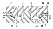
- the casting apparatus to be used is constituted by a pair of mold structures 50 and 51 without providing an undercut processing structure such as a core or a nest (slide core or the like).
- the concave portion 28 (the hatched area) of the present embodiment is exaggerated for easy understanding.
- P. L is a parting line.
- product cavities 52R and 52L corresponding to the right carrier 3 and the left carrier 3 are formed between the pair of molds 50 and 51, respectively.
- the product cavities 52R and 52L corresponding to the carriers are such that the mold opening / closing direction (arrow direction) of the pair of molds 50 and 51 and the extending direction of the linear portion 30 provided in the concave portion 28 of the carrier 3 coincide.
- a line segment L2 of 52R and 52L is formed to be inclined at an inclination angle ⁇ 3 with respect to the mold opening / closing direction of the pair of molds 50 and 51.
- the product cavity 52R for the right is formed such that the line segment L2 is inclined to the right side in the drawing at an inclination angle ⁇ 3 with respect to the mold opening / closing direction of the pair of molds 50 and 51.
- the product cavity 52L for the left is formed such that the line segment L2 is inclined leftward toward the drawing at an inclination angle ⁇ 3 with respect to the mold opening / closing direction of the pair of molds 50 and 51.
- the molten metal inlet 53 into the cavity of the molten metal is provided at a position corresponding to the pin insertion portion 10 portion of each carrier 3 in each of the product cavities 52R and 52L.
- the molten metal flows from the molten metal inlets 53 and 53 and is filled in the product cavities 52R and 52L.
- the pair of molds 50, 51 are opened.
- the inclination angle ⁇ 2 of the first and second opposing surfaces 19a, 19b of the other inner side arm portion 19 with respect to the line segment L2 is equal to the line segment L2 of the linear portion 30 of the recess 28.
- the undercut portion is not formed in the concave portion 28 provided on one inner side arm portion 18 by setting the inclination angle ⁇ 3 to be larger and matching the mold opening / closing direction with the extending direction of the linear portion 30 of the concave portion 28.
- the pair of molds 50 and 51 can be easily released.
- the carrier 3 containing the recessed part 28 is cast-molded.
- each support recessed part 20 and 21 of each inner side and outer side arm part 18,19,38,39 is machined in order to require a dimensional accuracy.
- a caliper body 55 In the caliper 6, a caliper body 55, a piston unit 56, an electric motor 57 arranged so as to be aligned with the caliper body 55, and a housing 58 that houses the piston unit 56 and the electric motor 57 are integrally configured.
- the caliper body 55 includes a cylindrical cylinder portion 60 that opens to face one side of the disk rotor 2, a claw portion 61 that extends from the cylinder portion 60 to the opposite side across the disk rotor 2, and an external portion from the cylinder portion 60.
- a pair of caliper arm portions 62, 62 extending in the direction is integrally formed.
- Slide pins 15 and 15 are fixed to the pair of caliper arm portions 62 and 62 by fixing nuts 65 and 65, respectively.
- the slide pins 15 and 15 are inserted into the pin holes 14 of the pin insertion portions 10 of the carrier 3 so as to be slidable in the axial direction.
- Rubber pin boots 66 and 66 having elastic bellows portions covering the slide pins 15 and 15 are provided between one end portions of the slide pins 15 and 15 and the pin insertion portions 10 and 10 of the carrier 3. ing.
- the cylinder portion 60 is formed with a guide bore 68 into which the piston 70 of the piston unit 56 is slidably fitted.
- the piston unit 56 is disposed in a bottomed cylindrical piston 70, a housing 58, a speed reduction mechanism 71 that reinforces the rotational force from the electric motor 57, and is accommodated in the piston 70, and is supplied from the speed reduction mechanism 71.
- a rotation / linear motion conversion mechanism 72 that converts rotational motion into linear motion, applies thrust to the piston 70, and holds the piston 70 at a braking position is provided.
- the piston 70 is slidably fitted to the guide bore 68 of the caliper main body 55 (cylinder portion 60).
- the inner pad 4 is held by the inner side support portion 11 of the carrier 3 at a position facing the bottom portion of the piston 70.
- the housing 58 covers the outer periphery of the cylinder part 60, and includes a first housing part 73 that houses the speed reduction mechanism 71, and a bottomed cylinder that extends integrally from the first housing part 73 toward the carrier 3 along the axial direction. And a second housing part 74 that houses the electric motor 57.
- the opening 58 a at one end of the housing 58 is airtightly closed by the cover 75.
- a small-diameter projecting portion 74 a projects from one end surface of the second housing portion 74 in the axial direction.
- the tip of the second housing part 74 is directed between the inner surface 18 c of the inner side arm part 18 of the inner side support part 11 constituting the carrier 3 and the second facing surface 18 b.
- the housing 58 is fixed to the cylinder portion 60 of the caliper main body 55 via a fixing portion 77 protruding outward from the outer peripheral portion of the first housing portion 73.
- the first housing portion 73 of the housing 58 is fixed to the cylinder portion 60 of the caliper main body 55 through the fixing portion 77 to constitute the caliper 67.
- the slide pins 15 and 15 are fixed to a pair of caliper arm portions 62 and 62 provided on the caliper main body 55 of the caliper 67 by fixing nuts 65 and 65, respectively.
- the slide pins 15 and 15 are inserted into the pin holes 14 and 14 of the pin insertion portions 10 and 10 of the carrier 3 so as to be slidable in the axial direction.
- the carrier 3 is fixed to the non-rotating portion on the vehicle body side through the through holes 33 and 33 of the inner side support portion 11.
- the second housing portion 74 that houses the electric motor 57 is disposed along the disk axial direction, and the small-diameter protrusion 74a of the second housing supports the inner side of the carrier 3 as shown in FIGS.
- the inner side arm portion 18 of the inner side arm portion 18 of the portion 11 is disposed in the vicinity of the inner side surface 18c, but a concave portion 28 is formed from the second facing surface 18b of the inner side arm portion 18 to the inner surface 18c. Therefore, it is possible to suppress the small-diameter protrusion 74 a of the second housing 58 from interfering with the one inner arm portion 18 of the inner support portion 11.
- a parking brake which is an example of an action for maintaining the stop state of the vehicle
- the electric motor 57 is driven, and the rotational force is converted into the rotation linear motion via the speed reduction mechanism 71 of the piston unit 56. It is transmitted to the mechanism 72 and converted into a straight movement of the piston 70.
- the piston 70 moves forward, the disc rotor 2 is sandwiched between the inner and outer pads 4, 5 to generate a braking force, and the braking position of the piston 70 is held by the rotation / linear motion conversion mechanism 72. As a result, the braking force is maintained and the operation of the parking brake is completed.
- the electric motor 57 is rotationally driven in a release direction in which the piston 70 is separated from the disk rotor 2.
- the speed reduction mechanism 71 is rotationally driven in the release direction to return the piston 70, and the piston 70 is moved back to the original position by the restoring force of the elastic deformation of the piston seal, and the braking force is completely released.
- the carrier 3 employed in the disc brake 1 has the electric motor from the second opposing surface 18b of the one inner side arm portion 18 with the other inner side arm portion 19.
- Recess 28 that avoids interference with small-diameter protrusion 74a (electric motor 57) is formed reaching inner surface 18c on the inner side facing small-diameter protrusion 74a of second housing part 74 that accommodates 57.
- the concave portion 28 is formed in a shape having an arc-shaped portion 29 as viewed from the inner side, and a linear portion 30 extending in a tangential direction from the arc-shaped portion 29 and extending toward the second facing surface 18b. .
- the linear portion 30 extends at an inclination angle ⁇ 3 with respect to the line segment L2, and the inclination angle ⁇ 2 of the first and second opposing surfaces 19a, 19b of the other inner side arm portion 19 with respect to the line segment L2 is the same.
- the inclination angle ⁇ 3 of the linear portion 30 is set larger.
- the carrier 3 can be formed by a pair of molds 50 and 51 not including an undercut processing structure. Specifically, when the product cavity 52R (52L) corresponding to the carrier is formed in the pair of molds 50, 51, the mold opening / closing direction and the direction in which the linear portion 30 of the recess 28 provided in the inner support portion 11 extends. So that the product cavity 52R (52L) is inclined at an inclination angle ⁇ 3 with respect to the mold opening / closing direction.
- the undercut part is not formed in the part of the recessed part 28 provided on the inner side support part 11 (one inner side arm part 18) of the carrier 3 to avoid the interference with the electric motor 57, the recessed part 28 is It becomes possible to integrally mold with a pair of molds 50 and 51 not including an undercut processing structure.
- the shape viewed from the inner side from the second facing surface 18b of the one inner side arm portion 18 of the carrier 3 to the inner side inner surface 18c is an arc-shaped portion 29, and
- the concave portion 28 having a linear portion 30 extending in a tangential direction from the arc-shaped portion 29 and extending toward the second opposing surface 18b is formed.
- the shape of the concave portion 28 viewed from the inner side is the second opposing surface 18b.
- the line segment L2 has an undercut portion in the concave portion 28 with respect to the mold opening / closing direction of the pair of molds 50 and 51. It becomes possible to incline at an inclination angle that is not formed.
- the disc brake includes a pair of pads disposed on both sides of the rotor in the axial direction of the rotor across the rotor, and a carrier that supports the pair of pads, A beam portion attached to a non-rotating portion of the vehicle, a pair of arm portions extending from both ends of the beam portion in the radial direction of the rotor, and a pair of pin insertions extending from the pair of arm portions across the rotor And a pair of pin holes formed along the rotor axial direction, and pin hole bosses provided around the pin holes, respectively, at the end portions of the pin insertion portions.
- a recess opening toward the other of the pair of arm portions is formed on a surface opposite to the disk.
- the concave portion is perpendicular to a line segment connecting the centers of the pair of pin holes in one of the pair of arm portions.
- the pin hole boss is formed by being casted in a direction from a line in contact with the other side end of the pin hole boss part to a line side parallel to the contact line and passing through the center of the pin hole on the one side.
- the other side of the carrier that is disposed on the opposite side to the center along the rotor axial direction of the pair of arms.
- the carrier is molded by a pair of molds not including an undercut treatment structure.
- the concave portion is formed on the inner side from the surface of the one arm portion facing the other arm portion. It is formed in the range reaching the inner surface.
- a sixth aspect includes a pair of pads disposed on both sides of the rotor in the axial direction across the rotor, and a carrier that supports the pair of pads, and the carrier is attached to a non-rotating portion of the vehicle.
- One of the pair of pin holes formed at the end portions of the fitting portions and drilled along the rotor axial direction, the pin hole boss portions provided around the pin holes, and the pair of arm portions The pin on one side parallel to the contact line and perpendicular to the line segment connecting the centers of the pair of pin holes, rather than the line contacting the other end of the pin hole boss on the one side
- a rake manufacturing method wherein the carrier has an inner portion corresponding to the carrier so that a line extending in a direction perpendicular to a line connecting the centers of the pair of pin holes is inclined with respect to a mold opening / closing direction. It is formed by a pair of molds in which product cavities are formed.
Landscapes
- Engineering & Computer Science (AREA)
- General Engineering & Computer Science (AREA)
- Mechanical Engineering (AREA)
- Braking Arrangements (AREA)
- Braking Systems And Boosters (AREA)
- Molds, Cores, And Manufacturing Methods Thereof (AREA)
Abstract
Description
図4~図6に示すように(適宜、図1~図3も参照)、キャリア3は、一対のスライドピン15、15が挿通される一対のピン挿嵌部10、10と、一対のピン挿嵌部10、10に一体的に連結され、インナ及びアウタパッド4、5をそれぞれ独立して支持するインナ側及びアウタ側支持部11、12とを備えている。一対のピン挿嵌部10、10は、ディスク回転方向に沿って間隔を置いて配置され、共にディスク軸方向に沿ってそれぞれ延びている。各ピン挿嵌部10は、内部にスライドピン15が挿通されるピン穴14を有する有底円筒状に形成される。各ピン挿嵌部10はそのピン穴14の開口側がインナ側を向き、その底部側がアウタ側を向く。各ピン挿嵌部10のインナ側端部のピン穴14の周りには、円筒状のピン穴ボス部16が形成される。ピン穴ボス部16の外径は、ピン挿嵌合部10の外径よりも大径である。各ピン挿嵌部10のアウタ側にアウタ側支持部12が一体的に連結される。各ピン挿嵌部10の、アウタ側支持部12からディスク軸方向に沿ってインナ側に間隔を置いてインナ側支持部11が連結される。
なお、インナ側支持部11が、アウタ側支持部12よりも、そのディスク軸方向に沿う全体的な厚みが厚く形成される。
これに対して、キャリア3に電動モータ57との干渉を避ける逃げ部を形成することが考えられる。しかし、該逃げ部を後工程の機械加工で形成すると、コスト高となる。また、鋳型構造に中子や入子等を採用してアンダーカット処理により逃げ部を一体成形する場合でも、鋳型構造が複雑化して、コスト高となる。
キャリパ6は、キャリパ本体55と、ピストンユニット56と、キャリパ本体55と並ぶように配置される電動モータ57と、ピストンユニット56及び電動モータ57を収容するハウジング58とが一体的に構成される。
キャリパ本体55には、ディスクロータ2の一側に対向して開口する円筒状のシリンダ部60と、シリンダ部60からディスクロータ2を跨いで反対側へ延びる爪部61と、シリンダ部60から外方に延びる一対のキャリパ腕部62、62が一体的に形成される。一対のキャリパ腕部62、62にはそれぞれスライドピン15、15が各固定ナット65、65により固定される。各スライドピン15、15が、キャリア3の各ピン挿嵌部10のピン穴14に軸方向に摺動自在に挿通される。各スライドピン15、15の一端部とキャリア3のピン挿嵌部10、10との間には、スライドピン15、15を覆う伸縮自在な蛇腹部を有するゴム製のピンブーツ66、66が設けられている。シリンダ部60には、ピストンユニット56のピストン70が摺動可能に嵌合される案内ボア68が形成されている。
まず、ブレーキペダル(図示略)の操作による通常の液圧ブレーキとしてのディスクブレーキ1の制動時における作用を説明する。
運転者によりブレーキペダルが踏み込まれると、ブレーキペダルの踏力に応じた液圧がマスタシリンダから液圧回路(共に図示略)を経てキャリパ本体55のシリンダ部60内の液圧室に供給される。これにより、ピストン70がピストンシール(図示略)を弾性変形させながら非制動時の原位置から前進(図11の左方向に移動)してインナパッド4をディスクロータ2に押し付ける。そして、キャリパ本体55は、ピストン70の押圧力の反力によりキャリア3に対して図11における右方向に移動して、爪部61に取り付けられたアウタパッド5をディスクロータ2に押し付ける。この結果、ディスクロータ2が一対のインナ及びアウタパッド4、5により挟みつけられて摩擦力が発生し、ひいては、車両の制動力が発生する。
これにより、キャリア3のインナ側支持部11(一方のインナ側腕部18)に設けた、電動モータ57との干渉を避ける凹部28の部位にアンダーカット部が成形されないので、該凹部28を、アンダーカット処理構造を含まない一対の鋳型50、51によって一体成形することが可能になる。
第1の態様としては、ディスクブレーキは、ロータを挟んで該ロータの軸方向における該ロータの両側に配置される一対のパッドと、前記一対のパッドを支持するキャリアと、を備え、該キャリアは、車両の非回転部に取り付けられるビーム部と、該ビーム部の両端部から前記ロータの径方向に延びる一対の腕部と、該一対の腕部から前記ロータを跨いで延びる一対のピン挿嵌部と、該各ピン挿嵌部の端部にそれぞれ形成され、前記ロータ軸方向に沿って設けられた一対のピン穴と、該ピン穴の周囲に設けられるピン穴ボス部と、を備え、前記一対の腕部のうちの一方において、ディスクと反対側の面に、前記一対の腕部のうちの他方に向かって開口する凹部が形成されている。
第2の態様としては、第1の態様において、前記凹部は、前記一対の腕部のうちの一方において、前記一対のピン穴の中心を結んだ線分に対して垂直となる、該一方側のピン穴ボス部の他方側端部と接する線よりも、該接する線に平行かつ該一方側のピン穴の中心を通る線側へ向かう方向に、鋳抜かれて形成される。
第3の態様としては、第1の態様または第2の態様のいずれかにおいて、前記一対の腕部に対して、前記キャリアの、ロータ軸方向に沿う中心とは反対側に配置される他方側の一対の腕部を備え、前記一対の腕部と、前記他方側の一対の腕部との距離は、前記ビーム部から離れるに従い大きくなっている。
第4の態様としては、第2の態様において、第1の態様乃至第3の態様のいずれかにおいて、前記キャリアは、アンダーカット処理構造を含まない一対の鋳型で成形される。
第5の態様としては、第2の態様において、第1の態様乃至第4の態様のいずれかにおいて、前記凹部は、前記一方の腕部の、他方の腕部との対向面からインナ側の内面に至る範囲に形成される。
第6の態様としては、ロータを挟んで該ロータ軸方向両側に配置される一対のパッドと、前記一対のパッドを支持するキャリアと、を備え、該キャリアは、 車両の非回転部に取り付けられるビーム部と、該ビーム部の両端部から前記ロータの径方向に延びて形成される一対の腕部と、該一対の腕部から前記ロータを跨いで延びるピン挿嵌部と、該各ピン挿嵌部の端部にそれぞれ形成され、ロータ軸方向に沿って穿設される一対のピン穴と、該ピン穴の周囲に設けられるピン穴ボス部と、前記一対の腕部のうちの一方において、前記一対のピン穴の中心を結んだ線分に対して垂直となる、該一方側のピン穴ボス部の他方側端部と接する線よりも、該接する線に平行かつ該一方側のピン穴の中心を通る線側へ向かう方向に凹部を備えるディスクブレーキの製造方法であって、前記キャリアは、前記一対のピン穴の中心を結んだ線分に対して垂直方向に延びる線分が型開閉方向に対して傾斜するように、内部にキャリア相当の製品キャビティを形成した一対の鋳型により成形される。
Claims (6)
- ディスクブレーキであって、該ディスクブレーキは、
ロータを挟んで該ロータの軸方向における該ロータの両側に配置される一対のパッドと、
前記一対のパッドを支持するキャリアと、を備え、
該キャリアは、
車両の非回転部に取り付けられるビーム部と、
該ビーム部の両端部から前記ロータの径方向に延びる一対の腕部と、
該一対の腕部から前記ロータを跨いで延びる一対のピン挿嵌部と、
該各ピン挿嵌部の端部にそれぞれ形成され、前記ロータ軸方向に沿って設けられた一対のピン穴と、
該ピン穴の周囲に設けられるピン穴ボス部と、を備え、
前記一対の腕部のうちの一方において、前記ロータと反対側の面に、前記一対の腕部のうちの他方に向かって開口する凹部が形成された、ディスクブレーキ。 - 前記凹部は、前記一対の腕部のうちの一方において、前記一対のピン穴の中心を結んだ線分に対して垂直となる、該一方側のピン穴ボス部の他方側端部と接する線よりも、該接する線に平行かつ該一方側のピン穴の中心を通る線側へ向かう方向に、鋳抜かれて形成された、請求項1記載のディスクブレーキ。
- 前記一対の腕部に対して、前記キャリアの、ロータ軸方向に沿う中心とは反対側に配置される他方側の一対の腕部を備え、
前記一対の腕部と、前記他方側の一対の腕部との距離は、前記ビーム部から離れるに従い大きくなっている、請求項1又は2に記載のディスクブレーキ。 - 前記キャリアは、アンダーカット処理構造を含まない一対の鋳型で成形される、請求項1乃至3のいずれかに記載のディスクブレーキ。
- 前記凹部は、前記一方の腕部の、他方の腕部との対向面からインナ側の内面に至る範囲に形成される、請求項1乃至4のいずれかに記載のディスクブレーキ。
- ロータを挟んで該ロータ軸方向両側に配置される一対のパッドと、
前記一対のパッドを支持するキャリアと、を備え、
該キャリアは、
車両の非回転部に取り付けられるビーム部と、
該ビーム部の両端部から前記ロータの径方向に延びて形成される一対の腕部と、
該一対の腕部から前記ロータを跨いで延びるピン挿嵌部と、
該各ピン挿嵌部の端部にそれぞれ形成され、ロータ軸方向に沿って穿設される一対のピン穴と、
該ピン穴の周囲に設けられるピン穴ボス部と、
前記一対の腕部のうちの一方において、前記一対のピン穴の中心を結んだ線分に対して垂直となる、該一方側のピン穴ボス部の他方側端部と接する線よりも、該接する線に平行かつ該一方側のピン穴の中心を通る線側へ向かう方向に凹部を備えるディスクブレーキの製造方法であって、
前記キャリアは、前記一対のピン穴の中心を結んだ線分に対して垂直方向に延びる線分が型開閉方向に対して傾斜するように、内部にキャリア相当の製品キャビティを形成した一対の鋳型により成形される、ディスクブレーキの製造方法。
Priority Applications (6)
| Application Number | Priority Date | Filing Date | Title |
|---|---|---|---|
| DE112016003042.8T DE112016003042T5 (de) | 2015-07-03 | 2016-06-16 | Scheibenbremse und Verfahren zur Herstellung der Scheibenbremse |
| US15/738,039 US10495160B2 (en) | 2015-07-03 | 2016-06-16 | Disc brake and method of producing the disc brake |
| MX2017016906A MX394572B (es) | 2015-07-03 | 2016-06-16 | Freno de disco y metodo para producir el freno de disco. |
| KR1020177035920A KR102150751B1 (ko) | 2015-07-03 | 2016-06-16 | 디스크 브레이크 및 디스크 브레이크의 제조 방법 |
| CN201680035077.XA CN107709817B (zh) | 2015-07-03 | 2016-06-16 | 盘式制动器及盘式制动器的制造方法 |
| JP2017527156A JP6385578B2 (ja) | 2015-07-03 | 2016-06-16 | ディスクブレーキ及びディスクブレーキの製造方法 |
Applications Claiming Priority (2)
| Application Number | Priority Date | Filing Date | Title |
|---|---|---|---|
| JP2015134498 | 2015-07-03 | ||
| JP2015-134498 | 2015-07-03 |
Publications (1)
| Publication Number | Publication Date |
|---|---|
| WO2017006733A1 true WO2017006733A1 (ja) | 2017-01-12 |
Family
ID=57685071
Family Applications (1)
| Application Number | Title | Priority Date | Filing Date |
|---|---|---|---|
| PCT/JP2016/067905 Ceased WO2017006733A1 (ja) | 2015-07-03 | 2016-06-16 | ディスクブレーキ及びディスクブレーキの製造方法 |
Country Status (7)
| Country | Link |
|---|---|
| US (1) | US10495160B2 (ja) |
| JP (1) | JP6385578B2 (ja) |
| KR (1) | KR102150751B1 (ja) |
| CN (1) | CN107709817B (ja) |
| DE (1) | DE112016003042T5 (ja) |
| MX (1) | MX394572B (ja) |
| WO (1) | WO2017006733A1 (ja) |
Cited By (3)
| Publication number | Priority date | Publication date | Assignee | Title |
|---|---|---|---|---|
| CN109654133A (zh) * | 2017-10-11 | 2019-04-19 | 阿文美驰技术有限责任公司 | 制动器支架及其制造方法 |
| WO2021215157A1 (ja) * | 2020-04-24 | 2021-10-28 | 日立Astemo株式会社 | ディスクブレーキ |
| WO2025013425A1 (ja) * | 2023-07-07 | 2025-01-16 | 日立Astemo株式会社 | ブレーキキャリアおよびブレーキキャリアの製造方法 |
Families Citing this family (2)
| Publication number | Priority date | Publication date | Assignee | Title |
|---|---|---|---|---|
| US10247266B2 (en) | 2014-10-30 | 2019-04-02 | Bwi (Shanghai) Co., Ltd. | Brake mounting bracket apparatus |
| KR102968256B1 (ko) * | 2023-07-13 | 2026-05-26 | 에이치엘만도 주식회사 | 캘리퍼 브레이크 |
Citations (2)
| Publication number | Priority date | Publication date | Assignee | Title |
|---|---|---|---|---|
| JP2011218931A (ja) * | 2010-04-08 | 2011-11-04 | Nissan Motor Co Ltd | 操舵輪用モータ駆動ユニット |
| JP2012092968A (ja) * | 2010-09-30 | 2012-05-17 | Hitachi Automotive Systems Ltd | 電動ディスクブレーキ |
Family Cites Families (16)
| Publication number | Priority date | Publication date | Assignee | Title |
|---|---|---|---|---|
| JP3465339B2 (ja) * | 1994-03-25 | 2003-11-10 | アイシン精機株式会社 | ディスクブレーキ用マウンティング部材 |
| JP3816588B2 (ja) * | 1996-07-09 | 2006-08-30 | 株式会社日立製作所 | ディスクブレーキ |
| DE10106591C1 (de) * | 2001-02-13 | 2002-08-14 | Lucas Automotive Gmbh | Verfahren zum spanlosen Formen und anschließenden spanenden Nachbearbeiten eines Bremssattels |
| DE102004062731A1 (de) * | 2004-06-04 | 2005-12-29 | Continental Teves Ag & Co. Ohg | Scheibenbremse mit Federanordung |
| US7299903B2 (en) * | 2006-01-25 | 2007-11-27 | Kelsey-Hayes Company | Symmetric brake clip |
| US7597178B2 (en) * | 2007-05-31 | 2009-10-06 | Ausco Products, Inc. | Caliper brake |
| JP5126786B2 (ja) * | 2008-07-11 | 2013-01-23 | 曙ブレーキ工業株式会社 | ディスクブレーキ装置用パッドクリップ |
| JP5292425B2 (ja) * | 2010-04-09 | 2013-09-18 | 曙ブレーキ工業株式会社 | フローティング型ディスクブレーキとその組立方法並びにパッドクリップとリターンスプリングとの組立体 |
| US20120067678A1 (en) * | 2010-09-21 | 2012-03-22 | Kelsey-Hayes Company | Anchor bracket for use in a disc brake assembly and method for making the same |
| JP5674409B2 (ja) * | 2010-10-07 | 2015-02-25 | 日立オートモティブシステムズ株式会社 | フローティング型ディスクブレーキのキャリパボディの製造方法およびキャリパボディ |
| DE102011016928A1 (de) * | 2011-04-13 | 2012-10-18 | Lucas Automotive Gmbh | Verfahren zum Herstellen eines Bremsträgers für eine Scheibenbremse und Bremsträger für eine Scheibenbremse |
| DE102012010932A1 (de) * | 2012-06-01 | 2013-12-05 | Lucas Automotive Gmbh | Führungsmittel für eine Bremsbelanganordnung |
| JP5916171B2 (ja) * | 2012-08-29 | 2016-05-11 | 本田技研工業株式会社 | 自動二輪車 |
| KR101321719B1 (ko) * | 2013-04-17 | 2013-10-28 | 계양전기 주식회사 | 전자식 파킹 브레이크 액추에이터 조립체 |
| JP6124669B2 (ja) | 2013-04-26 | 2017-05-10 | 日立オートモティブシステムズ株式会社 | ディスクブレーキ |
| DE112016000848T5 (de) * | 2015-03-13 | 2017-11-16 | Kelsey-Hayes Company | Bremsträger zum einsatz in einer scheibenbremsanordnung, scheibenbremsanordnung mit einem solchen bremsträger und verfahren zum herstellen eines solchen bremträgers |
-
2016
- 2016-06-16 KR KR1020177035920A patent/KR102150751B1/ko not_active Expired - Fee Related
- 2016-06-16 DE DE112016003042.8T patent/DE112016003042T5/de not_active Withdrawn
- 2016-06-16 WO PCT/JP2016/067905 patent/WO2017006733A1/ja not_active Ceased
- 2016-06-16 MX MX2017016906A patent/MX394572B/es unknown
- 2016-06-16 US US15/738,039 patent/US10495160B2/en active Active
- 2016-06-16 JP JP2017527156A patent/JP6385578B2/ja not_active Expired - Fee Related
- 2016-06-16 CN CN201680035077.XA patent/CN107709817B/zh not_active Expired - Fee Related
Patent Citations (2)
| Publication number | Priority date | Publication date | Assignee | Title |
|---|---|---|---|---|
| JP2011218931A (ja) * | 2010-04-08 | 2011-11-04 | Nissan Motor Co Ltd | 操舵輪用モータ駆動ユニット |
| JP2012092968A (ja) * | 2010-09-30 | 2012-05-17 | Hitachi Automotive Systems Ltd | 電動ディスクブレーキ |
Cited By (5)
| Publication number | Priority date | Publication date | Assignee | Title |
|---|---|---|---|---|
| CN109654133A (zh) * | 2017-10-11 | 2019-04-19 | 阿文美驰技术有限责任公司 | 制动器支架及其制造方法 |
| CN109654133B (zh) * | 2017-10-11 | 2020-08-14 | 阿文美驰技术有限责任公司 | 制动器支架及其制造方法 |
| US11137040B2 (en) | 2017-10-11 | 2021-10-05 | Arvinmeritor Technology, Llc | Brake carrier and method of manufacture |
| WO2021215157A1 (ja) * | 2020-04-24 | 2021-10-28 | 日立Astemo株式会社 | ディスクブレーキ |
| WO2025013425A1 (ja) * | 2023-07-07 | 2025-01-16 | 日立Astemo株式会社 | ブレーキキャリアおよびブレーキキャリアの製造方法 |
Also Published As
| Publication number | Publication date |
|---|---|
| DE112016003042T5 (de) | 2018-03-22 |
| MX2017016906A (es) | 2018-04-18 |
| CN107709817A (zh) | 2018-02-16 |
| US10495160B2 (en) | 2019-12-03 |
| CN107709817B (zh) | 2019-06-14 |
| MX394572B (es) | 2025-03-24 |
| JPWO2017006733A1 (ja) | 2018-02-08 |
| KR20180026387A (ko) | 2018-03-12 |
| US20180306255A1 (en) | 2018-10-25 |
| JP6385578B2 (ja) | 2018-09-05 |
| KR102150751B1 (ko) | 2020-09-01 |
Similar Documents
| Publication | Publication Date | Title |
|---|---|---|
| JP6385578B2 (ja) | ディスクブレーキ及びディスクブレーキの製造方法 | |
| JP5847561B2 (ja) | ディスクブレーキ | |
| CN103069188B (zh) | 盘式制动器的卡钳本体 | |
| JPS648216B2 (ja) | ||
| WO2021215157A1 (ja) | ディスクブレーキ | |
| JP6640333B2 (ja) | 車両用ディスクブレーキ | |
| JP2015124812A (ja) | ディスクブレーキ装置 | |
| WO2020189356A1 (ja) | 車両用ディスクブレーキのキャリパボディ | |
| JP6983319B2 (ja) | ディスクブレーキ | |
| JP6165218B2 (ja) | ディスクブレーキ | |
| CN109312795B (zh) | 用于盘式制动器的卡钳的卡钳本体 | |
| JP6579969B2 (ja) | ディスクブレーキ | |
| JP6633421B2 (ja) | ディスクブレーキ | |
| JP6267930B2 (ja) | 車両用ディスクブレーキの樹脂ピストン | |
| JP6052615B2 (ja) | 反力式ディスクブレーキ | |
| KR20200047335A (ko) | 차량용 유압 브레이크 시스템 | |
| KR100855953B1 (ko) | 디스크 브레이크 | |
| JP2009127646A (ja) | 車両用ピンスライド型ディスクブレーキ | |
| JPS6224838Y2 (ja) | ||
| JP2019173926A (ja) | 車両用ディスクブレーキ装置 | |
| JP2017078497A (ja) | 車両用ディスクブレーキ装置 | |
| JP2014015982A (ja) | ディスクブレーキ装置 | |
| JP2002227890A (ja) | ディスクブレーキの固定サポート | |
| KR20110055805A (ko) | 디스크 브레이크 | |
| JPH0221453B2 (ja) |
Legal Events
| Date | Code | Title | Description |
|---|---|---|---|
| 121 | Ep: the epo has been informed by wipo that ep was designated in this application |
Ref document number: 16821203 Country of ref document: EP Kind code of ref document: A1 |
|
| ENP | Entry into the national phase |
Ref document number: 2017527156 Country of ref document: JP Kind code of ref document: A |
|
| ENP | Entry into the national phase |
Ref document number: 20177035920 Country of ref document: KR Kind code of ref document: A |
|
| WWE | Wipo information: entry into national phase |
Ref document number: 15738039 Country of ref document: US Ref document number: MX/A/2017/016906 Country of ref document: MX |
|
| WWE | Wipo information: entry into national phase |
Ref document number: 112016003042 Country of ref document: DE |
|
| 122 | Ep: pct application non-entry in european phase |
Ref document number: 16821203 Country of ref document: EP Kind code of ref document: A1 |