WO2017006684A1 - 内視鏡用レンズ清掃具 - Google Patents
内視鏡用レンズ清掃具 Download PDFInfo
- Publication number
- WO2017006684A1 WO2017006684A1 PCT/JP2016/066861 JP2016066861W WO2017006684A1 WO 2017006684 A1 WO2017006684 A1 WO 2017006684A1 JP 2016066861 W JP2016066861 W JP 2016066861W WO 2017006684 A1 WO2017006684 A1 WO 2017006684A1
- Authority
- WO
- WIPO (PCT)
- Prior art keywords
- endoscope
- lens
- cleaning
- cleaning tool
- long member
- Prior art date
- Legal status (The legal status is an assumption and is not a legal conclusion. Google has not performed a legal analysis and makes no representation as to the accuracy of the status listed.)
- Ceased
Links
Images












Classifications
-
- A—HUMAN NECESSITIES
- A61—MEDICAL OR VETERINARY SCIENCE; HYGIENE
- A61B—DIAGNOSIS; SURGERY; IDENTIFICATION
- A61B1/00—Instruments for performing medical examinations of the interior of cavities or tubes of the body by visual or photographical inspection, e.g. endoscopes; Illuminating arrangements therefor
- A61B1/12—Instruments for performing medical examinations of the interior of cavities or tubes of the body by visual or photographical inspection, e.g. endoscopes; Illuminating arrangements therefor with cooling or rinsing arrangements
- A61B1/126—Instruments for performing medical examinations of the interior of cavities or tubes of the body by visual or photographical inspection, e.g. endoscopes; Illuminating arrangements therefor with cooling or rinsing arrangements provided with means for cleaning in-use
-
- A—HUMAN NECESSITIES
- A61—MEDICAL OR VETERINARY SCIENCE; HYGIENE
- A61B—DIAGNOSIS; SURGERY; IDENTIFICATION
- A61B1/00—Instruments for performing medical examinations of the interior of cavities or tubes of the body by visual or photographical inspection, e.g. endoscopes; Illuminating arrangements therefor
-
- G—PHYSICS
- G02—OPTICS
- G02B—OPTICAL ELEMENTS, SYSTEMS OR APPARATUS
- G02B23/00—Telescopes, e.g. binoculars; Periscopes; Instruments for viewing the inside of hollow bodies; Viewfinders; Optical aiming or sighting devices
- G02B23/24—Instruments or systems for viewing the inside of hollow bodies, e.g. fibrescopes
Definitions
- the present invention relates to an endoscope lens cleaning tool for cleaning an objective lens and an illumination lens provided at the distal end of an endoscope via a treatment instrument insertion channel of the endoscope.
- endoscopes are known that are inserted into a human body and are used to observe the inside of a body cavity with an objective lens or illumination lens provided at the tip.
- an objective lens or illumination lens provided at the tip.
- the lens surface of the endoscope is applied with mucus, stool, and a high-frequency treatment instrument. Fats from tissues accompanying mucosal incision may adhere.
- Patent Document 1 discloses an endoscope including a nozzle that ejects air or water toward the lens surface of the endoscope. As a result, the dirt attached to the surface of the objective lens can be removed without the operator removing the endoscope from the body cavity.
- Patent Document 2 discloses a cleaning tool for cleaning an endoscope lens provided with a cleaning member at the tip of an elastic long member whose tip is formed in an annular shape. As a result, it is possible to remove the dirt attached to the lens surface without the operator removing the endoscope from the body cavity.
- Patent Document 3 discloses an L-shaped cleaning tool that passes through a channel provided in the outer peripheral portion of the endoscope and has the tip fixed to a fixing hole at the tip of the endoscope. As a result, it is possible to remove the dirt attached to the lens surface without the operator removing the endoscope from the body cavity.
- JP 2012-120701 A JP 2014-204843 A Japanese Patent Laid-Open No. 5-15488
- the strongly adhering deposit may not be completely removed by the nozzle as shown in Patent Document 1, which may cause a loss of the visual field or blur of the endoscope, and adversely affect high-precision inspection and treatment.
- Patent Document 1 There is sex. Therefore, under the present circumstances, it is generally necessary for the surgeon to remove the endoscope from the patient, wipe the lens with a cotton cloth or cotton swab to remove the dirt, and insert the endoscope into the patient again. This increases the treatment time and increases the mental and physical burden on both the operator and the patient.
- the annular member protrudes from the endoscope tip when the cleaning member is deployed at the tip of the endoscope, the member can contact the mucous membrane in the body cavity of the patient unintentionally. And may affect the procedure of the surgeon.
- the direction in which the cleaning member is restored cannot be identified from the endoscopic image, and the member contacts the mucous membrane in the body cavity of the patient unintentionally. It is likely that it will affect the surgeon's procedure.
- a cylindrical attachment called an endoscope tip hood may be attached to the endoscope tip to secure a visual field. If this member interferes with the endoscope tip hood, the operator's procedure may be affected.
- the cleaning tool shown in Patent Document 3 requires a dedicated endoscope, and must be set in the endoscope before being inserted into the patient's body cavity, which may require a cleaning tool. You have to consume cleaning tools, regardless of whether or not.
- the longitudinal part of the cleaning tool is pulled toward the base end in order to generate a pressing force on the lens surface in order to improve cleanability, the edge of the opening of the channel through which the cleaning tool is inserted or the edge of the endoscope tip It is conceivable that the cleaning member is lifted with the edge as a fulcrum, and it is difficult to uniformly clean a desired part.
- an object of the present invention is to provide an endoscope lens cleaning tool that can reliably remove deposits attached to the lens surface of an endoscope. is there. It is another object of the present invention to provide a cleaning tool that is less likely to damage the cleaning member of the cleaning tool and the treatment tool insertion channel of the endoscope and that can be efficiently cleaned.
- the endoscope lens cleaning tool of the present invention has the following configuration in order to solve the above problems.
- a first endoscope lens cleaning tool removes deposits on a lens surface of an endoscope, and is an elastically deformable long member that transmits torque, and a long length It is fixed to the outer peripheral surface of the distal end of the member, and includes a cleaning member that cleans the endoscope lens.
- the long member has a bent portion on the distal end side, and the cleaning member faces the lens surface of the endoscope.
- the cleaning member is inserted into a treatment instrument insertion channel of the endoscope and protrudes from the endoscope tip, and the envelope of the cleaning member on the lens surface side of the endoscope is It is comprised so that it may have a part which is non-parallel with respect to a surface perpendicular
- the configuration of the present invention dirt attached to the lens surface can be more effectively removed as compared with the endoscope of Patent Document 1 in which air or water is jetted toward the lens surface. Further, since the distal end side of the long member is bent, the protrusion from the endoscope distal end can be reduced as compared with the cleaning tool disclosed in Patent Document 2, and the intention of the patient's body cavity mucosa and the cleaning tool It is also possible to reduce contact that does not occur and interference with the endoscope tip hood. Further, the cleaning member faces the lens surface of the endoscope, and the envelope of the cleaning member on the lens surface side of the endoscope is not parallel to the surface perpendicular to the axial direction of the endoscope.
- the adhesion between the cleaning member and the lens surface can be improved, and the dirt removal performance can be further improved as compared with the cleaning tool disclosed in Patent Document 3. .
- the first cleaning tool of the present invention is used by inserting / removing the endoscope into / from the treatment tool insertion channel, the cleaning tool is used regardless of whether it is used or not, like the cleaning tool disclosed in Patent Document 3. There is no need to set a tool, and the cleaning tool of the present invention may be used as necessary, and wasteful use of the device can be prevented.
- the envelope has a gradient with respect to a plane perpendicular to the axial direction of the endoscope. Due to the slope, the cleaning member can be brought into contact with the lens surface from the front end to the base end.
- the distance between the envelope and the surface perpendicular to the axial direction of the endoscope is preferably smaller on the distal end side of the long member. Since the distance on the distal end side is smaller, the cleaning member can be reliably brought into contact with the lens surface from the distal end to the proximal end.
- the cleaning member has a tapered shape in which the distance between the envelope and the surface perpendicular to the axial direction of the endoscope decreases toward the tip. Is preferred. Thereby, irrespective of the bending angle of a long member, it can be made to contact a lens surface reliably from the front-end
- the bent portion of the long member bends in a direction in which the tip of the long member approaches the lens surface.
- the bent portion of the long member has a distal end portion of the long member in a direction parallel to a plane perpendicular to the axial direction of the endoscope. It is preferable to be bent. Bending in a direction parallel to a plane perpendicular to the axial direction of the endoscope means that the angle formed between the distal end side and the proximal end side across the bent portion of the long member is approximately 90 degrees. Since it is not necessary to set a special angle, it is easier to manufacture the cleaning tool.
- the first endoscope lens cleaning tool of the present invention it is preferable to include a long outer member made of resin and capable of storing a long member and a cleaning member.
- the long member provided with the cleaning member at the distal end portion can be more smoothly inserted into and removed from the treatment instrument insertion channel of the endoscope.
- the cleaning tool and the member which comprises an endoscope do not contact, a cleaning tool main body and an endoscope are not damaged.
- the tip of the endoscope lens cleaning tool is bent in a direction away from a plane perpendicular to the axial direction of the endoscope. It is preferable. Thereby, it can suppress that the lens of an endoscope is damaged by a elongate member, a cleaning member, or another member.
- a second endoscope lens cleaning tool of the present invention removes deposits on the lens surface of an endoscope, and is an elastically deformable long member that transmits torque, and a long length
- a cleaning member that is fixed to the outer peripheral surface of the distal end portion of the member and that cleans the lens of the endoscope; and the outer member that can store the elongate member and the cleaning member.
- the elongate member is based on the cleaning member.
- a bent portion is provided on the end side, and the cleaning member faces the lens surface of the endoscope.
- the second endoscope lens cleaning tool of the present invention includes an outer cylinder capable of accommodating the long member and the cleaning member, so that the stopper of the endoscope treatment tool insertion port and the treatment tool insertion channel are provided.
- the elastically deformable long member has a bent portion on the proximal end side with respect to the cleaning member, and the cleaning member faces the lens surface of the endoscope. Since the cleaning member easily comes into contact with the lens surface of the endoscope when restored when protruding from the outer tube, the lens can be efficiently cleaned.
- the cleaning member preferably covers the outer peripheral surface of the distal end portion of the long member. This makes it difficult for the long member to come into direct contact with the lens surface of the endoscope, thereby preventing the lens surface of the endoscope from being damaged.
- the 1st and 2nd endoscope lens cleaning tool of this invention is equipped with the identification part which can identify presence of a cleaning member in a long member or a cleaning member.
- the surgeon recognizes the direction in which the cleaning member is restored when the long member is pushed out by visually recognizing the identification part through the outer tube in which the long member and the cleaning member are accommodated through the endoscopic image. be able to.
- the first and second endoscope lens cleaning tools of the present invention are endoscopes of Patent Document 1 that inject air or water toward the lens surface.
- the cleaning tool disclosed in Patent Document 2 can reduce unintentional contact between the mucous membrane in the body cavity of the patient and the components of the cleaning tool and interference with the endoscope tip hood.
- the identification portion is inserted when the long member is inserted into the treatment instrument insertion channel of the endoscope and protrudes from the distal end of the endoscope. It is preferable to be located at the position facing the lens surface of the endoscope or at the opposite position. By being positioned in either position, the operator can reliably recognize the direction of the cleaning member.
- the cleaning member when the cleaning member protrudes from the endoscope distal end when the long member is inserted into the treatment instrument insertion channel of the endoscope. It is preferably provided at a position facing the lens surface of the endoscope. Further, (14) the cleaning member is provided only at a position facing the lens surface of the endoscope when the long member is inserted through the treatment instrument insertion channel of the endoscope and protrudes from the distal end of the endoscope. It is preferable that it is not provided on the opposite side. Since it is determined that the cleaning member is located only on the lens surface side, the cleaning member can be used as the identification unit.
- the color of the cleaning member protrudes from the endoscope tip when the long member is inserted into the treatment instrument insertion channel of the endoscope.
- the position facing the lens surface of the endoscope is different from the position on the opposite side.
- the long member is a hollow tube material and has an opening at a portion where the cleaning member of the long member is provided.
- the lens can be cleaned by the cleaning member while injecting the liquid or gas from the base end portion of the long member and releasing the liquid or gas from the opening, it is possible to more reliably remove the deposits.
- it is possible to simultaneously perform cleaning with a liquid or gas and cleaning with a cleaning member with a simple structure.
- it has an opening part in the part in which the base end part of the elongate member and the cleaning member were provided.
- the distal end portion of the cleaning member has a flexible portion having a hardness lower than that of the endoscope lens. Therefore, it can suppress that the lens of an endoscope is damaged with a elongate member or a cleaning member.
- the cleaning member is a brush, or (19) the material of the cleaning member is an elastomer. Thereby, the deposits on the lens surface of the endoscope can be efficiently scraped off.
- the cleaning member is preferably made of a biodegradable resin.
- the dirt adhering to the lens surface at the distal end of the endoscope can be removed safely and efficiently in the patient's body cavity more securely than before. Further, since the number of components is small and the structure is simplified, the manufacturing is easy and the manufacturing can be performed at low cost.
- the endoscope lens cleaning tool of the present invention is inserted into a treatment tool insertion channel of an endoscope having a lens on a distal end surface thereof, and is for cleaning the lens of the endoscope.
- the “lens cleaning tool for endoscope” may be simply referred to as “cleaning tool”. Insert the cleaning tool through the proximal end opening of the treatment instrument insertion channel at the proximal end of the endoscope, project part of the long member including the cleaning member from the distal end opening, and bring the cleaning member into contact with the lens. Clean the lens.
- the long member of the endoscope lens cleaning tool of the present invention is formed of an elastically deformable material and has a bent portion.
- the elasticity of the long member is sufficient as long as it changes in shape along with the deformation of the treatment instrument insertion channel of the endoscope.
- the material of the long member is not particularly limited as long as it is a material that can be elastically deformed, but a superelastic alloy is preferable, and a Ni—Ti alloy, a Fe—Mg—Si alloy, an Au—Cu—Al alloy, Co— Examples include Cr-based alloys and Co—Ni-based alloys. Other materials include superelastic resins such as superelastic polyamide.
- the bent portion of the long member since at least the bent portion of the long member only needs to be formed of a material having superelasticity, only the portion may be formed of a superelastic alloy, and different materials may be used for other portions.
- metals such as stainless steel and resins such as nylon can be used.
- different wire materials may be joined by a normal joining method. For example, there are methods such as caulking with metal pipes, welding, welding and bonding.
- the long member may be a single wire or a stranded wire obtained by combining single wires. If it is a single wire, it is easy to manufacture, and if it is a stranded wire, the strength of the long member can be increased, so that the rotation operation on the proximal end side can be more reliably transmitted to the distal end portion, etc. The operability can be improved. Moreover, the structure by which the linear member was joined in the middle part of the elongate member may be sufficient. The length of the long member needs to be longer than the treatment instrument insertion channel in order to clean the lens on the distal end side and operate the long member on the proximal end side.
- the long member may be a hollow tubular member.
- the base end side of the long member It is possible to discharge liquid, gas, and the like fed from the opening from the opening. By removing the liquid or gas when removing the deposit by the cleaning member, the deposit can be removed more reliably. Delivery of liquid, gas, etc. can be performed by connecting a syringe etc. to the base end side opening part of a long member.
- the long member of the first cleaning tool has a bent part on the tip side.
- the elongate member of the 2nd cleaning tool has a bending part in the base end side rather than the cleaning member.
- the bent portion on the distal end side of the long member has elasticity, and thus has a shape that follows the shape of the treatment instrument insertion channel and the outer cylinder. Thereby, it is possible to smoothly insert / remove to / from the treatment instrument insertion channel.
- the cleaning member is for cleaning the lens of the endoscope.
- tip part of a long member is being fixed to the cleaning member.
- the cleaning member faces the distal end surface of the endoscope.
- the outer peripheral surface of the distal end portion of the long member may be partially or entirely covered with the cleaning member. This makes it difficult for the long member to come into direct contact with the lens surface of the endoscope, thereby preventing the lens surface of the endoscope from being damaged.
- cleaning members include brushes, sponges, flexible plastic pieces, and non-woven fabrics.
- a brush the certainty of removing the deposits can be increased, which is preferable.
- cleaning materials such as nylon, polypropylene, vinyl chloride, polyamide, polyester, acrylic, polyurethane, polystyrene, polyolefin, silicone, rayon, rubber, nylon elastomer, ester elastomer, urethane elastomer, olefin elastomer, cotton, silk, etc. The material can be selected.
- the deposits can be more reliably removed.
- a material such as an elastomer and a blade-like shape such as a shape having an edge with an angle with respect to the lens surface of the endoscope
- the cleaning member is in contact with the lens of the endoscope, it is preferable to select a cleaning member that does not damage the lens and has strength or waist strength that can remove deposits.
- the long member is made of two wires, the hair is sandwiched between them, the wire is twisted into a brush shape
- Arbitrary methods such as the method of fixing the hair of the brush to the member by electrostatic flocking, can be employed.
- the long member and the cleaning member can be fixed by welding with heat, bonding with an adhesive, or sandwiching the long member as described above.
- the 1st cleaning tool of this invention is equipped with the elongate member made from resin which can accommodate a long member and the cleaning member located in the front-end
- the 2nd cleaning tool of this invention is provided with the outer cylinder which can accommodate a long member and the cleaning member located in the front-end
- the material of the outer cylinder is not particularly limited, but is preferably made of resin or metal, and is preferably an elastic material whose shape changes along with the deformation of the treatment instrument insertion channel of the endoscope. If it is resin, PTFE (polytetrafluoroethylene), PP (polypropylene), etc. are preferable, for example.
- the outer cylinder can also be formed of a transparent material in order to confirm the direction of the cleaning member in the endoscopic image.
- a cleaning tool in the outer cylinder is provided by providing an opening in the outer cylinder such as by providing a small hole in the side wall of the outer cylinder or by forming the outer cylinder in a net shape. It is preferable to configure so as to be visible.
- Operation handle when the surgeon inserts the cleaning tool of the present invention into the treatment instrument insertion channel, the cleaning member is brought into contact with the lens of the endoscope, or the long member is rotated around its central axis.
- an operation handle can be provided on the proximal end side of the long member. The operator can operate the cleaning tool by grasping and rotating the operation handle.
- the operation handle preferably has an outer diameter larger than the outer diameter of the long member. This makes it easier for the operator to rotate the long member.
- a high torque can be generated on the base end side, it is possible to improve the performance of removing dirt due to the swing of the cleaning member at the tip.
- the tip of the cleaning tool of the present invention may be bent in a direction away from a plane perpendicular to the axial direction of the endoscope.
- the tip of the cleaning tool may be the tip of the cleaning member or the tip of the long member.
- the tip of the cleaning tool is bent by attaching another member that is bent away from the surface perpendicular to the axial direction of the endoscope to the cleaning member or the long member.
- a cleaning member bending portion that bends away from the lens surface of the endoscope may be provided on the most distal side of the cleaning member. By doing in this way, it can prevent damaging a lens surface with the front-end
- a flexible portion having a lower hardness than the endoscope lens may be provided on the distal end side of the cleaning member. By doing so, it is possible to prevent the lens surface from being damaged when the tip of the cleaning member comes into contact with the lens. In this case, it is preferable that the most distal portion of the cleaning tool is the flexible portion.
- the first cleaning tool of the present invention removes deposits on the lens surface of the endoscope, and is an elastically deformable long length that transmits torque.
- a cleaning member that is fixed to the outer peripheral surface of the distal end portion of the member and the long member, and includes a cleaning member that cleans the lens of the endoscope, the long member has a bent portion on the distal end side, and the cleaning member is the endoscope
- the cleaning member is an envelope of the cleaning member on the lens surface side of the endoscope, the long member being inserted into the treatment instrument insertion channel of the endoscope and protruding from the endoscope front end.
- the line has a portion that is non-parallel to a plane perpendicular to the axial direction of the endoscope.
- the first cleaning tool of the present invention is configured so that the envelope of the cleaning member on the lens surface side of the endoscope has a portion that is non-parallel to a plane perpendicular to the axial direction of the front endoscope. ing. For this reason, by pulling the long member toward the proximal end in the axial direction, the distance between the envelope and the surface perpendicular to the axial direction of the endoscope becomes zero, and the cleaning member and the endoscope lens are brought into close contact with each other. Can do.
- the envelope of the cleaning member on the lens surface side of the endoscope is not parallel to the plane perpendicular to the axial direction of the endoscope” means, for example, that the envelope is perpendicular to the axial direction of the endoscope
- a configuration in which the distance to the smooth surface gradually increases from the distal end side to the bent portion side of the cleaning member a narrowing configuration, a periodically changing configuration, a randomly changing configuration, and the like.
- the envelope has a gradient with respect to a plane perpendicular to the axial direction of the endoscope.
- the distance between the envelope and the plane perpendicular to the axial direction of the endoscope is gradually increased or decreased.
- a configuration in which the distance gradually increases from the distal end side to the bent portion of the cleaning member, that is, a configuration in which the distal end side is closer to the endoscope lens surface is preferable.
- the distance between the envelope and the surface perpendicular to the axial direction of the endoscope is smaller on the distal end side of the long member.
- the shape of the cleaning member itself is a tapered shape in which the distance between the envelope and the surface perpendicular to the axial direction of the endoscope decreases toward the tip.
- the front end side of the cleaning member can be brought closer to the endoscope lens surface regardless of the shape of the bent portion.
- Examples of such a tapered shape include a truncated cone shape and a quadrangular pyramid shape that gradually tapers toward the distal end portion, and a shape that decreases toward the distal end portion only on the lens surface side. It is done.
- the shape of the bent portion of the long member is preferably bent in a direction in which the tip of the cleaning member approaches the lens surface of the endoscope.
- the shape there is an L-shaped shape in which the distal end side of the long member is a short side and the base end side is a long side.
- the bent portion may be bent so that the distal end side and the proximal end side sandwiching the bent portion have an angle, or may be bent so as to draw a curve. Further, a wavy shape may be used. If the distal end of the long member is bent in a direction approaching the lens surface of the endoscope, the distal end of the cleaning member is not affected even when the cleaning member has a shape parallel to the long axis of the long member. This is preferable because it approaches the lens surface of the endoscope.
- the bent portion bends in a direction in which the distal end portion of the long member is parallel to a plane perpendicular to the axial direction of the endoscope.
- the bending part may be bent in the direction in which the front-end
- the adhesiveness of the cleaning member to the lens can be enhanced by making the shape of the cleaning member such that the tip of the cleaning member can easily approach the lens surface.
- Second lens cleaning tool for endoscope removes deposits on the lens surface of the endoscope, and is an elastically deformable long length that transmits torque.
- a bent portion is provided on the base end side of the member, and the cleaning member faces the lens surface of the endoscope. Therefore, the second endoscope lens cleaning tool of the present invention includes an outer cylinder capable of accommodating the long member and the cleaning member, so that the stopper of the endoscope treatment tool insertion port and the treatment tool insertion channel are provided.
- the cleaning member When the cleaning member is delivered to the distal end of the endoscope through the above, the cleaning member and each part of the endoscope are not brought into contact with each other by storing the cleaning tool main body in the outer cylinder. Therefore, the cleaning member, the stopper of the endoscope treatment instrument insertion port, and the treatment instrument insertion channel are not damaged. Further, the inner surface of the treatment instrument insertion channel is not damaged. For this reason, according to this structure, a long member can be more smoothly inserted / removed with respect to a treatment tool penetration channel. In addition, since the bent portion is provided on the distal end side of the elastically deformable long member, the distal end of the long member including the cleaning member is restored when protruding from the outer cylinder, and the lens can be efficiently cleaned.
- the second endoscope lens cleaning tool of the present invention is provided with an identification portion that can identify the presence of the cleaning member on the long member or the cleaning member.
- the surgeon visually recognizes the identification part through the outer cylinder in which the long member and the cleaning member are stored through the endoscopic image, so that the distal end is more distal than the bent part of the long member when the long member is pushed out. It is possible to recognize in which direction the side is restored. If the direction of restoration seems to be toward the outside of the endoscope, rotate the entire cleaning tool by simultaneously twisting the outer cylinder and the long member coming out from the treatment instrument insertion port of the operator endoscope Can be corrected to the center side of the endoscope. Therefore, the cleaning tool disclosed in Patent Document 2 can reduce unintentional contact between the mucous membrane in the body cavity of the patient and the components of the cleaning tool and interference with the endoscope tip hood.
- the cleaning tool when the cleaning tool is in contact with the inner surface of the outer cylinder and is locked by frictional force, the cleaning tool can be directed in a desired direction by rotating only the outer cylinder. In addition, the cleaning tool can be directed in a desired direction by rotating only the cleaning tool regardless of the presence or absence of the outer cylinder.
- the identification unit is not particularly limited as long as it indicates the surface of the cleaning member facing the endoscope.
- the identification member is positioned at the position of the long member facing the lens surface of the endoscope or on the opposite side thereof.
- a marker may be attached.
- the side of the long member facing the lens surface or the opposite side may be colored.
- the cleaning member may be configured in two colors, one color portion may be disposed at a position facing the lens surface of the endoscope, and the other color may be disposed at the opposite position. In this way, by providing the cleaning member only on the side facing the endoscope, the identification unit can be formed.
- the first and second endoscope lens cleaning tools according to the present invention can be removed by injecting water or air from the endoscope nozzle onto the lens surface according to the endoscopic image by the operator during endoscopic examination and treatment. Used when it is confirmed that there is no dirt.
- the endoscope lens cleaning tool of the present invention is inserted from the treatment instrument insertion port of the endoscope through the treatment instrument insertion channel toward the endoscope distal end.
- the bent portion is deformed into a shape along the shape of the treatment instrument insertion channel.
- tip part of an elongate member protrudes from an endoscope front-end
- the surgeon rotates the long member while viewing the endoscope image, and positions the cleaning member attached to the distal end of the long member above the endoscope lens. Adjust as follows. Thereafter, the cleaning member is pressed against the lens by pulling the long member toward the base end side. Here, before pressing, the distance between the cleaning member and the endoscope lens surface decreases toward the tip, so when the long member is pulled toward the proximal end, the tip of the cleaning member first contacts the lens. To do. When the elongate member is further pulled toward the base end side, the base end side of the cleaning member gradually comes into contact with the lens as the external member receives deformation from the lens at the bent portion of the elongate member.
- the cleaning member comes into contact with the lens from the distal end to the proximal end.
- the cleaning member is a brush and the tip of the long member protrudes from the brush portion, it is desirable that the protruding portion be gently bent away from the lens so as not to damage the lens.
- the operator performs an external operation in which the long member and the cleaning member are accommodated through the endoscopic image.
- the direction of restoration is toward the outside of the endoscope, the surgeon twists the outer cylinder or long member protruding from the treatment instrument insertion port of the endoscope and rotates the entire cleaning tool to restore the restoration. Correct the direction to the center of the endoscope.
- the surgeon rotates the long member while viewing the endoscope image, and finely adjusts the cleaning member attached to the distal end of the bent portion so as to be positioned above the endoscope lens. Thereafter, the outer cylinder is pulled into the treatment instrument insertion channel, and further, the cleaning member is pressed against the lens by pulling the long member toward the proximal end side.
- the cleaning member on the distal end side is swung like a wiper to wipe off dirt on the endoscope lens. Remove.
- the above operation is performed while jetting water or air with a lens cleaning nozzle provided in the endoscope, dirt can be removed more strongly.
- the cleaning tool After confirming that the dirt has been removed from the endoscopic image, pull the long member from the treatment instrument insertion port of the endoscope and remove the cleaning tool.
- the bent portion of the elongated member When passing through the treatment instrument insertion channel, the bent portion of the elongated member is elastically deformed in the same manner as when inserting, so that the shape follows the shape of the treatment instrument insertion channel. Therefore, the cleaning tool can be smoothly removed from the endoscope.
- the proximal side from the distal end of the long member including the cleaning member can be inserted through the outer cylinder in advance.
- the proximal side is inserted through the outer cylinder from the distal end portion of the long member including the cleaning member in advance for insertion from the treatment instrument insertion port. Since the long member has elasticity, the bent portion is deformed and can be accommodated in the outer cylinder. Insertion / extraction to the endoscope with a long member stored in the outer cylinder makes it possible to insert / remove the treatment instrument insertion port of the endoscope, the treatment instrument insertion channel, and the channel opening on the distal end side of the endoscope. Thus, the cleaning member is not damaged and the dirt removal performance is not deteriorated. Further, at the time of removal, it is possible to prevent the treatment instrument insertion channel of the endoscope from being contaminated by deposits attached to the cleaning member.
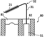
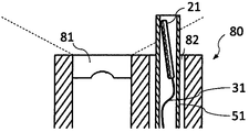
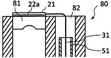
- FIGS. 1 to 6 are views showing the distal end portion of the first cleaning tool in use according to the first embodiment.
- the cleaning tool of Example 1 the cleaning tool shown in FIGS. 1 and 2 was produced.
- the long member 31 is formed by bending a distal end portion of a long member obtained by twisting two wires of nickel titanium alloy to form a bent portion 32, and the cleaning member 21 is provided on the distal end side.
- the total length of the long member is longer than the channel path length of the endoscope. Since superelastic materials are generally expensive, they may be joined with another wire such as a stainless wire in the middle.
- a long member is formed by connecting two kinds of wire rods, a nickel titanium alloy wire 31a on the distal end side and a stainless steel wire 31b on the proximal end side, by caulking joining with a pipe 33. .
- the long member is stored in advance in an outer cylinder 51 that is a tube of elastic fluororesin (PTFE).
- PTFE elastic fluororesin
- the bent portion 32 on the distal end side is deformed, and the cleaning member can be accommodated in the tube. If the long member is pushed out of the outer cylinder, the bent portion comes out of the tube and is restored to its original shape.
- the base end portion of the long member is provided with an operation handle 41, and the long member is easily pulled, pushed out and rotated.
- the proximal end means the side provided with the operation handle, and the distal end means the opposite side.
- a cylindrical low-density polyethylene sponge having a diameter of 1.5 mm and a length of 6 mm was fixed as a cleaning member 21 on the distal end side of the bent portion 32 of the long member 31 by heat welding.
- the tip side of a nickel titanium alloy single wire having a diameter of 0.3 mm was bent to form a bent portion 32.
- the long member was bent so that the angle ⁇ formed between the distal end side and the proximal end side was 68 degrees across the bent portion of the long member.
- the front end 21a of the long member of the cleaning tool is bent in a direction approaching the lens surface, the envelope of the cleaning member on the lens surface side of the endoscope and the axis direction of the endoscope are perpendicular to each other.
- the cleaning member is arranged so that the distance from the surface becomes smaller toward the tip.
- the distal end side including the cleaning member of the cleaning tool was inserted from the treatment instrument insertion channel 82 of the endoscope 80 to the distal end of the endoscope.
- the distal end side including the cleaning member of the cleaning tool is protruded from the distal end of the endoscope, the proximal end portion of the long member is rotated, and the direction of the cleaning member is adjusted so that the cleaning member is positioned above the endoscope lens 81. did.
- the tip of the cleaning member first comes into contact with the lens.
- the cleaning member When the elongate member is further pulled toward the base end side, the cleaning member gradually contacts the lens toward the base end side as the external member receives deformation from the lens at the bent portion of the elongate member. Then, as shown in FIG. 6, the lens from the distal end 21a to the proximal end 21b of the cleaning member finally contacted the lens. Then, by rotating the proximal end side of the long member, the cleaning member was swung like a wiper to remove dirt on the endoscope lens, and the lens was cleaned.
- FIGS. 7 to 8 are diagrams showing a tip portion of the first cleaning tool in use according to the second embodiment, and FIG. 7 shows a state where the cleaning member and the lens surface of the endoscope are not in contact with each other.
- FIG. 8 shows a state in which the cleaning member and the lens surface of the endoscope are brought into contact with each other.
- a first cleaning tool was produced in the same manner as the first cleaning tool according to Example 1 except for the conditions described below.
- the bent wire 32 was formed by bending the tip end side of a cobalt nickel alloy single wire having a diameter of 0.3 mm.
- the bent portion was bent so that the angle ⁇ formed by the distal end side and the proximal end side was 90 degrees across the bent portion of the long member.
- a nylon thread having a diameter of 15 ⁇ m was planted on the distal end side of the long member by electrostatic flocking as the cleaning member 21 on the distal end side from the bent portion.
- the implanted nylon thread was cut, the tip side 21a was 0.8 mm, the length was shortened sequentially, and the bent part side 21b was 0.2 mm.
- the bent portion of the long member is bent in the direction in which the distal end portion of the long member is parallel to the lens surface, but the length of the bristles of the brush is inclined. .
- the lens surface 81 of the endoscope is parallel to a plane perpendicular to the axial direction of the endoscope. For this reason, the distance between the envelope of the cleaning member on the lens surface side of the endoscope and the surface perpendicular to the axial direction of the endoscope decreases toward the distal end of the cleaning member.
- the mechanism of contact between the cleaning member and the lens surface is the same as in the first embodiment.
- FIG. 9 is a diagram illustrating the distal end portion of the first cleaning tool according to the third embodiment when in use.
- a first cleaning tool was produced in the same manner as the first cleaning tool according to Example 1 except for the conditions described below.
- As the long member 31 a nickel titanium alloy single wire having a diameter of 0.2 mm was folded in half.
- An acrylic thread having a diameter of 0.07 mm was sandwiched by 5 mm from the position where the single wire was folded in half, and the metal wire was twisted to plant brush hair as a cleaning member on the distal end side of the long member. Thereafter, the planted acrylic yarn was cut, and the cleaning member as a whole was cylindrical with a diameter of 5 mm and a length of 6 mm.
- the position of the long member on the base end side with respect to the cleaning member was bent to form the bent portion 32.
- the bent portion was bent so that the angle ⁇ formed between the distal end side and the proximal end side was 68 degrees across the bent portion of the long member.
- the leading edge of the long member was bent in a direction away from the endoscope lens. According to the present embodiment, since the tip of the long member is gently bent in the direction away from the lens, it is possible to prevent the tip of the long member from contacting the lens and damaging the lens.
- Example 4 A first cleaning tool according to Example 4 was produced in the same manner as the first cleaning tool according to Example 1 except for the conditions described below.
- the long member 31 the front end side of a cobalt nickel alloy single wire having a diameter of 1 mm was bent to form a bent portion 32.
- the bent portion was bent so that the angle ⁇ formed between the distal end side and the proximal end side was 80 degrees across the bent portion of the long member.
- Three circular openings with a diameter of 0.2 mm were provided along the long axis direction at a position of 30 degrees in the circumferential direction from the side facing the endoscope lens on the front end side of the bent portion of the long member.
- a rectangular parallelepiped silicone rubber having a length of 6 mm, a thickness of 0.5 mm, and a height of 0.5 mm was adhered as an cleaning member 21 at a position facing the endoscope lens on the tip side from the bent portion.
- a connecting portion and an operation handle were formed at the base end of the long member so that a syringe could be connected. Since the opening communicates with the proximal end syringe, when physiological saline was injected from the syringe, the physiological saline was released from the distal end opening. Not only physiological saline but also liquid such as purified water or cleaning agent, and gas can be injected and released. According to the present embodiment, the cleaning member is closely attached to the endoscope lens surface, and the physiological saline can be discharged when the cleaning lens member cleans the lens surface of the endoscope. could be removed.
- FIG. 10 is a view showing the distal end portion of the cleaning tool according to the comparative example in use.
- a cleaning tool shown in FIG. 10 was produced as the cleaning tool of the comparative example in the same manner as the first cleaning tool according to Example 1 except for the conditions described below.
- the tip side of a nickel titanium alloy single wire having a diameter of 0.3 mm was bent to form a bent portion 132.
- the bent portion was bent so that the angle formed by the distal end side and the proximal end side was 90 degrees across the bent portion of the long member.
- a cylindrical low-density polyethylene sponge having a diameter of 1.5 mm and a length of 6 mm was fixed as a cleaning member 121 to the tip side from the bent portion by heat welding.
- the envelope of the cleaning member on the lens surface side of the endoscope was parallel to a plane perpendicular to the axial direction of the endoscope.
- the cleaning tool of the comparative example was housed in the outer cylinder 151, inserted from the treatment instrument insertion port of the endoscope 80 into the endoscope channel 82, and the cleaning member was opposed to the lens surface 81.
- the cleaning member When the cleaning member is pressed against the lens, the long member comes into contact with the edge of the treatment instrument insertion channel opening as shown in FIG. 11, and the cleaning member floats from the lens with the fulcrum as a fulcrum. It could not be brought into close contact with the lens surface of the mirror. For this reason, even if the cleaning member is swung on the endoscope lens, the dirt cannot be wiped off.
- Second endoscope lens cleaning tool (Example 5) 12 to 15 are views showing the distal end portion in use of the second cleaning tool according to the fifth embodiment.
- a second cleaning tool was produced in the same manner as the first cleaning tool according to Example 1 except for the conditions described below.
- a cylindrical low-density polyethylene sponge having a diameter of 1.0 mm and a length of 6 mm was cut in half as the cleaning member 21 on the distal end side from the bent portion 32 of the long member 31, The long member and the longitudinal axis of each one of white and blue were aligned and fixed by heat welding.
- the tip side of a nickel titanium alloy single wire having a diameter of 0.3 mm was bent to form a bent portion 32.
- the blue portion of the cleaning member faces the lens surface of the endoscope when protruding from the lower side of the bent portion, that is, from the treatment instrument insertion port of the endoscope.
- the color of the cleaning member is divided between the side facing the lens and the opposite side, thereby forming an identification unit.
- the color can be confirmed in the endoscopic image. it can.
- the long member can be pushed out of the outer cylinder and the distal end side can be restored to the center side of the endoscope with respect to the bent portion.
- the visual field of the endoscope is a portion indicated by broken lines at both ends of the endoscope lens 81 in FIG.
- reference numeral 90 indicates a frame of the endoscopic image.
- the tip cleaning member is swung like a wiper to The lens was cleaned by wiping off the dirt.
- twist the outer cylinder until the color on the side facing the lens is visible, and then rotate the outer cylinder toward the outer circumference of the endoscope. Can be prevented from protruding.
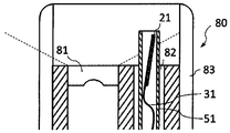
- FIGS. 16 to 21 are views showing the distal end portion of the second cleaning tool according to the sixth embodiment in use.
- a second cleaning tool was produced in the same manner as the first cleaning tool according to Example 1 except for the conditions described below.
- the tip side of a cobalt nickel alloy single wire having a diameter of 0.3 mm was bent to form a bent portion 32.
- a nylon thread having a diameter of 15 ⁇ m was planted on the distal end side of the long member by electrostatic flocking as a cleaning member 21 at a position facing the lens surface of the endoscope at the distal end side from the bent portion.
- the cleaning member 21 is provided only on the side of the long member facing the lens. Thereby, an identification part is comprised.
- the long wire rod 31 is exposed on the side opposite to the side facing the lens.
- FIGS. 17 and 18 if the wire is visible in the endoscopic image, it can be understood that even if the long member is pushed out, it does not face the lens. Therefore, as shown in FIG. 19, the outer cylinder 51 is twisted and rotated. .
- FIG. 20 if the long member is not visible, that is, if the cleaning member is pushed out in an endoscopic image, the long member is pushed out from the bent portion of the long member as shown in FIG. Can be restored to the center side of the endoscope. Therefore, even when the hood 83 is attached to the endoscope as shown in FIG. 17, the lens can be cleaned without causing the cleaning member and the hood to interfere with each other.
Landscapes
- Health & Medical Sciences (AREA)
- Life Sciences & Earth Sciences (AREA)
- Physics & Mathematics (AREA)
- Surgery (AREA)
- Optics & Photonics (AREA)
- Biomedical Technology (AREA)
- Public Health (AREA)
- Nuclear Medicine, Radiotherapy & Molecular Imaging (AREA)
- Pathology (AREA)
- Radiology & Medical Imaging (AREA)
- Veterinary Medicine (AREA)
- Engineering & Computer Science (AREA)
- Molecular Biology (AREA)
- Biophysics (AREA)
- Medical Informatics (AREA)
- Heart & Thoracic Surgery (AREA)
- Animal Behavior & Ethology (AREA)
- General Health & Medical Sciences (AREA)
- General Physics & Mathematics (AREA)
- Astronomy & Astrophysics (AREA)
- Endoscopes (AREA)
- Instruments For Viewing The Inside Of Hollow Bodies (AREA)
Abstract
本発明の第1の内視鏡用レンズ清掃具は、弾性変形可能な長尺部材と、長尺部材の先端部の外周面に固定されており、清掃部材を備え、長尺部材は先端側に屈曲部を有し、清掃部材は、当該長尺部材が内視鏡の処置具挿通チャンネルに挿通されて内視鏡先端から突出したとき、内視鏡のレンズ面側における清掃部材の包絡線が、内視鏡の軸方向と垂直な面に対して非平行である部分を有する。また、本発明の第2の内視鏡用レンズ清掃具は、弾性変形可能な長尺部材と、長尺部材の先端部の外周面に固定されており、清掃部材と、長尺部材と清掃部材を収納可能な外筒を備え、長尺部材は清掃部材より基端側に屈曲部を有し、清掃部材が内視鏡のレンズ面と対向している。
Description
本発明は、内視鏡の処置具挿通チャンネルを経由して、内視鏡の先端に設けられた対物レンズ、照明レンズを清掃するための内視鏡用レンズ清掃具に関するものである。
従来、人体内に挿入し、先端に設けられた対物レンズや照明レンズによって体腔内を観察するための内視鏡が知られている。内視鏡を用いた胃や大腸の検査やESD(内視鏡的粘膜下層剥離術)等の処置の最中には、内視鏡のレンズ面へ、粘液や便塊、高周波処置具での粘膜の切開に伴う組織からの脂肪分などが付着することがある。
そこで特許文献1では、内視鏡のレンズ表面に向けて空気や水を噴射するノズルを備える内視鏡が開示されている。これにより術者が内視鏡を体腔内から抜去することなく、対物レンズ表面に付着した汚れを除去できる。
また、特許文献2では先端が環状に形成された弾性の長尺部材の先端に清掃部材を備えた内視鏡レンズ清掃用の清掃具が開示されている。これにより術者が内視鏡を体腔内から抜去することなく、レンズ表面に付着した汚れを除去できる。
さらに、特許文献3では内視鏡の外周部に設けられたチャンネルを通り、先端を内視鏡先端の固定穴に固定したL字型の清掃具が開示されている。これにより術者が内視鏡を体腔内から抜去することなく、レンズ表面に付着した汚れを除去できる。
しかしながら、強力に付着した付着物は特許文献1に示すようなノズルでは完全に除去できないことがあり、内視鏡の視野の欠損やぼけを発生させ、高精度の検査や処置に悪影響を及ぼす可能性がある。そのため現状では術者は一般的に内視鏡を一旦患者から抜去してからレンズを綿布や綿棒などで拭って汚れを除去し、再び内視鏡を患者に挿入する必要があるが、それは検査、処置時間の増大となり、術者、患者ともに精神的、肉体的負担が大きくなる。
また、特許文献2に示す清掃具では、内視鏡先端で清掃部材を展開した際に内視鏡先端から環状の部材が突出するため、部材が患者の体腔内粘膜に意図せず接触する可能性が高くなり、術者の手技に影響を与える可能性がある。特に、内視鏡の先端のチャンネル開口部から突出させたときに、どの方向に清掃部材が復元するかが内視鏡画像から識別できず、部材が患者の体腔内粘膜に意図せず接触する可能性が高くなり、術者の手技に影響を与える可能性がある。また、内視鏡の検査、処置の際には、内視鏡先端に視野確保のために内視鏡先端フードと言われる円筒形のアタッチメントを取り付けることがあるが、上記と同様の理由で環状の部材と内視鏡先端フードが干渉すると術者の手技に影響を与える可能性がある。
さらに、特許文献3に示す清掃具は専用の内視鏡を必要とし、患者の体腔内に挿入する前に内視鏡にセットしておかなければならず、清掃具が必要となるケースのあるなしに関わらず、清掃具を消費せざるを得ない。また、清掃性を高めるためレンズ面に押し付け力を発生させようと清掃具の長手部を基端側に引っ張ると、清掃具を挿通しているチャンネルの開口部辺縁もしくは内視鏡先端の辺縁部を支点として清掃用部材が持ち上がってしまい、所望の部位を均一に清掃することが困難になることが考えられる。
そこで本発明は、これらの課題に鑑みてなされたものであり、内視鏡のレンズ面に付着した付着物を確実に除去できる内視鏡用レンズ清掃具を提供することを目的とするものである。また、本発明は、清掃具の清掃部材および内視鏡の処置具挿通チャンネルを傷付けにくく、効率的に清掃を行うことができる清掃具を提供することを目的とするものでもある。
本発明の内視鏡用レンズ清掃具は、前記課題を解決するために以下の構成を備える。
(1)本発明の第1の内視鏡用レンズ清掃具は、内視鏡のレンズ面の付着物を除去するものであって、トルクを伝達する弾性変形可能な長尺部材と、長尺部材の先端部の外周面に固定されており、内視鏡のレンズを清掃する清掃部材を備え、長尺部材は先端側に屈曲部を有し、清掃部材が内視鏡のレンズ面と対向しており、清掃部材は、当該長尺部材が内視鏡の処置具挿通チャンネルに挿通されて内視鏡先端から突出して、内視鏡のレンズ面側における清掃部材の包絡線が、内視鏡の軸方向と垂直な面に対して非平行である部分を有するように構成されている。したがって、本発明の内視鏡用レンズ清掃具は、清掃具の手元側から加えられる力を先端側の清掃部材に確実に伝えることができ、所望の部位を均一に清掃することができる。
本発明の構成によれば、レンズ表面に向けて空気や水を噴射させる特許文献1の内視鏡と比べると、レンズ表面に付着した汚れをより効果的に除去できる。また、長尺部材の先端側が屈曲しているので、特許文献2に開示される清掃具より、内視鏡先端からの突出を少なくすることができ、患者の体腔内粘膜と清掃具との意図しない接触や内視鏡先端フードとの干渉も減らすことができる。さらに、清掃部材が内視鏡のレンズ面と対向しており、また、内視鏡のレンズ面側における清掃部材の包絡線が、内視鏡の軸方向と垂直な面に対して非平行である部分を有するように構成されているので、清掃部材とレンズ面との密着性を高めることができ、特許文献3に開示される清掃具と比べると、汚れの除去性能をより高めることができる。さらに、本発明の第1の清掃具は、内視鏡の処置具挿通チャンネルへの抜き差しにより用いるものであるため、特許文献3に開示される清掃具のように、使用不使用に関わらず清掃具をセットする必要がなく、必要に応じて本発明の清掃具を用いればよく、デバイスの無駄遣いを防ぐことができる。
(2)本発明の第1の内視鏡用レンズ清掃具において、包絡線が内視鏡の軸方向と垂直な面に対して勾配を有することが好ましい。勾配があることにより、清掃部材の先端から基端までをレンズ面に接触させることができる。
(3)本発明の第1の内視鏡用レンズ清掃具において、包絡線と、内視鏡の軸方向と垂直な面との距離が、長尺部材の先端側がより小さいことが好ましい。先端側の距離がより小さいことにより、清掃部材の先端から基端までを確実にレンズ面に接触させることができる。
(4)本発明の第1の内視鏡用レンズ清掃具において、清掃部材が先端に向かって、包絡線と内視鏡の軸方向と垂直な面との距離が小さくなるテーパ形状であることが好ましい。これにより、長尺部材の屈曲角度に関わらず、清掃部材の先端から基端までを確実にレンズ面に接触させることができる。
(5)本発明の第1の内視鏡用レンズ清掃具において、長尺部材の屈曲部は、長尺部材の先端部がレンズ面に対して近づく方向に屈曲していることが好ましい。これにより、清掃部材の形状に関わらず、清掃部材の先端から基端までを確実にレンズ面に接触させることができる。
(6)本発明の第1の内視鏡用レンズ清掃具において、長尺部材の屈曲部は、長尺部材の先端部が内視鏡の軸方向と垂直な面に対して平行な方向に屈曲していることが好ましい。内視鏡の軸方向と垂直な面に対して平行な方向に屈曲とは、長尺部材の屈曲部を挟んだ先端側と基端側のなす角が略90度であることをいう。特別な角度を設定する必要がないため、清掃具の製造がより容易になる。
(7)本発明の第1の内視鏡用レンズ清掃具において、長尺部材および清掃部材を収納可能な樹脂製の長尺の外筒を備えることが好ましい。これにより、内視鏡の処置具挿通チャンネルに対して、先端部に清掃部材を備える長尺部材をよりスムーズに挿脱することができる。また、清掃具と内視鏡を構成する部材とが接触することがないので、清掃具本体や内視鏡を傷めることがない。
(8)本発明の第1の内視鏡用レンズ清掃具において、内視鏡用レンズ清掃具の先端が内視鏡の軸方向と垂直な面に対して離れていく方向に屈曲していることが好ましい。これにより、内視鏡のレンズを長尺部材や清掃部材、またはその他の部材により傷めることを抑えることができる。
(9)本発明の第2の内視鏡用レンズ清掃具は、内視鏡のレンズ面の付着物を除去するものであって、トルクを伝達する弾性変形可能な長尺部材と、長尺部材の先端部の外周面に固定されており、内視鏡のレンズを清掃する清掃部材と、前記長尺部材と前記清掃部材を収納可能な外筒を備え、長尺部材は清掃部材より基端側に屈曲部を有し、清掃部材が内視鏡のレンズ面と対向している。
したがって、本発明の第2の内視鏡用レンズ清掃具は、長尺部材と清掃部材を収納可能な外筒を備えているため、内視鏡の処置具挿通口の栓や処置具挿通チャンネルを経て清掃部材を内視鏡先端にデリバリーする際に、清掃具本体を外筒内に収納することにより、清掃部材と内視鏡の各部が接触することがない。このため、清掃部材および内視鏡の処置具挿通口の栓や処置具挿通チャンネルを傷めることがない。また処置具挿通チャンネルの内面を傷つけることもない。このため、この構成によれば処置具挿通チャンネルに対して長尺部材をよりスムーズに挿脱できる。また、弾性変形可能な長尺部材は清掃部材よりも基端側に屈曲部を有し、清掃部材が内視鏡のレンズ面と対向しているので、清掃部材を含む長尺部材の先端を外筒から突出した際に復元すると清掃部材が内視鏡のレンズ面と接触しやすくなるため、効率的にレンズを清掃することができる。
(10)本発明の第1および第2の内視鏡用レンズ清掃具において、清掃部材は長尺部材の先端部の外周面を被覆するものであることが好ましい。これにより、長尺部材が内視鏡のレンズ面と直接接触しにくくなるため、内視鏡のレンズ面を傷付けるのを防止できる。
(11)本発明の第1および第2の内視鏡用レンズ清掃具は、長尺部材もしくは清掃部材に清掃部材の存在を識別できる識別部を備えていることが好ましい。術者は内視鏡画像を通じて長尺部材および清掃部材が収納された外筒越しに識別部を視認することにより、長尺部材を押し出した際に清掃部材がどの方向に復元するかを認識することができる。
上記(9)および(11)に記載の構成により、本発明の第1および第2の内視鏡用レンズ清掃具は、レンズ表面に向けて空気や水を噴射させる特許文献1の内視鏡より、レンズ表面に付着した汚れを効果的に除去できる。さらに、特許文献2に開示される清掃具より、患者の体腔内粘膜と清掃具の構成部品との意図しない接触や内視鏡先端フードとの干渉も減らせることができる。
(12)本発明の第1および第2の内視鏡用レンズ清掃具において、識別部は、長尺部材が内視鏡の処置具挿通チャンネルに挿通されて内視鏡先端から突出した際に、内視鏡のレンズ面に面する位置または、反対側の位置に位置することが好ましい。いずれかに位置することにより、術者が確実に清掃部材の向きを認識することができる。
(13)本発明の第1および第2の内視鏡用レンズ清掃具において、清掃部材が、長尺部材が内視鏡の処置具挿通チャンネルに挿通されて内視鏡先端から突出した際に、内視鏡のレンズ面に面する位置に設けられていることが好ましい。また、(14)清掃部材が、長尺部材が内視鏡の処置具挿通チャンネルに挿通されて内視鏡先端から突出した際に、内視鏡のレンズ面に面する位置にのみ設けられており、その反対側には設けられていないことが好ましい。清掃部材がレンズ面のみ側に位置すると定まっていることにより、清掃部材を識別部として用いることができる。
(15)本発明の第1および第2の内視鏡用レンズ清掃具において、清掃部材の色が、長尺部材が内視鏡の処置具挿通チャンネルに挿通されて内視鏡先端から突出した際に、内視鏡のレンズ面に面する位置とその反対側の位置とで異なることが好ましい。これにより、術者が確実に清掃部材の向きを認識することができる。
(16)本発明の第1および第2の内視鏡用レンズ清掃具において、長尺部材が中空のチューブ材であり、長尺部材の清掃部材が設けられた部分に開口部を有することが好ましい。これにより、長尺部材の基端部から液体または気体を注入し、開口部から放出しながら、清掃部材によるレンズの清掃が可能になるので、付着物をより確実に除去することができる。また、簡単な構造で液体や気体による洗浄と清掃部材による清掃とを同時に行うことが可能となる。なお、より好ましくは、長尺部材の基端部および清掃部材が設けられた部分に開口部を有する。
(17)本発明の第1および第2の内視鏡用レンズ清掃具において、清掃部材の先端部に内視鏡のレンズより硬度の低い柔軟部を有することが好ましい。これにより、内視鏡のレンズを長尺部材や清掃部材により傷めることを抑えることができる。
(18)本発明の第1および第2の内視鏡用レンズ清掃具において、清掃部材はブラシであること、または(19)清掃部材の材質はエラストマーであることが好ましい。これにより、内視鏡のレンズ面の付着物を効率的に掻き落とすことができる。
(20)本発明の第1および第2の内視鏡用レンズ清掃具において、前記清掃部材の材質は生分解性樹脂であることが好ましい。これにより、清掃部材が体内で脱落したとしても、人体への影響をより小さくすることができる。
本発明によれば、内視鏡先端のレンズ表面に付着した汚れを、患者の体腔内で、従来よりも確実に安全に効率的に除去できる。また、部品点数が少なく、簡略化された構造であるため、製造が容易であり、また安価に製造することができる。
まず、本発明の第1および第2の内視鏡用レンズ清掃具を構成する部材について説明する。
(1)清掃具
本発明の内視鏡用レンズ清掃具は、先端面にレンズを有する内視鏡の処置具挿通チャンネルに挿通され、内視鏡のレンズを清掃するためのものである。以下では、「内視鏡用レンズ清掃具」を単に「清掃具」と記載することもある。内視鏡基端部の処置具挿通チャンネルの基端側開口部から清掃具を挿通し、先端側開口部から清掃部材を含む長尺部材の一部を突出させ、清掃部材をレンズに接触させてレンズの清掃を行う。
(1)清掃具
本発明の内視鏡用レンズ清掃具は、先端面にレンズを有する内視鏡の処置具挿通チャンネルに挿通され、内視鏡のレンズを清掃するためのものである。以下では、「内視鏡用レンズ清掃具」を単に「清掃具」と記載することもある。内視鏡基端部の処置具挿通チャンネルの基端側開口部から清掃具を挿通し、先端側開口部から清掃部材を含む長尺部材の一部を突出させ、清掃部材をレンズに接触させてレンズの清掃を行う。
(2)長尺部材
本発明の内視鏡用レンズ清掃具の長尺部材は、弾性変形可能な材料で形成され、屈曲部を有する。長尺部材の弾性は、内視鏡の処置具挿通チャンネルの変形に沿って形状が変化する程度の弾性であれば足りる。長尺部材の材料は、弾性変形可能な材料であれば特に限定されないが、超弾性合金が好ましく、Ni-Ti系合金、Fe-Mg-Si系合金、Au-Cu-Al系合金、Co-Cr系合金、Co-Ni系合金などが挙げられる。そのほかの材料として超弾性ポリアミドなどの超弾性樹脂が挙げられる。また、少なくとも長尺部材の屈曲部が超弾性を有する材料で形成されていればよいので、当該部分のみを超弾性合金で形成し、その他の部分に異なる素材を用いてもよい。異なる素材としては、ステンレスなどの金属、ナイロンなどの樹脂を用いることができる。異なる材料を用いる場合は、異なる線材間を通常の接合方法で接合すればよい。例えば、金属管でかしめて結合する、溶接、溶着や接着するなどの方法がある。長尺部材の屈曲部を超弾性や弾性変形可能な材料で構成することで、清掃部材、屈曲部を含む長尺部材の先端を外筒から突出した際に確実に屈曲部を元の形状に復元し、効率的にレンズを清掃することができる。
本発明の内視鏡用レンズ清掃具の長尺部材は、弾性変形可能な材料で形成され、屈曲部を有する。長尺部材の弾性は、内視鏡の処置具挿通チャンネルの変形に沿って形状が変化する程度の弾性であれば足りる。長尺部材の材料は、弾性変形可能な材料であれば特に限定されないが、超弾性合金が好ましく、Ni-Ti系合金、Fe-Mg-Si系合金、Au-Cu-Al系合金、Co-Cr系合金、Co-Ni系合金などが挙げられる。そのほかの材料として超弾性ポリアミドなどの超弾性樹脂が挙げられる。また、少なくとも長尺部材の屈曲部が超弾性を有する材料で形成されていればよいので、当該部分のみを超弾性合金で形成し、その他の部分に異なる素材を用いてもよい。異なる素材としては、ステンレスなどの金属、ナイロンなどの樹脂を用いることができる。異なる材料を用いる場合は、異なる線材間を通常の接合方法で接合すればよい。例えば、金属管でかしめて結合する、溶接、溶着や接着するなどの方法がある。長尺部材の屈曲部を超弾性や弾性変形可能な材料で構成することで、清掃部材、屈曲部を含む長尺部材の先端を外筒から突出した際に確実に屈曲部を元の形状に復元し、効率的にレンズを清掃することができる。
長尺部材は、単線であっても、単線をより合わせた撚線であってもよい。単線であれば、製造が容易であり、撚線であれば、長尺部材の強度を上げることができるので、基端側の回転操作をより確実に先端部に伝えることができるなど、清掃部材の操作性を向上させることができる。また、長尺部材の途中部分で線状部材がつなぎ合わされている構造であってもよい。長尺部材の長さは、先端側でレンズの清掃、基端側で長尺部材の操作を行うために、処置具挿通チャンネルより長いことが必要である。
また、長尺部材は、中空のチューブ状部材であってもよい。チューブ状部材とし、さらに清掃部材を形成する位置(より好ましくは基端部と清掃部材を形成する位置の両方)にチューブの外部と連通する開口部を設けることによって、長尺部材の基端側から送り込まれた液体や気体などを開口部から放出することができる。清掃部材による付着物の除去時に、液体や気体を放出することにより、付着物の除去をより確実にすることができる。液体や気体などの送出は、長尺部材の基端側開口部にシリンジなどを接続することにより行うことができる。
(3)屈曲部
第1の清掃具の長尺部材は、先端側に屈曲部を有する。また、第2の清掃具の長尺部材は、清掃部材より基端側に屈曲部を有する。本発明の第1および第2の内視鏡用レンズ清掃具は、内視鏡の処置具挿通チャンネルや外筒に挿通されたとき、長尺部材の屈曲部が、弾性により、処置具挿通チャンネルや外筒の形状に沿う形状となる。そして、長尺部材の屈曲部は、処置具挿通チャンネルから突出したときに、弾性力により元の形状に復元されて、清掃部材が内視鏡の先端面に対向するようになる。そして抜去されるときにも、長尺部材の先端側の屈曲部は、弾性を有するため、処置具挿通チャンネルや外筒の形状に沿う形状となる。これにより、スムーズに処置具挿通チャンネルへの抜き差しを行うことができる。
第1の清掃具の長尺部材は、先端側に屈曲部を有する。また、第2の清掃具の長尺部材は、清掃部材より基端側に屈曲部を有する。本発明の第1および第2の内視鏡用レンズ清掃具は、内視鏡の処置具挿通チャンネルや外筒に挿通されたとき、長尺部材の屈曲部が、弾性により、処置具挿通チャンネルや外筒の形状に沿う形状となる。そして、長尺部材の屈曲部は、処置具挿通チャンネルから突出したときに、弾性力により元の形状に復元されて、清掃部材が内視鏡の先端面に対向するようになる。そして抜去されるときにも、長尺部材の先端側の屈曲部は、弾性を有するため、処置具挿通チャンネルや外筒の形状に沿う形状となる。これにより、スムーズに処置具挿通チャンネルへの抜き差しを行うことができる。
(4)清掃部材
清掃部材は、内視鏡のレンズを清掃するためのものである。長尺部材の先端部の外周面は、清掃部材に固定されている。清掃部材は、処置具挿通チャンネルに挿通されて内視鏡の先端部から突出したとき、内視鏡の先端面に対向する。長尺部材の先端部の外周面は、清掃部材によって一部または全部が被覆されていてもよい。これにより、長尺部材が内視鏡のレンズ面と直接接触しにくくなるため、内視鏡のレンズ面を傷付けるのを防止できる。
清掃部材は、内視鏡のレンズを清掃するためのものである。長尺部材の先端部の外周面は、清掃部材に固定されている。清掃部材は、処置具挿通チャンネルに挿通されて内視鏡の先端部から突出したとき、内視鏡の先端面に対向する。長尺部材の先端部の外周面は、清掃部材によって一部または全部が被覆されていてもよい。これにより、長尺部材が内視鏡のレンズ面と直接接触しにくくなるため、内視鏡のレンズ面を傷付けるのを防止できる。
清掃部材は例えばブラシ、スポンジ、柔軟なプラスチック片、不織布などが挙げられる。ブラシである場合、付着物の除去の確実性を上げることができるので好ましい。清掃部材の材料は、ナイロン、ポリプロピレン、塩化ビニル、ポリアミド、ポリエステル、アクリル、ポリウレタン、ポリスチレン、ポリオレフィン、シリコーン、レーヨン、ゴム、ナイロンエラストマー、エステルエラストマー、ウレタンエラストマー、オレフィンエラストマー、綿、絹など、種々の材料を選択することができる。材料をエラストマーとし、内視鏡のレンズ面に対し角度をつけたエッジを有する形状などブレード状の形状とすることで、付着物をより確実に除去することができる。また、生体内で用いるものであるため、安全性をより高めるために生分解性樹脂を用いることも好ましい。清掃部材は、内視鏡のレンズと接するため、レンズを傷つけることがなく、かつ付着物を除去できる強度や腰の強さをもつものを選択することが好ましい。
清掃部材を長尺部材に固定するには、例えば清掃部材がブラシである場合、長尺部材を二本の線材とし、その間に毛を挟み込み線材を撚ってブラシ状にする方法や、長尺部材に静電植毛によりブラシの毛を固定する方法など任意の方法を採用することができる。スポンジやプラスチック片、不織布の場合は、熱による溶着や接着剤による接着、上記のように長尺部材に挟み込むことなどにより長尺部材と清掃部材を固定することができる。
(5)外筒
本発明の第1の清掃具は、長尺部材およびその先端に位置する清掃部材を収納可能な樹脂製の長尺の外筒を備えることが好ましい。また、本発明の第2の清掃具は、長尺部材およびその先端に位置する清掃部材を収納可能な外筒を備える。外筒内に長尺部材および清掃部材を収納し、清掃部材を保護することができるので、内視鏡の処置具挿通口の栓、処置具挿通チャンネルを経て清掃部材を内視鏡先端にデリバリーする際に、清掃部材を傷めることがない。また処置具挿通チャンネルの内面を傷つけることもない。このため、この構成によれば処置具挿通チャンネルに対して長尺部材をよりスムーズに挿脱することができる。外筒の材料は、特に限定されないが、樹脂製や金属製が好ましく、内視鏡の処置具挿通チャンネルの変形に沿って形状が変化する弾性を有する材料であることが好ましい。樹脂であれば、例えば、PTFE(ポリテトラフルオロエチレン)、PP(ポリプロピレン)などが好ましい。外筒は、内視鏡画像で清掃部材の向きを確認するために、透明材料で形成することもできる。外筒を透明または半透明の材料としない場合は、外筒の側壁に小孔を設けるなど外筒に開口部を設けたり、外筒を網状に形成するなどして、外筒内の清掃具を視認できるように構成することが好ましい。
本発明の第1の清掃具は、長尺部材およびその先端に位置する清掃部材を収納可能な樹脂製の長尺の外筒を備えることが好ましい。また、本発明の第2の清掃具は、長尺部材およびその先端に位置する清掃部材を収納可能な外筒を備える。外筒内に長尺部材および清掃部材を収納し、清掃部材を保護することができるので、内視鏡の処置具挿通口の栓、処置具挿通チャンネルを経て清掃部材を内視鏡先端にデリバリーする際に、清掃部材を傷めることがない。また処置具挿通チャンネルの内面を傷つけることもない。このため、この構成によれば処置具挿通チャンネルに対して長尺部材をよりスムーズに挿脱することができる。外筒の材料は、特に限定されないが、樹脂製や金属製が好ましく、内視鏡の処置具挿通チャンネルの変形に沿って形状が変化する弾性を有する材料であることが好ましい。樹脂であれば、例えば、PTFE(ポリテトラフルオロエチレン)、PP(ポリプロピレン)などが好ましい。外筒は、内視鏡画像で清掃部材の向きを確認するために、透明材料で形成することもできる。外筒を透明または半透明の材料としない場合は、外筒の側壁に小孔を設けるなど外筒に開口部を設けたり、外筒を網状に形成するなどして、外筒内の清掃具を視認できるように構成することが好ましい。
(6)操作ハンドル
また、術者が、本発明の清掃具を処置具挿通チャンネルへ挿通する際や、清掃部材を内視鏡のレンズに接触させたり、長尺部材をその中心軸回りに回転させて清掃部材を揺動させる際などの操作を容易にするために、長尺部材の基端側に、操作ハンドルを設けることができる。術者は操作ハンドルを把持、回転することで清掃具を操作することができる。操作ハンドルは、長尺部材の外径よりも太い外径を持つことが好ましい。これにより、術者は長尺部材をより回転操作しやすくなる。また、基端側で高いトルクを発生することが可能になるので、先端の清掃部材の揺動による汚れの除去性能を高くすることができる。
また、術者が、本発明の清掃具を処置具挿通チャンネルへ挿通する際や、清掃部材を内視鏡のレンズに接触させたり、長尺部材をその中心軸回りに回転させて清掃部材を揺動させる際などの操作を容易にするために、長尺部材の基端側に、操作ハンドルを設けることができる。術者は操作ハンドルを把持、回転することで清掃具を操作することができる。操作ハンドルは、長尺部材の外径よりも太い外径を持つことが好ましい。これにより、術者は長尺部材をより回転操作しやすくなる。また、基端側で高いトルクを発生することが可能になるので、先端の清掃部材の揺動による汚れの除去性能を高くすることができる。
(7)その他の構成
本発明の清掃具の先端が、内視鏡の軸方向と垂直な面に対して離れていく方向に屈曲していてもよい。清掃具の先端は、清掃部材の先端であってもよく、長尺部材の先端であってもよい。また、内視鏡の軸方向と垂直な面に対して離れていく方向に屈曲している他の部材が、清掃部材や長尺部材に取り付けられることにより、清掃具の先端が屈曲していてもよい。例えば、清掃部材の最先端側には、内視鏡のレンズ面から離れていく方向に屈曲する清掃部材屈曲部を設けてもよい。このようにすることで、清掃部材の先端部や長尺部材で、レンズ面を傷つけることを防ぐことができる。
本発明の清掃具の先端が、内視鏡の軸方向と垂直な面に対して離れていく方向に屈曲していてもよい。清掃具の先端は、清掃部材の先端であってもよく、長尺部材の先端であってもよい。また、内視鏡の軸方向と垂直な面に対して離れていく方向に屈曲している他の部材が、清掃部材や長尺部材に取り付けられることにより、清掃具の先端が屈曲していてもよい。例えば、清掃部材の最先端側には、内視鏡のレンズ面から離れていく方向に屈曲する清掃部材屈曲部を設けてもよい。このようにすることで、清掃部材の先端部や長尺部材で、レンズ面を傷つけることを防ぐことができる。
清掃部材の先端側には、内視鏡のレンズより硬度の低い柔軟部を設けてもよい。このようにすることで、清掃部材の先端部がレンズに接した際にレンズ面を傷つけることを防ぐことができる。この場合、清掃具の最先端部がこの柔軟部であることが好ましい。
次に、本発明の第1および第2の清掃具について説明する。
(8)第1の内視鏡用レンズ清掃具
本発明の第1の清掃具は、内視鏡のレンズ面の付着物を除去するものであって、トルクを伝達する弾性変形可能な長尺部材と、長尺部材の先端部の外周面に固定されており、内視鏡のレンズを清掃する清掃部材を備え、長尺部材は先端側に屈曲部を有し、清掃部材が内視鏡のレンズ面と対向しており、清掃部材は、当該長尺部材が内視鏡の処置具挿通チャンネルに挿通されて内視鏡先端から突出して、内視鏡のレンズ面側における清掃部材の包絡線が、内視鏡の軸方向と垂直な面に対して非平行である部分を有する。
(8)第1の内視鏡用レンズ清掃具
本発明の第1の清掃具は、内視鏡のレンズ面の付着物を除去するものであって、トルクを伝達する弾性変形可能な長尺部材と、長尺部材の先端部の外周面に固定されており、内視鏡のレンズを清掃する清掃部材を備え、長尺部材は先端側に屈曲部を有し、清掃部材が内視鏡のレンズ面と対向しており、清掃部材は、当該長尺部材が内視鏡の処置具挿通チャンネルに挿通されて内視鏡先端から突出して、内視鏡のレンズ面側における清掃部材の包絡線が、内視鏡の軸方向と垂直な面に対して非平行である部分を有する。
本発明の第1の清掃具は、内視鏡のレンズ面側における清掃部材の包絡線が、前内視鏡の軸方向と垂直な面に対して非平行である部分を有するように構成されている。このため、長尺部材を軸方向の基端側へ引くことにより、包絡線と内視鏡の軸方向と垂直な面との距離がゼロになり、清掃部材と内視鏡レンズを密着させることができる。
「内視鏡のレンズ面側における清掃部材の包絡線が、内視鏡の軸方向と垂直な面に対して非平行」とは、例えば、前記包絡線と、内視鏡の軸方向と垂直な面との距離が、清掃部材の先端側から屈曲部側にかけて徐々に広くなる構成、狭くなる構成、周期的に変化する構成、ランダムに変化する構成などが挙げられる。
本発明の第1の内視鏡用レンズ清掃具において、包絡線が内視鏡の軸方向と垂直な面に対して勾配を有することが好ましい。例えば、包絡線と、内視鏡の軸方向と垂直な面との距離が徐々に広くまたは狭くなることが好ましい。清掃部材と内視鏡レンズを密着させるためには、清掃部材の先端側から屈曲部にかけて前記距離が徐々に広くなる構成、つまり、先端側がより内視鏡レンズ面に近い構成が好ましい。このように、前記包絡線と、内視鏡の軸方向と垂直な面との距離が、長尺部材の先端側がより小さいことが好ましい。清掃具をこのような構成にすることにより、長尺部材を基端側に引くと、まず清掃部材の先端がレンズに接触する。更に長尺部材を引くと、長尺部材の屈曲部のレンズから受ける外力による変形に伴い清掃部材の基端側が徐々にレンズに接触していく。最後は清掃部材の先端から基端までがレンズに接触するようにして、清掃部材と内視鏡レンズを密着させることができる。
また、清掃部材自身の形状が、先端に向かって、前記包絡線と、内視鏡の軸方向と垂直な面との距離が小さくなるテーパ形状であることが好ましい。これにより、屈曲部の形状に関わらず、清掃部材の先端側を、内視鏡レンズ面により近づけることができる。このようなテーパ形状として、清掃部材の基端部を底辺とし、先端部にかけて徐々に先細りになった円錐台形状や四角錐台形状、レンズ面側のみ先端部に向かって小さくなる形状などが挙げられる。
長尺部材の屈曲部の形状は、清掃部材の先端が内視鏡のレンズ面に対して近づく方向に屈曲していることが好ましい。その形状として長尺部材の先端側が短辺、基端部側が長辺となるL字状の形状が挙げられる。また、屈曲部は、屈曲部を挟んだ先端側と基端側が角度を有するように曲げられていてもよく、カーブを描くように曲げられていてもよい。また、波打った形状であってもよい。長尺部材の先端が、内視鏡のレンズ面に対して近づく方向に屈曲していれば、清掃部材が長尺部材の長軸に平行な形状であった場合にも、清掃部材の先端が内視鏡のレンズ面に対して近づくことになるので好ましい。
さらに、屈曲部は長尺部材の先端部が、内視鏡の軸方向と垂直な面に対して平行な方向に屈曲していることが好ましい。また、屈曲部は長尺部材の先端部が、内視鏡のレンズ面に対して平行な方向に屈曲していてもよい。この場合、清掃部材の形状を、清掃部材の先端部がレンズ面に近づきやすい形状にすることで、清掃部材のレンズへの密着性を高めることができる。
(9)第2の内視鏡用レンズ清掃具
本発明の第2の清掃具は、内視鏡のレンズ面の付着物を除去するものであって、トルクを伝達する弾性変形可能な長尺部材と、長尺部材の先端部の外周面に固定されており、内視鏡のレンズを清掃する清掃部材と、長尺部材と清掃部材を収納可能な外筒を備え、長尺部材は清掃部材より基端側に屈曲部を有し、清掃部材が内視鏡のレンズ面と対向している。
したがって、本発明の第2の内視鏡用レンズ清掃具は、長尺部材と清掃部材を収納可能な外筒を備えているため、内視鏡の処置具挿通口の栓や処置具挿通チャンネルを経て清掃部材を内視鏡先端にデリバリーする際に、清掃具本体を外筒内に収納することにより、清掃部材と内視鏡の各部が接触することがない。このため、清掃部材をおよび内視鏡の処置具挿通口の栓や処置具挿通チャンネルを傷めることがない。また処置具挿通チャンネルの内面を傷つけることもない。このため、この構成によれば処置具挿通チャンネルに対して長尺部材をよりスムーズに挿脱できる。また、弾性変形可能な長尺部材の先端側に屈曲部を有するので、清掃部材を含む長尺部材の先端を外筒から突出した際に復元し、効率的にレンズを清掃することができる。
本発明の第2の清掃具は、内視鏡のレンズ面の付着物を除去するものであって、トルクを伝達する弾性変形可能な長尺部材と、長尺部材の先端部の外周面に固定されており、内視鏡のレンズを清掃する清掃部材と、長尺部材と清掃部材を収納可能な外筒を備え、長尺部材は清掃部材より基端側に屈曲部を有し、清掃部材が内視鏡のレンズ面と対向している。
したがって、本発明の第2の内視鏡用レンズ清掃具は、長尺部材と清掃部材を収納可能な外筒を備えているため、内視鏡の処置具挿通口の栓や処置具挿通チャンネルを経て清掃部材を内視鏡先端にデリバリーする際に、清掃具本体を外筒内に収納することにより、清掃部材と内視鏡の各部が接触することがない。このため、清掃部材をおよび内視鏡の処置具挿通口の栓や処置具挿通チャンネルを傷めることがない。また処置具挿通チャンネルの内面を傷つけることもない。このため、この構成によれば処置具挿通チャンネルに対して長尺部材をよりスムーズに挿脱できる。また、弾性変形可能な長尺部材の先端側に屈曲部を有するので、清掃部材を含む長尺部材の先端を外筒から突出した際に復元し、効率的にレンズを清掃することができる。
本発明の第2の内視鏡用レンズ清掃具は、長尺部材もしくは清掃部材に清掃部材の存在を識別できる識別部を備えていることが好ましい。これにより、術者は内視鏡画像を通じて長尺部材および清掃部材が収納された外筒越しに識別部を視認することにより、長尺部材を押し出した際の長尺部材の屈曲部よりも先端側がどの方向に復元するかを認識することができる。もし、復元の方向が内視鏡の外側に向くようであれば、術者内視鏡の処置具挿通口から出ている外筒と長尺部材を同時に捻って清掃具全体を回転させ、復元の方向を内視鏡の中心側に修正することができる。よって特許文献2に開示される清掃具より、患者の体腔内粘膜と清掃具の構成部品との意図しない接触や内視鏡先端フードとの干渉も減らせることができる。
なお、清掃具が外筒の内面と接しており摩擦力により係止している場合には、外筒のみを回転することにより、清掃具を所望の方向に向けることができる。また、外筒の有無にかかわらず、清掃具のみを回転させることにより、清掃具を所望の方向に向けることもできる。
識別部は、清掃部材の内視鏡に面する面を示すものであれば、特に構成を問わず、例えば、長尺部材の内視鏡のレンズ面に面する位置またはその反対側に識別部材としてマーカーを付してもよい。また、長尺部材のレンズ面に面する側またはその反対側を着色してもよい。あるいは、清掃部材を二色で構成し、一方の色の部位を内視鏡のレンズ面に面する位置に配置し、他方の色をその反対の位置に配置してもよい。このように清掃部材を内視鏡に面する側のみに設けるなどにより、識別部とすることができる。
以下では、本発明の内視鏡用レンズ清掃具の使用方法について説明する。
本発明の第1および第2の内視鏡用レンズ清掃具は、内視鏡検査、処置中に術者が内視鏡画像によりレンズ面に内視鏡のノズルによる水や空気の噴射では取り除けない汚れが付いたことを確認した際に用いられる。本発明の内視鏡用レンズ清掃具は、内視鏡の処置具挿通口から処置具挿通チャンネルを経て内視鏡先端に向けて挿通される。
このとき、長尺部材は弾性を有するため、屈曲部は処置具挿通チャンネルの形状に沿う形状に変形する。そして、長尺部材の先端部は、内視鏡先端から突出したとき、弾性力により屈曲部の元の形状、例えばL字状に復元し、清掃部材が内視鏡の先端面に対向する。
第1の清掃具の場合には、術者は内視鏡の画像を見ながら、長尺部材を回転させて、長尺部材の先端に付いた清掃部材を内視鏡レンズの上方に位置するように調整する。そのあと長尺部材を基端側に引くことで清掃部材をレンズに押し付ける。ここで、押し付ける前には清掃部材と内視鏡レンズ面との距離は、先端に向かって小さくなっているので、長尺部材を基端側に引くと、まず清掃部材の先端がレンズに接触する。更に長尺部材を基端側に引くと、長尺部材の屈曲部のレンズから受ける外力による変形に伴い清掃部材の基端側が徐々にレンズに接触していく。そして、最後は清掃部材の先端から基端までがレンズに接触する。なお清掃部材がブラシであって長尺部材の先端がブラシ部より突出している場合、レンズを傷つけないよう突出部はレンズから遠ざかる方向にゆるやかに曲げられていることが望ましい。
第2の清掃具の場合には、外筒の先端部を内視鏡先端のチャンネル開口部から突出させた後、術者は、内視鏡画像を通じて長尺部材および清掃部材が収納された外筒越しに識別部の向きを確認することにより、長尺部材を押し出した際の屈曲部よりも先端側がどの方向に復元するかを認識できる。もし、復元の方向が内視鏡の外側に向いていれば、術者が内視鏡の処置具挿通口から出ている外筒または長尺部材を捻って清掃具全体を回転させ、復元の方向を内視鏡の中心側に修正する。さらに、術者は内視鏡の画像を見ながら、長尺部材を回転させて、屈曲部の先端に付いた清掃部材を内視鏡レンズの上方に位置するように微調整する。そのあと外筒を処置具挿通チャンネルに引き込み、さらに長尺部材を基端側に引くことで清掃部材をレンズに押し付ける。
その後、第1清掃具または第2清掃具の長尺部材の基端側を回転させることにより、先端側の清掃部材をワイパーのように揺動させて内視鏡レンズ上の汚れを拭き取るように除去する。このとき内視鏡に備わっているレンズ洗浄用のノズルで水や空気を噴射しながら上記の操作を行うと、より強力に汚れを除去することができる。
内視鏡画像により汚れを除去できたことが確認できたら、長尺部材を内視鏡の処置具挿通口から引いて清掃具を抜去する。処置具挿通チャンネルを通過するときは、挿通するときと同様に、長尺部材の屈曲部は弾性変形するため、処置具挿通チャンネルの形状に沿う形状となる。よって清掃具をスムーズに内視鏡から抜去することができる。
なお、本発明の第1の清掃具を処置具挿通口から挿通するに当たり、予め清掃部材を含む長尺部材の先端部から手元側を外筒に挿通しておくこともできる。第2の清掃具の場合には、処置具挿通口から挿通するに当たり、予め清掃部材を含む長尺部材の先端部から手元側を外筒に挿通しておく。長尺部材は弾性を有するため、屈曲部は変形して外筒の内部に収納することが可能になる。外筒に長尺部材を収納した状態での内視鏡への挿抜が可能になるため、挿通時は内視鏡の処置具挿通口、処置具挿通チャンネル、内視鏡先端側のチャンネル開口部で清掃部材が削れる等のダメージを負うことがなくなり、汚れの除去性能が劣化することがない。また、抜去時は清掃部材に付着した付着物による内視鏡の処置具挿通チャンネルの汚染を防止することができる。
本願は、2015年7月7日に出願された日本国特許出願第2015-136404号および日本国特許出願第2015-136405号に基づく優先権の利益を主張するものである。2015年7月7日に出願された日本国特許出願第2015-136404号および日本国特許出願第2015-136405号の明細書の全内容が、本願に参考のため援用される。
(1)第1の内視鏡用レンズ清掃具
(実施例1)
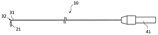
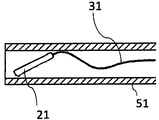
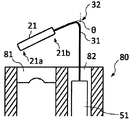
図1~図6は実施例1に係る第1の清掃具の使用状態の先端部を示す図である。
実施例1の清掃具として、図1および図2に示す清掃具を作製した。清掃具10において、長尺部材31は、ニッケルチタン合金の2本の線材を撚り合わせた長尺部材の先端部を曲げて屈曲部32を形成し、その先端側に清掃部材21を設けた。長尺部材の全長は、内視鏡のチャンネル経路長以上の長さである。超弾性材料は一般的に高価なので、途中でステンレスの線材等の別の線材と接合されていてもよい。
(実施例1)
図1~図6は実施例1に係る第1の清掃具の使用状態の先端部を示す図である。
実施例1の清掃具として、図1および図2に示す清掃具を作製した。清掃具10において、長尺部材31は、ニッケルチタン合金の2本の線材を撚り合わせた長尺部材の先端部を曲げて屈曲部32を形成し、その先端側に清掃部材21を設けた。長尺部材の全長は、内視鏡のチャンネル経路長以上の長さである。超弾性材料は一般的に高価なので、途中でステンレスの線材等の別の線材と接合されていてもよい。
本実施例では、図3に示すように、先端側のニッケルチタン合金の線材31aと基端側のステンレスの線材31bの2種類の線材をパイプ33によってカシメ接合で繋いで、長尺部材とする。長尺部材は、図4に示すように、弾性を有するフッ素樹脂(PTFE)のチューブである外筒51内に予め収納する。長尺部材を外筒に挿入することによって先端側の屈曲部32が変形し、清掃部材をチューブ内に収納することができる。長尺部材を外筒から押し出せば屈曲部がチューブの外に出て元の形状に復元する。長尺部材の基端部は操作ハンドル41を備え、長尺部材の引張りや押し出し、回転動作が容易になっている。なお、清掃具において、基端とは、操作ハンドルを備える側、先端とはその反対側をいう。
図5に示すように、長尺部材31の屈曲部32より先端側に清掃部材21として、直径1.5mm、長さ6mmの円筒形の低密度ポリエチレン製のスポンジを熱溶着により固定した。長尺部材31として、直径0.3mmのニッケルチタン合金の単線の先端側を曲げ、屈曲部32を形成した。長尺部材の屈曲部を挟んで先端側と基端側のなす角θの角度が68度となるように曲げた。これにより、清掃具の長尺部材の先端21aがレンズ面に対して近づく方向に屈曲しているため、内視鏡のレンズ面側における清掃部材の包絡線と、内視鏡の軸方向と垂直な面との距離が、清掃部材が先端に向かって小さくなるように配置された。
清掃具の清掃部材を含む先端側を内視鏡80の処置具挿通チャンネル82から内視鏡先端まで挿通した。清掃具の清掃部材を含む先端側を内視鏡先端から突出させ、長尺部材の基端部を回転させ、清掃部材を内視鏡レンズ81の上方に位置するように清掃部材の向きを調整した。長尺部材を基端側に引くと、まず清掃部材の先端がレンズに接触する。更に長尺部材を基端側に引くと、長尺部材の屈曲部のレンズから受ける外力による変形に伴い清掃部材は基端側にかけて徐々にレンズに接触していく。そして、図6に示すように、最後は清掃部材の先端21aから基端21bまでがレンズに接触した。そして、長尺部材の基端側を回転させることにより、清掃部材をワイパーのように揺動させて内視鏡レンズ上の汚れを拭き取るように除去し、レンズを清掃した。
(実施例2)
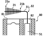
図7~図8は実施例2に係る第1の清掃具の使用状態の先端部を示す図であり、図7は、清掃部材と内視鏡のレンズ面を接触させていない状態を示し、図8は清掃部材と内視鏡のレンズ面を接触させた状態を示している。以下記載の条件以外は、実施例1に係る第1の清掃具と同様にして、第1の清掃具を作製した。図7~図8に示すように、長尺部材31として、直径0.3mmのコバルトニッケル合金の単線の先端側を曲げ、屈曲部32を形成した。屈曲部は、長尺部材の屈曲部を挟んで先端側と基端側のなす角θの角度が90度となるように曲げた。屈曲部より先端側に清掃部材21として、直径15μmのナイロン糸を、静電植毛により長尺部材の先端側に植えつけた。植毛したナイロン糸をカットし、先端側21aを0.8mmとし、順次長さを短くし、屈曲部側21bを0.2mmとした。
図7~図8は実施例2に係る第1の清掃具の使用状態の先端部を示す図であり、図7は、清掃部材と内視鏡のレンズ面を接触させていない状態を示し、図8は清掃部材と内視鏡のレンズ面を接触させた状態を示している。以下記載の条件以外は、実施例1に係る第1の清掃具と同様にして、第1の清掃具を作製した。図7~図8に示すように、長尺部材31として、直径0.3mmのコバルトニッケル合金の単線の先端側を曲げ、屈曲部32を形成した。屈曲部は、長尺部材の屈曲部を挟んで先端側と基端側のなす角θの角度が90度となるように曲げた。屈曲部より先端側に清掃部材21として、直径15μmのナイロン糸を、静電植毛により長尺部材の先端側に植えつけた。植毛したナイロン糸をカットし、先端側21aを0.8mmとし、順次長さを短くし、屈曲部側21bを0.2mmとした。
本実施例2によれば、長尺部材の屈曲部は、長尺部材の先端部がレンズ面に対して平行な方向に屈曲しているが、ブラシの毛の長さに勾配をつけている。また、内視鏡のレンズ面81は、内視鏡の軸方向と垂直な面と平行である。このため、清掃部材が先端に向かって、内視鏡のレンズ面側における清掃部材の包絡線と、内視鏡の軸方向と垂直な面との距離が小さくなっている。清掃部材とレンズ面との接触の機序は実施例1と同じである。
(実施例3)
図9は実施例3に係る第1の清掃具の使用状態の先端部を示す図である。以下記載の条件以外は、実施例1に係る第1の清掃具と同様にして、第1の清掃具を作製した。長尺部材31として、直径0.2mmのニッケルチタン合金の単線を半分に折り用いた。直径0.07mmアクリル糸を、単線を半分に折りたたんだ位置より5mm基端側にはさみ、金属線を捻ることにより、清掃部材としてのブラシの毛を長尺部材の先端側に植えつけた。その後、植えつけたアクリル糸をカットし、清掃部材は全体として、直径5mm、長さ6mmの円筒状とした。長尺部材の、清掃部材より基端側の位置を曲げ、屈曲部32を形成した。屈曲部は、長尺部材の屈曲部を挟んで先端側と基端側のなす角θの角度が68度となるように曲げた。さらに、図9に示すように、長尺部材の最先端を内視鏡のレンズから遠ざかる方向に曲げた。本実施例によれば、長尺部材の先端をレンズから遠ざかる方向に緩やかに曲げているため、長尺部材の先端がレンズに接触し、レンズを傷つけることを防止できる。
図9は実施例3に係る第1の清掃具の使用状態の先端部を示す図である。以下記載の条件以外は、実施例1に係る第1の清掃具と同様にして、第1の清掃具を作製した。長尺部材31として、直径0.2mmのニッケルチタン合金の単線を半分に折り用いた。直径0.07mmアクリル糸を、単線を半分に折りたたんだ位置より5mm基端側にはさみ、金属線を捻ることにより、清掃部材としてのブラシの毛を長尺部材の先端側に植えつけた。その後、植えつけたアクリル糸をカットし、清掃部材は全体として、直径5mm、長さ6mmの円筒状とした。長尺部材の、清掃部材より基端側の位置を曲げ、屈曲部32を形成した。屈曲部は、長尺部材の屈曲部を挟んで先端側と基端側のなす角θの角度が68度となるように曲げた。さらに、図9に示すように、長尺部材の最先端を内視鏡のレンズから遠ざかる方向に曲げた。本実施例によれば、長尺部材の先端をレンズから遠ざかる方向に緩やかに曲げているため、長尺部材の先端がレンズに接触し、レンズを傷つけることを防止できる。
(実施例4)
以下記載の条件以外は、実施例1に係る第1の清掃具と同様にして、実施例4に係る第1の清掃具を作製した。図示していないが、長尺部材31として、直径1mmのコバルトニッケル合金の単線の先端側を曲げ、屈曲部32を形成した。屈曲部は長尺部材の屈曲部を挟んで先端側と基端側のなす角θの角度が80度となるように曲げた。長尺部材の屈曲部より先端側の壁面の内視鏡レンズに面する側から円周方向に30度の位置に長軸方向に沿って直径0.2mmの円形の開口部を3箇所設けた。屈曲部より先端側の内視鏡レンズに面する位置に清掃部材21として、長さ6mm厚さ0.5mm高さ0.5mmの直方体形状のシリコーンゴムを接着剤により接着した。
以下記載の条件以外は、実施例1に係る第1の清掃具と同様にして、実施例4に係る第1の清掃具を作製した。図示していないが、長尺部材31として、直径1mmのコバルトニッケル合金の単線の先端側を曲げ、屈曲部32を形成した。屈曲部は長尺部材の屈曲部を挟んで先端側と基端側のなす角θの角度が80度となるように曲げた。長尺部材の屈曲部より先端側の壁面の内視鏡レンズに面する側から円周方向に30度の位置に長軸方向に沿って直径0.2mmの円形の開口部を3箇所設けた。屈曲部より先端側の内視鏡レンズに面する位置に清掃部材21として、長さ6mm厚さ0.5mm高さ0.5mmの直方体形状のシリコーンゴムを接着剤により接着した。
長尺部材の基端部にはシリンジを接続できるように接続部と操作ハンドルを形成した。基端部のシリンジから開口部は連通しているため、シリンジから生理食塩水を注入した際には、先端側の開口部から生理食塩水が放出された。生理食塩水のみならず、精製水または洗浄剤などの液体や、気体を注入、放出することができる。本実施例によれば、清掃部材が内視鏡レンズ面に密着し、かつ清掃部材による内視鏡のレンズ面の清掃時に生理食塩水を放出することができたので、より効率的に付着物を除去することができた。
(比較例)
図10~図11は、比較例に係る清掃具の使用状態の先端部を示す図である。以下記載の条件以外は、実施例1に係る第1の清掃具と同様にして、比較例の清掃具として、図10に示す清掃具を作製した。長尺部材131として、直径0.3mmのニッケルチタン合金の単線の先端側を曲げ、屈曲部132を形成した。屈曲部は、長尺部材の屈曲部を挟んで先端側と基端側のなす角の角度が90度となるように曲げた。屈曲部より先端側に清掃部材121として、直径1.5mm、長さ6mmの円筒形の低密度ポリエチレン製のスポンジを熱溶着により固定した。内視鏡のレンズ面側における清掃部材の包絡線は、内視鏡の軸方向と垂直な面に対して平行であった。
図10~図11は、比較例に係る清掃具の使用状態の先端部を示す図である。以下記載の条件以外は、実施例1に係る第1の清掃具と同様にして、比較例の清掃具として、図10に示す清掃具を作製した。長尺部材131として、直径0.3mmのニッケルチタン合金の単線の先端側を曲げ、屈曲部132を形成した。屈曲部は、長尺部材の屈曲部を挟んで先端側と基端側のなす角の角度が90度となるように曲げた。屈曲部より先端側に清掃部材121として、直径1.5mm、長さ6mmの円筒形の低密度ポリエチレン製のスポンジを熱溶着により固定した。内視鏡のレンズ面側における清掃部材の包絡線は、内視鏡の軸方向と垂直な面に対して平行であった。
比較例の清掃具を外筒151に収納し、内視鏡80の処置具挿通口から内視鏡チャンネル82に挿通し、清掃部材をレンズ面81に相対させた。清掃部材をレンズに押圧しようとすると、図11のように長尺部材が処置具挿通チャンネル開口部の辺縁に接触し、そこを支点として清掃部材がレンズから浮いてしまい、清掃部材を内視鏡のレンズ面に密着させることができなかった。このため、内視鏡レンズ上で清掃部材を揺動させても汚れを拭き取ることができなかった。
(2)第2の内視鏡用レンズ清掃具
(実施例5)
図12~図15は実施例5に係る第2の清掃具の使用状態の先端部を示す図である。以下記載の条件以外は、実施例1に係る第1の清掃具と同様にして第2の清掃具を作製した。
図12に示すように、長尺部材31の屈曲部32より先端側に、清掃部材21として、直径1.0mm、長さ6mmの円筒形の低密度ポリエチレン製のスポンジを半分にカットしたものの、白色と青色と各1ずつを長尺部材と長手方向の軸を一致させ、熱溶着により固定した。長尺部材31として、直径0.3mmのニッケルチタン合金の単線の先端側を曲げ、屈曲部32を形成した。その際に、清掃部材の青色部分が屈曲部の下側、つまり内視鏡の処置具挿通口から突出させたときに、内視鏡のレンズ面に面するようにした。
(実施例5)
図12~図15は実施例5に係る第2の清掃具の使用状態の先端部を示す図である。以下記載の条件以外は、実施例1に係る第1の清掃具と同様にして第2の清掃具を作製した。
図12に示すように、長尺部材31の屈曲部32より先端側に、清掃部材21として、直径1.0mm、長さ6mmの円筒形の低密度ポリエチレン製のスポンジを半分にカットしたものの、白色と青色と各1ずつを長尺部材と長手方向の軸を一致させ、熱溶着により固定した。長尺部材31として、直径0.3mmのニッケルチタン合金の単線の先端側を曲げ、屈曲部32を形成した。その際に、清掃部材の青色部分が屈曲部の下側、つまり内視鏡の処置具挿通口から突出させたときに、内視鏡のレンズ面に面するようにした。
清掃部材のレンズに対向する側とその反対側で色を分けており、これにより、識別部が構成される。この識別部となる色分けにより、図13に示すように、清掃部材と長尺部材が収納された外筒を内視鏡の視野に入るまで出すと、内視鏡画像で色が確認することができる。レンズに対向する側の色22a、青色が確認できたら、図14に示すように、長尺部材を外筒から押し出して屈曲部よりも先端側を内視鏡の中心側に復元させることができる。ここで、内視鏡の視野とは、図12において、内視鏡レンズ81の両端の破線で示される部分である。図13において符号90は内視鏡画像の枠を示している。図15に示すように、長尺部材と外筒をレンズ側に引き寄せ、長尺部材の基端側を回転させることにより、先端の清掃部材をワイパーのように揺動させて内視鏡レンズ上の汚れを拭き取るように除去し、レンズを清掃した。レンズに対向する側と反対側の色が見えたら、レンズに対向する側の色が見えるまで外筒を捻って回転させることにより、長尺部材の屈曲部よりも先端側が内視鏡の外周方向に突出することを防止できる。
(実施例6)
図16~図21は実施例6に係る第2の清掃具の使用状態の先端部を示す図である。以下記載の条件以外は、実施例1に係る第1の清掃具と同様にして第2の清掃具を作製した。
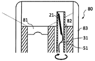
長尺部材31として、直径0.3mmのコバルトニッケル合金の単線の先端側を曲げ、屈曲部32を形成した。屈曲部より先端側の、内視鏡のレンズ面に面する位置に清掃部材21として、直径15μmのナイロン糸を、静電植毛により長尺部材の先端側に植えつけた。図16に示すように長尺部材のレンズに対向する側だけに清掃部材21を設けている。これにより、識別部が構成される。この構成ではレンズに対向する側の反対側は長尺部材の線材31が露出している。図17および図18に示すように、線材が内視鏡画像で見えれば、長尺部材を押し出してもレンズに対向しないと分かるので、図19に示すように、外筒51を捻って回転させる。図20に示すように、長尺部材が見えなくなり、すなわち清掃部材が内視鏡画像で見えるところで長尺部材を押し出せば、図21に示すように、長尺部材の屈曲部よりも先端側を内視鏡の中心側に復元させることができる。したがって図17に示すように内視鏡にフード83が付いた状態でも、清掃部材とフードを干渉させることなくレンズを清掃することができる。
図16~図21は実施例6に係る第2の清掃具の使用状態の先端部を示す図である。以下記載の条件以外は、実施例1に係る第1の清掃具と同様にして第2の清掃具を作製した。
長尺部材31として、直径0.3mmのコバルトニッケル合金の単線の先端側を曲げ、屈曲部32を形成した。屈曲部より先端側の、内視鏡のレンズ面に面する位置に清掃部材21として、直径15μmのナイロン糸を、静電植毛により長尺部材の先端側に植えつけた。図16に示すように長尺部材のレンズに対向する側だけに清掃部材21を設けている。これにより、識別部が構成される。この構成ではレンズに対向する側の反対側は長尺部材の線材31が露出している。図17および図18に示すように、線材が内視鏡画像で見えれば、長尺部材を押し出してもレンズに対向しないと分かるので、図19に示すように、外筒51を捻って回転させる。図20に示すように、長尺部材が見えなくなり、すなわち清掃部材が内視鏡画像で見えるところで長尺部材を押し出せば、図21に示すように、長尺部材の屈曲部よりも先端側を内視鏡の中心側に復元させることができる。したがって図17に示すように内視鏡にフード83が付いた状態でも、清掃部材とフードを干渉させることなくレンズを清掃することができる。
10 内視鏡用レンズ清掃具
21 清掃部材
31 長尺部材
32 屈曲部
41 操作ハンドル
51 外筒
80 内視鏡
81 内視鏡レンズ
82 処置具挿通チャンネル
83 内視鏡フード
90 内視鏡画像の枠
21 清掃部材
31 長尺部材
32 屈曲部
41 操作ハンドル
51 外筒
80 内視鏡
81 内視鏡レンズ
82 処置具挿通チャンネル
83 内視鏡フード
90 内視鏡画像の枠
Claims (20)
- トルクを伝達する弾性変形可能な長尺部材と、
長尺部材の先端部の外周面に固定されており、内視鏡のレンズを清掃する清掃部材を備え、
長尺部材は先端側に屈曲部を有し、
清掃部材が内視鏡のレンズ面と対向しており、
清掃部材は、当該長尺部材が内視鏡の処置具挿通チャンネルに挿通されて内視鏡先端から突出して、内視鏡のレンズ面側における清掃部材の包絡線が、前記内視鏡の軸方向と垂直な面に対して非平行である部分を有する内視鏡用レンズ清掃具。 - 前記包絡線が、前記内視鏡の軸方向と垂直な面に対して勾配を有する請求項1に記載の内視鏡用レンズ清掃具。
- 前記包絡線と、前記内視鏡の軸方向と垂直な面との距離が、長尺部材の先端側がより小さい請求項2に記載の内視鏡用レンズ清掃具。
- 前記清掃部材が先端に向かって、前記包絡線と、前記内視鏡の軸方向と垂直な面との距離が小さくなるテーパ形状である請求項1から3のいずれかに記載の内視鏡用レンズ清掃具。
- 前記長尺部材の屈曲部が、長尺部材の先端部がレンズ面に対して近づく方向に屈曲している請求項1から4のいずれかに記載の内視鏡用レンズ清掃具。
- 前記長尺部材の屈曲部が、長尺部材の先端部が前記内視鏡の軸方向と垂直な面に対して平行な方向に屈曲している請求項1から4のいずれかに記載の内視鏡用レンズ清掃具。
- 前記長尺部材および前記清掃部材を収納可能な樹脂製の長尺の外筒を備える請求項1から6のいずれかに記載の内視鏡用レンズ清掃具。
- 前記内視鏡用レンズ清掃具の先端が前記内視鏡の軸方向と垂直な面に対して離れていく方向に屈曲している請求項1から7のいずれかに記載の内視鏡用レンズ清掃具。
- トルクを伝達する弾性変形可能な長尺部材と、
長尺部材の先端部の外周面に固定されており、内視鏡のレンズを清掃する清掃部材と、
前記長尺部材と前記清掃部材を収納可能な外筒を備え、
長尺部材は清掃部材より基端側に屈曲部を有し、
清掃部材が内視鏡のレンズ面と対向している内視鏡用レンズ清掃具。 - 前記清掃部材は長尺部材の先端部の外周面を被覆するものである請求項1から9のいずれかに記載の内視鏡用レンズ清掃具。
- 前記長尺部材もしくは前記清掃部材に清掃部材の存在を識別できる識別部を備えた請求項9または10に記載の内視鏡用レンズ清掃具。
- 前記識別部は、長尺部材が内視鏡の処置具挿通チャンネルに挿通されて内視鏡先端から突出した際に、内視鏡のレンズ面に面する位置または、反対側の位置に位置する請求項11に記載の内視鏡用レンズ清掃具。
- 前記清掃部材が、長尺部材が内視鏡の処置具挿通チャンネルに挿通されて内視鏡先端から突出した際に、内視鏡のレンズ面に面する位置に設けられている請求項11に記載の内視鏡用レンズ清掃具。
- 前記清掃部材が、長尺部材が内視鏡の処置具挿通チャンネルに挿通されて内視鏡先端から突出した際に、内視鏡のレンズ面に面する位置にのみ設けられており、その反対側には設けられていない請求項11に記載の内視鏡用レンズ清掃具。
- 前記清掃部材の色が、長尺部材が内視鏡の処置具挿通チャンネルに挿通されて内視鏡先端から突出した際に、内視鏡のレンズ面に面する位置とその反対側の位置とで異なる請求項11から13に記載の内視鏡用レンズ清掃具。
- 前記長尺部材が中空のチューブ材であり、長尺部材の清掃部材が設けられた部分に開口部を有する請求項1から15のいずれかに記載の内視鏡用レンズ清掃具。
- 前記清掃部材の先端部に、内視鏡のレンズより硬度の低い柔軟部を有する請求項1から16のいずれかに記載の内視鏡用レンズ清掃具。
- 前記清掃部材がブラシである請求項1から17のいずれかに記載の内視鏡用レンズ清掃具。
- 前記清掃部材の材質がエラストマーである請求項1から18のいずれかに記載の内視鏡用レンズ清掃具。
- 前記清掃部材の材質が生分解性樹脂である請求項1から19のいずれかに記載の内視鏡用レンズ清掃具。
Applications Claiming Priority (4)
| Application Number | Priority Date | Filing Date | Title |
|---|---|---|---|
| JP2015136405A JP2018134120A (ja) | 2015-07-07 | 2015-07-07 | 内視鏡用レンズ清掃具 |
| JP2015-136405 | 2015-07-07 | ||
| JP2015-136404 | 2015-07-07 | ||
| JP2015136404A JP2018134119A (ja) | 2015-07-07 | 2015-07-07 | 内視鏡用レンズ清掃具 |
Publications (1)
| Publication Number | Publication Date |
|---|---|
| WO2017006684A1 true WO2017006684A1 (ja) | 2017-01-12 |
Family
ID=57685417
Family Applications (1)
| Application Number | Title | Priority Date | Filing Date |
|---|---|---|---|
| PCT/JP2016/066861 Ceased WO2017006684A1 (ja) | 2015-07-07 | 2016-06-07 | 内視鏡用レンズ清掃具 |
Country Status (1)
| Country | Link |
|---|---|
| WO (1) | WO2017006684A1 (ja) |
Cited By (43)
| Publication number | Priority date | Publication date | Assignee | Title |
|---|---|---|---|---|
| US9924979B2 (en) | 2014-09-09 | 2018-03-27 | Medos International Sarl | Proximal-end securement of a minimally invasive working channel |
| US9980737B2 (en) | 2014-08-04 | 2018-05-29 | Medos International Sarl | Flexible transport auger |
| US10111712B2 (en) | 2014-09-09 | 2018-10-30 | Medos International Sarl | Proximal-end securement of a minimally invasive working channel |
| US10264959B2 (en) | 2014-09-09 | 2019-04-23 | Medos International Sarl | Proximal-end securement of a minimally invasive working channel |
| US10299838B2 (en) | 2016-02-05 | 2019-05-28 | Medos International Sarl | Method and instruments for interbody fusion and posterior fixation through a single incision |
| WO2019226855A1 (en) * | 2018-05-23 | 2019-11-28 | Board Of Regents, The University Of Texas System | Devices, systems and methods for cleaning of elongated instrument surface |
| US10682130B2 (en) | 2015-09-04 | 2020-06-16 | Medos International Sarl | Surgical access port stabilization |
| US10786264B2 (en) | 2015-03-31 | 2020-09-29 | Medos International Sarl | Percutaneous disc clearing device |
| US10791918B1 (en) | 2019-10-04 | 2020-10-06 | ClearCam Inc. | Imaging element cleaning apparatus |
| US10959610B1 (en) | 2019-10-04 | 2021-03-30 | Clearcam Inc | Imaging element cleaning apparatus with structure-mandated cleaning member motion control |
| USRE48534E1 (en) | 2012-04-16 | 2021-04-27 | DePuy Synthes Products, Inc. | Detachable dilator blade |
| US10993609B1 (en) | 2021-01-23 | 2021-05-04 | ClearCam Inc. | Imaging element cleaning device with imaging device fitment adjustability |
| US11013399B1 (en) | 2020-01-27 | 2021-05-25 | Board Of Regents, The University Of Texas System | Wiper assembly for imaging element cleaning apparatus |
| US11013530B2 (en) | 2019-03-08 | 2021-05-25 | Medos International Sarl | Surface features for device retention |
| US11033179B1 (en) | 2020-06-12 | 2021-06-15 | ClearCam Inc. | Method for placement of an imaging element cleaning apparatus and obturator for enabling same |
| US11045324B2 (en) | 2006-12-08 | 2021-06-29 | DePuy Synthes Products, Inc. | Method of implanting a curable implant material |
| US11051862B2 (en) | 2001-11-03 | 2021-07-06 | DePuy Synthes Products, Inc. | Device for straightening and stabilizing the vertebral column |
| US11058291B2 (en) | 2018-11-29 | 2021-07-13 | Board Of Regents, The University Of Texas System | Devices, systems and methods for cleaning of elongated instrument surface |
| US11109940B1 (en) | 2021-02-09 | 2021-09-07 | ClearCam Inc. | Devices, apparatuses, systems and methods for facilitating cleaning of an imaging element of an imaging device |
| US11129727B2 (en) | 2019-03-29 | 2021-09-28 | Medos International Sari | Inflatable non-distracting intervertebral implants and related methods |
| US11134987B2 (en) | 2011-10-27 | 2021-10-05 | DePuy Synthes Products, Inc. | Method and devices for a sub-splenius/supra-levator scapulae surgical access technique |
| US11219439B2 (en) | 2012-09-26 | 2022-01-11 | DePuy Synthes Products, Inc. | NIR/RED light for lateral neuroprotection |
| US11241252B2 (en) | 2019-03-22 | 2022-02-08 | Medos International Sarl | Skin foundation access portal |
| US11375887B2 (en) | 2019-10-04 | 2022-07-05 | ClearCam Inc. | Imaging element cleaning apparatus |
| US11439380B2 (en) | 2015-09-04 | 2022-09-13 | Medos International Sarl | Surgical instrument connectors and related methods |
| US11559328B2 (en) | 2015-09-04 | 2023-01-24 | Medos International Sarl | Multi-shield spinal access system |
| US11660082B2 (en) | 2011-11-01 | 2023-05-30 | DePuy Synthes Products, Inc. | Dilation system |
| US11672562B2 (en) | 2015-09-04 | 2023-06-13 | Medos International Sarl | Multi-shield spinal access system |
| US11707189B1 (en) | 2022-02-10 | 2023-07-25 | ClearCam Inc. | Methods, devices and systems for cleaning an imaging element with a translatable cleaning element |
| US11737743B2 (en) | 2007-10-05 | 2023-08-29 | DePuy Synthes Products, Inc. | Dilation system and method of using the same |
| US11744447B2 (en) | 2015-09-04 | 2023-09-05 | Medos International | Surgical visualization systems and related methods |
| US11766309B2 (en) | 2021-03-09 | 2023-09-26 | ClearCam Inc. | Articles, kits and methods adapted for facilitating adjustability of operative apparatuses |
| US11771517B2 (en) | 2021-03-12 | 2023-10-03 | Medos International Sarl | Camera position indication systems and methods |
| US11813026B2 (en) | 2019-04-05 | 2023-11-14 | Medos International Sarl | Systems, devices, and methods for providing surgical trajectory guidance |
| US11998403B2 (en) | 2020-08-17 | 2024-06-04 | Covidien Lp | Endoscope cleaning device |
| US12150636B2 (en) | 2015-09-04 | 2024-11-26 | Medos International Sárl | Surgical instrument connectors and related methods |
| US12226568B2 (en) | 2020-06-05 | 2025-02-18 | Cook Medical Technologies Llc | Medical scopes for delivering therapeutic agents |
| CN120000129A (zh) * | 2025-02-20 | 2025-05-16 | 清华大学 | 内窥镜、内窥镜影像去遮挡方法及内窥镜系统 |
| US12318573B2 (en) | 2013-10-02 | 2025-06-03 | Cook Medical Technologies Llc | Therapeutic agents for delivery using a catheter and pressure source |
| US12426868B2 (en) | 2007-09-28 | 2025-09-30 | DePuy Synthes Products, Inc. | Balloon with shape control for spinal procedures |
| WO2025226448A1 (en) * | 2024-04-23 | 2025-10-30 | ClearCam, Inc. | Imaging element cleaning apparatus and calibration device useful with same |
| US12496429B2 (en) | 2022-10-18 | 2025-12-16 | Cook Medical Technologies Llc | Systems and methods for delivering pressurized fluid to a target site alone or in conjunction with therapeutic agents |
| US12543936B2 (en) | 2021-07-14 | 2026-02-10 | Cook Medical Technologies Llc | Systems and methods for preventing clogging of a delivery system |
Citations (8)
| Publication number | Priority date | Publication date | Assignee | Title |
|---|---|---|---|---|
| JPS57116201U (ja) * | 1981-01-08 | 1982-07-19 | ||
| JP2002523131A (ja) * | 1998-08-20 | 2002-07-30 | ノバファーム リサーチ (オーストラリア) プロプライアタリー リミティッド | 内視鏡洗浄装置 |
| JP2003199703A (ja) * | 2001-12-28 | 2003-07-15 | Olympus Optical Co Ltd | 内視鏡用シース |
| JP2010004938A (ja) * | 2008-06-24 | 2010-01-14 | National Cancer Center-Japan | 内視鏡用洗浄具 |
| JP2012110681A (ja) * | 2010-11-23 | 2012-06-14 | Tyco Healthcare Group Lp | 引き込み可能な内視鏡クリーナを含むポートデバイス |
| US20130305469A1 (en) * | 2012-02-29 | 2013-11-21 | Jose Rodriguez Sanjuan | Method and apparatus for cleaning an endoscope |
| JP2014204843A (ja) * | 2013-04-12 | 2014-10-30 | 株式会社村田製作所 | 内視鏡用清掃具、内視鏡システム |
| WO2016111373A1 (ja) * | 2015-01-09 | 2016-07-14 | 東レ・メディカル株式会社 | 内視鏡レンズ用清拭デバイス及びこの清拭デバイスを備えた内視鏡 |
-
2016
- 2016-06-07 WO PCT/JP2016/066861 patent/WO2017006684A1/ja not_active Ceased
Patent Citations (8)
| Publication number | Priority date | Publication date | Assignee | Title |
|---|---|---|---|---|
| JPS57116201U (ja) * | 1981-01-08 | 1982-07-19 | ||
| JP2002523131A (ja) * | 1998-08-20 | 2002-07-30 | ノバファーム リサーチ (オーストラリア) プロプライアタリー リミティッド | 内視鏡洗浄装置 |
| JP2003199703A (ja) * | 2001-12-28 | 2003-07-15 | Olympus Optical Co Ltd | 内視鏡用シース |
| JP2010004938A (ja) * | 2008-06-24 | 2010-01-14 | National Cancer Center-Japan | 内視鏡用洗浄具 |
| JP2012110681A (ja) * | 2010-11-23 | 2012-06-14 | Tyco Healthcare Group Lp | 引き込み可能な内視鏡クリーナを含むポートデバイス |
| US20130305469A1 (en) * | 2012-02-29 | 2013-11-21 | Jose Rodriguez Sanjuan | Method and apparatus for cleaning an endoscope |
| JP2014204843A (ja) * | 2013-04-12 | 2014-10-30 | 株式会社村田製作所 | 内視鏡用清掃具、内視鏡システム |
| WO2016111373A1 (ja) * | 2015-01-09 | 2016-07-14 | 東レ・メディカル株式会社 | 内視鏡レンズ用清拭デバイス及びこの清拭デバイスを備えた内視鏡 |
Cited By (97)
| Publication number | Priority date | Publication date | Assignee | Title |
|---|---|---|---|---|
| US11051862B2 (en) | 2001-11-03 | 2021-07-06 | DePuy Synthes Products, Inc. | Device for straightening and stabilizing the vertebral column |
| US11045324B2 (en) | 2006-12-08 | 2021-06-29 | DePuy Synthes Products, Inc. | Method of implanting a curable implant material |
| US12426868B2 (en) | 2007-09-28 | 2025-09-30 | DePuy Synthes Products, Inc. | Balloon with shape control for spinal procedures |
| US11737743B2 (en) | 2007-10-05 | 2023-08-29 | DePuy Synthes Products, Inc. | Dilation system and method of using the same |
| US11278323B2 (en) | 2011-10-27 | 2022-03-22 | DePuy Synthes Products, Inc. | Method and devices for a sub-splenius/supra-levator scapulae surgical access technique |
| US11937797B2 (en) | 2011-10-27 | 2024-03-26 | DePuy Synthes Products, Inc. | Method and devices for a sub-splenius/supra-levator scapulae surgical access technique |
| US11234736B2 (en) | 2011-10-27 | 2022-02-01 | DePuy Synthes Products, Inc. | Method and devices for a sub-splenius/supra-levator scapulae surgical access technique |
| US11241255B2 (en) | 2011-10-27 | 2022-02-08 | DePuy Synthes Products, Inc. | Method and devices for a sub-splenius/supra-levator scapulae surgical access technique |
| US11134987B2 (en) | 2011-10-27 | 2021-10-05 | DePuy Synthes Products, Inc. | Method and devices for a sub-splenius/supra-levator scapulae surgical access technique |
| US11911017B2 (en) | 2011-10-27 | 2024-02-27 | DePuy Synthes Products, Inc. | Method and devices for a sub-splenius/supra-levator scapulae surgical access technique |
| US11660082B2 (en) | 2011-11-01 | 2023-05-30 | DePuy Synthes Products, Inc. | Dilation system |
| USRE48534E1 (en) | 2012-04-16 | 2021-04-27 | DePuy Synthes Products, Inc. | Detachable dilator blade |
| US11219439B2 (en) | 2012-09-26 | 2022-01-11 | DePuy Synthes Products, Inc. | NIR/RED light for lateral neuroprotection |
| US11559295B2 (en) | 2012-09-26 | 2023-01-24 | DePuy Synthes Products, Inc. | NIR/red light for lateral neuroprotection |
| US12318573B2 (en) | 2013-10-02 | 2025-06-03 | Cook Medical Technologies Llc | Therapeutic agents for delivery using a catheter and pressure source |
| US10863994B2 (en) | 2014-08-04 | 2020-12-15 | Medos International Sàrl | Flexible transport auger |
| US12433610B2 (en) | 2014-08-04 | 2025-10-07 | Medos International Sarl | Flexible transport auger |
| US11712252B2 (en) | 2014-08-04 | 2023-08-01 | Medos International Sarl | Flexible transport auger |
| US9980737B2 (en) | 2014-08-04 | 2018-05-29 | Medos International Sarl | Flexible transport auger |
| US9924979B2 (en) | 2014-09-09 | 2018-03-27 | Medos International Sarl | Proximal-end securement of a minimally invasive working channel |
| US10264959B2 (en) | 2014-09-09 | 2019-04-23 | Medos International Sarl | Proximal-end securement of a minimally invasive working channel |
| US10786330B2 (en) | 2014-09-09 | 2020-09-29 | Medos International Sarl | Proximal-end securement of a minimally invasive working channel |
| US10111712B2 (en) | 2014-09-09 | 2018-10-30 | Medos International Sarl | Proximal-end securement of a minimally invasive working channel |
| US11213196B2 (en) | 2014-09-09 | 2022-01-04 | Medos International Sarl | Proximal-end securement of a minimally invasive working channel |
| US10786264B2 (en) | 2015-03-31 | 2020-09-29 | Medos International Sarl | Percutaneous disc clearing device |
| US11464523B2 (en) | 2015-03-31 | 2022-10-11 | Medos International Sarl | Percutaneous disc clearing device |
| US12042158B2 (en) | 2015-03-31 | 2024-07-23 | Medos International Sarl | Percutaneous disc clearing device |
| US12343021B2 (en) | 2015-03-31 | 2025-07-01 | Medos International Sàrl | Percutaneous disc clearing device |
| US11950766B2 (en) | 2015-09-04 | 2024-04-09 | Medos International Sàrl | Surgical visualization systems and related methods |
| US11801070B2 (en) | 2015-09-04 | 2023-10-31 | Medos International Sarl | Surgical access port stabilization |
| US12507880B2 (en) | 2015-09-04 | 2025-12-30 | Medos International Sàrl | Devices and methods for providing surgical access |
| US12496093B2 (en) | 2015-09-04 | 2025-12-16 | Medos International Sàrl | Multi-shield spinal access system |
| US12402909B2 (en) | 2015-09-04 | 2025-09-02 | Medos International Sàrl | Multi-shield spinal access system |
| US12383302B2 (en) | 2015-09-04 | 2025-08-12 | Medos International Sàrl | Surgical visualization systems and related methods |
| US10682130B2 (en) | 2015-09-04 | 2020-06-16 | Medos International Sarl | Surgical access port stabilization |
| US10758220B2 (en) | 2015-09-04 | 2020-09-01 | Medos International Sarl | Devices and methods for providing surgical access |
| US12193704B2 (en) | 2015-09-04 | 2025-01-14 | Medos International Sàrl | Multi-shield spinal access system |
| US12150636B2 (en) | 2015-09-04 | 2024-11-26 | Medos International Sárl | Surgical instrument connectors and related methods |
| US10779810B2 (en) | 2015-09-04 | 2020-09-22 | Medos International Sarl | Devices and methods for surgical retraction |
| US10869659B2 (en) | 2015-09-04 | 2020-12-22 | Medos International Sarl | Surgical instrument connectors and related methods |
| US11331090B2 (en) | 2015-09-04 | 2022-05-17 | Medos International Sarl | Surgical visualization systems and related methods |
| US11344190B2 (en) | 2015-09-04 | 2022-05-31 | Medos International Sarl | Surgical visualization systems and related methods |
| US10874425B2 (en) | 2015-09-04 | 2020-12-29 | Medos International Sarl | Multi-shield spinal access system |
| US11883064B2 (en) | 2015-09-04 | 2024-01-30 | Medos International Sarl | Multi-shield spinal access system |
| US11439380B2 (en) | 2015-09-04 | 2022-09-13 | Medos International Sarl | Surgical instrument connectors and related methods |
| US11000312B2 (en) | 2015-09-04 | 2021-05-11 | Medos International Sarl | Multi-shield spinal access system |
| US11806043B2 (en) | 2015-09-04 | 2023-11-07 | Medos International Sarl | Devices and methods for providing surgical access |
| US11559328B2 (en) | 2015-09-04 | 2023-01-24 | Medos International Sarl | Multi-shield spinal access system |
| US10987129B2 (en) | 2015-09-04 | 2021-04-27 | Medos International Sarl | Multi-shield spinal access system |
| US11672562B2 (en) | 2015-09-04 | 2023-06-13 | Medos International Sarl | Multi-shield spinal access system |
| US11793546B2 (en) | 2015-09-04 | 2023-10-24 | Medos International Sarl | Surgical visualization systems and related methods |
| US11744447B2 (en) | 2015-09-04 | 2023-09-05 | Medos International | Surgical visualization systems and related methods |
| US11712264B2 (en) | 2015-09-04 | 2023-08-01 | Medos International Sarl | Multi-shield spinal access system |
| US10299838B2 (en) | 2016-02-05 | 2019-05-28 | Medos International Sarl | Method and instruments for interbody fusion and posterior fixation through a single incision |
| US11020153B2 (en) | 2016-02-05 | 2021-06-01 | Medos International Sarl | Method and instruments for interbody fusion and posterior fixation through a single incision |
| US12144527B2 (en) | 2016-02-05 | 2024-11-19 | Medos International Sarl | Method and instruments for interbody fusion and posterior fixation through a single incision |
| WO2019226855A1 (en) * | 2018-05-23 | 2019-11-28 | Board Of Regents, The University Of Texas System | Devices, systems and methods for cleaning of elongated instrument surface |
| US11877729B2 (en) | 2018-11-29 | 2024-01-23 | Board Of Regents, The University Of Texas System | Devices, systems and methods for cleaning of elongated instrument surface |
| US11058291B2 (en) | 2018-11-29 | 2021-07-13 | Board Of Regents, The University Of Texas System | Devices, systems and methods for cleaning of elongated instrument surface |
| US12239296B2 (en) | 2018-11-29 | 2025-03-04 | Board Of Regents, The University Of Texas System | Devices, systems and methods for cleaning of elongated instrument surface |
| EP3886674A4 (en) * | 2018-11-29 | 2022-08-03 | Board of Regents, The University of Texas System | DEVICES, SYSTEMS AND METHODS FOR CLEANING AN OBTAINED INSTRUMENT SURFACE |
| US11013530B2 (en) | 2019-03-08 | 2021-05-25 | Medos International Sarl | Surface features for device retention |
| US12089873B2 (en) | 2019-03-22 | 2024-09-17 | Medos International Sàrl | Skin foundation access portal |
| US11241252B2 (en) | 2019-03-22 | 2022-02-08 | Medos International Sarl | Skin foundation access portal |
| US11129727B2 (en) | 2019-03-29 | 2021-09-28 | Medos International Sari | Inflatable non-distracting intervertebral implants and related methods |
| US11813026B2 (en) | 2019-04-05 | 2023-11-14 | Medos International Sarl | Systems, devices, and methods for providing surgical trajectory guidance |
| US11707187B2 (en) | 2019-10-04 | 2023-07-25 | ClearCam Inc. | Imaging element cleaning apparatus |
| US11707188B2 (en) | 2019-10-04 | 2023-07-25 | ClearCam Inc. | Imaging element cleaning apparatus with structure-mandated cleaning member motion control |
| US10932661B1 (en) | 2019-10-04 | 2021-03-02 | ClearCam Inc. | Imaging element cleaning apparatus |
| US11375887B2 (en) | 2019-10-04 | 2022-07-05 | ClearCam Inc. | Imaging element cleaning apparatus |
| US11284789B2 (en) | 2019-10-04 | 2022-03-29 | ClearCam, Inc. | Imaging element cleaning apparatus with structure-mandated cleaning member motion control |
| US10791918B1 (en) | 2019-10-04 | 2020-10-06 | ClearCam Inc. | Imaging element cleaning apparatus |
| US10959610B1 (en) | 2019-10-04 | 2021-03-30 | Clearcam Inc | Imaging element cleaning apparatus with structure-mandated cleaning member motion control |
| US12161303B2 (en) | 2019-10-04 | 2024-12-10 | ClearCam, Inc. | Imaging element cleaning apparatus with structure-mandated cleaning member motion control |
| US11172813B2 (en) | 2020-01-27 | 2021-11-16 | Board Of Regents, The University Of Texas System | Wiper assembly for imaging element cleaning apparatus |
| US11737661B2 (en) | 2020-01-27 | 2023-08-29 | Board Of Regents, The University Of Texas System | Wiper assembly for imaging element cleaning apparatus |
| US11013399B1 (en) | 2020-01-27 | 2021-05-25 | Board Of Regents, The University Of Texas System | Wiper assembly for imaging element cleaning apparatus |
| WO2021154633A3 (en) * | 2020-01-27 | 2021-10-28 | Board Of Regents, The University Of Texas System | Wiper assembly for imaging element cleaning apparatus |
| US12226568B2 (en) | 2020-06-05 | 2025-02-18 | Cook Medical Technologies Llc | Medical scopes for delivering therapeutic agents |
| US12171411B2 (en) | 2020-06-12 | 2024-12-24 | ClearCam, Inc. | Method for placement of an imaging element cleaning apparatus and obturator for enabling same |
| US11033179B1 (en) | 2020-06-12 | 2021-06-15 | ClearCam Inc. | Method for placement of an imaging element cleaning apparatus and obturator for enabling same |
| US11717145B2 (en) | 2020-06-12 | 2023-08-08 | ClearCam Inc. | Method for placement of an imaging element cleaning apparatus and obturator for enabling same |
| US11723527B2 (en) | 2020-06-12 | 2023-08-15 | ClearCam Inc. | Method for placement of an imaging element cleaning apparatus and obturator for enabling same |
| US11998403B2 (en) | 2020-08-17 | 2024-06-04 | Covidien Lp | Endoscope cleaning device |
| US10993609B1 (en) | 2021-01-23 | 2021-05-04 | ClearCam Inc. | Imaging element cleaning device with imaging device fitment adjustability |
| US11819197B2 (en) | 2021-01-23 | 2023-11-21 | ClearCam, Inc. | Imaging element cleaning device with imaging device fitment adjustability |
| US11857382B2 (en) | 2021-02-09 | 2024-01-02 | ClearCam, Inc. | Devices, apparatuses, systems and methods for facilitating cleaning of an imaging element of an imaging device |
| US11109940B1 (en) | 2021-02-09 | 2021-09-07 | ClearCam Inc. | Devices, apparatuses, systems and methods for facilitating cleaning of an imaging element of an imaging device |
| US12285302B2 (en) | 2021-02-09 | 2025-04-29 | ClearCam, Inc. | Devices, apparatuses, systems and methods for facilitating cleaning of an imaging element of an imaging device |
| US11766309B2 (en) | 2021-03-09 | 2023-09-26 | ClearCam Inc. | Articles, kits and methods adapted for facilitating adjustability of operative apparatuses |
| US11771517B2 (en) | 2021-03-12 | 2023-10-03 | Medos International Sarl | Camera position indication systems and methods |
| US12303341B2 (en) | 2021-03-12 | 2025-05-20 | Medos International Srl | Camera position indication systems and methods |
| US12543936B2 (en) | 2021-07-14 | 2026-02-10 | Cook Medical Technologies Llc | Systems and methods for preventing clogging of a delivery system |
| US11707189B1 (en) | 2022-02-10 | 2023-07-25 | ClearCam Inc. | Methods, devices and systems for cleaning an imaging element with a translatable cleaning element |
| US12496429B2 (en) | 2022-10-18 | 2025-12-16 | Cook Medical Technologies Llc | Systems and methods for delivering pressurized fluid to a target site alone or in conjunction with therapeutic agents |
| WO2025226448A1 (en) * | 2024-04-23 | 2025-10-30 | ClearCam, Inc. | Imaging element cleaning apparatus and calibration device useful with same |
| CN120000129A (zh) * | 2025-02-20 | 2025-05-16 | 清华大学 | 内窥镜、内窥镜影像去遮挡方法及内窥镜系统 |
Similar Documents
| Publication | Publication Date | Title |
|---|---|---|
| JP5166133B2 (ja) | 内視鏡 | |
| US9486129B2 (en) | Method and apparatus for cleaning an endoscope | |
| CN106687055B (zh) | 内窥镜用处置器具、处置器具单元及处置系统 | |
| US10820785B2 (en) | Cover removal tool for endoscope | |
| JP6157791B2 (ja) | 内視鏡 | |
| EP3808246A1 (en) | Rigid endoscope cover and endoscope unit | |
| US20180249903A1 (en) | Endoscope lumen internal cleaner and methods of use | |
| EP1829474B1 (en) | Washing brush for cleaning a conduit | |
| JP5839166B2 (ja) | 医療用バスケット型処置器具 | |
| WO2016092979A1 (ja) | 補助具及び内視鏡システム | |
| JP2025516556A (ja) | 内視鏡デバイスを乾燥させるためのシステム及び方法 | |
| JP6756055B2 (ja) | 内視鏡のフードの取り外し治具、及びフードとフードの取り外し治具のセット | |
| TWI745954B (zh) | 臟器吸引把持具 | |
| JP2015213840A (ja) | 医療用バスケット型処置器具 | |
| JP2018134119A (ja) | 内視鏡用レンズ清掃具 | |
| JP6300274B2 (ja) | 内視鏡レンズ用清拭デバイスおよび該清拭デバイスを備えた内視鏡 | |
| US10779906B2 (en) | Cleaning device with microfiber tails | |
| JP7795226B2 (ja) | 内視鏡デバイスの取り外しシステム及び方法 | |
| JP5390150B2 (ja) | 補助具及び内視鏡システム | |
| JP5305859B2 (ja) | 内視鏡システム | |
| WO2022013942A1 (ja) | 内視鏡の管路洗浄具、内視鏡システム | |
| JP5634928B2 (ja) | 内視鏡 | |
| JP2018134120A (ja) | 内視鏡用レンズ清掃具 | |
| CN102238896A (zh) | 洗涤刷旋转机构 | |
| JP6065723B2 (ja) | 内視鏡用清掃具、内視鏡システム |
Legal Events
| Date | Code | Title | Description |
|---|---|---|---|
| 121 | Ep: the epo has been informed by wipo that ep was designated in this application |
Ref document number: 16821155 Country of ref document: EP Kind code of ref document: A1 |
|
| NENP | Non-entry into the national phase |
Ref country code: DE |
|
| NENP | Non-entry into the national phase |
Ref country code: JP |
|
| 122 | Ep: pct application non-entry in european phase |
Ref document number: 16821155 Country of ref document: EP Kind code of ref document: A1 |