WO2017006530A1 - 積層塗膜及び塗装物 - Google Patents
積層塗膜及び塗装物 Download PDFInfo
- Publication number
- WO2017006530A1 WO2017006530A1 PCT/JP2016/003019 JP2016003019W WO2017006530A1 WO 2017006530 A1 WO2017006530 A1 WO 2017006530A1 JP 2016003019 W JP2016003019 W JP 2016003019W WO 2017006530 A1 WO2017006530 A1 WO 2017006530A1
- Authority
- WO
- WIPO (PCT)
- Prior art keywords
- containing layer
- glittering
- coating film
- less
- glittering material
- Prior art date
Links
- 239000011248 coating agent Substances 0.000 title claims abstract description 64
- 238000000576 coating method Methods 0.000 title claims abstract description 64
- 239000000463 material Substances 0.000 claims abstract description 200
- 229910052782 aluminium Inorganic materials 0.000 claims description 32
- XAGFODPZIPBFFR-UHFFFAOYSA-N aluminium Chemical compound [Al] XAGFODPZIPBFFR-UHFFFAOYSA-N 0.000 claims description 32
- 238000004040 coloring Methods 0.000 claims description 28
- 239000000049 pigment Substances 0.000 description 42
- 239000002245 particle Substances 0.000 description 21
- 239000006229 carbon black Substances 0.000 description 13
- 239000003973 paint Substances 0.000 description 11
- 229910052751 metal Inorganic materials 0.000 description 10
- 239000002184 metal Substances 0.000 description 10
- 229920005989 resin Polymers 0.000 description 8
- 239000011347 resin Substances 0.000 description 8
- 239000003086 colorant Substances 0.000 description 7
- 229910000831 Steel Inorganic materials 0.000 description 5
- 238000004070 electrodeposition Methods 0.000 description 5
- 230000001788 irregular Effects 0.000 description 5
- 239000001054 red pigment Substances 0.000 description 5
- 239000010959 steel Substances 0.000 description 5
- 239000008199 coating composition Substances 0.000 description 4
- 230000007423 decrease Effects 0.000 description 4
- ZZSIDSMUTXFKNS-UHFFFAOYSA-N perylene red Chemical compound CC(C)C1=CC=CC(C(C)C)=C1N(C(=O)C=1C2=C3C4=C(OC=5C=CC=CC=5)C=1)C(=O)C2=CC(OC=1C=CC=CC=1)=C3C(C(OC=1C=CC=CC=1)=CC1=C2C(C(N(C=3C(=CC=CC=3C(C)C)C(C)C)C1=O)=O)=C1)=C2C4=C1OC1=CC=CC=C1 ZZSIDSMUTXFKNS-UHFFFAOYSA-N 0.000 description 4
- 230000003746 surface roughness Effects 0.000 description 4
- 238000009826 distribution Methods 0.000 description 3
- 230000000704 physical effect Effects 0.000 description 3
- 239000007787 solid Substances 0.000 description 3
- 239000000758 substrate Substances 0.000 description 3
- 238000010521 absorption reaction Methods 0.000 description 2
- 239000002253 acid Substances 0.000 description 2
- 125000002091 cationic group Chemical group 0.000 description 2
- 230000000694 effects Effects 0.000 description 2
- 238000010030 laminating Methods 0.000 description 2
- 230000031700 light absorption Effects 0.000 description 2
- 238000004519 manufacturing process Methods 0.000 description 2
- 238000002156 mixing Methods 0.000 description 2
- 238000010298 pulverizing process Methods 0.000 description 2
- FWLHAQYOFMQTHQ-UHFFFAOYSA-N 2-N-[8-[[8-(4-aminoanilino)-10-phenylphenazin-10-ium-2-yl]amino]-10-phenylphenazin-10-ium-2-yl]-8-N,10-diphenylphenazin-10-ium-2,8-diamine hydroxy-oxido-dioxochromium Chemical compound O[Cr]([O-])(=O)=O.O[Cr]([O-])(=O)=O.O[Cr]([O-])(=O)=O.Nc1ccc(Nc2ccc3nc4ccc(Nc5ccc6nc7ccc(Nc8ccc9nc%10ccc(Nc%11ccccc%11)cc%10[n+](-c%10ccccc%10)c9c8)cc7[n+](-c7ccccc7)c6c5)cc4[n+](-c4ccccc4)c3c2)cc1 FWLHAQYOFMQTHQ-UHFFFAOYSA-N 0.000 description 1
- 239000004925 Acrylic resin Substances 0.000 description 1
- 229920000178 Acrylic resin Polymers 0.000 description 1
- 239000004593 Epoxy Substances 0.000 description 1
- NIPNSKYNPDTRPC-UHFFFAOYSA-N N-[2-oxo-2-(2,4,6,7-tetrahydrotriazolo[4,5-c]pyridin-5-yl)ethyl]-2-[[3-(trifluoromethoxy)phenyl]methylamino]pyrimidine-5-carboxamide Chemical compound O=C(CNC(=O)C=1C=NC(=NC=1)NCC1=CC(=CC=C1)OC(F)(F)F)N1CC2=C(CC1)NN=N2 NIPNSKYNPDTRPC-UHFFFAOYSA-N 0.000 description 1
- MZZSDCJQCLYLLL-UHFFFAOYSA-N Secalonsaeure A Natural products COC(=O)C12OC3C(CC1=C(O)CC(C)C2O)C(=CC=C3c4ccc(O)c5C(=O)C6=C(O)CC(C)C(O)C6(Oc45)C(=O)OC)O MZZSDCJQCLYLLL-UHFFFAOYSA-N 0.000 description 1
- GLLRIXZGBQOFLM-UHFFFAOYSA-N Xanthorin Natural products C1=C(C)C=C2C(=O)C3=C(O)C(OC)=CC(O)=C3C(=O)C2=C1O GLLRIXZGBQOFLM-UHFFFAOYSA-N 0.000 description 1
- NIXOWILDQLNWCW-UHFFFAOYSA-N acrylic acid group Chemical group C(C=C)(=O)O NIXOWILDQLNWCW-UHFFFAOYSA-N 0.000 description 1
- 238000000149 argon plasma sintering Methods 0.000 description 1
- 239000011324 bead Substances 0.000 description 1
- 238000005260 corrosion Methods 0.000 description 1
- 230000007797 corrosion Effects 0.000 description 1
- 230000003247 decreasing effect Effects 0.000 description 1
- 238000011156 evaluation Methods 0.000 description 1
- 238000001704 evaporation Methods 0.000 description 1
- 230000008020 evaporation Effects 0.000 description 1
- 239000011888 foil Substances 0.000 description 1
- 239000011521 glass Substances 0.000 description 1
- 238000000227 grinding Methods 0.000 description 1
- 239000002932 luster Substances 0.000 description 1
- 230000003287 optical effect Effects 0.000 description 1
- 125000002080 perylenyl group Chemical group C1(=CC=C2C=CC=C3C4=CC=CC5=CC=CC(C1=C23)=C45)* 0.000 description 1
- CSHWQDPOILHKBI-UHFFFAOYSA-N peryrene Natural products C1=CC(C2=CC=CC=3C2=C2C=CC=3)=C3C2=CC=CC3=C1 CSHWQDPOILHKBI-UHFFFAOYSA-N 0.000 description 1
- 229920000767 polyaniline Polymers 0.000 description 1
- 229920001225 polyester resin Polymers 0.000 description 1
- 239000000843 powder Substances 0.000 description 1
- 239000002904 solvent Substances 0.000 description 1
- 238000001238 wet grinding Methods 0.000 description 1
Images


Classifications
-
- B—PERFORMING OPERATIONS; TRANSPORTING
- B32—LAYERED PRODUCTS
- B32B—LAYERED PRODUCTS, i.e. PRODUCTS BUILT-UP OF STRATA OF FLAT OR NON-FLAT, e.g. CELLULAR OR HONEYCOMB, FORM
- B32B15/00—Layered products comprising a layer of metal
- B32B15/04—Layered products comprising a layer of metal comprising metal as the main or only constituent of a layer, which is next to another layer of the same or of a different material
- B32B15/08—Layered products comprising a layer of metal comprising metal as the main or only constituent of a layer, which is next to another layer of the same or of a different material of synthetic resin
- B32B15/082—Layered products comprising a layer of metal comprising metal as the main or only constituent of a layer, which is next to another layer of the same or of a different material of synthetic resin comprising vinyl resins; comprising acrylic resins
-
- B—PERFORMING OPERATIONS; TRANSPORTING
- B05—SPRAYING OR ATOMISING IN GENERAL; APPLYING FLUENT MATERIALS TO SURFACES, IN GENERAL
- B05D—PROCESSES FOR APPLYING FLUENT MATERIALS TO SURFACES, IN GENERAL
- B05D1/00—Processes for applying liquids or other fluent materials
- B05D1/36—Successively applying liquids or other fluent materials, e.g. without intermediate treatment
-
- B—PERFORMING OPERATIONS; TRANSPORTING
- B05—SPRAYING OR ATOMISING IN GENERAL; APPLYING FLUENT MATERIALS TO SURFACES, IN GENERAL
- B05D—PROCESSES FOR APPLYING FLUENT MATERIALS TO SURFACES, IN GENERAL
- B05D5/00—Processes for applying liquids or other fluent materials to surfaces to obtain special surface effects, finishes or structures
- B05D5/06—Processes for applying liquids or other fluent materials to surfaces to obtain special surface effects, finishes or structures to obtain multicolour or other optical effects
-
- B—PERFORMING OPERATIONS; TRANSPORTING
- B05—SPRAYING OR ATOMISING IN GENERAL; APPLYING FLUENT MATERIALS TO SURFACES, IN GENERAL
- B05D—PROCESSES FOR APPLYING FLUENT MATERIALS TO SURFACES, IN GENERAL
- B05D7/00—Processes, other than flocking, specially adapted for applying liquids or other fluent materials to particular surfaces or for applying particular liquids or other fluent materials
- B05D7/14—Processes, other than flocking, specially adapted for applying liquids or other fluent materials to particular surfaces or for applying particular liquids or other fluent materials to metal, e.g. car bodies
- B05D7/16—Processes, other than flocking, specially adapted for applying liquids or other fluent materials to particular surfaces or for applying particular liquids or other fluent materials to metal, e.g. car bodies using synthetic lacquers or varnishes
-
- B—PERFORMING OPERATIONS; TRANSPORTING
- B05—SPRAYING OR ATOMISING IN GENERAL; APPLYING FLUENT MATERIALS TO SURFACES, IN GENERAL
- B05D—PROCESSES FOR APPLYING FLUENT MATERIALS TO SURFACES, IN GENERAL
- B05D7/00—Processes, other than flocking, specially adapted for applying liquids or other fluent materials to particular surfaces or for applying particular liquids or other fluent materials
- B05D7/50—Multilayers
- B05D7/56—Three layers or more
- B05D7/57—Three layers or more the last layer being a clear coat
- B05D7/572—Three layers or more the last layer being a clear coat all layers being cured or baked together
-
- B—PERFORMING OPERATIONS; TRANSPORTING
- B32—LAYERED PRODUCTS
- B32B—LAYERED PRODUCTS, i.e. PRODUCTS BUILT-UP OF STRATA OF FLAT OR NON-FLAT, e.g. CELLULAR OR HONEYCOMB, FORM
- B32B15/00—Layered products comprising a layer of metal
- B32B15/01—Layered products comprising a layer of metal all layers being exclusively metallic
- B32B15/016—Layered products comprising a layer of metal all layers being exclusively metallic all layers being formed of aluminium or aluminium alloys
-
- B—PERFORMING OPERATIONS; TRANSPORTING
- B32—LAYERED PRODUCTS
- B32B—LAYERED PRODUCTS, i.e. PRODUCTS BUILT-UP OF STRATA OF FLAT OR NON-FLAT, e.g. CELLULAR OR HONEYCOMB, FORM
- B32B15/00—Layered products comprising a layer of metal
- B32B15/04—Layered products comprising a layer of metal comprising metal as the main or only constituent of a layer, which is next to another layer of the same or of a different material
- B32B15/08—Layered products comprising a layer of metal comprising metal as the main or only constituent of a layer, which is next to another layer of the same or of a different material of synthetic resin
- B32B15/09—Layered products comprising a layer of metal comprising metal as the main or only constituent of a layer, which is next to another layer of the same or of a different material of synthetic resin comprising polyesters
-
- B—PERFORMING OPERATIONS; TRANSPORTING
- B32—LAYERED PRODUCTS
- B32B—LAYERED PRODUCTS, i.e. PRODUCTS BUILT-UP OF STRATA OF FLAT OR NON-FLAT, e.g. CELLULAR OR HONEYCOMB, FORM
- B32B27/00—Layered products comprising a layer of synthetic resin
- B32B27/18—Layered products comprising a layer of synthetic resin characterised by the use of special additives
- B32B27/20—Layered products comprising a layer of synthetic resin characterised by the use of special additives using fillers, pigments, thixotroping agents
-
- B—PERFORMING OPERATIONS; TRANSPORTING
- B05—SPRAYING OR ATOMISING IN GENERAL; APPLYING FLUENT MATERIALS TO SURFACES, IN GENERAL
- B05D—PROCESSES FOR APPLYING FLUENT MATERIALS TO SURFACES, IN GENERAL
- B05D2202/00—Metallic substrate
- B05D2202/10—Metallic substrate based on Fe
Definitions
- the present invention relates to a laminated coating film and a painted product.
- a plurality of coating films are stacked on the surface of a base material such as a car body or a car part to protect the base material and improve the appearance.
- a dark paint containing a dark pigment carbon black
- a metallic paint containing scaly aluminum pigment is applied, and further a clear paint is applied.
- Patent Document 2 describes a metallic coating composition containing three types of aluminum flake pigments A to C having different average particle diameters D50 and average thicknesses.
- the aluminum flake pigment A has an average particle diameter D50 of 13 to 40 ⁇ m and an average thickness of 0.5 to 2.5 ⁇ m.
- the aluminum flake pigment B has an average particle diameter D50 of 13 to 40 ⁇ m and an average thickness of 0.01 to 0.5 ⁇ m.
- the aluminum flake pigment C has an average particle diameter D50 of 4 to 13 ⁇ m and an average thickness of 0.01 to 1.3 ⁇ m.
- Aluminum flake pigments A to C have a solid content mass ratio of A / B of 10/90 to 90/10, (A + B) / C of 90/10 to 30/70, and resin solid content of 100 parts by mass.
- the amount of (A + B + C) is 5 to 50 parts by mass in terms of solid content.
- Patent Document 3 describes that a paint containing a flat glitter material made of aluminum is applied to a resin base material to obtain a glitter coating film having glitter and electromagnetic wave transparency.
- the glitter material is oriented so that its plane is along the surface of the coating film, and the average number of overlapping layers y, which is the average number of glitter materials intersecting with one orthogonal line orthogonal to the coating film surface, and the same orthogonal line.
- the average distance between the bright materials x which is the average of the distances between the intersecting bright materials on the orthogonal line, satisfies a predetermined relational expression.
- FF property flip-flop property
- FI flip index
- the glittering material for example, aluminum flakes
- the scattered light by the glittering material is certainly reduced and the specular reflection light becomes stronger.
- the brightness value at the highlight is increased and the brightness value at the shade is decreased, so that the FI value is increased.
- the specular reflection of the glittering material-containing layer becomes too strong due to control of the orientation of the glittering material, the reflection of the light source occurs like a specular reflection, or only part of the regular reflection of light is bright. (It looks shining whitish).
- the FI value represents the intensity of light in the vicinity of the regular reflection direction with respect to the lightness in the shade
- a low lightness in the vicinity of the regular reflection direction means that the FI value is also small.
- the scattering of light by the glittering material is increased in order to increase the lightness in the vicinity of the regular reflection direction, the lightness is also increased in the shade at the same time, and an outstanding FF property cannot be obtained.
- an object of the present invention is to improve the FF property and enhance the metal texture in metallic coating.
- the specular reflection characteristics by the glitter material are controlled by the area occupation ratio of the glitter material in the glitter material-containing layer, and the scattered light from the glitter material is absorbed by the coloring material and the colored underlayer of the glitter material. .
- the laminated coating film disclosed herein includes a colored foundation layer containing a coloring material formed directly or indirectly on the surface of an object to be coated, and a flake-like glittering material and a coloring material superimposed on the colored foundation layer.
- the thickness of the glittering material-containing layer is 1.5 ⁇ m or more and 6 ⁇ m or less,
- the area occupancy occupied by the portion where the glittering material is projected on the surface when all the glittering materials present in the glittering material-containing layer are projected onto the surface of the glittering material-containing layer is 30% or more and 90% or less. It is characterized by.
- the brightness at the highlight is increased by the regular reflection of light by the glitter material of the glitter material-containing layer.
- light that is diffusely reflected (diffuse reflected) or scattered by the glitter material is absorbed by the coloring material of the glitter material-containing layer, and between the glitter materials.
- the light reaching the colored underlayer through the gap is absorbed by the coloring material of the colored underlayer.
- the brightness in a shade becomes low. That is, according to the laminated coating film, the brightness of the shade can be adjusted by the coloring material and the colored underlayer of the glittering material-containing layer, which is advantageous for improving the FF property.
- diffuse reflection diffuse reflection
- scattering is a phenomenon in which incident light can change its direction to another direction. Used for meaning.
- the area occupation ratio occupied by the projected portion of the glitter material on the surface of the glitter material-containing layer is set to 30% or more and 90% or less.
- the area occupancy ratio exceeds 90%, the specular reflection light becomes excessively strong, and as a result, only a part of the paint surface that reflects the light specularly becomes bright. That is, when it deviates from the regular reflection direction, the brightness is lowered even in the vicinity of the regular reflection direction, so that the appearance deteriorates.
- the area occupancy can be made 30% or more and 90% or less.
- the area occupancy is 35% or more and 75% or less, and further 45% or more and 65% or less.
- the orientation of the glittering material (orienting the glittering material in parallel with the surface of the glittering material-containing layer) is improved, and that light easily hits the glittering material. And an increase in brightness at highlights.
- the colored underlayer has a surface smoothness of 8 or less in terms of Wd, the orientation of the glittering material is improved.
- the surface smoothness of the colored underlayer is more preferably 6 or less in terms of Wd.
- the surface roughness Ra of the colored underlayer is preferably 5% or less of the particle size (preferably 8 ⁇ m or more and 20 ⁇ m or less) of the glittering material.
- the thickness of the glittering material-containing layer is 1.5 ⁇ m or more and 6 ⁇ m or less, the orientation of the glittering material is improved, which is advantageous in increasing the brightness in highlights.
- the thickness of the glittering material-containing layer is more preferably 20% or less (1.5 ⁇ m or more and 4 ⁇ m or less) of the particle diameter of the glittering material. This is to regulate the orientation angle of the glitter material (the angle formed by the glitter material-containing layer surface and the glitter material) by the thickness of the glitter material-containing layer. By reducing the thickness of the glitter material-containing layer, the orientation angle of the glitter material is reduced. Becomes smaller. It is preferable that the orientation angle of the glittering material is 3 degrees or less, and further 2 degrees or less.
- the colorant concentration in the glittering material-containing layer is preferably 7% by mass or more and 30% by mass or less.
- the coloring material of the glittering material-containing layer absorbs irregularly reflected light and scattered light from the glittering material.
- the coloring material concentration is less than 7% by mass, the amount of absorption decreases, and the brightness in the shade does not decrease so much. It is disadvantageous for the improvement of sex.
- the concentration of the coloring material exceeds 30% by mass, the amount of light applied to the glittering material is reduced because the light is hindered by the coloring material, which is disadvantageous in securing glitter and brightness in highlights.
- the total blending amount of the glittering material and the coloring material with respect to 100 parts by weight of the resin is preferably 50 parts by weight or less.
- the particle size of such aluminum flakes is preferably 8 ⁇ m or more and 20 ⁇ m or less.
- the particle size is less than 8 ⁇ m, the orientation deteriorates.
- the particle size exceeds 20 ⁇ m, a part of the aluminum flakes protrudes from the glittering material-containing layer, and the corrosion resistance may be lowered.
- the thickness of the aluminum flakes is preferably 25 nm or more and 200 nm or less. If the aluminum flakes become excessively thin, the proportion of light that passes through the flakes increases, which is disadvantageous in increasing the brightness at highlights. In addition, when the aluminum flakes are too thin with respect to the particle diameter, the aluminum flakes are easily deformed, which is disadvantageous for the orientation. From this viewpoint, the thickness of the aluminum flakes is preferably 0.4% or more of the particle size, for example, 30 nm or more. On the other hand, when the aluminum flakes are excessively thick, the orientation thereof is lowered, and the volume ratio of the aluminum flakes in the glittering material-containing layer necessary for securing the glitter is increased, and the physical properties of the coating film are lowered. Therefore, the thickness of the aluminum flakes is preferably 200 nm or less. More preferably, the thickness of the aluminum flake is 80 nm or more and 150 nm or less.
- the aluminum flakes preferably have a surface roughness Ra of 100 nm or less in order to suppress irregular reflection or scattering of light.
- the coloring material of each of the colored underlayer and the glittering material-containing layer is a dark color system such as black or red having a low visible light reflectance (Munsell brightness is 5 or less), particularly a black color system.
- a dark color system such as black or red having a low visible light reflectance (Munsell brightness is 5 or less), particularly a black color system.
- the present invention uses light absorption by the colored underlayer to reduce the lightness in the shade. Therefore, when a dark colorant having a low visible light reflectance is used as the colorant, the FI value is high. It becomes advantageous for improvement of FF property.
- colorant either a pigment or a dye can be used, and two or more kinds of colorants can be mixed and used (mixed color).
- the coloring material of the colored base layer and the coloring material of the glittering material-containing layer are of the same color system. As a result, the turbidity of the coating color is suppressed, and the denseness, depth, and metal texture are enhanced.
- the brightness difference in the Munsell value of the comparison target color is 5.0 or less.
- the Munsell hue circle is divided into 100 and one hue of the comparison target color is set as a reference (0 position), and the counterclockwise rotation is displayed at +50 and clockwise rotation at -50, It is desired that the other hue is within a hue range of ⁇ 10.
- the coloring material of each of the colored underlayer and the glittering material-containing layer is black. Thereby, it is possible to obtain a gray color having a high FI value and a high metal texture.
- the glittering material-containing layer contains a black pigment, and the pigment concentration is 18% by mass or more and 23% by mass or less.
- the pigment concentration is 18% by mass or more and 23% by mass or less.
- a transparent clear layer is directly laminated on the glittering material-containing layer. Therefore, acid resistance and scratch resistance can be obtained by the transparent clear layer.
- Examples of the coated object provided with the above-mentioned laminated coating film on the object to be coated include an automobile body, a motorcycle, other vehicle bodies, and other metal products. .
- the luminescent material-containing layer containing the flaky glitter material and the coloring material is superimposed on the colored foundation layer containing the coloring material, and the surface smoothness of the colored foundation layer is 8 or less in terms of Wd.
- the thickness of the glittering material-containing layer is 1.5 ⁇ m or more and 6 ⁇ m or less, and all the glittering materials present in the glittering material-containing layer are projected onto the surface of the glittering material-containing layer, the glittering material is projected on the surface. Since the area occupation ratio occupied by the portion is 30% or more and 90% or less, the FI value is increased, which is advantageous for improving the FF property.
- Sectional drawing which shows a laminated coating film typically. Photo taken from the surface side of the glittering material-containing layer. Sectional drawing which shows typically light scattering by the luminous material of the conventional laminated coating film, and irregular reflection of the light by a base layer. Sectional drawing which shows typically control of the scattered light by the laminated coating film which concerns on this invention. Explanatory drawing of the reflected light which concerns on calculation of FI value. The graph which shows the influence which the area occupation rate and pigment density
- the laminated coating film 12 provided on the surface of the vehicle body (steel plate) 11 of the automobile of this embodiment is formed by laminating a colored underlayer 14, a glittering material-containing layer 15, and a transparent clear layer 16 in this order.
- An electrodeposition coating (undercoat) 13 is formed on the surface of the vehicle body 11 by cationic electrodeposition coating, and the laminated coating 12 is provided on the electrodeposition coating 13.
- the colored underlayer 14 corresponds to an intermediate coating
- the glittering material-containing layer 15 and the transparent clear layer 16 correspond to a top coating.
- a dark pigment 21 is dispersed in the colored base layer 14.
- a dark pigment 23 having the same color as the pigment 21 of the flake-like glittering material 22 and the colored underlayer 14 is dispersed.
- pigments 21 and 23 pigments of various hues such as black pigments such as carbon black, perylene black, and aniline black, or red pigments such as perylene red can be employed.
- Carbon black having a particle size distribution having a peak in a particle size range of 300 nm or more and 500 nm or less is adopted as the pigment 21, and carbon black having a particle size distribution having a peak in a particle size range of 200 nm or less is adopted as the pigment 23. Is particularly preferred.
- the surface smoothness of the colored underlayer 14 is 8 or less as measured by WaveScanWDOI (trade name) manufactured by BYK-Gardner, and the thickness of the glittering material-containing layer 15 is 1.5 ⁇ m or more and 6 ⁇ m. It is as follows.
- the glitter material 22 of the glitter material-containing layer 15 has a thickness of 25 nm or more and 200 nm or less, and is oriented so as to be substantially parallel to the surface of the glitter material-containing layer 15. That is, the orientation angle of the glitter material 22 with respect to the surface of the glitter material containing layer 15 is 3 degrees or less.
- the orientation angle of the glitter material 22 is reduced by utilizing the fact that the coating film is contracted and thinned by evaporation of the solvent by baking. Arrange them to be 3 degrees or less (preferably 2 degrees or less).
- the glittering material 22 contained inside the glittering material-containing layer can be visually recognized.
- the pigment is not contained in the glittering material-containing layer. Since the glitter material 22 is thin (25 nm or more and 200 nm or less), not only the glitter material 22 on the surface side of the glitter material-containing layer but also the lower glitter material 22 can be seen through the glitter material 22 on the surface side. Since the glitter material-containing layer is thin (1.5 ⁇ m or more and 6 ⁇ m or less), the entire glitter material 22 including the glitter material 22 located at the bottom of the glitter material-containing layer can be visually recognized.
- the area occupancy can be obtained from an image obtained by photographing the glittering material-containing layer from the surface side through or without the transparent clear layer.
- the resin component of the colored base layer 14 for example, a polyester-based resin can be employed, and as the resin component of the glittering material-containing layer 15, for example, an acrylic-based resin can be employed.
- an acrylic-based resin for example, an acrylic-based resin can be employed.
- an acid epoxy curable acrylic resin can be employed.
- the pigment 23 contained in the glittering material-containing layer 15 contributes to increasing the FI value by absorbing the scattered light.
- the FI value increases.
- Dashed arrows indicate that the scattered light is weakened by the pigment 23. Further, the scattered light reaching the colored underlayer 14 is absorbed by the colored underlayer 14. That is, irregular reflection is suppressed. As a result, the FI value increases.
- the laminated coating film was configured by laminating a colored base layer and a glittering material-containing layer on a steel substrate.
- the colored underlayer was configured to contain commercially available carbon black as the pigment 21 and had a thickness of 10 ⁇ m.
- Commercially available carbon black has a particle size distribution having a peak in the particle size range of 300 nm to 500 nm.
- the surface smoothness of the colored underlayer was 5 to 6 in terms of Wd.
- the glittering material 22 contains aluminum flakes (average particle size 12 ⁇ m, thickness 110 nm, surface roughness Ra ⁇ 100 nm), and the pigment 23 contains finely divided carbon black having a peak particle size of 100 nm.
- the configuration. Fine powder carbon black is obtained by wet-grinding commercially available carbon black using grinding media (glass beads).
- the thickness of the glittering material-containing layer was 3 ⁇ m, and the orientation angle of the aluminum flakes was 2 degrees or less.
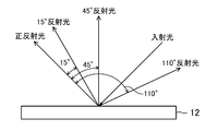
- the FI value was inclined 45 ° from the regular reflection direction to the incident direction side when light was incident on the surface of the laminated coating film 12 at an angle inclined by 45 ° from the normal to the surface.
- Lightness index L * 45 ° of reflected light (45 ° reflected light) lightness index L * 15 ° of reflected light (15 ° reflected light) inclined 15 ° from the regular reflection direction toward the incident direction, and from the regular reflection direction
- the value is obtained by the following equation.
- FI 2.69 ⁇ (L * 15 ° ⁇ L * 110 °) 1.11 / L * 45 ° 0.86
- the results are shown in FIG. It can be seen that the FI value increases when the area occupation ratio of the glitter material 22 is 30% or more and 90% or less.
- FI 28 or more is possible, and the area occupancy is 45% to 65%.
- Line B is a line in which the total amount of the glittering material and the pigment is 50 parts by weight with respect to 100 parts by weight of the resin in the glittering material-containing layer.
- Each paint of the colored underlayer, the glittering material-containing layer, and the transparent clear layer was applied on a steel material by wet-on-wet and then baked (heated at 140 ° C. for 20 minutes).
- Commercially available carbon black was used as the pigment for the colored underlayer.
- fine carbon black is adopted as the pigment
- vapor-deposited aluminum flakes are adopted as the glittering material, and the area occupation ratio is 50.
- the orientation angle was set to 5% or less and 2 degrees or less.
- Example 2 of multilayer coating (red color development)- Table 2 shows the coating composition of this example.
- the difference from the multilayer coating film example 1 is that not the carbon black but the perylene red is adopted as the pigment of the glittering material-containing layer, and other configurations and manufacturing methods are the same as those of the multilayer coating film example.
- the area occupation ratio of the deposited aluminum flakes in the glittering material-containing layer is 50.5%.
- -Laminated coating film example 3 (red color)- Table 3 shows the coating composition of this example.
- the difference from the multilayer coating film example 1 is that perylene red is used instead of carbon black as the pigment of the glittering material-containing layer and the colored underlayer, and the other configuration and manufacturing method are the same as those of the multilayer coating film example 1 It is.
- the area occupation ratio of the deposited aluminum flakes in the glittering material-containing layer is 50.5%.
- the FI value of the laminated coating film example 2 is lower than that of the laminated coating film example 1 (gray color development).
- the red pigment (perylene red) of the glittering material-containing layer of the laminated coating film example 2 is recognized to strongly reflect light in the visible light high wavelength region. That is, it is recognized that the FI value is low because light is irregularly reflected by the red pigment and the red pigment has a weaker absorption of scattered light by the bright material than the black pigment.
- the FI value of the laminated coating film example 3 is lower than that of the laminated coating film example 2.
- the red pigment is used for the colored underlayer, that is, the light absorption by the colored underlayer is weaker than that of the black pigment.
Abstract
Description
上記着色下地層の表面平滑度がBYK-Gardner社製WaveScan DOI(商品名)による測定値Wdで8以下であり、
上記光輝材含有層の厚さが1.5μm以上6μm以下であり、
上記光輝材含有層に存在する全光輝材を該光輝材含有層の表面に投影したときに該表面において当該光輝材が投影された部分が占める面積占有率が30%以上90%以下であることを特徴とする。
図1に示すように本実施形態の自動車の車体(鋼板)11の表面に設けられた積層塗膜12は、着色下地層14、光輝材含有層15及び透明クリヤ層16を順に積層してなる。車体11の表面にはカチオン電着塗装によって電着塗膜(下塗り)13が形成され、電着塗膜13の上に上記積層塗膜12が設けられている。この積層塗膜12において、着色下地層14は中塗りに相当し、光輝材含有層15及び透明クリヤ層16は上塗りに相当する。
図3に示すように、光輝材含有層30に多数の光輝材22が分散している場合、光は複数の光輝材22によって繰り返し反射される。このような多重反射を経て正反射方向から外れて光輝材含有層30から出て行く散乱光が多くなると、FI値は低くなる。すなわち、FI値を高くするには、上記散乱光を減らすことが重要になる。また、多重反射を経て下地層31に達する光は、この下地層31で乱反射(拡散反射)される。この乱反射が強くなると、FI値が低くなる。従って、FI値を高くするには、下地層31による乱反射を抑えることが重要になる。
光輝材含有層における光輝材の面積占有率及び顔料濃度が積層塗膜のFI値に与える影響を調べた。積層塗膜は、鋼製基板に着色下地層と光輝材含有層を積層した構成とした。
結果を図6に示す。光輝材22の面積占有率が30%以上90%以下であるとき、FI値が大きくなることがわかる。特に、その面積占有率を35%以上75%以下とし、顔料濃度を7質量%以上30質量%以下にすると、FI=28以上が可能になり、その面積占有率を45%以上65%以下とし、顔料濃度を18質量%以上23質量%以下にすると、にすると、FI=34以上が可能になることがわかる。
-積層塗膜例1(グレー発色)-
本例の塗膜構成を表1に示す。

本例の塗膜構成を表2に示す。積層塗膜例1との相違点は、光輝材含有層の顔料として、カーボンブラックではなく、ペリレンレッドを採用した点であり、他の構成及び製法は積層塗膜例と同じである。但し、光輝材含有層における蒸着アルミフレークの面積占有率50.5%である。

本例の塗膜構成を表3に示す。積層塗膜例1との相違点は、光輝材含有層及び着色下地層の顔料として、カーボンブラックではなく、ペリレンレッドを採用した点であり、他の構成及び製法は積層塗膜例1と同じである。但し、光輝材含有層における蒸着アルミフレークの面積占有率50.5%である。

積層塗膜例1-3のFI値を測定した。結果を表4に示す。

12 積層塗膜
13 電着塗膜
14 着色下地層
15 光輝材含有層
16 透明クリヤ層
21 顔料(着色材)
22 光輝材
23 顔料(着色材)
Claims (9)
- 被塗物の表面に直接又は間接的に形成された着色材を含有する着色下地層と、該着色下地層の上に重ねられた、フレーク状光輝材及び着色材を含有する光輝材含有層とを備え、
上記着色下地層の表面平滑度がBYK-Gardner社製WaveScan DOI(商品名)による測定値Wdで8以下であり、
上記光輝材含有層の厚さが1.5μm以上6μm以下であり、
上記光輝材含有層に存在する全光輝材を該光輝材含有層の表面に投影したときに該表面において当該光輝材が投影された部分が占める面積占有率が30%以上90%以下であることを特徴とする積層塗膜。 - 請求項1において、
上記光輝材含有層の上記着色材の濃度が7質量%以上30質量%以下であることを特徴とする積層塗膜。 - 請求項1又は請求項2において、
上記光輝材がアルミフレークであり、その厚さが25nm以上200nm以下であることを特徴とする積層塗膜。 - 請求項3において、
上記光輝材含有層の表面に対する上記アルミフレークの配向角が3度以下であることを特徴とする積層塗膜。 - 請求項1乃至請求項4のいずれか一において、
上記着色下地層及び光輝材含有層各々の着色材が濃色系であることを特徴とする積層塗膜。 - 請求項5において、
上記着色下地層の着色材と上記光輝材含有層の着色材が同色系であることを特徴とする積層塗膜。 - 請求項6において、
上記着色下地層及び光輝材含有層各々の着色材が黒色系であることを特徴とする積層塗膜。 - 請求項1乃至請求項7のいずれか一において、
上記光輝材含有層の上に透明クリヤ層が直接積層されていることを特徴とする積層塗膜。 - 請求項1乃至請求項8のいずれか一に記載された積層塗膜を備えていることを特徴とする塗装物。
Priority Applications (7)
| Application Number | Priority Date | Filing Date | Title |
|---|---|---|---|
| DE112016002666.8T DE112016002666T5 (de) | 2015-07-08 | 2016-06-22 | Mehrschichtiger Beschichtungsfilm und beschichtetes Erzeugnis |
| RU2018104317A RU2686209C1 (ru) | 2015-07-08 | 2016-06-22 | Многослойная пленка покрытия и покрытый объект |
| US15/741,829 US20180194111A1 (en) | 2015-07-08 | 2016-06-22 | Multilayer coating film and coated article |
| EP16821009.4A EP3320985B1 (en) | 2015-07-08 | 2016-06-22 | Multilayer coating film and coated article |
| MX2018000114A MX2018000114A (es) | 2015-07-08 | 2016-06-22 | Pelicula de revestimiento de multiples capas y articulo revestido. |
| CN201680035460.5A CN107735185B (zh) | 2015-07-08 | 2016-06-22 | 叠层涂膜及涂装物 |
| CA2991282A CA2991282C (en) | 2015-07-08 | 2016-06-22 | Multilayer coating film and coated article |
Applications Claiming Priority (2)
| Application Number | Priority Date | Filing Date | Title |
|---|---|---|---|
| JP2015137202A JP6330743B2 (ja) | 2015-07-08 | 2015-07-08 | 積層塗膜及び塗装物 |
| JP2015-137202 | 2015-07-08 |
Publications (1)
| Publication Number | Publication Date |
|---|---|
| WO2017006530A1 true WO2017006530A1 (ja) | 2017-01-12 |
Family
ID=57685342
Family Applications (1)
| Application Number | Title | Priority Date | Filing Date |
|---|---|---|---|
| PCT/JP2016/003019 WO2017006530A1 (ja) | 2015-07-08 | 2016-06-22 | 積層塗膜及び塗装物 |
Country Status (9)
| Country | Link |
|---|---|
| US (1) | US20180194111A1 (ja) |
| EP (1) | EP3320985B1 (ja) |
| JP (1) | JP6330743B2 (ja) |
| CN (1) | CN107735185B (ja) |
| CA (1) | CA2991282C (ja) |
| DE (1) | DE112016002666T5 (ja) |
| MX (1) | MX2018000114A (ja) |
| RU (1) | RU2686209C1 (ja) |
| WO (1) | WO2017006530A1 (ja) |
Cited By (3)
| Publication number | Priority date | Publication date | Assignee | Title |
|---|---|---|---|---|
| WO2017094680A1 (ja) * | 2015-12-02 | 2017-06-08 | マツダ株式会社 | 積層塗膜及び塗装物 |
| WO2017146150A1 (ja) * | 2016-02-26 | 2017-08-31 | マツダ株式会社 | 積層塗膜及び塗装物 |
| EP3603822A4 (en) * | 2017-03-29 | 2021-01-20 | Kansai Paint Co., Ltd | METHOD FOR FORMING A MULTI-LAYER COATING FILM |
Families Citing this family (6)
| Publication number | Priority date | Publication date | Assignee | Title |
|---|---|---|---|---|
| US11565281B2 (en) | 2017-09-18 | 2023-01-31 | Kansai Paint Co., Ltd. | Method for forming multilayer coating film |
| US11407210B2 (en) | 2017-12-15 | 2022-08-09 | Kansai Paint Co., Ltd. | Layered body |
| JP6933587B2 (ja) * | 2018-01-18 | 2021-09-08 | 豊田合成株式会社 | ミリ波透過性光沢塗膜及び樹脂製品 |
| CN112654435A (zh) * | 2018-08-31 | 2021-04-13 | 关西涂料株式会社 | 多层涂膜形成方法 |
| JP6945030B1 (ja) * | 2020-03-30 | 2021-10-06 | 大日本塗料株式会社 | 塗料組成物 |
| JP2022078782A (ja) * | 2020-11-13 | 2022-05-25 | マツダ株式会社 | 積層塗膜及び塗装物 |
Citations (10)
| Publication number | Priority date | Publication date | Assignee | Title |
|---|---|---|---|---|
| JP2000017205A (ja) * | 1998-06-30 | 2000-01-18 | Nippon Paint Co Ltd | 塗料組成物、塗膜形成方法及び塗装物 |
| JP2000084473A (ja) * | 1998-09-16 | 2000-03-28 | Nippon Paint Co Ltd | 積層塗膜の形成方法及び補修方法 |
| JP2005144338A (ja) * | 2003-11-17 | 2005-06-09 | Kansai Paint Co Ltd | 塗装方法 |
| JP2005205262A (ja) * | 2004-01-20 | 2005-08-04 | Kansai Paint Co Ltd | 複層塗膜形成方法及び塗装物品 |
| JP2006182966A (ja) * | 2004-12-28 | 2006-07-13 | Nippon Paint Co Ltd | 顔料分散体及び塗料 |
| JP2006181505A (ja) * | 2004-12-28 | 2006-07-13 | Nissan Motor Co Ltd | メタリック塗装方法及び積層塗膜 |
| JP2011025101A (ja) * | 2009-07-21 | 2011-02-10 | Nippon Paint Co Ltd | 光輝性複層塗膜の形成方法 |
| JP2011162732A (ja) * | 2010-02-15 | 2011-08-25 | Kansai Paint Co Ltd | メタリック塗料組成物及び塗膜形成方法 |
| JP2011251253A (ja) * | 2010-06-02 | 2011-12-15 | Nippon Paint Co Ltd | 複層塗膜形成方法 |
| WO2016088294A1 (ja) * | 2014-12-02 | 2016-06-09 | マツダ株式会社 | 積層塗膜及び塗装物 |
Family Cites Families (7)
| Publication number | Priority date | Publication date | Assignee | Title |
|---|---|---|---|---|
| US7851026B2 (en) * | 2003-11-17 | 2010-12-14 | Kansai Paint Co. Ltd. | Method of forming a multi-layer coating including a metallic base coating and a colored clear coating on a substrate |
| WO2007126107A1 (ja) * | 2006-04-25 | 2007-11-08 | Kansai Paint Co., Ltd. | 複層塗膜形成方法 |
| WO2007145368A1 (ja) * | 2006-06-16 | 2007-12-21 | Kansai Paint Co., Ltd. | 塗料組成物 |
| JP5583031B2 (ja) * | 2009-01-15 | 2014-09-03 | 関西ペイント株式会社 | 複層塗膜形成方法 |
| JP5567297B2 (ja) * | 2009-07-14 | 2014-08-06 | 関西ペイント株式会社 | 塗膜形成方法 |
| WO2012002569A1 (en) * | 2010-07-02 | 2012-01-05 | Kansai Paint Co., Ltd. | Method for forming multilayer coating film |
| CN104136135A (zh) * | 2012-03-01 | 2014-11-05 | 本田技研工业株式会社 | 多层涂膜形成方法 |
-
2015
- 2015-07-08 JP JP2015137202A patent/JP6330743B2/ja active Active
-
2016
- 2016-06-22 WO PCT/JP2016/003019 patent/WO2017006530A1/ja active Application Filing
- 2016-06-22 CA CA2991282A patent/CA2991282C/en active Active
- 2016-06-22 EP EP16821009.4A patent/EP3320985B1/en active Active
- 2016-06-22 CN CN201680035460.5A patent/CN107735185B/zh active Active
- 2016-06-22 RU RU2018104317A patent/RU2686209C1/ru active
- 2016-06-22 MX MX2018000114A patent/MX2018000114A/es unknown
- 2016-06-22 US US15/741,829 patent/US20180194111A1/en not_active Abandoned
- 2016-06-22 DE DE112016002666.8T patent/DE112016002666T5/de active Pending
Patent Citations (10)
| Publication number | Priority date | Publication date | Assignee | Title |
|---|---|---|---|---|
| JP2000017205A (ja) * | 1998-06-30 | 2000-01-18 | Nippon Paint Co Ltd | 塗料組成物、塗膜形成方法及び塗装物 |
| JP2000084473A (ja) * | 1998-09-16 | 2000-03-28 | Nippon Paint Co Ltd | 積層塗膜の形成方法及び補修方法 |
| JP2005144338A (ja) * | 2003-11-17 | 2005-06-09 | Kansai Paint Co Ltd | 塗装方法 |
| JP2005205262A (ja) * | 2004-01-20 | 2005-08-04 | Kansai Paint Co Ltd | 複層塗膜形成方法及び塗装物品 |
| JP2006182966A (ja) * | 2004-12-28 | 2006-07-13 | Nippon Paint Co Ltd | 顔料分散体及び塗料 |
| JP2006181505A (ja) * | 2004-12-28 | 2006-07-13 | Nissan Motor Co Ltd | メタリック塗装方法及び積層塗膜 |
| JP2011025101A (ja) * | 2009-07-21 | 2011-02-10 | Nippon Paint Co Ltd | 光輝性複層塗膜の形成方法 |
| JP2011162732A (ja) * | 2010-02-15 | 2011-08-25 | Kansai Paint Co Ltd | メタリック塗料組成物及び塗膜形成方法 |
| JP2011251253A (ja) * | 2010-06-02 | 2011-12-15 | Nippon Paint Co Ltd | 複層塗膜形成方法 |
| WO2016088294A1 (ja) * | 2014-12-02 | 2016-06-09 | マツダ株式会社 | 積層塗膜及び塗装物 |
Non-Patent Citations (1)
| Title |
|---|
| See also references of EP3320985A4 * |
Cited By (6)
| Publication number | Priority date | Publication date | Assignee | Title |
|---|---|---|---|---|
| WO2017094680A1 (ja) * | 2015-12-02 | 2017-06-08 | マツダ株式会社 | 積層塗膜及び塗装物 |
| JPWO2017094680A1 (ja) * | 2015-12-02 | 2018-09-13 | マツダ株式会社 | 積層塗膜及び塗装物 |
| WO2017146150A1 (ja) * | 2016-02-26 | 2017-08-31 | マツダ株式会社 | 積層塗膜及び塗装物 |
| JPWO2017146150A1 (ja) * | 2016-02-26 | 2018-12-20 | マツダ株式会社 | 積層塗膜及び塗装物 |
| EP3603822A4 (en) * | 2017-03-29 | 2021-01-20 | Kansai Paint Co., Ltd | METHOD FOR FORMING A MULTI-LAYER COATING FILM |
| US11389830B2 (en) | 2017-03-29 | 2022-07-19 | Kansai Paint Co., Ltd. | Method for forming multilayer coating film |
Also Published As
| Publication number | Publication date |
|---|---|
| EP3320985B1 (en) | 2024-03-06 |
| CA2991282C (en) | 2020-05-05 |
| DE112016002666T5 (de) | 2018-03-01 |
| RU2686209C1 (ru) | 2019-04-24 |
| CN107735185A (zh) | 2018-02-23 |
| CA2991282A1 (en) | 2017-01-12 |
| JP2017019147A (ja) | 2017-01-26 |
| MX2018000114A (es) | 2018-03-22 |
| JP6330743B2 (ja) | 2018-05-30 |
| EP3320985A1 (en) | 2018-05-16 |
| EP3320985A4 (en) | 2019-03-06 |
| CN107735185B (zh) | 2022-01-28 |
| US20180194111A1 (en) | 2018-07-12 |
Similar Documents
| Publication | Publication Date | Title |
|---|---|---|
| WO2017006530A1 (ja) | 積層塗膜及び塗装物 | |
| JP6330742B2 (ja) | 積層塗膜の設計方法 | |
| US20170218206A1 (en) | Multilayer coating film and coated object | |
| CN109789439B (zh) | 叠层涂膜及涂装物 | |
| WO2018061217A1 (ja) | 積層塗膜及び塗装物 | |
| CN109789438B (zh) | 叠层涂膜及涂装物 | |
| JP6468296B2 (ja) | 積層塗膜及び塗装物 | |
| JP6562148B2 (ja) | 積層塗膜及び塗装物 | |
| JP6156427B2 (ja) | 積層塗膜及び塗装物 |
Legal Events
| Date | Code | Title | Description |
|---|---|---|---|
| 121 | Ep: the epo has been informed by wipo that ep was designated in this application |
Ref document number: 16821009 Country of ref document: EP Kind code of ref document: A1 |
|
| ENP | Entry into the national phase |
Ref document number: 2991282 Country of ref document: CA |
|
| WWE | Wipo information: entry into national phase |
Ref document number: 112016002666 Country of ref document: DE Ref document number: MX/A/2018/000114 Country of ref document: MX |
|
| WWE | Wipo information: entry into national phase |
Ref document number: 2016821009 Country of ref document: EP Ref document number: 2018104317 Country of ref document: RU |