WO2017006435A1 - 原子間力顕微鏡およびその制御方法 - Google Patents
原子間力顕微鏡およびその制御方法 Download PDFInfo
- Publication number
- WO2017006435A1 WO2017006435A1 PCT/JP2015/069552 JP2015069552W WO2017006435A1 WO 2017006435 A1 WO2017006435 A1 WO 2017006435A1 JP 2015069552 W JP2015069552 W JP 2015069552W WO 2017006435 A1 WO2017006435 A1 WO 2017006435A1
- Authority
- WO
- WIPO (PCT)
- Prior art keywords
- sample
- scanning
- interaction
- cantilever
- information
- Prior art date
- Legal status (The legal status is an assumption and is not a legal conclusion. Google has not performed a legal analysis and makes no representation as to the accuracy of the status listed.)
- Ceased
Links
Images





Classifications
-
- G—PHYSICS
- G01—MEASURING; TESTING
- G01Q—SCANNING-PROBE TECHNIQUES OR APPARATUS; APPLICATIONS OF SCANNING-PROBE TECHNIQUES, e.g. SCANNING PROBE MICROSCOPY [SPM]
- G01Q10/00—Scanning or positioning arrangements, i.e. arrangements for actively controlling the movement or position of the probe
- G01Q10/04—Fine scanning or positioning
- G01Q10/06—Circuits or algorithms therefor
- G01Q10/065—Feedback mechanisms, i.e. wherein the signal for driving the probe is modified by a signal coming from the probe itself
-
- G—PHYSICS
- G01—MEASURING; TESTING
- G01Q—SCANNING-PROBE TECHNIQUES OR APPARATUS; APPLICATIONS OF SCANNING-PROBE TECHNIQUES, e.g. SCANNING PROBE MICROSCOPY [SPM]
- G01Q60/00—Particular types of SPM [Scanning Probe Microscopy] or microscopes; Essential components thereof
- G01Q60/24—AFM [Atomic Force Microscopy] or apparatus therefor, e.g. AFM probes
-
- G—PHYSICS
- G01—MEASURING; TESTING
- G01Q—SCANNING-PROBE TECHNIQUES OR APPARATUS; APPLICATIONS OF SCANNING-PROBE TECHNIQUES, e.g. SCANNING PROBE MICROSCOPY [SPM]
- G01Q60/00—Particular types of SPM [Scanning Probe Microscopy] or microscopes; Essential components thereof
- G01Q60/24—AFM [Atomic Force Microscopy] or apparatus therefor, e.g. AFM probes
- G01Q60/32—AC mode
Definitions
- the present invention relates to a scanning probe microscope, and more particularly to an atomic force microscope used for observation of a biological sample.
- a scanning probe microscope is a scanning microscope that mechanically scans a mechanical probe to obtain information on the surface of a sample, and includes a scanning tunneling microscope (STM), an atomic force microscope (AFM), a scanning Generic name of scanning magnetic force microscope (MFM), scanning capacitance microscope (SCaM), scanning near-field light microscope (SNOM), etc.
- STM scanning tunneling microscope
- AFM atomic force microscope
- MFM scanning Generic name of scanning magnetic force microscope
- SCaM scanning capacitance microscope
- SNOM scanning near-field light microscope
- the atomic force microscope (hereinafter referred to as AFM) is the most widely used device, which has a mechanical probe at its free end, an optical displacement sensor that detects the displacement of the cantilever, a cantilever, A scanner that scans relative to the sample is provided. A mechanical interaction is generated between the mechanical probe and the sample, and information on the sample is obtained based on the deformation of the cantilever caused by the mechanical interaction.
- AFM for soft matter observation that observes soft samples such as biological samples and gels in liquids has attracted attention.
- AFM how the influence on the sample can be reduced, more specifically, how the deformation of the sample caused by the mechanical interaction between the mechanical probe and the sample can be reduced. ,is important.
- the interaction is reduced by devising a closed loop control that keeps the distance between the cantilever and the sample constant.
- the deformation of the sample is almost linear with the size of the interaction, and it is certainly effective to reduce the interaction, but the time during which the interaction works is also an important parameter. This is because in the case of a soft sample such as a gel, even if the interaction is reduced, the deformation of the sample tends to increase as the interaction time increases. This can be a big problem in AFM for soft matter observation that observes a soft sample such as a gel.
- An object of the present invention is to provide an atomic force microscope in which deformation of a sample is reduced and a control method thereof by reducing the influence of the time during which an interaction works in a soft sample such as a gel.
- the present invention acquires sample information by performing relative raster scanning between the cantilever and the sample along the XY plane while causing an interaction between the probe provided at the free end of the cantilever and the sample.
- This atomic force microscope has a raster scanning information generating unit that generates raster scanning information, a raster scanning control unit that controls raster scanning based on the raster scanning information, and a magnitude of interaction based on the raster scanning information.
- an interaction control unit for controlling.
- the interaction control unit relatively reduces the magnitude of the interaction when the relative velocity between the cantilever and the sample along the XY plane of the raster scan relatively decreases.
- the interaction control unit relatively reduces the magnitude of the interaction when the interaction time increases, thereby reducing the deformation of the sample.
- FIG. 1 shows an atomic force microscope according to the first embodiment.
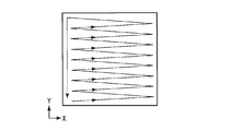
- FIG. 2 shows a raster scan trajectory of the probe relative to the sample.
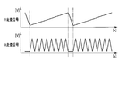
- FIG. 3 shows waveforms of the X scanning signal and the Y scanning signal for causing the X scanner and the Y scanner to perform the raster scanning shown in FIG.
- FIG. 4 is an enlarged view of a part of the X scanning signal shown in FIG.
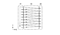
- FIG. 5 shows a scanning region in which the relative speed between the probe and the sample is reduced in addition to the raster scanning locus.
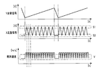
- FIG. 6 shows signal areas respectively corresponding to scanning areas in which the relative velocity between the probe and the sample decreases, in addition to the waveform of the scanning signal for raster scanning.
- FIG. 1 shows an atomic force microscope according to the first embodiment.
- FIG. 2 shows a raster scan trajectory of the probe relative to the sample.
- FIG. 3 shows waveforms of the X scanning signal and the Y scanning signal for causing the X scanner and the Y scanner to
- FIG. 7 shows changes in the relative velocity of the probe and the sample by raster scanning in addition to the waveform of the scanning signal shown in FIG.
- FIG. 8 shows an atomic force microscope according to the second embodiment.
- FIG. 9 shows the waveform of the timing signal reflecting the change in relative speed in addition to the change in the X scan signal waveform and the relative speed shown in FIG.
- FIG. 10 shows a scanning region in which the relative velocity between the cantilever and the sample is reduced, and a region in which these scanning regions are excluded from the entire scanning region.
- the first embodiment solves this problem, and the first embodiment will be described below with reference to FIG.
- FIG. 1 shows an atomic force microscope 100 of the present embodiment.
- the atomic force microscope 100 has a cantilever 102 having a probe 101 at a free end.
- This cantilever 102 is held by a holder 104 and is arranged so that the probe 101 faces the sample 103.
- the sample 103 is held on the Z scanner 107 via a sample table (not shown).
- An optical lever sensor 106 for optically detecting the displacement of the cantilever 102 is disposed on the cantilever 102.
- the optical lever sensor 106 includes a laser light source 106a that irradiates the back surface of the cantilever 102 with a laser light 106b, a multi-segment detector 106d that receives the laser light 106c reflected from the back surface of the cantilever 102, and an output signal of the multi-segment detector 106d. Based on this, it is composed of an operational amplifier 106e that calculates and outputs a displacement signal of the cantilever 102.
- the displacement signal of the cantilever 102 output from the operational amplifier 106e includes an AC signal reflecting the vibration of the cantilever 102 described later.
- a displacement signal of the cantilever 102 is supplied to the Z control unit 113.
- a piezoelectric element 105 is provided on the holder 104.
- the piezoelectric element 105 operates as a vibrator that vibrates the cantilever 102 via the holder 104.
- the piezoelectric element 105 is controlled by the vibration signal generator 112 and vibrates the cantilever 102 based on the vibration signal output from the vibration signal generator 112. That is, the vibration of the cantilever 102 is controlled by the vibration signal generator 112.
- the Z scanner 107 scans the sample 103 along the Z direction with respect to the cantilever 102.
- the Z scanner 107 is mounted on the X scanner 108a mounted on the Y scanner 108b.
- the Z scanner 107 is controlled by the Z control unit 113.
- the Z control unit 113 receives a displacement signal including an AC signal reflecting the vibration of the cantilever 102, generates a Z scanning signal for keeping the amplitude value of the displacement signal constant, and based on the Z scanning signal 107 is expanded and contracted along the Z direction, and the sample 103 is scanned along the Z direction with respect to the cantilever 102. That is, the relative distance along the Z direction between the cantilever 102 and the sample 103 is controlled by the Z control unit 113.
- the Z scanning signal generated by the Z control unit 113 is also supplied to the sample information acquisition unit 115.
- the raster scanning control unit 108 includes an X scanner 108a, a Y scanner 108b, and an XY scanning control unit 108c.
- the X scanner 108a and the Y scanner 108b cause the sample 103 to perform raster scanning along the XY plane with respect to the cantilever 102.
- the X scanner 108a and the Y scanner 108b are controlled by the XY scanning control unit 108c.
- the X scanner 108 a and the Y scanner 108 b are displaced along the X direction and the Y direction, respectively, based on the X scanning signal and the Y scanning signal output from the XY scanning control unit 108 c, thereby causing the sample 103 to move to the cantilever 102.
- raster scanning is performed along the XY plane.
- the controller 110 includes an interaction control unit 111, an XY scanning control unit 108c, a raster scanning information generation unit 114, and a sample information acquisition unit 115.
- the raster scanning information generation unit 114 generates raster scanning information necessary for desired raster scanning.
- the raster scanning information is supplied to the XY scanning control unit 108c, the interaction control unit 111, and the sample information acquisition unit 115.
- the raster scan information includes information on stopping the raster scan when the raster scan is stopped.
- the XY scan control unit 108c generates an X scan signal and a Y scan signal based on the raster scan information. Accordingly, the raster scan is controlled by the raster scan control unit 108 including the X scanner 108a, the Y scanner 108b, and the XY scan control unit 108c based on the raster scan information.
- the interaction control unit 111 includes an excitation signal generator 112 and a Z control unit 113. Therefore, the piezoelectric element 105 can be controlled by the interaction control unit 111 including the excitation signal generator 112. That is, the interaction control unit 111 can control the vibration of the cantilever 102. Further, the Z scanner 107 can be controlled by the interaction control unit 111 including the Z control unit 113. That is, the interaction control unit 111 can control the relative distance between the cantilever 102 and the sample 103 in the Z direction. The interaction control unit 111 changes, for example, the amplitude of vibration of the cantilever 102 or changes the relative distance along the Z direction between the cantilever 102 and the sample 103 based on the raster scanning information.
- the magnitude of the mechanical interaction between the probe 101 and the sample 103 becomes relative. Changes. Specifically, when the vibration amplitude of the cantilever 102 increases, the magnitude of the dynamic interaction between the probe 101 and the sample 103 relatively increases, and when the vibration amplitude of the cantilever 102 decreases, the probe 101 and the sample The magnitude of the dynamic interaction between 103 is relatively reduced.
- the interaction control unit 111 can control the magnitude of the dynamic interaction between the probe 101 and the sample 103 based on the raster scanning information.
- the sample information acquisition unit 115 acquires sample information such as surface shape information based on the supplied Z scanning signal and raster scanning information, and generates image data for mapping the acquired sample information.
- the sample information display unit 116 displays the image data generated by the sample information acquisition unit 115.
- An input device 117 is connected to the controller 110.
- the input device 117 is for, for example, installing a control method program disclosed herein in the controller 110, designating an observation region, and issuing commands such as observation start and observation end to the controller 110. is there.
- the vibration signal generator 112 outputs a vibration signal and supplies the vibration signal to the piezoelectric element 105 that operates as the vibration generator.
- the piezoelectric element 105 vibrates the cantilever 102 near its mechanical resonance frequency based on the excitation signal.
- the optical lever sensor 106 disposed on the top of the cantilever 102 detects the displacement of the cantilever 102 and supplies a displacement signal including an AC signal reflecting the vibration of the cantilever 102 to the Z control unit 113.
- the raster scanning information generation unit 114 generates raster scanning information necessary for desired raster scanning.
- the raster scanning information is supplied to the XY scanning control unit 108c, the interaction control unit 111, and the sample information acquisition unit 115. This raster scan information does not include information regarding the stop of raster scan.
- the XY scan control unit 108c outputs an X scan signal and a Y scan signal based on the raster scan information.
- the X scanner 108a and the Y scanner 108b receive the X scanning signal and the Y scanning signal, respectively, and cause the sample 103 to perform raster scanning along the XY plane with respect to the cantilever 102. At this time, the relative velocity between the probe 101 and the sample 103 along the XY plane is greater than zero.
- the Z control unit 113 in the interaction control unit 111 receives a displacement signal including an AC signal reflecting the vibration of the cantilever 102, and a Z scanning signal for keeping the amplitude value of the displacement signal constant, for example.
- a displacement signal including an AC signal reflecting the vibration of the cantilever 102
- a Z scanning signal for keeping the amplitude value of the displacement signal constant, for example.
- the Z scanner 107 is expanded and contracted along the Z direction, and the sample 103 is scanned along the Z direction with respect to the cantilever 102.
- the Z scanning signal is also supplied to the sample information acquisition unit 115.
- the sample information acquisition unit 115 acquires sample information such as surface shape information based on the supplied Z scanning signal and raster scanning information, and generates image data for mapping the acquired sample information.
- the sample information display unit 116 displays the image data generated by the sample information acquisition unit 115.
- the raster scan information generation unit 114 When the acquisition of the sample information is finished, the raster scan information generation unit 114 generates raster scan information including scan stop information related to the stop of the raster scan. This raster scanning information is supplied to the XY scanning control unit 108c, the interaction control unit 111, and the sample information acquisition unit 115.
- the XY scan control unit 108c stops the output of the X scan signal and the Y scan signal based on the scan stop information in the raster scan information.
- the X scanner 108a and the Y scanner 108b stop raster scanning. That is, the raster scan is stopped by the raster scan control unit 108 including the X scanner 108a, the Y scanner 108b, and the XY scan control unit 108c based on the scan stop information in the raster scan information.
- the interaction control unit 111 receives the scan stop information in the raster scan information, and, for example, reduces the amplitude of vibration of the cantilever 102 simultaneously with the stop of the raster scan, or along the Z direction of the cantilever 102 and the sample 103. Increase the relative distance. In other words, the interaction control unit 111 reduces the amplitude of vibration of the cantilever 102 based on the scanning stop information in the raster scanning information, or the relative distance along the Z direction between the cantilever 102 and the sample 103. Is increased, the magnitude of the mechanical interaction between the probe 101 and the sample 103 is relatively reduced.
- the sample information acquisition unit 115 receives the scan stop information in the raster scan information and stops the sample information acquisition.
- the amplitude of vibration of the cantilever 102 is reduced, or the relative distance along the Z direction between the cantilever 102 and the sample 103 is increased.
- the magnitude of the interaction between the probe 101 and the sample 103 is relatively reduced.
- the problem that the probe pierces deeply into a soft sample such as a gel by stopping the raster scanning is avoided.
- the time during which the interaction works is considered as the time for the probe to pass the unit length along the XY plane of the sample surface.
- the time for the probe to pass through the unit length along the XY plane of the sample surface is equal to the reciprocal of the relative velocity between the probe and the sample along the XY plane. That is, the time during which the interaction works is inversely proportional to the relative velocity between the probe and the sample along the XY plane. Therefore, the tendency for the deformation of the sample to increase as the interaction time becomes longer can be restated as the tendency for the deformation of the sample to increase as the relative speed between the probe and the sample decreases.
- the state in which the raster scanning is stopped may be rephrased as a state in which the relative speed is zero.
- the relative speed between the probe and the sample is equivalent to the relative speed between the cantilever and the sample.
- FIG. 2 shows a relative raster scanning locus of the probe 101 with respect to the sample 103.
- the trajectory of this raster scan is a conventional one.
- the main scanning line direction of raster scanning (the direction in which the scanning speed is high) is the X direction.
- FIG. 3 shows a waveform of a scanning signal for causing the X scanner 108a and the Y scanner 108b to perform the raster scanning shown in FIG.
- the X scanning signal and the Y scanning signal in FIG. 3 may be considered to be the same as the X scanning signal and the Y scanning signal in the first embodiment, for example.
- the X scanning signal in FIG. 3 has a rounded portion where the signal changes from increasing to decreasing. This is to reduce the harmonic component of the X scanning signal, and has the effect of reducing vibration noise caused by the scanning of the X scanner 108a and the Y scanner 108b operated by the X scanning signal and the Y scanning signal.
- FIG. 5 shows an area in the vicinity of the turning point including the turning point in the X direction of the raster scanning shown in FIG. 2 (the point where the scanning direction is reversed), that is, the search along the XY plane, in addition to the locus of the raster scanning.
- Scanning areas A1 and A2 in which the relative speed between the needle 101 and the sample 103 is reduced are shown.
- FIG. 6 shows signal regions S1 and S2 corresponding to the scanning regions A1 and A2, respectively, in addition to the waveform of the scanning signal for raster scanning.
- FIG. 7 shows a change in the relative speed between the probe 101 and the sample 103 by raster scanning in addition to the waveform of the scanning signal shown in FIG.
- the signal areas S1 and S2 correspond to the area V in the relative speed graph.
- the problem caused by raster scanning is that the relative speed always decreases in the region near the turning point including the turning point in the X direction of raster scanning (the point at which the scanning direction is reversed). As a result, the deformation of the sample increases.
- the vertical cross-sectional shape of the observed image of the sample flips the frying pan. It will be like that. In other words, the vertical cross-sectional shape of the observation image of the sample faithfully reflects the height of the sample except for both ends, but the distortion is large at both ends, and the height is smaller than the actual as it approaches the end. It has become.
- the second embodiment solves this problem, and the second embodiment will be described below with reference to FIGS.
- FIG. 8 shows the atomic force microscope 200 of the present embodiment.
- members denoted by the same reference numerals as those shown in FIG. 1 are the same members, and the description thereof is omitted here.
- the atomic force microscope 200 of the present embodiment has a controller 210, an interaction control unit 211 included therein, and raster scan information generation.
- the part 214 is different.
- the raster scanning information generation unit 214 generates raster scanning information necessary for desired raster scanning.
- the raster scanning information is supplied to the XY scanning control unit 108c, the interaction control unit 211, and the sample information acquisition unit 115.
- the raster scan information indicates a region where the relative speeds of the cantilever 102 and the sample 103 along the X direction are relatively lowered, and includes timing information synchronized with the raster scan in the X direction.
- FIG. 9 shows the waveform of the timing signal in addition to the waveform of the X scanning signal and the change in relative speed shown in FIG.
- the timing signal shown in FIG. 9 indicates that when the relative speed between the probe 101 and the sample 103 along the XY plane decreases, for example, when the relative speed enters the region V, in other words, the relative speed is a predetermined value.
- the relative speed between the probe 101 and the sample 103 along the XY plane is restored, for example, when the relative speed is out of the region V, in other words, the relative speed is a predetermined threshold. It has a pulse that falls when the value is exceeded.
- the width of the pulse indicates a region where the relative speed decreases, and in the entire region of raster scanning, the region including the left and right turning points is less than 10% (scanning regions A1 and A2 in FIG. 5 are each less than 10%). It is.
- the interaction control unit 211 includes an excitation signal generator 212 and a Z control unit 213. Therefore, the piezoelectric element 105 is controlled by the interaction control unit 211 including the excitation signal generator 212. That is, the interaction control unit 211 can control the vibration of the cantilever 102.
- the Z scanner 107 is controlled by an interaction control unit 211 including a Z control unit 213. That is, the interaction control unit 211 can control the relative distance between the cantilever 102 and the sample 103 along the Z direction.
- the interaction control unit 211 changes, for example, the amplitude of vibration of the cantilever 102 based on the timing information included in the raster scanning information, for example, the timing signal shown in FIG. Vary the relative distance along the direction.
- the magnitude of the mechanical interaction between the probe 101 and the sample 103 becomes relative. Changes. Specifically, when the vibration amplitude of the cantilever 102 increases, the magnitude of the dynamic interaction between the probe 101 and the sample 103 relatively increases, and when the vibration amplitude of the cantilever 102 decreases, the probe 101 and the sample The magnitude of the dynamic interaction between 103 is relatively reduced.
- the interaction control unit 211 is configured so that the relative speed has a predetermined threshold value while the pulse of the timing signal shown in FIG. 9 is output. While the distance is lower, for example, by reducing the amplitude of vibration of the cantilever 102 or by increasing the relative distance along the Z direction between the cantilever 102 and the sample 103, the probe 101 and the sample 103 are moved. Relatively reduce the magnitude of mechanical interaction.
- the interaction control unit 211 can control the magnitude of the dynamic interaction between the probe 101 and the sample 103 based on the timing information included in the raster scanning information. Specifically, the interaction control unit 211 performs dynamics between the probe 101 and the sample 103 while the timing information included in the raster scan information, for example, the pulse of the timing signal shown in FIG. The relative interaction magnitude is relatively reduced. In other words, the interaction control unit 211 operates in the X direction while the probe 101 is positioned in the relative speed reduction region where the relative speed in the main scanning direction of the cantilever 102 and the sample 103, that is, the X direction scanning is relatively reduced. The magnitude of the interaction is relatively reduced in synchronization with the scan.
- the timing information included in the raster scan information by the interaction control unit 211 when the relative velocity between the cantilever 102 and the sample 103 along the XY plane relatively decreases, the timing information included in the raster scan information by the interaction control unit 211. , The magnitude of the mechanical interaction between the probe 101 and the sample 103 is relatively reduced.
- the sample information display 116 is removed from the “scanning regions A1, A2 in which the relative velocity between the cantilever and the sample along the XY plane decreases” shown in FIG. Only the sample information of the selected region, that is, the region A3 shown in FIG. 10 may be displayed. That is, the sample information acquisition unit 115 generates image data of the sample information in the region A3 in which the scanning regions A1 and A2 in which the relative velocity between the cantilever and the sample is reduced are excluded from the entire scanning region, and this is generated on the sample information display 116. May be displayed.
Landscapes
- Physics & Mathematics (AREA)
- Health & Medical Sciences (AREA)
- General Health & Medical Sciences (AREA)
- General Physics & Mathematics (AREA)
- Nuclear Medicine, Radiotherapy & Molecular Imaging (AREA)
- Radiology & Medical Imaging (AREA)
- Length Measuring Devices With Unspecified Measuring Means (AREA)
Abstract
原子間力顕微鏡(100)は、カンチレバー(102)の自由端に設けられた探針(101)と試料(103)の間に相互作用を生じさせながら、XY平面に沿ったカンチレバーと試料の間の相対的なラスター走査をおこなって試料情報を取得する。原子間力顕微鏡は、ラスター走査情報を生成するラスター走査情報生成部(114)と、ラスター走査情報に基づいて、ラスター走査を制御するラスター走査制御部(108)と、ラスター走査情報に基づいて、相互作用の大きさを制御する相互作用制御部(111)とを備えている。相互作用制御部は、ラスター走査のXY平面に沿ったカンチレバーと前記試料の相対速度が相対的に減少するとき、相互作用の大きさを相対的に減少させる。
Description
本発明は、走査型プローブ顕微鏡、特に生物試料の観察に用いられる原子間力顕微鏡に関する。
走査型プローブ顕微鏡(SPM)は、機械的探針を機械的に走査して試料表面の情報を得る走査型顕微鏡であって、走査型トンネリング顕微鏡(STM)、原子間力顕微鏡(AFM)、走査型磁気力顕微鏡(MFM)、走査型電気容量顕微鏡(SCaM)、走査型近接場光顕微鏡(SNOM)などの総称である。
走査型プローブ顕微鏡は、機械的探針と試料とを相対的にXY方向にラスター走査しながら、試料の所望とする表面情報を機械的探針を介して得て、ディスプレイ上にマッピング表示する。なかでも原子間力顕微鏡(以下、AFMと呼ぶ)は、最も広く使用されている装置であり、機械的探針をその自由端に持つカンチレバー、カンチレバーの変位を検出する光学式変位センサ、カンチレバーと試料とを相対的に走査するスキャナを備えている。機械的探針と試料の間に力学的な相互作用を生じさせ、その力学的な相互作用によって生じるカンチレバーの変形に基づいて試料の情報を得る。
走査型プローブ顕微鏡は、機械的探針と試料とを相対的にXY方向にラスター走査しながら、試料の所望とする表面情報を機械的探針を介して得て、ディスプレイ上にマッピング表示する。なかでも原子間力顕微鏡(以下、AFMと呼ぶ)は、最も広く使用されている装置であり、機械的探針をその自由端に持つカンチレバー、カンチレバーの変位を検出する光学式変位センサ、カンチレバーと試料とを相対的に走査するスキャナを備えている。機械的探針と試料の間に力学的な相互作用を生じさせ、その力学的な相互作用によって生じるカンチレバーの変形に基づいて試料の情報を得る。
近年、液体中において生体試料やゲルなどの柔らかい試料を観察するソフトマター観察用AFMが注目を集めている。このソフトマター観察用AFMにおいては、試料への影響を如何に小さくできるか、詳しくは、機械的探針と試料の間に働く力学的な相互作用に起因する試料の変形を如何に小さくできるか、が重要である。従来のソフトマター観察用AFMにおいては、例えば日本国特許第4083517号に示されるように、カンチレバーと試料の距離を一定に保つ閉ループ制御を工夫することによって相互作用の低減を図っている。
試料の変形は相互作用の大きさにほぼ線形であり、相互作用を小さくすることは確かに有効であるが、相互作用が働く時間も重要なパラメータである。ゲルなどの柔らかい試料の場合は、相互作用を小さくしたとしても、相互作用が働く時間が長くなるほど試料の変形が大きくなる傾向があるからである。これは、ゲルなどの柔らかい試料を観察するソフトマター観察用AFMにおいては大きな問題となりうる。
しかしながら、従来のソフトマター観察用AFMにおいては、相互作用が働く時間を考慮した装置や方法の例の報告はまだない。
本発明の目的は、ゲルなどの柔らかい試料において、相互作用が働く時間の影響を低減させることにより、試料の変形の低減が図られた原子間力顕微鏡およびその制御方法を提供することである。
本発明は、カンチレバーの自由端に設けられた探針と試料の間に相互作用を生じさせながら、XY平面に沿ったカンチレバーと試料の間の相対的なラスター走査をおこなって試料情報を取得する原子間力顕微鏡に向けられている。この原子間力顕微鏡は、ラスター走査情報を生成するラスター走査情報生成部と、ラスター走査情報に基づいて、ラスター走査を制御するラスター走査制御部と、ラスター走査情報に基づいて、相互作用の大きさを制御する相互作用制御部とを備えている。相互作用制御部は、ラスター走査のXY平面に沿ったカンチレバーと試料の相対速度が相対的に減少するとき、相互作用の大きさを相対的に減少させる。
この原子間力顕微鏡によれば、相互作用制御部によって、相互作用が働く時間が増加するときに相互作用の大きさが相対的に減少されることによって、試料の変形が低減される。
<第一の実施形態>
ゲルなどの柔らかい試料においては、探針と試料の間の相互作用が働く時間が長くなるほど、試料の変形は大きくなる傾向がある。このため、相互作用を生じさせたままラスター走査を停止すると、探針がゲルなどの柔らかい試料に深くまで刺さるという問題が生じる。これはゲルなどの柔らかい試料を観察するソフトマター観察用AFMにおいては、非常に大きな問題である。
ゲルなどの柔らかい試料においては、探針と試料の間の相互作用が働く時間が長くなるほど、試料の変形は大きくなる傾向がある。このため、相互作用を生じさせたままラスター走査を停止すると、探針がゲルなどの柔らかい試料に深くまで刺さるという問題が生じる。これはゲルなどの柔らかい試料を観察するソフトマター観察用AFMにおいては、非常に大きな問題である。
第一の実施形態は、この問題を解決するものであり、この第一の実施形態について、図1を用いて以下に説明する。
図1は、本実施形態の原子間力顕微鏡100を示している。原子間力顕微鏡100は、自由端に探針101を有するカンチレバー102を有している。このカンチレバー102は、ホルダ104に保持されており、探針101が試料103と正対するように配置されている。試料103は、図示しない試料台を介してZスキャナ107上に保持されている。
カンチレバー102の上部には、カンチレバー102の変位を光学的に検出するための光てこセンサ106が配置されている。この光てこセンサ106は、カンチレバー102の背面にレーザ光106bを照射するレーザ光源106aと、カンチレバー102の背面から反射されたレーザ光106cを受けるマルチセグメントディテクタ106dと、マルチセグメントディテクタ106dの出力信号に基づいてカンチレバー102の変位信号を算出して出力する演算アンプ106eから構成されている。演算アンプ106eから出力されるカンチレバー102の変位信号には、後述するカンチレバー102の振動を反映した交流信号が含まれる。カンチレバー102の変位信号は、Z制御部113に供給される。
ホルダ104上には圧電素子105が設けられている。圧電素子105は、ホルダ104を介してカンチレバー102を振動させる加振器として動作する。この圧電素子105は、加振信号発生器112により制御され、加振信号発生器112から出力される加振信号に基づいてカンチレバー102を振動させる。すなわち加振信号発生器112によってカンチレバー102の振動が制御される。
Zスキャナ107は、試料103を、カンチレバー102に対してZ方向に沿って走査させるものである。Zスキャナ107は、Yスキャナ108bに搭載されたXスキャナ108aに搭載されている。Zスキャナ107は、Z制御部113により制御される。詳しくは、Z制御部113は、カンチレバー102の振動を反映した交流信号を含む変位信号を受け、その変位信号の例えば振幅値を一定に保つためのZ走査信号を生成し、それに基づいてZスキャナ107をZ方向に沿って伸縮させ、試料103を、カンチレバー102に対してZ方向に沿って走査させる。すなわちZ制御部113によってカンチレバー102と試料103のZ方向に沿った相対距離が制御される。Z制御部113によって生成されたZ走査信号は、試料情報取得部115にも供給される。
ラスター走査制御部108は、Xスキャナ108aとYスキャナ108bとXY走査制御部108cを備えている。
Xスキャナ108aとYスキャナ108bは、試料103を、カンチレバー102に対してXY平面に沿ってラスター走査させるものである。Xスキャナ108aとYスキャナ108bは、XY走査制御部108cにより制御される。Xスキャナ108aとYスキャナ108bは、XY走査制御部108cから出力されるX走査信号とY走査信号に基づいて、それぞれX方向とY方向に沿って変位し、それによって試料103を、カンチレバー102に対してXY平面に沿ってラスター走査させる。
コントローラ110は、相互作用制御部111とXY走査制御部108cとラスター走査情報生成部114と試料情報取得部115を有している。
ラスター走査情報生成部114は、所望のラスター走査に必要なラスター走査情報を生成する。ラスター走査情報は、XY走査制御部108cと相互作用制御部111と試料情報取得部115に供給される。このラスター走査情報には、ラスター走査を停止させる際には、ラスター走査の停止に関する情報が含まれる。
XY走査制御部108cでは、ラスター走査情報に基づいてX走査信号とY走査信号を生成する。従ってラスター走査は、ラスター走査情報に基づいて、Xスキャナ108aとYスキャナ108bとXY走査制御部108cを備えたラスター走査制御部108によって制御される。
相互作用制御部111は、加振信号発生器112とZ制御部113を備えている。従って圧電素子105は、加振信号発生器112を備えた相互作用制御部111によって制御可能になる。すなわち相互作用制御部111は、カンチレバー102の振動を制御し得る。またZスキャナ107は、Z制御部113を備えた相互作用制御部111によって制御可能になる。すなわち相互作用制御部111は、カンチレバー102と試料103のZ方向に沿った相対距離を制御し得る。相互作用制御部111は、ラスター走査情報に基づいて、例えば、カンチレバー102の振動の振幅を変化させる、あるいは、カンチレバー102と試料103のZ方向に沿った相対距離を変化させる。
例えば、カンチレバー102の振動の振幅が変化すると、あるいは、カンチレバー102と試料103のZ方向に沿った相対距離が変化すると、探針101と試料103の間の力学的な相互作用の大きさが相対的に変化する。詳しくは、カンチレバー102の振動の振幅が大きくなると探針101と試料103の間の力学的な相互作用の大きさは相対的に増加し、カンチレバー102の振動の振幅が小さくなると探針101と試料103の間の力学的な相互作用の大きさは相対的に減少する。また、カンチレバー102と試料103のZ方向に沿った相対距離が大きくなると探針101と試料103の間の力学的な相互作用の大きさは相対的に減少し、カンチレバー102と試料103のZ方向に沿った相対距離が小さくなると探針101と試料103の間の力学的な相互作用の大きさは相対的に増加する。
このように、相互作用制御部111は、ラスター走査情報に基づいて、探針101と試料103の間の力学的な相互作用の大きさを制御し得る。
試料情報取得部115は、供給されるZ走査信号とラスター走査情報に基づいて、試料情報たとえば表面形状情報を取得し、取得した試料情報をマッピングするための画像データを生成する。
試料情報表示器116は、試料情報取得部115で生成された画像データを表示する。
コントローラ110には、入力機器117が接続されている。入力機器117は、例えば、ここにおいて開示された制御方法のプログラムをコントローラ110にインストールしたり、観察領域を指定したり、観察開始や観察終了などの指令をコントローラ110に出したりするためのものである。
次に、このように構成された第一の実施形態の原子間力顕微鏡の動作の流れを説明する。
加振信号発生器112が加振信号を出力し、加振信号を加振器として動作する圧電素子105に供給する。
圧電素子105は、加振信号に基づいてカンチレバー102をその機械的共振周波数近傍で振動させる。
カンチレバー102の上部に配置された光てこセンサ106は、カンチレバー102の変位を検出し、カンチレバー102の振動を反映した交流信号が含まれる変位信号をZ制御部113に供給する。
ラスター走査情報生成部114は、所望のラスター走査に必要なラスター走査情報を生成する。ラスター走査情報は、XY走査制御部108cと相互作用制御部111と試料情報取得部115に供給される。このラスター走査情報には、ラスター走査の停止に関する情報は含まれない。
XY走査制御部108cは、ラスター走査情報に基づいてX走査信号とY走査信号を出力する。
Xスキャナ108aとYスキャナ108bは、それぞれX走査信号とY走査信号を受けて、試料103を、カンチレバー102に対してXY平面に沿ってラスター走査させる。このときXY平面に沿った探針101と試料103の相対速度はゼロよりも大きくなる。
ラスター走査と同時に、相互作用制御部111内のZ制御部113は、カンチレバー102の振動を反映した交流信号を含む変位信号を受け、その変位信号の例えば振幅値を一定に保つためのZ走査信号を生成し、それに基づいてZスキャナ107をZ方向に沿って伸縮させ、試料103を、カンチレバー102に対してZ方向に沿って走査させる。Z走査信号は、試料情報取得部115にも供給される。
試料情報取得部115は、供給されるZ走査信号とラスター走査情報に基づいて、試料情報たとえば表面形状情報を取得し、取得した試料情報をマッピングするための画像データを生成する。
試料情報表示器116は、試料情報取得部115で生成された画像データを表示する。
試料情報の取得を終了する場合、ラスター走査情報生成部114は、ラスター走査の停止に関する走査停止情報を含んだラスター走査情報を生成する。このラスター走査情報は、XY走査制御部108cと相互作用制御部111と試料情報取得部115に供給される。
XY走査制御部108cは、ラスター走査情報中の走査停止情報に基づいてX走査信号とY走査信号の出力を停止する。これを受けて、Xスキャナ108aとYスキャナ108bはラスター走査を停止する。すなわち、ラスター走査は、ラスター走査情報中の走査停止情報に基づいて、Xスキャナ108aとYスキャナ108bとXY走査制御部108cを備えたラスター走査制御部108により停止される。
相互作用制御部111は、ラスター走査情報中の走査停止情報を受け、ラスター走査の停止と同時に、例えば、カンチレバー102の振動の振幅を小さくさせる、あるいは、カンチレバー102と試料103のZ方向に沿った相対距離を大きくさせる。すなわち、相互作用制御部111は、ラスター走査情報中の走査停止情報に基づいて、例えば、カンチレバー102の振動の振幅を小さくさせることによって、あるいは、カンチレバー102と試料103のZ方向に沿った相対距離を大きくさせることによって、探針101と試料103の間の力学的な相互作用の大きさを相対的に減少させる。
試料情報取得部115は、ラスター走査情報中の走査停止情報を受け、試料情報取得を停止する。
以上より、本実施形態においては、ラスター走査の停止の際、例えば、カンチレバー102の振動の振幅が小さくされることによって、あるいは、カンチレバー102と試料103のZ方向に沿った相対距離が大きくされることによって、探針101と試料103の相互作用の大きさが相対的に減少される。その結果、ラスター走査の停止によって探針がゲルなどの柔らかい試料に深くまで刺さるという問題が回避される。
<第二の実施形態>
ゲルなどの柔らかい試料において、相互作用が働く時間が長くなるほど試料の変形が大きくなる傾向は、第一の実施形態で説明した問題以外に、別の問題も生じさせる。
ゲルなどの柔らかい試料において、相互作用が働く時間が長くなるほど試料の変形が大きくなる傾向は、第一の実施形態で説明した問題以外に、別の問題も生じさせる。
その問題とはラスター走査に起因するものであり、まずはラスター走査について説明する。
本実施形態においては、相互作用が働く時間を、試料表面のXY平面に沿った単位長さを探針が通過する時間として考える。試料表面のXY平面に沿った単位長さを探針が通過する時間は、XY平面に沿った探針と試料の相対速度の逆数に等しい。すなわち、相互作用が働く時間は、XY平面に沿った探針と試料の相対速度に反比例する。従って、相互作用が働く時間が長くなるほど試料の変形が大きくなる傾向は、探針と試料の相対速度が小さくなるほど試料の変形が大きくなる傾向と言い換えられてよい。また、ラスター走査が停止した状態は、相対速度がゼロの状態と言い換えられてよい。なお、探針と試料の相対速度は、カンチレバーと試料の相対速度と等価である。
図2は、試料103に対する探針101の相対的なラスター走査の軌跡を示している。このラスター走査の軌跡は従来の一般的なものである。図2において、ラスター走査の主走査線方向(走査速度の速い方向)をX方向としている。
図3は、図2に示されたラスター走査をXスキャナ108aとYスキャナ108bにおこなわせるための走査信号の波形を示している。図3におけるX走査信号とY走査信号は、例えば第一の実施形態におけるX走査信号とY走査信号とそれぞれ同一のものと考えてよい。図3におけるX走査信号は、図4に示されるように、信号が増加から減少に変化する部分に丸みがつけられている。これは、X走査信号の高調波成分を減らすためであり、X走査信号とY走査信号によって動作されるXスキャナ108aとYスキャナ108bの走査に起因する振動ノイズを減らす効果をもたらす。
このラスター走査においては、図2と図3から分かるように、主走査線方向であるX方向の走査の向きが反転する場所が必ず存在する。この反転する場所の近傍の領域、すなわちラスター走査のX方向の折り返し点(走査の向きが反転する点)を含む折り返し点近傍の領域においては、必ずXY平面に沿った探針101と試料103の相対速度が低下する。特に図4に示されるように高調波成分を減らされている場合は、相対速度が低下する領域は大きくなる。
図5は、ラスター走査の軌跡に加えて、図2に示されたラスター走査のX方向の折り返し点(走査の向きが反転する点)を含む折り返し点近傍の領域、すなわちXY平面に沿った探針101と試料103の相対速度が小さくなる走査領域A1,A2を示している。また図6は、ラスター走査のための走査信号の波形に加えて、走査領域A1,A2にそれぞれ対応する信号領域S1,S2を示している。
図7は、図6に示された走査信号の波形に加えて、ラスター走査による探針101と試料103の相対速度の変化を示している。信号領域S1,S2は、相対速度のグラフにおける領域Vに対応している。
以上から分かるように、ラスター走査に起因する問題とは、ラスター走査のX方向の折り返し点(走査の向きが反転する点)を含む折り返し点近傍の領域では、必ず相対速度が低下し、その結果として、試料の変形が大きくなるということである。X方向の折り返し点(走査の向きが反転する点)近傍の領域(図5中の走査領域A1,A2)の試料の変形が大きくなると、試料の観察像の縦断面形状は、フライパンをひっくり返したようなものになる。つまり、試料の観察像の縦断面形状は、両端部を除いては、試料の高さを忠実に反映しているが、両端部では歪みが大きく、端に近づくほど高さが実際よりも小さくなっている。
これはゲルなどの柔らかい試料を観察するソフトマター観察用AFMにおいては、非常に大きな問題である。
第二の実施形態は、この問題を解決するものであり、この第二の実施形態について、図8~図10を用いて以下に説明する。
図8は、本実施形態の原子間力顕微鏡200を示している。図8において、図1に示された部材と同一の参照符号が付された部材は同様の部材を示しており、ここではその説明は省略する。本実施形態の原子間力顕微鏡200は、第一の実施形態の図1に示された原子間力顕微鏡100と比較して、コントローラ210と、それに含まれる相互作用制御部211とラスター走査情報生成部214が相違している。
ラスター走査情報生成部214は、所望のラスター走査に必要なラスター走査情報を生成する。ラスター走査情報は、XY走査制御部108cと相互作用制御部211と試料情報取得部115に供給される。このラスター走査情報は、カンチレバー102と試料103のX方向に沿った相対速度が相対的に低下する領域を示すとともにラスター走査のX方向の走査に同期したタイミング情報を含んでいる。
図9は、図7に示されたX走査信号の波形と相対速度の変化に加えて、タイミング信号の波形を示している。図9に示されたタイミング信号は、XY平面に沿った探針101と試料103の相対速度が低下したとき、例えば、相対速度が領域Vに入ったとき、言い換えれば、相対速度が所定のしきい値を下回ったときに立ち上がり、XY平面に沿った探針101と試料103の相対速度が復帰したとき、例えば、相対速度が領域Vから出たとき、言い換えれば、相対速度が所定のしきい値を上回ったときに下がるパルスを有している。パルスの幅は、相対速度が低下する領域を示しており、ラスター走査の全領域において、左右の折り返し点を含む領域でそれぞれ10%未満(図5の走査領域A1とA2がそれぞれ10%未満)である。
相互作用制御部211は、加振信号発生器212とZ制御部213を備えている。従って圧電素子105は、加振信号発生器212を備えた相互作用制御部211によって制御される。すなわち相互作用制御部211は、カンチレバー102の振動を制御し得る。またZスキャナ107は、Z制御部213を備えた相互作用制御部211によって制御される。すなわち相互作用制御部211は、カンチレバー102と試料103のZ方向に沿った相対距離を制御し得る。
相互作用制御部211は、ラスター走査情報に含まれるタイミング情報、例えば図9に示されたタイミング信号に基づいて、例えば、カンチレバー102の振動の振幅を変化させる、あるいは、カンチレバー102と試料103のZ方向に沿った相対距離を変化させる。
例えば、カンチレバー102の振動の振幅が変化すると、あるいは、カンチレバー102と試料103のZ方向に沿った相対距離が変化すると、探針101と試料103の間の力学的な相互作用の大きさが相対的に変化する。詳しくは、カンチレバー102の振動の振幅が大きくなると探針101と試料103の間の力学的な相互作用の大きさは相対的に増加し、カンチレバー102の振動の振幅が小さくなると探針101と試料103の間の力学的な相互作用の大きさは相対的に減少する。また、カンチレバー102と試料103のZ方向に沿った相対距離が大きくなると探針101と試料103の間の力学的な相互作用の大きさは相対的に減少し、カンチレバー102と試料103のZ方向に沿った相対距離が小さくなると探針101と試料103の間の力学的な相互作用の大きさは相対的に増加する。
相互作用制御部211は、ラスター走査情報に含まれるタイミング情報に基づいて、例えば図9に示されたタイミング信号のパルスが出力されている間は、言い換えれば、相対速度が所定のしきい値を下回っている間は、例えば、カンチレバー102の振動の振幅を小さくさせることによって、あるいは、カンチレバー102と試料103のZ方向に沿った相対距離を大きくさせることによって、探針101と試料103の間の力学的な相互作用の大きさを相対的に減少させる。
このように、相互作用制御部211は、ラスター走査情報に含まれるタイミング情報に基づいて、探針101と試料103の間の力学的な相互作用の大きさを制御し得る。具体的には、相互作用制御部211は、ラスター走査情報に含まれるタイミング情報、例えば図9に示されたタイミング信号のパルスが出力されている間は、探針101と試料103の間の力学的な相互作用の大きさを相対的に減少させる。言い換えれば、相互作用制御部211は、カンチレバー102と試料103の主走査方向すなわちX方向の走査における相対速度が相対的に低下する相対速度低下領域内に探針101が位置する間、X方向の走査に同期して相互作用の大きさを相対的に減少させる。
以上より、本実施形態の原子間力顕微鏡においては、XY平面に沿ったカンチレバー102と試料103の相対速度が相対的に低下するとき、相互作用制御部211によって、ラスター走査情報に含まれるタイミング情報に基づいて、探針101と試料103の間の力学的な相互作用の大きさが相対的に減少される。
従って、第二の実施形態の原子間力顕微鏡によれば、ラスター走査のX方向の折り返し点(走査の向きが反転する点)を含む折り返し点近傍の領域において相対速度が低下したときに試料の変形量が大きくなる、という問題が回避される。その結果、ゲルなどの柔らかい試料の変形が低減される。
第二の実施形態の原子間力顕微鏡において、試料情報表示器116には、図5に示された「XY平面に沿ったカンチレバーと試料の相対速度が小さくなる走査領域A1,A2」が除かれた領域、すなわち図10に示された領域A3の試料情報だけが表示されてもよい。すなわち、試料情報取得部115は、カンチレバーと試料の相対速度が小さくなる走査領域A1,A2が走査領域全体から除かれた領域A3の試料情報の画像データを生成し、これを試料情報表示器116に表示させてもよい。
Claims (12)
- カンチレバーの自由端に設けられた探針と試料の間に相互作用を生じさせながら、XY平面に沿った前記カンチレバーと前記試料の間の相対的なラスター走査をおこなって試料情報を取得する原子間力顕微鏡であって、
ラスター走査情報を生成するラスター走査情報生成部と、
前記ラスター走査情報に基づいて、前記ラスター走査を制御するラスター走査制御部と、
前記ラスター走査情報に基づいて、前記相互作用の大きさを制御する相互作用制御部とを備え、
前記相互作用制御部は、前記ラスター走査のXY平面に沿った前記カンチレバーと前記試料の相対速度が相対的に減少するとき、前記相互作用の大きさを相対的に減少させる、原子間力顕微鏡。 - 前記ラスター走査情報は、前記ラスター走査の停止に関する走査停止情報を少なくとも含んでおり、
前記ラスター走査制御部は、前記走査停止情報に基づいて前記ラスター走査を停止させ、
前記相互作用制御部は、前記走査停止情報に基づいて前記相互作用の大きさを相対的に減少させる、請求項1に記載の原子間力顕微鏡。 - 前記ラスター走査の主走査線方向(走査速度の速い方向)をX方向としたとき、
前記ラスター走査情報は、少なくとも、前記カンチレバーと前記試料のX方向に沿った相対速度が相対的に低下する相対速度低下領域を示すとともに前記ラスター走査のX方向の走査に同期したタイミング情報を含んでおり、
前記相互作用制御部は、前記タイミング情報に基づいて前記相互作用を相対的に減少させる、請求項1に記載の原子間力顕微鏡。 - 前記相対速度低下領域は、前記ラスター走査のX方向の走査の折り返し点(走査の向きが反転する点)を含んでいる、請求項3に記載の原子間力顕微鏡。
- 前記相対速度低下領域が走査領域全体から除かれた領域の試料情報の画像データを生成する試料情報取得部と、前記試料情報取得部によって生成された前記画像データを表示する試料情報表示器を備えている、請求項4に記載の原子間力顕微鏡。
- 前記カンチレバーと前記試料をXY平面に垂直なZ方向に沿って相対的に走査させるZスキャナを備え、前記Zスキャナは、前記相互作用制御部によって制御され、
前記相互作用制御部は、前記カンチレバーと前記試料のZ方向の相対距離を大きくさせることによって前記相互作用の大きさを相対的に減少させる、請求項2ないし5のいずれかひとつに記載の原子間力顕微鏡。 - 前記カンチレバーを振動させる加振器を備え、前記加振器は、前記相互作用制御部によって制御され、
前記相互作用制御部は、前記カンチレバーの振動振幅を小さくさせることによって前記相互作用の大きさを相対的に減少させる、請求項2ないし5のいずれかひとつに記載の原子間力顕微鏡。 - カンチレバーの自由端に設けられた探針と試料の間に相互作用を生じさせながら、XY平面に沿った前記カンチレバーと前記試料の間の相対的なラスター走査をおこなって試料情報を取得する原子間力顕微鏡を制御する方法であって、
前記ラスター走査のXY平面に沿った前記カンチレバーと前記試料の相対速度が相対的に減少するとき、前記相互作用の大きさを相対的に減少させることを有している、方法。 - ラスター走査のXY平面に沿ったカンチレバーと試料の相対速度がほぼゼロになるとき、前記相互作用の大きさを相対的に減少させることを有している、請求項8に記載の方法。
- 前記ラスター走査の主走査線方向(走査速度の速い方向)をX方向としたとき、前記カンチレバーと前記試料のX方向の走査における相対速度が相対的に低下する相対速度低下領域内に前記探針が位置する間、X方向の走査に同期して前記相互作用を相対的に減少させることを有している、請求項8に記載の方法。
- 前記相対速度低下領域は、前記ラスター走査のX方向の走査の折り返し点(走査の向きが反転する点)を含んでいる、請求項10記載の方法。
- 前記相対速度低下領域が走査領域全体から除かれた領域の試料情報を表示することをさらに有している、請求項11記載の方法。
Priority Applications (3)
| Application Number | Priority Date | Filing Date | Title |
|---|---|---|---|
| JP2017527010A JPWO2017006435A1 (ja) | 2015-07-07 | 2015-07-07 | 原子間力顕微鏡およびその制御方法 |
| PCT/JP2015/069552 WO2017006435A1 (ja) | 2015-07-07 | 2015-07-07 | 原子間力顕微鏡およびその制御方法 |
| US15/863,023 US10107833B2 (en) | 2015-07-07 | 2018-01-05 | Atomic force microscope and control method of the same |
Applications Claiming Priority (1)
| Application Number | Priority Date | Filing Date | Title |
|---|---|---|---|
| PCT/JP2015/069552 WO2017006435A1 (ja) | 2015-07-07 | 2015-07-07 | 原子間力顕微鏡およびその制御方法 |
Related Child Applications (1)
| Application Number | Title | Priority Date | Filing Date |
|---|---|---|---|
| US15/863,023 Continuation US10107833B2 (en) | 2015-07-07 | 2018-01-05 | Atomic force microscope and control method of the same |
Publications (1)
| Publication Number | Publication Date |
|---|---|
| WO2017006435A1 true WO2017006435A1 (ja) | 2017-01-12 |
Family
ID=57686120
Family Applications (1)
| Application Number | Title | Priority Date | Filing Date |
|---|---|---|---|
| PCT/JP2015/069552 Ceased WO2017006435A1 (ja) | 2015-07-07 | 2015-07-07 | 原子間力顕微鏡およびその制御方法 |
Country Status (3)
| Country | Link |
|---|---|
| US (1) | US10107833B2 (ja) |
| JP (1) | JPWO2017006435A1 (ja) |
| WO (1) | WO2017006435A1 (ja) |
Families Citing this family (2)
| Publication number | Priority date | Publication date | Assignee | Title |
|---|---|---|---|---|
| WO2016185518A1 (ja) * | 2015-05-15 | 2016-11-24 | オリンパス株式会社 | 原子間力顕微鏡の情報取得方法 |
| CN120178491B (zh) * | 2025-05-20 | 2025-11-11 | 吉林大学 | 一种显微成像的方法、装置、设备、系统和存储介质 |
Citations (2)
| Publication number | Priority date | Publication date | Assignee | Title |
|---|---|---|---|---|
| US20090032706A1 (en) * | 2007-08-02 | 2009-02-05 | Veeco Instruments Inc. | Fast-Scanning SPM and Method of Operating Same |
| JP5079109B2 (ja) * | 2005-04-07 | 2012-11-21 | オリンパス株式会社 | 走査型プローブ顕微鏡 |
Family Cites Families (3)
| Publication number | Priority date | Publication date | Assignee | Title |
|---|---|---|---|---|
| US7196328B1 (en) * | 2001-03-08 | 2007-03-27 | General Nanotechnology Llc | Nanomachining method and apparatus |
| JP4083517B2 (ja) | 2002-09-04 | 2008-04-30 | 国立大学法人金沢大学 | 走査型プローブ顕微鏡 |
| DE102016204034A1 (de) * | 2016-03-11 | 2017-09-14 | Carl Zeiss Smt Gmbh | Verfahren und Vorrichtung zum Vermeiden von Schäden beim Analysieren einer Probenoberfläche mit einem Rastersondenmikroskop |
-
2015
- 2015-07-07 JP JP2017527010A patent/JPWO2017006435A1/ja not_active Ceased
- 2015-07-07 WO PCT/JP2015/069552 patent/WO2017006435A1/ja not_active Ceased
-
2018
- 2018-01-05 US US15/863,023 patent/US10107833B2/en active Active
Patent Citations (2)
| Publication number | Priority date | Publication date | Assignee | Title |
|---|---|---|---|---|
| JP5079109B2 (ja) * | 2005-04-07 | 2012-11-21 | オリンパス株式会社 | 走査型プローブ顕微鏡 |
| US20090032706A1 (en) * | 2007-08-02 | 2009-02-05 | Veeco Instruments Inc. | Fast-Scanning SPM and Method of Operating Same |
Non-Patent Citations (1)
| Title |
|---|
| TOSHIO ANDO: "High-Speed Imaging Apparatus for Viewing Nanometer-Scale Dynamics of Protein", JOURNAL OF THE JAPAN SOCIETY OF PRECISION ENGINEERING, vol. 72, no. 11, 2006, pages 1315 - 1318 * |
Also Published As
| Publication number | Publication date |
|---|---|
| JPWO2017006435A1 (ja) | 2018-04-05 |
| US20180143220A1 (en) | 2018-05-24 |
| US10107833B2 (en) | 2018-10-23 |
Similar Documents
| Publication | Publication Date | Title |
|---|---|---|
| JP4496350B2 (ja) | 原子間力顕微鏡 | |
| US8726409B2 (en) | Method for driving a scanning probe microscope at elevated scan frequencies | |
| US8151368B2 (en) | Dynamic mode AFM apparatus | |
| US10161959B2 (en) | Atomic force microscope and control method of the same | |
| WO2017006435A1 (ja) | 原子間力顕微鏡およびその制御方法 | |
| JP5079109B2 (ja) | 走査型プローブ顕微鏡 | |
| JP5252389B2 (ja) | 走査型プローブ顕微鏡 | |
| KR20240023166A (ko) | 실시간 드리프트 보정을 사용한 afm 이미징 | |
| JP4474556B2 (ja) | 走査型プローブ顕微鏡 | |
| US7854015B2 (en) | Method for measuring the force of interaction in a scanning probe microscope | |
| JP6696570B2 (ja) | 走査型プローブ顕微鏡 | |
| US20180074092A1 (en) | Information acquiring method in atomic force microscope | |
| JP5939144B2 (ja) | 走査型プローブ顕微鏡 | |
| JP3588701B2 (ja) | 走査型プローブ顕微鏡およびその測定方法 | |
| Mahmood et al. | Spiral scanning: An alternative to conventional raster scanning in high-speed scanning probe microscopes | |
| JP2006300592A (ja) | 走査機構およびそれを用いる走査型プローブ顕微鏡 | |
| JP2006313142A (ja) | 走査型プローブ顕微鏡 | |
| JP2009281904A (ja) | 走査型プローブ顕微鏡 | |
| JP2010078329A (ja) | 接触式原子間力顕微鏡 | |
| JP2005188967A (ja) | 走査型プローブ顕微鏡 | |
| JP2006313142A5 (ja) |
Legal Events
| Date | Code | Title | Description |
|---|---|---|---|
| 121 | Ep: the epo has been informed by wipo that ep was designated in this application |
Ref document number: 15897698 Country of ref document: EP Kind code of ref document: A1 |
|
| ENP | Entry into the national phase |
Ref document number: 2017527010 Country of ref document: JP Kind code of ref document: A |
|
| NENP | Non-entry into the national phase |
Ref country code: DE |
|
| 122 | Ep: pct application non-entry in european phase |
Ref document number: 15897698 Country of ref document: EP Kind code of ref document: A1 |