WO2017002948A1 - 車両用駆動装置 - Google Patents
車両用駆動装置 Download PDFInfo
- Publication number
- WO2017002948A1 WO2017002948A1 PCT/JP2016/069555 JP2016069555W WO2017002948A1 WO 2017002948 A1 WO2017002948 A1 WO 2017002948A1 JP 2016069555 W JP2016069555 W JP 2016069555W WO 2017002948 A1 WO2017002948 A1 WO 2017002948A1
- Authority
- WO
- WIPO (PCT)
- Prior art keywords
- rotating member
- spline
- rotating
- gear
- drive device
- Prior art date
- Legal status (The legal status is an assumption and is not a legal conclusion. Google has not performed a legal analysis and makes no representation as to the accuracy of the status listed.)
- Ceased
Links
Images





Classifications
-
- F—MECHANICAL ENGINEERING; LIGHTING; HEATING; WEAPONS; BLASTING
- F16—ENGINEERING ELEMENTS AND UNITS; GENERAL MEASURES FOR PRODUCING AND MAINTAINING EFFECTIVE FUNCTIONING OF MACHINES OR INSTALLATIONS; THERMAL INSULATION IN GENERAL
- F16D—COUPLINGS FOR TRANSMITTING ROTATION; CLUTCHES; BRAKES
- F16D3/00—Yielding couplings, i.e. with means permitting movement between the connected parts during the drive
- F16D3/50—Yielding couplings, i.e. with means permitting movement between the connected parts during the drive with the coupling parts connected by one or more intermediate members
-
- F—MECHANICAL ENGINEERING; LIGHTING; HEATING; WEAPONS; BLASTING
- F16—ENGINEERING ELEMENTS AND UNITS; GENERAL MEASURES FOR PRODUCING AND MAINTAINING EFFECTIVE FUNCTIONING OF MACHINES OR INSTALLATIONS; THERMAL INSULATION IN GENERAL
- F16D—COUPLINGS FOR TRANSMITTING ROTATION; CLUTCHES; BRAKES
- F16D1/00—Couplings for rigidly connecting two coaxial shafts or other movable machine elements
- F16D1/06—Couplings for rigidly connecting two coaxial shafts or other movable machine elements for attachment of a member on a shaft or on a shaft-end
- F16D1/08—Couplings for rigidly connecting two coaxial shafts or other movable machine elements for attachment of a member on a shaft or on a shaft-end with clamping hub; with hub and longitudinal key
- F16D1/0829—Couplings for rigidly connecting two coaxial shafts or other movable machine elements for attachment of a member on a shaft or on a shaft-end with clamping hub; with hub and longitudinal key with radial loading of both hub and shaft by an intermediate ring or sleeve
- F16D1/0835—Couplings for rigidly connecting two coaxial shafts or other movable machine elements for attachment of a member on a shaft or on a shaft-end with clamping hub; with hub and longitudinal key with radial loading of both hub and shaft by an intermediate ring or sleeve due to the elasticity of the ring or sleeve
-
- F—MECHANICAL ENGINEERING; LIGHTING; HEATING; WEAPONS; BLASTING
- F16—ENGINEERING ELEMENTS AND UNITS; GENERAL MEASURES FOR PRODUCING AND MAINTAINING EFFECTIVE FUNCTIONING OF MACHINES OR INSTALLATIONS; THERMAL INSULATION IN GENERAL
- F16D—COUPLINGS FOR TRANSMITTING ROTATION; CLUTCHES; BRAKES
- F16D13/00—Friction clutches
- F16D13/58—Details
-
- F—MECHANICAL ENGINEERING; LIGHTING; HEATING; WEAPONS; BLASTING
- F16—ENGINEERING ELEMENTS AND UNITS; GENERAL MEASURES FOR PRODUCING AND MAINTAINING EFFECTIVE FUNCTIONING OF MACHINES OR INSTALLATIONS; THERMAL INSULATION IN GENERAL
- F16H—GEARING
- F16H3/00—Toothed gearings for conveying rotary motion with variable gear ratio or for reversing rotary motion
- F16H3/44—Toothed gearings for conveying rotary motion with variable gear ratio or for reversing rotary motion using gears having orbital motion
- F16H3/62—Gearings having three or more central gears
- F16H3/66—Gearings having three or more central gears composed of a number of gear trains without drive passing from one train to another
- F16H3/663—Gearings having three or more central gears composed of a number of gear trains without drive passing from one train to another with conveying rotary motion between axially spaced orbital gears, e.g. a stepped orbital gear or Ravigneaux
-
- F—MECHANICAL ENGINEERING; LIGHTING; HEATING; WEAPONS; BLASTING
- F16—ENGINEERING ELEMENTS AND UNITS; GENERAL MEASURES FOR PRODUCING AND MAINTAINING EFFECTIVE FUNCTIONING OF MACHINES OR INSTALLATIONS; THERMAL INSULATION IN GENERAL
- F16H—GEARING
- F16H3/00—Toothed gearings for conveying rotary motion with variable gear ratio or for reversing rotary motion
- F16H3/44—Toothed gearings for conveying rotary motion with variable gear ratio or for reversing rotary motion using gears having orbital motion
- F16H3/62—Gearings having three or more central gears
- F16H3/66—Gearings having three or more central gears composed of a number of gear trains without drive passing from one train to another
- F16H3/666—Gearings having three or more central gears composed of a number of gear trains without drive passing from one train to another with intermeshing orbital gears
-
- F—MECHANICAL ENGINEERING; LIGHTING; HEATING; WEAPONS; BLASTING
- F16—ENGINEERING ELEMENTS AND UNITS; GENERAL MEASURES FOR PRODUCING AND MAINTAINING EFFECTIVE FUNCTIONING OF MACHINES OR INSTALLATIONS; THERMAL INSULATION IN GENERAL
- F16H—GEARING
- F16H57/00—General details of gearing
- F16H57/0006—Vibration-damping or noise reducing means specially adapted for gearings
-
- F—MECHANICAL ENGINEERING; LIGHTING; HEATING; WEAPONS; BLASTING
- F16—ENGINEERING ELEMENTS AND UNITS; GENERAL MEASURES FOR PRODUCING AND MAINTAINING EFFECTIVE FUNCTIONING OF MACHINES OR INSTALLATIONS; THERMAL INSULATION IN GENERAL
- F16H—GEARING
- F16H57/00—General details of gearing
- F16H57/08—General details of gearing of gearings with members having orbital motion
-
- F—MECHANICAL ENGINEERING; LIGHTING; HEATING; WEAPONS; BLASTING
- F16—ENGINEERING ELEMENTS AND UNITS; GENERAL MEASURES FOR PRODUCING AND MAINTAINING EFFECTIVE FUNCTIONING OF MACHINES OR INSTALLATIONS; THERMAL INSULATION IN GENERAL
- F16H—GEARING
- F16H57/00—General details of gearing
- F16H57/12—Arrangements for adjusting or for taking-up backlash not provided for elsewhere
-
- F—MECHANICAL ENGINEERING; LIGHTING; HEATING; WEAPONS; BLASTING
- F16—ENGINEERING ELEMENTS AND UNITS; GENERAL MEASURES FOR PRODUCING AND MAINTAINING EFFECTIVE FUNCTIONING OF MACHINES OR INSTALLATIONS; THERMAL INSULATION IN GENERAL
- F16C—SHAFTS; FLEXIBLE SHAFTS; ELEMENTS OR CRANKSHAFT MECHANISMS; ROTARY BODIES OTHER THAN GEARING ELEMENTS; BEARINGS
- F16C33/00—Parts of bearings; Special methods for making bearings or parts thereof
- F16C33/72—Sealings
- F16C33/74—Sealings of sliding-contact bearings
-
- F—MECHANICAL ENGINEERING; LIGHTING; HEATING; WEAPONS; BLASTING
- F16—ENGINEERING ELEMENTS AND UNITS; GENERAL MEASURES FOR PRODUCING AND MAINTAINING EFFECTIVE FUNCTIONING OF MACHINES OR INSTALLATIONS; THERMAL INSULATION IN GENERAL
- F16D—COUPLINGS FOR TRANSMITTING ROTATION; CLUTCHES; BRAKES
- F16D3/00—Yielding couplings, i.e. with means permitting movement between the connected parts during the drive
- F16D3/50—Yielding couplings, i.e. with means permitting movement between the connected parts during the drive with the coupling parts connected by one or more intermediate members
- F16D3/76—Yielding couplings, i.e. with means permitting movement between the connected parts during the drive with the coupling parts connected by one or more intermediate members shaped as an elastic ring centered on the axis, surrounding a portion of one coupling part and surrounded by a sleeve of the other coupling part
-
- F—MECHANICAL ENGINEERING; LIGHTING; HEATING; WEAPONS; BLASTING
- F16—ENGINEERING ELEMENTS AND UNITS; GENERAL MEASURES FOR PRODUCING AND MAINTAINING EFFECTIVE FUNCTIONING OF MACHINES OR INSTALLATIONS; THERMAL INSULATION IN GENERAL
- F16H—GEARING
- F16H57/00—General details of gearing
- F16H57/0006—Vibration-damping or noise reducing means specially adapted for gearings
- F16H2057/0012—Vibration-damping or noise reducing means specially adapted for gearings for reducing drive line oscillations
-
- F—MECHANICAL ENGINEERING; LIGHTING; HEATING; WEAPONS; BLASTING
- F16—ENGINEERING ELEMENTS AND UNITS; GENERAL MEASURES FOR PRODUCING AND MAINTAINING EFFECTIVE FUNCTIONING OF MACHINES OR INSTALLATIONS; THERMAL INSULATION IN GENERAL
- F16H—GEARING
- F16H57/00—General details of gearing
- F16H57/12—Arrangements for adjusting or for taking-up backlash not provided for elsewhere
- F16H2057/126—Self-adjusting during operation, e.g. by a spring
-
- F—MECHANICAL ENGINEERING; LIGHTING; HEATING; WEAPONS; BLASTING
- F16—ENGINEERING ELEMENTS AND UNITS; GENERAL MEASURES FOR PRODUCING AND MAINTAINING EFFECTIVE FUNCTIONING OF MACHINES OR INSTALLATIONS; THERMAL INSULATION IN GENERAL
- F16H—GEARING
- F16H2200/00—Transmissions for multiple ratios
- F16H2200/003—Transmissions for multiple ratios characterised by the number of forward speeds
- F16H2200/006—Transmissions for multiple ratios characterised by the number of forward speeds the gear ratios comprising eight forward speeds
-
- F—MECHANICAL ENGINEERING; LIGHTING; HEATING; WEAPONS; BLASTING
- F16—ENGINEERING ELEMENTS AND UNITS; GENERAL MEASURES FOR PRODUCING AND MAINTAINING EFFECTIVE FUNCTIONING OF MACHINES OR INSTALLATIONS; THERMAL INSULATION IN GENERAL
- F16H—GEARING
- F16H2200/00—Transmissions for multiple ratios
- F16H2200/0082—Transmissions for multiple ratios characterised by the number of reverse speeds
- F16H2200/0086—Transmissions for multiple ratios characterised by the number of reverse speeds the gear ratios comprising two reverse speeds
-
- F—MECHANICAL ENGINEERING; LIGHTING; HEATING; WEAPONS; BLASTING
- F16—ENGINEERING ELEMENTS AND UNITS; GENERAL MEASURES FOR PRODUCING AND MAINTAINING EFFECTIVE FUNCTIONING OF MACHINES OR INSTALLATIONS; THERMAL INSULATION IN GENERAL
- F16H—GEARING
- F16H2200/00—Transmissions for multiple ratios
- F16H2200/20—Transmissions using gears with orbital motion
- F16H2200/2002—Transmissions using gears with orbital motion characterised by the number of sets of orbital gears
- F16H2200/201—Transmissions using gears with orbital motion characterised by the number of sets of orbital gears with three sets of orbital gears
-
- F—MECHANICAL ENGINEERING; LIGHTING; HEATING; WEAPONS; BLASTING
- F16—ENGINEERING ELEMENTS AND UNITS; GENERAL MEASURES FOR PRODUCING AND MAINTAINING EFFECTIVE FUNCTIONING OF MACHINES OR INSTALLATIONS; THERMAL INSULATION IN GENERAL
- F16H—GEARING
- F16H2200/00—Transmissions for multiple ratios
- F16H2200/20—Transmissions using gears with orbital motion
- F16H2200/202—Transmissions using gears with orbital motion characterised by the type of Ravigneaux set
- F16H2200/2023—Transmissions using gears with orbital motion characterised by the type of Ravigneaux set using a Ravigneaux set with 4 connections
-
- F—MECHANICAL ENGINEERING; LIGHTING; HEATING; WEAPONS; BLASTING
- F16—ENGINEERING ELEMENTS AND UNITS; GENERAL MEASURES FOR PRODUCING AND MAINTAINING EFFECTIVE FUNCTIONING OF MACHINES OR INSTALLATIONS; THERMAL INSULATION IN GENERAL
- F16H—GEARING
- F16H2200/00—Transmissions for multiple ratios
- F16H2200/20—Transmissions using gears with orbital motion
- F16H2200/202—Transmissions using gears with orbital motion characterised by the type of Ravigneaux set
- F16H2200/2025—Transmissions using gears with orbital motion characterised by the type of Ravigneaux set using a Ravigneaux set with 5 connections
-
- F—MECHANICAL ENGINEERING; LIGHTING; HEATING; WEAPONS; BLASTING
- F16—ENGINEERING ELEMENTS AND UNITS; GENERAL MEASURES FOR PRODUCING AND MAINTAINING EFFECTIVE FUNCTIONING OF MACHINES OR INSTALLATIONS; THERMAL INSULATION IN GENERAL
- F16H—GEARING
- F16H2200/00—Transmissions for multiple ratios
- F16H2200/20—Transmissions using gears with orbital motion
- F16H2200/203—Transmissions using gears with orbital motion characterised by the engaging friction means not of the freewheel type, e.g. friction clutches or brakes
- F16H2200/2046—Transmissions using gears with orbital motion characterised by the engaging friction means not of the freewheel type, e.g. friction clutches or brakes with six engaging means
-
- F—MECHANICAL ENGINEERING; LIGHTING; HEATING; WEAPONS; BLASTING
- F16—ENGINEERING ELEMENTS AND UNITS; GENERAL MEASURES FOR PRODUCING AND MAINTAINING EFFECTIVE FUNCTIONING OF MACHINES OR INSTALLATIONS; THERMAL INSULATION IN GENERAL
- F16H—GEARING
- F16H2200/00—Transmissions for multiple ratios
- F16H2200/20—Transmissions using gears with orbital motion
- F16H2200/203—Transmissions using gears with orbital motion characterised by the engaging friction means not of the freewheel type, e.g. friction clutches or brakes
- F16H2200/2066—Transmissions using gears with orbital motion characterised by the engaging friction means not of the freewheel type, e.g. friction clutches or brakes using one freewheel mechanism
-
- F—MECHANICAL ENGINEERING; LIGHTING; HEATING; WEAPONS; BLASTING
- F16—ENGINEERING ELEMENTS AND UNITS; GENERAL MEASURES FOR PRODUCING AND MAINTAINING EFFECTIVE FUNCTIONING OF MACHINES OR INSTALLATIONS; THERMAL INSULATION IN GENERAL
- F16H—GEARING
- F16H2200/00—Transmissions for multiple ratios
- F16H2200/20—Transmissions using gears with orbital motion
- F16H2200/2079—Transmissions using gears with orbital motion using freewheel type mechanisms, e.g. freewheel clutches
- F16H2200/2082—Transmissions using gears with orbital motion using freewheel type mechanisms, e.g. freewheel clutches one freewheel mechanisms
-
- F—MECHANICAL ENGINEERING; LIGHTING; HEATING; WEAPONS; BLASTING
- F16—ENGINEERING ELEMENTS AND UNITS; GENERAL MEASURES FOR PRODUCING AND MAINTAINING EFFECTIVE FUNCTIONING OF MACHINES OR INSTALLATIONS; THERMAL INSULATION IN GENERAL
- F16H—GEARING
- F16H2200/00—Transmissions for multiple ratios
- F16H2200/20—Transmissions using gears with orbital motion
- F16H2200/2097—Transmissions using gears with orbital motion comprising an orbital gear set member permanently connected to the housing, e.g. a sun wheel permanently connected to the housing
Definitions
- rotating members formed with splines are spline-engaged to drive and connect the rotating members.
- a rotating member that generates a thrust load such as a sun gear that constitutes a planetary gear
- a thrust bearing that receives the thrust load is disposed to stably rotate the rotating member.
- the spline engagement is formed by the spline engagement between the spline portion of the rotating member and the spline portion of the second sun gear coupled to the third clutch or the fourth clutch.
- each rotating member engaged with the spline is vibrated by explosion vibration of the engine, which leads to generation of sound.
- production of a sound will become remarkable, so that the weight reduction of a rotating member advances.
- an object of the present invention is to provide a vehicle drive device that can reduce the play between rotating members engaged with a spline and reduce the generation of sound.
- the vehicle drive device includes a first rotating member having a first spline and a first circumferential surface formed alongside the first spline in the axial direction; A second spline that forms a spline engagement portion by spline engagement with the first spline, and is formed alongside the second spline in the axial direction, and is recessed with respect to the first circumferential surface in the radial direction; and A second rotating member having a groove portion in which a bottom surface located between the first side surface and the second side surface facing the first side surface is a second circumferential surface opposed to the first circumferential surface in the radial direction; An elastic member that is disposed in the groove and generates an elastic force in a radial direction between the first rotating member and the second rotating member; The elastic member generates a circumferential frictional resistance between the first peripheral surface and the second peripheral surface by the elastic force.
- the second rotating member includes a spline engaging portion in which the first rotating member and the second rotating member are spline engaged, and an elastic member that engages the first rotating member and the second rotating member. And a groove portion in which is disposed.
- the elastic member is in frictional contact with the second peripheral surface serving as the bottom surface of the groove and the first peripheral surface of the first rotating member.
- the skeleton figure which shows typically the automatic transmission which concerns on 1st Embodiment.
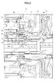
- Sectional drawing which shows a part of automatic transmission which concerns on 1st Embodiment.
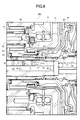
- Sectional drawing which shows the modification of the automatic transmission which concerns on 1st Embodiment.
- the schematic front view which shows the modification of the automatic transmission which concerns on 1st Embodiment.
- Sectional drawing which shows the modification of the automatic transmission which concerns on 2nd Embodiment.
- Sectional drawing which shows the modification of the automatic transmission which concerns on 3rd Embodiment.
- this vehicle drive device is a vehicle drive device suitable for being mounted on, for example, an FF (front engine / front drive) type vehicle, and the left and right directions in FIGS.
- the right side in the figure which is the drive source side of the engine or the like, is the “front side” or “the other side in the axial direction”, and the left side in the figure is the left side in the figure. It is referred to as “rear side” or “one side in the axial direction”.
- an automatic transmission 1 that is a vehicle drive device suitable for use in an FF type vehicle has a torque converter 2 having a lock-up clutch 2 a disposed on the front side, and a rear side.
- a transmission mechanism 3 a countershaft portion 4 and a differential portion 5 are arranged.
- the torque converter 2 is disposed on an axis centering on the input shaft 7A of the transmission mechanism 3 that is coaxial with the output shaft 10 of an engine (not shown), for example, and the transmission mechanism 3 is coaxial with the input shaft 7A.
- the transmission mechanism 3 is coaxial with the input shaft 7A.
- the counter shaft portion 4 is disposed on a counter shaft 12 which is on an axis parallel to the input shaft 7A and the central shaft 7B, and the differential portion 5 is arranged on the left and right drive shafts 15a on an axis parallel to the counter shaft 12. , 15b.
- the skeleton diagram shown in FIG. 1 shows the automatic transmission 1 in a plan view, and shows an input shaft 7A, a central shaft 7B, a counter shaft 12, and left and right drive shafts 15a and 15b. Is a triangular positional relationship in a side view.
- the transmission mechanism 3 is provided with an input shaft 7A to which rotation from the engine is transmitted via the torque converter 2, and a central shaft 7B connected and arranged on the rear side of the input shaft 7A. That is, in the automatic transmission 1, the input shaft 7 in a broad sense is configured by the input shaft 7A and the central shaft 7B.
- the speed change mechanism 3 is provided with a planetary gear DP on the input shaft 7A and a planetary gear unit PU on the center shaft 7B.
- the planetary gear DP includes a first sun gear S1, a first carrier CR1, and a first ring gear R1, and the first carrier CR1 is engaged with a pinion gear P2 and a first ring gear R1 that mesh with the first sun gear S1.
- This is a so-called double pinion planetary gear having meshing pinion gears P1 in mesh with each other.
- the planetary gear unit PU has a second sun gear S2, a third sun gear S3, a second carrier CR2, and a second ring gear R2 as four rotating members, and the second carrier CR2 includes a third sun gear.
- This is a so-called Ravigneaux type planetary gear having a long pinion gear P3 meshing with S3 and the second ring gear R2 and a short pinion gear P4 meshing with the second sun gear S2 in mesh with each other.
- the rotation of the first sun gear S1 of the planetary gear DP is fixed with respect to the case 6.
- the first carrier CR1 is connected to the input shaft 7A so as to be the same rotation as the rotation of the input shaft 7A (hereinafter referred to as “input rotation”), and is connected to the fourth clutch C-4.
- the first ring gear R1 is decelerated by the input rotation being decelerated by the fixed first sun gear S1 and the first carrier CR1 that rotates, and the first clutch C-1 (clutch Device) and the third clutch C-3.
- the third sun gear S3 of the planetary gear unit PU is connected to the first brake B-1 and can be fixed to the case 6, and the fourth clutch C-4 and the third clutch C-3. , And the input rotation of the first carrier CR1 through the fourth clutch C-4 and the decelerated rotation of the first ring gear R1 through the third clutch C-3 can be input. ing.
- the second sun gear S2 is connected to the first clutch C-1, so that the reduced rotation of the first ring gear R1 can be input.
- the second carrier CR2 is connected to the second clutch C-2 to which the rotation of the input shaft 7A is input via the center shaft 7B, and the input rotation is input to the second carrier CR2 via the second clutch C-2.
- it is connected to the one-way clutch F-1 and the second brake B-2, and is restricted from rotating in one direction with respect to the case 6 via the one-way clutch F-1, The rotation is freely fixable (lockable) via the second brake B-2.
- the second ring gear R2 is connected to a counter gear 8 that is rotatably supported with respect to a center support member 19 (see FIG. 3) fixed to the transmission case.
- the counter gear 8 meshes with a counter driven gear 11 fixed on the counter shaft 12 of the counter shaft portion 4, and the counter shaft 12 is connected with an output gear 12 a formed on the outer peripheral surface.
- the gear 14 of the differential portion 5 is engaged.
- the gear 14 is fixed to the differential gear 13 and is connected to the left and right drive shafts 15 a and 15 b via the differential gear 13.
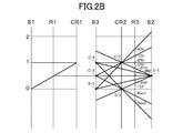
- the automatic transmission 1 configured as described above includes the first to fourth clutches C-1 to C-4, the first and second brakes B-1 and B-2, the one-way shown in the skeleton of FIG. As shown in the engagement table of FIG. 2A and the velocity diagram of FIG.
- the clutch F-1 is a plurality of friction engagement elements, ie, first to fourth clutches C-1 to C-4, first and By selectively engaging the second brakes B-1 and B-2 and the one-way clutch F-1, the first to third sun gears S1 to S3 and the first to fourth pinion gears which are a plurality of rotating elements P1 to P4, first and second ring gears R1 and R2, and first and second carriers CR1 and CR2 are controlled in rotation state, so that the first forward speed (1st) to the eighth forward speed (8th) and the reverse 1 The speed range from the first speed (Rev1) to the second reverse speed (Rev2) is achieved, and the speed input to the input shaft 7 is achieved. And shifting by rotating the counter gear 8, is output to the counter shaft portion 4.
- first to fourth clutches C-1 to C-4 first and
- the speed change mechanism 3 includes a center shaft 7B that is spline-engaged with the input shaft 7A at the center thereof.
- the front side of the central shaft 7B is rotatably supported by the case 6 via the input shaft 7A, and the rear side of the central shaft 7B is rotatable by a boss formed on the case 6 via a needle bearing. It is supported by.
- the planetary gear unit PU described above is disposed on the opposite side of the center support member 19 with respect to the counter gear 8 with the central shaft 7B as the center.
- a sleeve 31 (first rotating member) formed so as to extend from the main body of the second sun gear S2 (gear) to the other side in the axial direction is connected to the bush b1. Via the central axis 7B. That is, the sleeve 31 is disposed on one side in the axial direction of the input shaft 7A.
- a spline 31s (first spline) is formed on the front side of the sleeve 31, and a first peripheral surface 31a is formed on one side in the axial direction with respect to the spline 31s, that is, on the rear side of the spline 31s. Also, a first step portion 31b having a step shape in the radial direction is formed between the spline 31s and the first peripheral surface 31a.
- the sleeve 31 is formed with a third circumferential surface 31c alongside the first circumferential surface 31a on one axial side of the first circumferential surface 31a.
- the third peripheral surface 31c is a smooth peripheral surface with low surface roughness.
- the sleeve 31 is spline-engaged with a spline 32s (second spline) of the connecting member 32 (second rotating member) connected to the first clutch C-1 (see FIG. 1) described above, and the spline engaging portion S. Is forming.
- the connecting member 32 has splines 32s formed on the inner peripheral surface of the thick portion 32g having a thickness on the outer peripheral side in the radial direction. Moreover, the connection member 32 has the thin part 32b whose thickness of radial direction is thinner than the thick part 32g in the axial direction one side of the thick part 32g. On the inner peripheral surface of the thin-walled portion 32b, the groove portion 33 is recessed with respect to the first peripheral surface 31a in the radial direction, that is, recessed from the radially inner peripheral side toward the outer peripheral side, and a tolerance ring 40 (described later) is disposed. Is formed. That is, in the connecting member 32, the spline 32s and the groove portion 33 are formed side by side in the axial direction.
- the spline 32s and the groove 33 do not necessarily have to be formed adjacent to each other, but may be formed in the order adjacent to each other in the axial direction when viewed from the radial direction.
- the groove portion 33 may be formed at a position different from the position formed in the connecting member 32 in the radial direction.
- the connecting member 32 is compared with the case where the spline 32s is formed in the thin part 32b.
- the durability against the torque transmitted from the spline 31s of the sleeve 31 can be improved.
- the first sun gear S2 serves as a first friction engagement element via a spline engagement portion S in which the spline 31s of the sleeve 31 and the spline 32s of the connecting member 32 are spline engaged.
- the clutch C-1 is connected.
- the groove portion 33 is provided on the opposite side of the first clutch C-1 in the axial direction with respect to the spline 32s of the connecting member 32, and the first sun gear S2 through the spline engaging portion S through the first sun gear S2. It is provided at a position deviating from the route leading to the clutch C-1.
- the portion where the groove portion 33 of the connecting member 32 is provided can be a thin portion 32b having a radially outer peripheral thickness that is thinner than the thick portion 32g, thereby realizing a reduction in size in the radial direction. Can do.
- the connecting member 32 has a fitting portion 32e that is fitted to the third peripheral surface 31c of the sleeve 31 and has a low surface roughness on one side in the axial direction of the groove portion 33.
- the automatic transmission 1 can support the connecting member 32 with higher accuracy.
- the support accuracy of the connecting member 32 is improved as the surface roughness of the fitting portion 32e and the surface roughness of the third peripheral surface 31c are lower.
- the groove portion 33 has a bottom surface located between the first side surface 33b extending in the radial direction from the thin portion 32b of the connecting member 32 and the first side surface 33b and the second side surface 33c facing in the axial direction, facing the first circumferential surface 31a.
- the second peripheral surface 32a is formed, and is formed on the connecting member 32 so that the radial length from the first peripheral surface 31a to the second peripheral surface 32a is the first distance W1.
- a tolerance ring 40 as an elastic member that frictionally contacts the first peripheral surface 31 a and the second peripheral surface 32 a of the sleeve 31 is disposed inside the groove portion 33.
- the first side surface 33b and the second side surface 33c do not necessarily have to be formed substantially parallel to the radial direction.
- the first side surface 33b and the second side surface 33c may be opposed to each other in the axial direction in a state where they are formed in a square shape. Good.
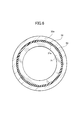
- FIG. 4 is a front view of the tolerance ring 40 in a state where the tolerance ring 40 is not attached to the groove 33, that is, the tolerance ring 40 is not elastically deformed.
- the tolerance ring 40 has a uniform unevenness in the radial direction when the elastic portion 40 b extending in the axial direction is bent in the radial direction, and when the elastic ring 40 is elastically deformed by being attached to the groove portion 33,
- the protruding surface 40a (first contact portion) protruding inward in the direction is in frictional contact with the first peripheral surface 31a
- the elastic portion 40b (second contact portion) having a thickness in the radial direction is in frictional contact with the second peripheral surface 32a. Is configured to do.
- the tolerance ring 40 includes a frictional force between the protruding surface 40a and the first peripheral surface 31a generated by its own elastic force generated by elastic deformation, an elastic portion 40b and a second peripheral surface 32a.
- the sleeve 31 and the connecting member 32 are engaged with each other by the frictional force between them.
- the both ends of the axial direction are the elastic parts 40b, respectively.
- the tolerance ring 40 is bent so that the radial length from the elastic portion 40b to the protruding surface 40a becomes the second distance W2 in a state where the tolerance ring 40 is not attached to the groove portion 33.
- the tolerance ring 40 has an extension 40c extending in the radial direction at one end in the axial direction and at the other end in the axial direction when attached to the groove 33.
- the second distance W2 is longer than the first distance W1, which is the length in the radial direction from the first peripheral surface 31a to the second peripheral surface 32a shown in FIG.
- the tolerance ring 40 is attached to the groove portion 33, the protruding surface 40a is brought into frictional contact with the first peripheral surface 31a and the elastic portion 40b is The frictional force between the projecting surface 40a and the first peripheral surface 31a generated by its own elastic force when it comes into frictional contact with the two peripheral surfaces 32a, and the frictional force between the elastic part 40b and the second peripheral surface 32a
- the sleeve 31 and the connecting member 32 are engaged, and the occurrence of play between the sleeve 31 and the connecting member 32 can be reduced.
- the connecting member 32 is formed with a spline 32s and a groove portion 33 arranged side by side, and a second step portion 32c having a radial step shape is formed between the spline 32s and the groove portion 33.
- the second step portion 32 c of the connecting member 32 is in contact with the first step portion 31 b of the sleeve 31.
- the automatic transmission 1 can position the connecting member 32 by bringing the second step portion 32c into contact with the first step portion 31b when the connecting member 32 is assembled.
- the automatic transmission 1 can position the tolerance ring 40 by disposing the tolerance ring 40 in the groove 33.
- the automatic transmission 1 can prevent the tolerance ring 40 disposed in the groove portion 33 from being separated into the automatic transmission 1 from the groove portion 33 due to an excessive load, a repeated load, or the like.
- the elastic portion 40b of the tolerance ring 40 having a thickness in the radial direction abuts on the first side surface 33b or the second side surface 33c, so that the axial direction of the tolerance ring 40 is increased. Can be restricted.
- the connecting member 32 has a groove portion 33 at a position away from the torque transmission path from the third sun gear S3 to the first clutch C-1 via the spline engaging portion S, that is, the first clutch C. -1 and the groove portion 33 are formed with a second spline.
- the connecting member 32 has a wall portion 32d which is formed at a different radial position of the spline 32s, that is, radially outward (outer peripheral surface) and extends radially outward.
- the wall portion 32d constitutes an end surface on one side in the axial direction of the thick portion 32g.
- the position of the wall portion 32d is not limited to the outer side in the radial direction of the spline 32s, but may be formed on the outer side in the radial direction of the groove portion 33.
- the connecting member 32 is configured such that a part of the groove portion 33 is formed in the thick portion 32g.
- the connecting member 32 extends to the other side (front side) in the axial direction, and the hydraulic servo 20 of the first clutch C-1 is disposed on the front side to be extended.
- the first clutch C-1 includes a friction plate composed of an outer friction plate and an inner friction plate, and a hydraulic servo 20 for connecting and disconnecting the friction plate.
- the friction plate is connected to the first ring gear R1.
- the hydraulic servo 20 is disposed on the inner peripheral side of the friction plate. That is, the first clutch C-1 has a clutch drum 32f that contains the hydraulic servo 20.
- the connecting member 32 is a shaft member that integrally extends from a clutch drum 32 f as a friction member of the first clutch C- 1 including the hydraulic servo 20.
- the automatic transmission 1 is integrally formed from the clutch drum 32f and the sleeve 31 having the second sun gear S2 having the smallest rotation radius on the one side in the axial direction among the planetary gear DP and the planetary gear unit PU of the transmission mechanism 3.
- a tolerance ring 40 is attached to the connecting member 32 which is a shaft member extending in the direction. That is, in the automatic transmission 1, the explosion vibration from the engine is easily transmitted to the input shaft 7A and the central shaft 7B connected thereto, and the side closer to the members supported by the input shaft 7A and the central shaft 7B has the explosion vibration. easily influenced.
- the automatic transmission 1 is spline-engaged with the sleeve 31 having the second sun gear S2 on the one side in the axial direction, which is the rotating element that is most affected by the explosion vibration of the engine due to the small turning radius.
- This is a case where the first clutch C-1 is released by engaging the sleeve 31 and the connecting member 32 by the elastic force of the tolerance ring 40 with the vibration of the connecting member 32 transmitted further amplified. And the generation of sound can be reduced. Further, since the vibration of the connecting member 32 can be reduced when the first clutch C-1 is released, the vibration transmitted from the second sun gear S2 to the first clutch C-1 can also be reduced.
- a third sun gear S3 (third rotating member) formed in a sleeve shape via the bush b2 is disposed so as to be rotatable relative to the central shaft 7B. Further, the third sun gear S3 has a groove portion of the connecting member 32 as a position facing the wall portion 32d of the connecting member 32 on the other axial side (front side) from the main body portion 34a having a tooth surface formed on the radially outer peripheral side. 33 has an extension 34b extended to the outside in the radial direction.
- the third sun gear S3 is axially positioned and regulated with respect to the second sun gear S2 via a thrust bearing b3 disposed on one axial side, and between the wall 32d and the extension 34b. Positioning is regulated in the axial direction with respect to the connecting member 32 via a thrust bearing b4 as a bearing member disposed in the shaft.
- the thrust bearing b4 can be disposed at a position where the sleeve 31 and the connecting member 32 overlap with the spline engaging portion S with which the sleeve 31 and the connecting member 32 are spline engaged in the axial direction as viewed from the radial direction. Therefore, the automatic transmission 1 can be provided with the sleeve 31 that engages with the spline and the tolerance ring 40 that can engage the connecting member 32, but the axial size of the automatic transmission 1 is large. Can be prevented.
- the thrust bearing b4 is disposed at a position overlapping the groove portion 33 in the axial direction when viewed from the radial direction. Also in this case, the automatic transmission 1 can obtain the same effect as the case where the wall portion 32d is formed on the radially outer side of the spline engaging portion S.
- the automatic transmission 1 is configured such that the tolerance ring 40 can be disposed on one side in the axial direction of the spline engaging portion S, the automatic transmission 1 is provided on one side in the axial direction of the input shaft 7A that is spline engaged with the central shaft 7B.
- the tip portion 35 which is an end portion can be disposed at a position adjacent to the end portion 31 d on the other axial side of the sleeve 31.
- the input shaft 7 ⁇ / b> A rotatably supports the connecting member 32 via a needle bearing b ⁇ b> 5 disposed between the outside of the distal end portion 35 and the connecting member 32.
- the connecting member 32 is formed on one side in the axial direction of the groove portion 33 and the fitting portion 32e having a low surface roughness is fitted to the third peripheral surface 31c having a low surface roughness.
- the connecting member 32 is supported on the input shaft 7A via the needle bearing b5 on the other axial side of the spline engaging portion S.
- the second sun gear S2 and the connecting member 32 can be disposed on substantially the same axis, and the first clutch C-1 and the first clutch C-1 are connected to each other. It is possible to suppress the swaying vibration of the connecting member 32 that is drivingly connected.
- the automatic transmission 1 has the second sun gear S2 that rotates at the highest speed at the highest gear, and rotates at a speed that is at least twice that of the input shaft 7;
- the first clutch C-1 is released. Therefore, in the automatic transmission 1, when the sixth forward speed to the eighth forward speed are achieved, the sleeve 31 having the second sun gear S2 on one side in the axial direction, and the connecting member 32 that is spline engaged with the sleeve 31 are provided. Are rotated by a third pinion gear P3 that is drivingly connected to the second sun gear S2, but the spline engaging portion S is obtained by coupling the sleeve 31 and the connecting member 32 by the elastic force of the tolerance ring 40. Thus, the vibration generated between the sleeve 31 and the connecting member 32 engaged with the spline can be reduced, and the generation of sound can be reduced.
- the elastic member provided with the tolerance ring 40 has been described as an example.
- the present invention is not limited thereto, and the first peripheral surface 31a, such as the ring-shaped rubber ring 50 shown in FIG. And the second peripheral surface 32a, and any member that engages the sleeve 31 and the connecting member 32 by elastic force may be used.
- the rubber ring 50 and the first peripheral surface are formed by making the first peripheral surface 31a of the sleeve 31 polygonal as shown in FIG.
- the lubricating oil is supplied into the groove portion 330 from the oil passage c3 as the first lubricating hole provided in the sleeve 310. Can do. Further, since the first step portion 310b and the second step portion 320c of the connecting member 320 are not in contact with each other, in the speed change mechanism 300, the lubricating oil supplied into the groove portion 330 is supplied to the spline engaging portion S. be able to.
- the centrifugal force generated by the rotation of the sleeve 310 and the connecting member 320 is caused by the elastic portion of the tolerance ring 40. Since it acts in the direction which sticks 40b to the 2nd peripheral surface 32a, the movement of the tolerance ring 40 in the axial direction can be controlled more reliably.
- the connecting member 320 is provided on the radially outer side than the sleeve 310, and is located in an axial range where the protruding surface 40 a of the tolerance ring 40 is located in the radial view. 2 It has the oil path c4 as a lubrication hole.
- the drive device can supply lubricating oil to the groove portion 330, and wear of the tolerance ring 40 can be prevented.
- a driving device according to a third embodiment will be described with reference to FIG.
- This embodiment is different from the first and second embodiments in that the groove portion 331 is provided in the sleeve 311 having the second sun gear S2 in the speed change mechanism 301, but the other configurations are the first. Since it is the same as that of 2nd Embodiment, the same structure is abbreviate
- the connecting member 321 (first rotating member) has a first peripheral surface 321a formed side by side with the first spline 321s on the right side in FIG. 8 (one side in the axial direction).
- the sleeve 311 (second rotating member) is formed side by side with the second spline 311s and the second spline 311s that are spline engaged with the first spline 321s to form the spline engaging portion SA.
- the driving device can reduce the play and the generation of sound by enabling the rotating members engaged with the spline to be engaged with each other by the tolerance ring 40, and the tolerance ring 40 can be formed in the groove portion.
- the tolerance ring 40 can be positioned when it is disposed in the 331.
- the vehicle drive device (1) includes the first spline (31s, 321s) and the first circumferential surface (31a) formed side by side with the first spline (31s, 321s) in the axial direction. , 321a), and a first rotating member (31, 310, 321) having Second splines (32s, 311s) that form spline engaging portions (S, SA) by spline engagement with the first splines (31s, 321s), and the second splines (32s, 311s) in the axial direction.
- a second side surface formed side by side, recessed in the radial direction with respect to the first peripheral surface (31a, 321a) and facing the first side surface (33b, 331b) and the first side surface (33b, 331b) ( 33c, 331c) has a groove portion (33, 331) having a bottom surface located between the first peripheral surface (31a, 321a) and a second peripheral surface (32a, 311a) radially opposed to the first peripheral surface (31a, 321a).
- Two rotating members (32, 311, 320) It is disposed in the groove (33, 330, 331) and generates an elastic force in the radial direction between the first rotating member (31, 310, 321) and the second rotating member (32, 311, 320).
- An elastic member (40) to be The elastic member (40) generates a circumferential frictional resistance between the first peripheral surface (31a, 321a) and the second peripheral surface (32a, 311a) by the elastic force.
- the said elastic member (40) contacts the said 1st surrounding surface (31a, 321a) in the state before attaching to the said groove part (33,330,331).
- the radial length (W2) between the surface and the surface in contact with the second peripheral surface (32a, 311a) is from the first peripheral surface (31a, 321a) to the second peripheral surface (32a, 311a). It is longer than the length (W1) in the radial direction and is elastically deformed and attached to the groove (33, 330, 331).
- the elastic member (40) when the elastic member (40) is attached to the groove (33, 330, 331), the elastic member (40) is elastically deformed in the radial direction, so that the first rotating member (31, 310, 321) and the second rotating member ( 32, 311 and 320) can be engaged, and the occurrence of play between the first rotating member (31, 310, 321) and the second rotating member (32, 311, 320) can be reduced.
- the said elastic member (40) has a 1st contact part (40a) and a 2nd contact part (40b),
- the first contact portion (40a) bends from the first contact portion (40a) toward the first peripheral surface (31a, 310a, 321a) to the first peripheral surface (31a, 310a, 321a). Touch,
- the second contact portion (40b) contacts the second peripheral surface (32a, 311a, 320a), Both ends of the elastic member (40) in the axial direction are the second contact portions (40b).
- the elastic member (40) is loaded and moved in the axial direction, the second contact portion (40b) of the elastic member (40) comes into contact with the groove portions (33, 330, 331), so that the elastic member (40) is elastic.
- the movement of the member (40) in the axial direction can be restricted.
- the said 1st rotation member (310) has a 1st lubrication hole (c3) which supplies oil to the said groove part (330),
- the second rotating member (320) is provided on the radially outer side than the first rotating member (310), and is positioned within an axial range where the first contact portion (40a) is positioned in a radial view.
- a second lubricating hole (c4) is provided.
- lubricating oil can be supplied to the groove (330), and wear of the elastic member (40) can be prevented.
- one of the first rotating member (31, 310, 321) or the second rotating member (32, 311, 320) is connected to one side in the axial direction from a driving source.
- the first spline (31s, 321s) or the second spline (32s, 311s) is formed on the other side in the axial direction having a gear (S2) that can rotate with the rotation of the input shaft (7) for inputting rotation.
- Rotating member The other of the first rotating member (31, 310, 321) or the second rotating member (32, 311, 320) has a friction member (32f) of a predetermined friction engagement element (C-1).
- the rotation input from the input shaft (7) is transmitted to the second rotation member (31, 310, 321) via the first rotation member (31, 310, 321).
- the elastic member (40) generates vibration and sound generated in the spline engaging portion (S, SA) and the second rotation member (31, 310, 321). It can be reduced by engaging the rotating members (32, 311, 320).
- the second rotating member (32, 311, 320) in the axial direction includes the gear (S2) or the second rotating member (32, 311, 320).
- the second spline (32s, 311s) is formed between the friction member (32f) of the predetermined friction engagement element (C-1) and the groove (33, 330, 331).
- the second rotating member (320) The vicinity of the axial end of the groove (330) is not in contact with the first rotating member (310),
- the friction member (32f) of the predetermined friction engagement element (C-1) is provided, the friction member (32-1) is disposed on the radially outer side than the first rotation member (310).
- the centrifugal force generated by the rotation of the first rotating member (310) and the second rotating member (320) attaches the second contact portion (40b) of the elastic member (40) to the second peripheral surface (32a). Since it acts on a direction, the movement of the elastic member (40) in the axial direction can be more reliably regulated.
- a plurality of rotating elements (31, 32, 310, 311, 320, 321, S1 to S3, P1 to P4, R1, R2, CR1, CR2) and the plurality of rotating elements
- a plurality of friction engagement elements (C-1 to C-4) drivingly connected to the rotation elements (31, 32, 310, 311, 320, 321, S1 to S3, P1 to P4, R1, R2, CR1, CR2) , B-1, B-2, F-1) and selectively selecting the plurality of friction engagement elements (C-1 to C-4, B-1, B-2, F-1) Is engaged to control the rotational state of the plurality of rotating elements (31, 32, 310, 311, 320, 321, S1 to S3, P1 to P4, R1, R2, CR1, CR2), and a plurality of shift stages.
- the first rotating member (31, 310, including a state of rotating at a higher speed than the input shaft (7)) is included.
- 321) and the second rotating member (32, 311, 320) are coupled by the elastic force of the elastic member (40), so that the first rotating member (31, which is spline engaged with the spline engaging portion (S, SA)).
- 310, 321) and the second rotating member (32, 311, 320) can be reduced, and the generation of sound can be reduced.
- the first rotating member (31, 310, 321) and the second rotating member (32, 311, 320) include the plurality of rotating elements (31, 32, 310). , 311, 320, 321, S1 to S3, P1 to P4, R1, R2, CR1, and CR2).
- , 310, 321) and the second rotating member (32, 311, 320) are coupled by the elastic force of the elastic member (40), so that the spline engaging portion (S, SA) engages in the spline engagement. Vibration generated between the member (31, 310, 321) and the second rotating member (32, 311, 320) can be reduced, and generation of sound can be reduced.
- a plurality of rotating elements (31, 32, 310, 311, 320, 321, S1 to S3, P1 to P4, R1, R2, CR1, CR2) and the plurality of rotating elements
- a plurality of friction engagement elements (C-1 to C-4) drivingly connected to the rotation elements (31, 32, 310, 311, 320, 321, S1 to S3, P1 to P4, R1, R2, CR1, CR2) , B-1, B-2, F-1) and selectively selecting the plurality of friction engagement elements (C-1 to C-4, B-1, B-2, F-1) Is engaged to control the rotational state of the plurality of rotating elements (31, 32, 310, 311, 320, 321, S1 to S3, P1 to P4, R1, R2, CR1, CR2), and a plurality of shift stages.
- the gear (S2) is included in the plurality of rotating elements (31, 32, 310, 311, 320, 321, S1 to S3, P1 to P4, R1, R2, CR1, CR2),
- the predetermined friction engagement element (C-1) is included in the plurality of friction engagement elements (C-1 to C-4, B-1, B-2, F-1), and the speed change mechanism (3 , 300, 301) are released when the maximum gear is achieved,
- the first rotating member (31, 310, 321) and the second rotating member (32, 311, 320) are idly rotated by the gear (S2) in the state of the highest gear.
- the speed change mechanism (3, 300, 301) achieves the maximum speed and the predetermined friction engagement element (C-1) is released, the first rotation member (31) is rotated idly by the gear (S2). , 310, 321) and the second rotating member (32, 311, 320) are coupled by the elastic force of the elastic member (40), so that the spline engaging portion (S, SA) engages in the spline engagement. Vibration generated between the member (31, 310, 321) and the second rotating member (32, 311, 320) can be reduced, and generation of sound can be reduced.
- the gear (S2) included in one of the first rotating member (31, 310, 321) or the second rotating member (32, 311, 320) is a planetary gear ( PU) sun gear
- the predetermined friction engagement element (C-1) is a clutch device (C-1) having a clutch drum (32f) containing a hydraulic servo (20)
- the first rotating member (31, 310, 321) or the second rotating member (32, 311, 320) having the predetermined friction engagement element (C-1) is connected to the predetermined friction engagement element (C-1).
- the first rotating member (31, 310, 321) or the second rotating member having a gear (S2) on the one side in the axial direction which is the rotating element that is most affected by the explosion vibration of the engine due to the small rotation radius.
- the first rotating member (31, 310, 321) or the second rotating member having a predetermined friction engagement element (C-1) which is amplified and transmitted by being spline engaged with one of (32, 311, 320)
- the first rotation member (31, 310, 321) and the second rotation member (32, 311, 320) are engaged by the other vibration of (32, 311, 320) by the elastic force of the elastic member (40). Can reduce the generation of sound. Further, since the vibration of the second rotating member (32, 311, 320) can be reduced, the vibration transmitted from the gear (S2) to the clutch device (C-1) can also be reduced.
- the automatic transmission 1 is described as an example that achieves, for example, the eighth forward speed and the second reverse speed.
- the present invention is not limited to this. It may achieve a fast gear and a reverse gear.
- the tolerance ring 40 is disposed between the sleeve 31 and the connecting member 32, but the present invention is not limited to this.
- the tolerance ring 40 only needs to be disposed between the rotating members that are engaged with the spline.
- the tolerance ring 40 is formed between two rotating members that rotate faster than the input shaft 7.
- the third sun gear S3 that rotates at a higher speed than the input shaft 7 in the fifth forward speed and the spline 36s that is spline-engaged with the spline 34bs of the extension 34b are provided.
- a tolerance ring 40 may be disposed between the connecting member 36 connected to the third clutch C-3 on the other axial side.
- the automatic transmission 1 is connected only to the engine.
- a vehicle drive for a hybrid vehicle equipped with a motor / generator instead of the torque converter 2 is used. It may be a device.
- the vehicle drive device can be mounted on a vehicle such as a passenger car or a truck, and in particular, it is required to reduce the occurrence of rattling and noise that occur when the rotating members that rotate at high speed are spline-engaged. It is suitable for use in things.
- Vehicle drive system (automatic transmission) 3 Transmission mechanism 31 First rotating member (sleeve) 31a 1st surrounding surface 31b 1st step part 31c 3rd surrounding surface 31s 1st spline (spline) 32 Second rotating member (connecting member) 32a Second peripheral surface 32f Friction member (clutch drum) 32s 2nd spline (spline) 33 Groove portion 33b First side surface 33c Second side surface 34a Main body portion 34b Extension portion 40 Elastic member (tolerance ring) 40a First contact portion (protruding surface) 40b 2nd contact part (elastic part) 40c Extension 50 Elastic member (rubber ring) 300 Transmission mechanism 301 Transmission mechanism 310 First rotating member (sleeve) 311 Second rotating member (sleeve) 311a Second peripheral surface 311s Second spline (spline) 320 Second rotating member (connecting member) 321 First rotating member (connecting member) 321a First circumferential surface 321s First spline (spline
Landscapes
- Engineering & Computer Science (AREA)
- General Engineering & Computer Science (AREA)
- Mechanical Engineering (AREA)
- Structure Of Transmissions (AREA)
- Mechanical Operated Clutches (AREA)
- General Details Of Gearings (AREA)
Abstract
Description
前記第1スプラインとスプライン係合してスプライン係合部を形成する第2スプラインと、軸方向に前記第2スプラインと並んで形成され、径方向において前記第1周面に対して凹み、かつ、第1側面と前記第1側面と対向する第2側面との間に位置する底面が前記第1周面と径方向に対向する第2周面となる溝部と、を有する第2回転部材と、
前記溝部に配設され、前記第1回転部材と前記第2回転部材との間で径方向に弾性力を生じさせる弾性部材と、を備え、
前記弾性部材は、前記弾性力によって前記第1周面と前記第2周面との間に周方向の摩擦抵抗を生じさせる。
以下、第1の実施の形態を図1乃至図4に沿って説明する。なお、本車両用駆動装置は、例えばFF(フロントエンジン・フロントドライブ)タイプ等の車両に搭載されて好適な車両用駆動装置であり、図1、図3中における左右方向が実際の車両搭載状態における左右方向(或いは左右逆方向)に対応するが、説明の便宜上、エンジン等の駆動源側である図中右方側を「前方側」又は「軸方向他方側」、図中左方側を「後方側」又は「軸方向一方側」というものとする。
次に、第2の実施形態に係る駆動装置を、図7に沿って説明する。本実施形態は、変速機構300において、溝部330の構造がスリーブ310と連結部材320とによって略密閉されていない点で第1の実施形態と異なっているが、それ以外の構成は第1の実施形態と同様であるので、同様の構成は符号を同じくして詳細な説明を省略する。
次に、第3の実施形態に係る駆動装置を、図8に沿って説明する。本実施形態は、変速機構301において、溝部331が第2のサンギヤS2を有するスリーブ311に設けられている点で第1、第2の実施形態と異なっているが、それ以外の構成は第1、第2の実施形態と同様であるので、同様の構成は符号を同じくして詳細な説明を省略する。
以上説明したように、本車両用駆動装置(1)は、第1スプライン(31s,321s)と、軸方向に前記第1スプライン(31s,321s)と並んで形成された第1周面(31a,321a)と、を有する第1回転部材(31,310,321)と、
前記第1スプライン(31s,321s)とスプライン係合してスプライン係合部(S,SA)を形成する第2スプライン(32s,311s)と、軸方向に前記第2スプライン(32s,311s)と並んで形成され、径方向において前記第1周面(31a,321a)に対して凹み、かつ、第1側面(33b,331b)と前記第1側面(33b,331b)と対向する第2側面(33c,331c)との間に位置する底面が前記第1周面(31a,321a)と径方向に対向する第2周面(32a,311a)となる溝部(33,331)と、を有する第2回転部材(32,311,320)と、
前記溝部(33,330,331)に配設され、前記第1回転部材(31,310,321)と前記第2回転部材(32,311,320)との間で径方向に弾性力を生じさせる弾性部材(40)と、を備え、
前記弾性部材(40)は、前記弾性力によって前記第1周面(31a,321a)と前記第2周面(32a,311a)との間に周方向の摩擦抵抗を生じさせる。
前記第1接触部(40a)は、前記第1接触部(40a)から前記第1周面(31a,310a,321a)に向かって屈曲して前記第1周面(31a,310a,321a)に接触し、
前記第2接触部(40b)は、前記第2周面(32a,311a,320a)に接触し、
前記弾性部材(40)は、軸方向の両端部がそれぞれ前記第2接触部(40b)である。
前記第2回転部材(320)は、前記第1回転部材(310)よりも径方向外側に設けられ、径方向視において前記第1接触部(40a)が位置する軸方向の範囲内に位置する第2潤滑孔(c4)を有する。
前記第1回転部材(31,310,321)又は前記第2回転部材(32,311,320)の他方は、所定摩擦係合要素(C-1)の摩擦部材(32f)を有する。
前記溝部(330)の軸方向の端部近傍が前記第1回転部材(310)と非接触であり、
前記所定摩擦係合要素(C-1)の前記摩擦部材(32f)を有する場合、前記第1回転部材(310)よりも径方向外側に配設される。
駆動源からの回転を前記変速機構(3,300,301)に入力する入力軸(7)と、を備え、
前記歯車(S2)は、前記複数の回転要素(31,32,310,311,320,321,S1~S3,P1~P4,R1,R2,CR1,CR2)に含まれ、
前記所定摩擦係合要素(C-1)は、前記複数の摩擦係合要素(C-1~C-4,B-1,B-2,F-1)に含まれ、
前記第1回転部材(31,310,321)及び前記第2回転部材(32,311,320)は、
前記所定摩擦係合要素(C-1)が解放された場合に、前記歯車(S2)によって空転回転され、
前記所定摩擦係合要素(C-1)が解放され前記歯車(S2)によって空転回転された場合に、前記入力軸(7)よりも高速回転する状態を含む。
駆動源からの回転を前記変速機構(3,300,301)に入力する入力軸(7)と、を備え、
前記歯車(S2)は、前記複数の回転要素(31,32,310,311,320,321,S1~S3,P1~P4,R1,R2,CR1,CR2)に含まれ、
前記所定摩擦係合要素(C-1)は、前記複数の摩擦係合要素(C-1~C-4,B-1,B-2,F-1)に含まれ、前記変速機構(3,300,301)が最高変速段を達成する場合に解放され、
前記第1回転部材(31,310,321)及び前記第2回転部材(32,311,320)は、前記最高変速段の状態で前記歯車(S2)によって空転回転される。
前記所定摩擦係合要素(C-1)は、油圧サーボ(20)を内包するクラッチドラム(32f)を有するクラッチ装置(C-1)であり、
前記所定摩擦係合要素(C-1)を有する前記第1回転部材(31,310,321)又は前記第2回転部材(32,311,320)は、前記所定摩擦係合要素(C-1)のクラッチドラム(32f)から一体的に伸びる軸部材である。
3 変速機構
31 第1回転部材(スリーブ)
31a 第1周面
31b 第1段部
31c 第3周面
31s 第1スプライン(スプライン)
32 第2回転部材(連結部材)
32a 第2周面
32f 摩擦部材(クラッチドラム)
32s 第2スプライン(スプライン)
33 溝部
33b 第1側面
33c 第2側面
34a 本体部
34b 延長部
40 弾性部材(トレランスリング)
40a 第1接触部(突出面)
40b 第2接触部(弾性部)
40c 延長部
50 弾性部材(ゴムリング)
300 変速機構
301 変速機構
310 第1回転部材(スリーブ)
311 第2回転部材(スリーブ)
311a 第2周面
311s 第2スプライン(スプライン)
320 第2回転部材(連結部材)
321 第1回転部材(連結部材)
321a 第1周面
321s 第1スプライン(スプライン)
330 溝部
331 溝部
331b 第1側面
331c 第2側面
b4 軸受部材(スラストベアリング)
C-1 特定摩擦係合要素(第1のクラッチ)
c3 第1潤滑孔(油路)
c4 第2潤滑孔(油路)
S スプライン係合部
SA スプライン係合部
S2 歯車(第2のサンギヤ)
Claims (11)
- 第1スプラインと、軸方向に前記第1スプラインと並んで形成された第1周面と、を有する第1回転部材と、
前記第1スプラインとスプライン係合してスプライン係合部を形成する第2スプラインと、軸方向に前記第2スプラインと並んで形成され、径方向において前記第1周面に対して凹み、かつ、第1側面と前記第1側面と対向する第2側面との間に位置する底面が前記第1周面と径方向に対向する第2周面となる溝部と、を有する第2回転部材と、
前記溝部に配設され、前記第1回転部材と前記第2回転部材との間で径方向に弾性力を生じさせる弾性部材と、を備え、
前記弾性部材は、前記弾性力によって前記第1周面と前記第2周面との間に周方向の摩擦抵抗を生じさせる、
車両用駆動装置。 - 前記弾性部材は、前記溝部に取り付けられる前の状態で、前記第1周面と接触する面と前記第2周面と接触する面との径方向の長さが、前記第1周面から前記第2周面までの径方向の長さよりも長く、弾性変形して前記溝部に取り付けられる、
請求項1に記載の車両用駆動装置。 - 前記弾性部材は、第1接触部と、第2接触部と、を有し、
前記第1接触部は、前記第2接触部から前記第1周面に向かって屈曲して形成され、前記第1周面と接触し、
前記第2接触部は、前記第2周面と接触し、
前記弾性部材は、軸方向の両端部がそれぞれ前記第2接触部である、
請求項1又は請求項2に記載の車両用駆動装置。 - 前記第1回転部材は、前記溝部に油を供給する第1潤滑孔を有し、
前記第2回転部材は、前記第1回転部材よりも径方向外側に設けられ、径方向視において前記第1接触部が位置する軸方向の範囲内に位置する第2潤滑孔を有する、
請求項3に記載の車両用駆動装置。 - 前記第1回転部材又は前記第2回転部材の一方は、軸方向一方側に駆動源からの回転を入力する入力軸の回転に伴い回転可能な歯車を有し軸方向他方側に前記第1スプライン又は前記第2スプラインが形成される回転部材であり、
前記第1回転部材又は前記第2回転部材の他方は、所定摩擦係合要素の摩擦部材を有する、
請求項1乃至請求項4のいずれか1項に記載の車両用駆動装置。 - 前記第2回転部材は、軸方向において、前記第2回転部材が有する前記歯車又は前記所定摩擦係合要素と前記溝部との間に前記第2スプラインが形成される、
請求項5に記載の車両用駆動装置。 - 前記第2回転部材は、
前記溝部の軸方向の端部近傍が前記第1回転部材と非接触であり、
前記所定摩擦係合要素の前記摩擦部材を有する場合、前記第1回転部材よりも径方向外側に配設される、
請求項5又は請求項6に記載の車両用駆動装置。 - 複数の回転要素と、前記複数の回転要素に駆動連結される複数の摩擦係合要素と、を有し、前記複数の摩擦係合要素を選択的に係合することで前記複数の回転要素の回転状態を制御し複数の変速段を達成する変速機構と、
駆動源からの回転を前記変速機構に入力する入力軸と、を備え、
前記歯車は、前記複数の回転要素に含まれ、
前記所定摩擦係合要素は、前記複数の摩擦係合要素に含まれ、
前記第1回転部材及び前記第2回転部材は、
前記所定摩擦係合要素が解放された場合に、前記歯車によって空転回転され、
前記所定摩擦係合要素が解放され前記歯車によって空転回転された場合に、前記入力軸よりも高速回転する状態を含む、
請求項5乃至請求項7のいずれか1項に記載の車両用駆動装置。 - 前記第1回転部材及び前記第2回転部材は、前記複数の回転要素の中で最も高速回転可能である、
請求項8に記載の車両用駆動装置。 - 複数の回転要素と、前記複数の回転要素に駆動連結される複数の摩擦係合要素と、を有し、前記複数の摩擦係合要素を選択的に係合することで前記複数の回転要素の回転状態を制御し複数の変速段を達成する変速機構と、
駆動源からの回転を前記変速機構に入力する入力軸と、を備え、
前記歯車は、前記複数の回転要素に含まれ、
前記所定摩擦係合要素は、前記複数の摩擦係合要素に含まれ、前記変速機構が最高変速段を達成する場合に解放され、
前記第1回転部材及び前記第2回転部材は、前記最高変速段の状態で前記歯車によって空転回転される、
請求項5乃至請求項9のいずれか1項に記載の車両用駆動装置。 - 前記第1回転部材又は前記第2回転部材の一方が有する前記歯車は、プラネタリギヤのサンギヤであり、
前記所定摩擦係合要素は、油圧サーボを内包するクラッチドラムを有するクラッチ装置であり、
前記所定摩擦係合要素を有する前記第1回転部材又は前記第2回転部材の他方は、前記所定摩擦係合要素のクラッチドラムから一体的に伸びる軸部材である、
請求項8乃至請求項10のいずれか1項に記載の車両用駆動装置。
Priority Applications (3)
| Application Number | Priority Date | Filing Date | Title |
|---|---|---|---|
| DE112016001909.2T DE112016001909B4 (de) | 2015-06-30 | 2016-06-30 | Fahrzeugantriebsvorrichtung |
| JP2017526444A JP6634082B2 (ja) | 2015-06-30 | 2016-06-30 | 車両用駆動装置 |
| US15/570,791 US11009079B2 (en) | 2015-06-30 | 2016-06-30 | Vehicle drive apparatus |
Applications Claiming Priority (2)
| Application Number | Priority Date | Filing Date | Title |
|---|---|---|---|
| JP2015132225 | 2015-06-30 | ||
| JP2015-132225 | 2015-06-30 |
Publications (1)
| Publication Number | Publication Date |
|---|---|
| WO2017002948A1 true WO2017002948A1 (ja) | 2017-01-05 |
Family
ID=57607815
Family Applications (1)
| Application Number | Title | Priority Date | Filing Date |
|---|---|---|---|
| PCT/JP2016/069555 Ceased WO2017002948A1 (ja) | 2015-06-30 | 2016-06-30 | 車両用駆動装置 |
Country Status (4)
| Country | Link |
|---|---|
| US (1) | US11009079B2 (ja) |
| JP (1) | JP6634082B2 (ja) |
| DE (1) | DE112016001909B4 (ja) |
| WO (1) | WO2017002948A1 (ja) |
Families Citing this family (4)
| Publication number | Priority date | Publication date | Assignee | Title |
|---|---|---|---|---|
| JP6372455B2 (ja) * | 2015-09-07 | 2018-08-15 | トヨタ自動車株式会社 | 車両用動力伝達装置 |
| JP6341216B2 (ja) * | 2016-02-09 | 2018-06-13 | トヨタ自動車株式会社 | 車両の動力伝達装置 |
| DE102017204119A1 (de) * | 2017-03-13 | 2018-09-13 | Robert Bosch Gmbh | Aktor mit einer Antriebseinheit und einer Getriebeeinheit |
| CN113700835B (zh) * | 2021-09-28 | 2025-09-26 | 阿姆特(上海)新能源科技有限公司 | 主副箱变速器和车辆 |
Citations (4)
| Publication number | Priority date | Publication date | Assignee | Title |
|---|---|---|---|---|
| JP2003113918A (ja) * | 2001-10-05 | 2003-04-18 | Koyo Seiko Co Ltd | 無段変速機用ボールねじ装置 |
| JP2005047340A (ja) * | 2003-07-31 | 2005-02-24 | Favess Co Ltd | ステアリング装置 |
| JP2011214646A (ja) * | 2010-03-31 | 2011-10-27 | Aisin Aw Co Ltd | ロータ軸の支持構造 |
| JP2013190026A (ja) * | 2012-03-13 | 2013-09-26 | Aisin Aw Co Ltd | 変速装置 |
Family Cites Families (14)
| Publication number | Priority date | Publication date | Assignee | Title |
|---|---|---|---|---|
| US4793200A (en) * | 1987-11-19 | 1988-12-27 | Chrysler Motors Corporation | Reverse idler gear noise-reduction arrangement |
| JP3132209B2 (ja) * | 1992-12-17 | 2001-02-05 | トヨタ自動車株式会社 | スプライン軸継手 |
| JP3903499B2 (ja) | 1996-08-02 | 2007-04-11 | 日本ジョン・クレーン株式会社 | 高圧用メカニカルシール |
| JP2002101608A (ja) | 2000-09-20 | 2002-04-05 | Koyo Seiko Co Ltd | モータ及びこれを用いた電動パワーステアリング装置 |
| WO2003033463A2 (en) * | 2001-10-19 | 2003-04-24 | The Mclean Hospital Corporation | Multimerized enhancer domains for cell-specific expression |
| US20060046858A1 (en) * | 2004-08-26 | 2006-03-02 | Ronald Brissette | Driveshaft assembly with torque ring coupling |
| DE202006020107U1 (de) * | 2006-01-11 | 2007-12-06 | Gkn Driveline International Gmbh | Antriebsanordnung mit Toleranzring |
| JP5101357B2 (ja) | 2008-03-18 | 2012-12-19 | 三菱重工業株式会社 | 回転機械及び追設リング |
| JP5535992B2 (ja) * | 2011-07-15 | 2014-07-02 | 三菱重工業株式会社 | 電動過給圧縮機、その組立方法及び内燃機関 |
| US10749402B2 (en) | 2012-05-02 | 2020-08-18 | Mitsubishi Electric Corporation | Rotary electric machine |
| JP2014101924A (ja) | 2012-11-19 | 2014-06-05 | Aisin Aw Co Ltd | 自動変速機 |
| JP2015045398A (ja) | 2013-08-29 | 2015-03-12 | アイシン・エィ・ダブリュ株式会社 | 複列軸受 |
| JP6233324B2 (ja) * | 2015-02-03 | 2017-11-22 | トヨタ自動車株式会社 | 車両の回転軸の支持構造 |
| JP6222164B2 (ja) * | 2015-04-27 | 2017-11-01 | トヨタ自動車株式会社 | 車両の動力伝達構造 |
-
2016
- 2016-06-30 US US15/570,791 patent/US11009079B2/en active Active
- 2016-06-30 WO PCT/JP2016/069555 patent/WO2017002948A1/ja not_active Ceased
- 2016-06-30 DE DE112016001909.2T patent/DE112016001909B4/de active Active
- 2016-06-30 JP JP2017526444A patent/JP6634082B2/ja active Active
Patent Citations (4)
| Publication number | Priority date | Publication date | Assignee | Title |
|---|---|---|---|---|
| JP2003113918A (ja) * | 2001-10-05 | 2003-04-18 | Koyo Seiko Co Ltd | 無段変速機用ボールねじ装置 |
| JP2005047340A (ja) * | 2003-07-31 | 2005-02-24 | Favess Co Ltd | ステアリング装置 |
| JP2011214646A (ja) * | 2010-03-31 | 2011-10-27 | Aisin Aw Co Ltd | ロータ軸の支持構造 |
| JP2013190026A (ja) * | 2012-03-13 | 2013-09-26 | Aisin Aw Co Ltd | 変速装置 |
Also Published As
| Publication number | Publication date |
|---|---|
| US11009079B2 (en) | 2021-05-18 |
| US20180119746A1 (en) | 2018-05-03 |
| DE112016001909T5 (de) | 2018-01-11 |
| DE112016001909B4 (de) | 2026-01-22 |
| JPWO2017002948A1 (ja) | 2018-02-01 |
| JP6634082B2 (ja) | 2020-01-22 |
Similar Documents
| Publication | Publication Date | Title |
|---|---|---|
| JP4790608B2 (ja) | ダブルクラッチ変速機 | |
| US8545364B2 (en) | Gear set arrangement of a planetary transmission | |
| US8808134B2 (en) | Automatic transmission | |
| US7914413B2 (en) | Automatic transmission | |
| CN105705828B (zh) | 多挡变速器 | |
| JP6634082B2 (ja) | 車両用駆動装置 | |
| JP2014098402A (ja) | デュアルクラッチ式自動変速機 | |
| CN101583810B (zh) | 自动变速器 | |
| WO2012141056A1 (ja) | 変速装置 | |
| JP5440543B2 (ja) | 変速装置 | |
| CN101749335A (zh) | 自动变速器的活塞装置 | |
| CN104968974A (zh) | 动力传递装置 | |
| CN108603573A (zh) | 动力传递装置 | |
| JP2017198307A (ja) | 車両用動力伝達装置およびその製造方法 | |
| CN101248293B (zh) | 自动变速器中的压力油供给装置 | |
| JP2005113974A (ja) | 車輌用自動変速機 | |
| KR20230052004A (ko) | 전기차 변속기 | |
| WO2015075878A1 (ja) | 自動変速機 | |
| JP2017198306A (ja) | 車両用動力伝達装置およびその製造方法 | |
| JP2008089051A (ja) | プラネタリギヤ装置 | |
| JP5638101B2 (ja) | 自動変速機 | |
| JP2016061304A (ja) | 自動変速機 | |
| JP2005113970A (ja) | プラネタリギヤ装置 | |
| JP2018168930A (ja) | 変速機 | |
| JP5018215B2 (ja) | 自動変速機 |
Legal Events
| Date | Code | Title | Description |
|---|---|---|---|
| 121 | Ep: the epo has been informed by wipo that ep was designated in this application |
Ref document number: 16818056 Country of ref document: EP Kind code of ref document: A1 |
|
| ENP | Entry into the national phase |
Ref document number: 2017526444 Country of ref document: JP Kind code of ref document: A |
|
| WWE | Wipo information: entry into national phase |
Ref document number: 15570791 Country of ref document: US |
|
| WWE | Wipo information: entry into national phase |
Ref document number: 112016001909 Country of ref document: DE |
|
| 122 | Ep: pct application non-entry in european phase |
Ref document number: 16818056 Country of ref document: EP Kind code of ref document: A1 |
|
| WWG | Wipo information: grant in national office |
Ref document number: 112016001909 Country of ref document: DE |