WO2017002848A1 - 見守り情報共有システム - Google Patents
見守り情報共有システム Download PDFInfo
- Publication number
- WO2017002848A1 WO2017002848A1 PCT/JP2016/069257 JP2016069257W WO2017002848A1 WO 2017002848 A1 WO2017002848 A1 WO 2017002848A1 JP 2016069257 W JP2016069257 W JP 2016069257W WO 2017002848 A1 WO2017002848 A1 WO 2017002848A1
- Authority
- WO
- WIPO (PCT)
- Prior art keywords
- information
- unit
- person
- information terminal
- terminal
- Prior art date
- Legal status (The legal status is an assumption and is not a legal conclusion. Google has not performed a legal analysis and makes no representation as to the accuracy of the status listed.)
- Ceased
Links
Images





Classifications
-
- G—PHYSICS
- G08—SIGNALLING
- G08B—SIGNALLING SYSTEMS, e.g. PERSONAL CALLING SYSTEMS; ORDER TELEGRAPHS; ALARM SYSTEMS
- G08B25/00—Alarm systems in which the location of the alarm condition is signalled to a central station, e.g. fire or police telegraphic systems
- G08B25/01—Alarm systems in which the location of the alarm condition is signalled to a central station, e.g. fire or police telegraphic systems characterised by the transmission medium
- G08B25/04—Alarm systems in which the location of the alarm condition is signalled to a central station, e.g. fire or police telegraphic systems characterised by the transmission medium using a single signalling line, e.g. in a closed loop
Definitions
- This disclosure relates to a watch information sharing system for sharing watch information of a watch target person.
- Japanese Patent Laid-Open No. 2014-186402 discloses biological information and living behavior status of a person to be watched over, such as an elderly person, to a management device via a network, and the management device is based on the received biological information and living behavior status. To determine the health status of the person being watched over.
- a biological information measuring device, a living behavior acquisition device, a sensor, and the like are installed in the home of the person being watched over, and information measured or acquired by these devices is used.
- a network environment for transmission to the management apparatus must be provided, and considerable equipment costs are required.
- the network environment provided in advance at the home of the person being watched over can be diverted, but not all of the persons being watched over have a network environment.
- the present disclosure has been made in view of the above-described problems, and the purpose thereof is to effectively use the monitoring information of the watching target person without incurring equipment costs and while protecting the personal information of the watching target person. It is to provide a watching information sharing system.
- the first information terminal is A first input unit through which the person to be watched inputs information;
- the second information terminal is An information reading unit for reading information stored in the first information storage unit;
- a second information storage unit for storing information read by the information reading unit;
- a first encoding unit that generates first encoded information obtained by encoding the information read by the information reading unit;
- a watch information sharing system is provided that includes a first output control unit that causes the output device to output the first encoded information.
- the monitoring information includes a first information terminal possessed by the watching target person, a second information terminal operated by the first visiting person who meets the watching target person, and an output device.
- the first information terminal is A first input unit through which the person to be watched inputs information; A first encoding unit that generates first encoded information obtained by encoding the information input in the first input unit; A first information storage unit for storing the first encoded information,
- the second information terminal is An information reading unit for reading the first encoded information stored in the first information storage unit; A second information storage unit for storing the first encoded information read by the information reading unit;
- a watch information sharing system is provided that includes a first output control unit that causes the output device to output the first encoded information.
- the second information terminal is The first visitor who has visited the person to be watched may have a second input unit for inputting information,
- the first encoding unit may generate the first encoded information obtained by encoding the information read by the information reading unit and the information input by the second input unit. .
- the output device may be a printing device
- the first visitor may produce a print medium in which the first encoded information is printed by the printing apparatus at the visit to the watching target person.
- the output device may be an information display device,
- the information display device includes: A third storage unit for storing the first encoded information; A first display unit that displays the first encoded information stored in the third storage unit.
- a third information terminal operated by a second visitor who visits the person being watched over may be provided,
- the third information terminal is An information reading unit for reading the first encoded information output to the output device;
- a decoding unit that decodes the first encoded information read by the information reading unit into information before encoding;
- a second display unit that displays the decrypted information.
- the third information terminal is A third input unit for inputting information by the second visitor who has visited the person to be watched over; A second encoding unit that generates second encoded information obtained by encoding the information input in the third input unit; And a second output control unit that causes the output device to output the second encoded information.
- the third information terminal may include a communication control unit that accesses information managed by the information management apparatus via a wired or wireless line.
- the second information terminal is possessed by a service provider that performs a service of periodically meeting the person being watched over and collecting information stored in the first information storage unit
- the third information terminal may be possessed by at least one of a medical person who performs at least one of the treatment of the watching target person and the dispensing of the medicine and a close relative of the watching target person.
- the second information terminal is A time adjustment unit that periodically adjusts the time, An initialization unit that performs initialization of the first information terminal to be handed over to a new person to be watched and transmits the time to the first information terminal.
- the second information terminal is A confirmation item information generation unit that generates confirmation item information that is specific to each person to be watched and is input by the person to be watched by the first information terminal;
- a confirmation item information transmitting unit that transmits the confirmation item information at the time of initialization of the first information terminal passed to the person to be watched over;
- the first identification information for identifying the watching target person, the second identification information for identifying the first information terminal passed to the watching target person, and the confirmation item information unique to the watching target person are associated with each other.
- a management information generation unit that generates management information.
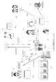
- FIG. 1 is a block diagram showing a schematic configuration of a watching information sharing system according to an embodiment.
- the external view which shows an example of a 1st information terminal.
- the block diagram which shows an example of an internal structure of a thin module component.
- the block diagram which shows an example of an internal structure of ASIC.
- the block diagram of the modification of a 2nd information terminal The block diagram which shows an example of an internal structure of an information display apparatus.
- the sequence diagram which shows an example of the registration procedure of a person to watch over The sequence diagram following FIG. 9A.
- the sequence diagram which shows an example of the information reading process of the 1st information terminal by a 2nd information terminal.
- the sequence diagram which shows an example of the decoding process of the 1st encoding information by a 3rd information terminal.
- FIG. 1 is a block diagram illustrating a schematic configuration of a watching information sharing system 1 according to an embodiment of the present disclosure.
- the watching information sharing system 1 of FIG. 1 includes a first information terminal 3 possessed by the watching target person 2, a second information terminal 5 operated by the first visiting person 4 meeting the watching target person 2, and an output device 6. It has.
- the meeting place is not particularly limited, but is, for example, the home of the person 2 to be watched over.
- home refers to the current residence of the person to be watched 2, and when the person to be watched 2 currently lives in a place other than the home of the person to be watched 2. Is intended to include the place where you currently live.
- the first visitor 4 is, for example, a person dispatched from a business operator who provides a watching service. Therefore, the first visitor 4 is not necessarily the same person.
- the first visitor 4 carries the second information terminal 5 and regularly visits a meeting place such as a home of the person 2 to be watched over to visit.
- the first visitor 4 visits the meeting place with the watching target person 2 by watching the second information terminal 5 at the meeting place such as the home of the target person 2, the first visiting person 4 2
- the information terminal 5 may be operated.
- the 1st visitor 4 does not necessarily carry the 2nd information terminal 5 at the time of visit of the monitoring subject 2.
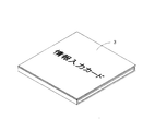
- FIG. 2 is an external view showing an example of the first information terminal 3 possessed by the person 2 to be watched over.
- the first information terminal 3 in FIG. 2 is a sheet-like information input card 3 made of paper or resin.
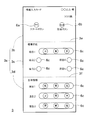
- This information input card 3 is a foldable type, and when unfolded, an information input surface 3a as shown in FIG. 3 appears.
- the information input surface 3a is provided with a plurality of selection buttons (first input units) 6a, 6b, and 6c that the watching target person 2 presses with their fingers.
- the first information terminal 3 in FIG. 2 is provided by, for example, a business operator who provides a watching service.
- the first visitor 4 who regularly meets the watching target person 2 may watch over the first information terminal 3 and hand it to the receiving person 2 at the first meeting.
- the first information terminal 3 may be sent from the above company to the watching target person 2 by mail or the like.
- the first information terminal 3 is used for the person to be watched 2 to mainly input information related to the health condition.
- the first information terminal 3 stores a plurality of selection buttons 6a, 6b, 6c, a function for storing information input by pressing these selection buttons, and outputs the stored information to the outside. Interface function.
- the first information terminal 3 in FIG. 2 is driven by a battery, and is assumed to be discarded when the battery runs out. That is, since the first information terminal 3 is assumed to be disposable, the first information terminal 3 is made of an inexpensive sheet member such as paper or resin in order to suppress the member cost as much as possible.
- the battery of the first information terminal 3 may be replaceable so that it can be used for a long time. In this case, the first information terminal 3 is desirably formed of a resin having excellent durability.
- the information input surface 3a has a three-surface configuration including a first input surface 3b, a second input surface 3c, and a third input surface 3d, and folds 3e and 3f are formed at the boundaries between the surfaces. It can be folded at these folds 3e and 3f.
- FIG. 2 shows a state where the information input surface 3a is folded at the creases 3e and 3f.
- a start button 6a and a cancel button 6b are provided on the first input surface 3b.
- a selection button 6c for inputting a basic health state of the person to be watched over 2 is provided on the second input surface 3c.
- the third input surface 3d is provided with a selection button 6c for inputting information related to some biological information.
- the information input on the information input screen is not limited to that shown in FIG.
- information regarding the disease may be input.
- the information input card 3 in FIG. 1 is manufactured by folding a sheet material made of paper, resin, or the like. By folding the sheet material, the information input surface 3a described above appears on the surface, and a circuit pattern surface (not shown) is provided on the back side. On the circuit pattern surface, a conductive pattern connected to the contact point of each selection button 6c is formed, and a thin module component is mounted.
- FIG. 4 is a block diagram showing an example of the internal configuration of the thin module component 10.
- the thin module component 10 of FIG. 4 includes a thin film substrate 11 thinner than the paper thickness, an ASIC (Application Specific Integrated Circuit) 12 mounted thereon, a crystal resonator 13, a button cell 14, and a speaker. 15, a plurality of terminals 16 formed along the long side of the film substrate 11, and an antenna pattern 17 formed along the outer edge of the film substrate 11.
- ASIC Application Specific Integrated Circuit
- FIG. 4 shows a block configuration in which the internal configuration of the thin module component 10 is functionalized, and the actual arrangement, size, shape, and number of circuit components and patterns can be arbitrarily changed.
- FIG. 5A is a block diagram showing an example of the internal configuration of the ASIC 12.
- the ASIC 12 in FIG. 5 includes a first information storage unit 21 that stores information on the start button 6a, the cancel button 6b, and each selection button 6c pressed by the person to be watched 2 together with time information (time stamp information) in time series,
- the control part 22 which performs control which memorize
- the control unit 22 When the function of the control unit 22 is low, the information once stored in the first information storage unit 21 may not be erased or overwritten. Therefore, when the cancel button 6b is pressed, the control unit 22 does not delete the information stored in the first information storage unit 21 immediately before, but additionally stores information indicating that the information is incorrect. May be. Thereby, when information is read by the information management device 9 managed by a service provider or the like while watching the information on the information input card 3, it can be easily and accurately determined whether or not the information is correct for each stored information.
- the control unit 22 when the function of the control unit 22 is high, the information once stored in the first information storage unit 21 may be erased or overwritten. Therefore, when the cancel button 6b is pressed, the control unit 22 directly deletes the information stored in the first information storage unit 21 immediately before that. Therefore, it is not necessary to continue storing wrong information in the first information storage unit 21, the storage capacity in the first information storage unit 21 can be effectively used, and whether the information read out on the information management device 9 side is correct. It is not necessary to determine whether or not, and the reading process can be speeded up.
- cancel button 6b By providing such a cancel button 6b, it is possible to cancel the information of the selection button 6c that was pressed immediately before, and the person to be watched over 2 can repeat the button operation as many times as possible. You are freed from the mental burden of not being allowed.
- the information input card 3 may incorporate a communication function so that the information stored in the first information storage unit 21 can be transmitted to an external device without contact, for example.
- a wireless communication unit (not shown) may be provided inside the ASIC 12.
- the wireless communication unit performs non-contact communication such as so-called NFC (Near Field Communication) or Bluetooth (registered trademark) with the information management device 9 and transmits / receives information via the interface unit 23.
- NFC Near Field Communication
- Bluetooth registered trademark
- the method and frequency band used by the wireless communication unit for wireless communication are not particularly limited. For example, in the case of NFC, wireless communication is performed using a wireless method compliant with ISO14443 in the 13.56 MHz band, and in the case of Bluetooth, the standard is defined.
- Wireless communication is performed at a frequency (for example, 2.4 GHz).
- Various types of information stored in the first information storage unit 21 described above are transmitted to the information management device 9 via the wireless communication unit.
- how the state of the watching target person 2 has changed over a predetermined period of time can be finely managed on the information management device 9 side by side in a time-series manner, and the monitoring target person 2 suffering from a specific disease can be managed.
- the information input card 3 As long as the button battery 14 is mounted, the battery will run out when used for a long period of time, but the information input card 3 according to the present embodiment employs a sheet material to provide some durability and waterproofness, Since a structure in which the battery can be replaced is not employed, the structure is simplified on the assumption that the information input card 3 itself is replaced when the battery runs out.
- the storage capacity of the first information storage unit 21 is limited, if there is no capacity to store the information of the selection button 6c newly pressed by the watching target person 2, a warning sound is generated and 1 Watching that the storage capacity of the information storage unit 21 is full may be notified to the subject person 2. In this case, as described later, a function of erasing all information stored in the first information storage unit 21 may be provided. However, the first visitor 4 performs a special operation so that the information stored in the first information storage unit 21 can be erased so that the target person 2 does not mistakenly use this function. Good.
- the ASIC 12 in FIG. 5A shows an example in which the button operation information of the start button 6a, the cancel button 6b, and the selection buttons 6c pressed by the person to be watched 2 is stored in the first information storage unit 21 without being encoded. Since the button operation information of the person to be watched over 2 is personal information, the button operation information may be encoded and stored in the first information storage unit 21 for personal information protection.
- the internal configuration of the ASIC 12 in this case is represented by a block diagram as shown in FIG. 5B.
- the ASIC 12 in FIG. 5B includes a first encoding unit 24 in addition to the configuration in FIG. 5A.
- the 1st encoding part 24 produces
- the 1st information storage part 21 of Drawing 5B memorizes the 1st coding information.
- the first encoded information stored in the first information storage unit 21 is read by the second information terminal 5 as will be described later. Even if a malicious person reads the first encoded information, since it is encoded, the button operation information is not grasped as it is. Thereby, it is possible to protect personal information of the person being watched over.
- FIG. 6A is a block diagram showing an example of the internal configuration of the second information terminal 5 operated by the first visitor 4.
- the second information terminal 5 shown in FIG. 6A corresponds to the first information terminal 3 including the ASIC 12 shown in FIG. 5A.
- the second information terminal 5 is, for example, a tablet terminal or a laptop PC.
- the second information terminal 5 may be a stationary PC.
- the second information terminal 5 in FIG. 6A includes an information reading unit 31 that reads information stored in the first information storage unit 21 in the first information terminal 3, a second information storage unit 32 that stores the read information, A first encoding unit 33 that generates first encoded information 7a obtained by encoding the read information, a first output control unit 34 that causes the output device 6 to output the first encoded information 7a, and a display unit 35.
- an information reading unit 31 that reads information stored in the first information storage unit 21 in the first information terminal 3
- a second information storage unit 32 that stores the read information
- a first encoding unit 33 that generates first encoded information 7a obtained by encoding the read information
- a first output control unit 34 that causes the output device 6 to output the first encoded information 7a
- a display unit 35 a display unit 35.
- the information reading unit 31 reads information from the first information storage unit 21 in the first information terminal 3 using a wireless line such as NFC, for example.
- the encoded information generated by the first encoding unit 33 is a QR code, a barcode, or the like.
- the reason for generating the encoded information is that the information stored in the first information storage unit 21 in the first information terminal 3 is the personal information of the person 2 to be watched over, so that this information cannot be grasped at a glance. This is to protect personal information.
- encoding may be performed by a secure method such as key information.
- the output device 6 in the present embodiment is, for example, a printer (printing device).
- the first output control unit 34 in the second information terminal 5 prints the first encoded information 7a on a print medium such as a paper medium by, for example, a printer.
- the first visitor 4 prints the first encoded information 7a on the paper medium at the visit to the watching target person 2.
- the first visitor 4 affixes the printed first encoded information 7a to, for example, a notebook for recording watching information that has been conventionally used. Thereby, the 1st visitor 4 does not need to hand-watch watch information on a notebook at the time of the visit of the watch target person 2, and the burden of the 1st visitor 4 is reduced.
- the second information terminal 5 is installed with application software (hereinafter referred to as a first application) for performing each processing operation of the information reading unit 31, the first encoding unit 33, and the first output control unit 34.
- a first application application software
- the first visitor 4 executes the first application on the second information terminal 5
- the information is read from the first information terminal 3, stored in the second information storage unit 32, and the information is encoded.
- a series of processes to be output to the output device 6 can be performed.
- the 2nd information terminal 5 may be provided with the 2nd input part 36 which inputs the impression etc. which the 1st visitor 4 grasped
- the first encoding unit 33 in the second information terminal 5 encodes the information read by the information reading unit 31 and the information input by the second input unit 36, and the first encoded information 7a. May be generated.
- the first encoded information 7a includes not only the information input by the watching target person 2 but also the information acquired by the first visiting person 4 meeting the watching target person 2, Use value of information becomes high.
- the first encoded information 7a is realized by a QR code (registered trademark) or a barcode
- the amount of data that can be stored is limited, and thus the information obtained by the first visitor 4 meeting the person 2 to be watched and acquired It may not be included.
- a separate QR code or bar code may be provided. That is, the number of the first encoded information 7a printed on the paper medium may be arbitrarily changed according to the amount of data to be printed.
- the first encoded information 7a based on the information read by the information reading unit 31 and the first encoded information 7a based on the information input by the second input unit 36 can be distinguished from each other. You may print on a paper medium with a different display form. For example, the color of one first encoded information 7a and the other first encoded information 7a may be changed. Thereby, when decoding the first encoded information 7a later, it is possible to decode only the information input by the watching target person 2 or decode only the information input by the first visitor 4.
- the output device 6 in the present embodiment is not limited to a printer, and may be, for example, an information display device.
- the information display device is a PC, a tablet terminal, a smartphone, a monitor terminal, or the like placed in a meeting place such as a home of the person 2 to be watched over.
- FIG. 7 is a block diagram showing an example of the internal configuration of the information display device 37. 7 includes a third storage unit 38 that stores the first encoded information 7a, and a display unit (first display unit) that displays the first encoded information 7a stored in the third storage unit 38. 39).
- the first encoded information 7 a printed on a paper medium or displayed on the information display device 37 may be acquired by a specific third party other than the person to be watched 2 and the first visitor 4.
- a specific third party is a person who needs to watch over the person 2 to be watched.
- a close relative such as the family of the person 2 to be watched over or some medical action on the person 2 to be watched over Medical personnel who perform medical care.
- the close relative includes the legal representative of the person 2 who is not watched. Or the person requested by the watching target person 2 or his family is also included. Medical personnel include primary doctors, pharmacists, and nutrition managers.
- such specific third parties are collectively referred to as a second visitor 7.
- the provision of the first encoded information 7a to the second visitor 7 is performed by the third information terminal 40.
- the third information terminal 40 is, for example, a tablet terminal or a laptop PC held by the second visitor 7.
- the second visitor 7 carries the third information terminal 40 and visits a visit place such as the home of the person 2 to be watched over to visit.
- the third information terminal 40 may be placed at a meeting place such as the home of the person 2 to be watched over.
- the second visitor 7 operates the third information terminal 40 when meeting the watching target person 2.
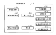
- the second information terminal 5 may include a time adjustment unit 51 and an initialization unit 52 as shown in FIG.
- the time adjustment unit 51 periodically adjusts the time. Since the first information terminal 3 possessed by the person to be watched 2 receives time information from the second information terminal 5, if the time of the second information terminal 5 is incorrect, the time of the first information terminal 3 is also incorrect. Become. Therefore, it is desirable to provide the time adjustment unit 51 in the second information terminal 5.
- the initialization unit 52 initializes the first information terminal 3 to be handed over to the new watching target person and transmits the time to the first information terminal 3. By providing the initialization unit 52, the second information terminal 5 can initialize the first information terminal 3.
- the second information terminal 5 may include a confirmation item information generation unit 53, a confirmation item information transmission unit 54, and a management information generation unit 55.
- the confirmation item information generation unit 53 is specific to each person to be watched, and generates confirmation item information input by the person to be watched by the first information terminal 3. Details of the confirmation item information will be described later.
- the confirmation item information transmission unit 54 transmits confirmation item information when the first information terminal 3 passed to the watching target person 2 is initialized.
- the management information generation unit 55 includes first identification information for identifying the person being watched over, second identification information for identifying the first information terminal 3 passed to the person being watched over, and confirmation item information unique to the person being watched over. Generate linked management information.
- FIG. 6B is a block diagram showing an internal configuration of the second information terminal 5 corresponding to the first information terminal 3 incorporating the ASIC 12 of FIG. 5B.
- the second information terminal 5 in FIG. 6B is obtained by omitting the first encoding unit 33 from FIG. 6A.
- the information reading unit 31 in the second information terminal 5 in FIG. 6B reads the first encoded information stored in the first information storage unit 21 in the ASIC 12.
- the second information storage unit 32 stores the first encoded information read by the information reading unit 31.
- FIG. 8 is a block diagram showing an example of the internal configuration of the third information terminal 40.
- the third information terminal 40 in FIG. 8 includes an information reading unit 41 that reads the first encoded information 7a output to the output device 6, and a decoding unit that decodes the read first encoded information 7a into information before encoding. 42 and a display unit (second display unit) 43 for displaying the decoded information.
- the information reading unit 41 has, for example, a camera built in the third information terminal 40.
- the first encoded information 7a is photographed by this camera.
- the decoding unit 42 analyzes the captured image of the camera and decodes the first encoded information 7a into information before encoding.
- the second visitor 7 confirms the information input to the first information terminal 3 by the watching target person 2 based on the decrypted information displayed on the display unit 43 of the third information terminal 40. If there is information input to the second information terminal 5 by the first visitor 4, this information is also confirmed on the display unit 43.
- the second visitor 7 visits the watching target person 2 while referring to the information confirmed on the display unit 43, and performs treatment, diagnosis, examination, medical inquiry, medicine dispensing, etc. as necessary. For example, if the second visitor 7 is an attending physician, based on the information confirmed on the display unit 43, the treatment method is changed, a new examination, or a medicine prescription is made. If the second visitor 7 is a pharmacist, the medicine is dispensed based on the information confirmed on the display unit 43.
- the same information reading unit 41 and decoding unit 42 as the third information terminal 40 may be provided in the second information terminal 5 operated by the first visitor 4. Accordingly, the first visitor 4 can also read and decode the first encoded information 7 a using the second information terminal 5, and check the decoded information on the display unit 43.
- application software (hereinafter referred to as a second application) for performing each processing operation of the information reading unit 41 and the decoding unit 42 is installed.
- a second application application software for performing each processing operation of the information reading unit 41 and the decoding unit 42 is installed.
- the second visitor 7 executes the second application on the third information terminal 40, a series of processes of reading information from the output device 6, decoding it, and displaying it on the display unit 43 can be performed.
- the third information terminal 40 includes a third input unit 44 for inputting an impression and the like that the second visitor 7 has grasped by exchanging conversations with the watching target person 2, and information input by the third input unit 44.
- the 3rd information terminal 40 can output the 2nd coding information which coded the information which the 2nd meeting person 7 met and acquired the person 2 to watch over to the output device 6. Therefore, the first visitor 4 and the other second visitor 7 can grasp what impression the second visitor 7 had on the watching target person 2 by decoding this information. For example, if the second visitor 7 is an attending physician, if it is determined that the health status of the person 2 to be watched is good, information indicating that the visit interval of the first visitor 4 may be increased, or a pharmacist Second encoded information including information instructing a change in the type and amount of medicine to be dispensed may be generated.
- the third information terminal 40 accesses the information management apparatus 9 that centrally manages the information input to the first information terminal 3 by the person being watched over 2 through a wired or wireless line, and is managed by the information management apparatus 9. It may be possible to refer to information to be performed.
- a communication control unit 47 is provided in the third information terminal 40.
- the first visitor 4 is a person dispatched from a business operator who provides a watching service.
- This provider includes an information management device 9 that manages the person 2 to be watched over.
- This information management device 9 can be realized by a server or a PC.
- the information management device 9 manages the name and identification information of each person to be watched 2 in association with the information acquired from the first information terminal 3 by the second information terminal 5.
- the information management device 9 can send and receive information to and from the second information terminal 5 in a wired or wireless manner. Further, the information management device 9 may be able to send and receive information to and from the third information terminal 40 by wire or wireless.
- step S1 the information management device 9 managed by the monitoring service provider activates dedicated application software (hereinafter, third application) (step S1).
- step S2 the operator of the information management device 9 inputs a predetermined user ID and password (step S2).
- the operator in this case is, for example, the first visitor 4 who is scheduled to meet regularly with the new watching target person 2. Alternatively, another person who receives a request from the first visitor 4 may be used.
- step S3 the operator selects a new registration of the watching target person.
- step S4 a watching target person ID (first identification information) for identifying the watching target person is selected (step S4).
- step S5 the operator registers personal information such as the name and address of the person being watched over.
- step S6 The operator confirms that there is no error in the state registered in the information management device 9 (step S6).
- the operator adjusts the time of the second information terminal 5 (step S11).
- the time information of the second information terminal 5 is transmitted to the first information terminal 3, if the time of the second information terminal 5 is incorrect, the time of the first information terminal 3 is also incorrect. turn into. For this reason, it is necessary to periodically adjust the time of the second information terminal 5.
- the specific process which adjusts the time of the 2nd information terminal 5 does not ask
- the time may be adjusted by accessing a specific site from the second information terminal 5, or the time may be adjusted via a telephone line or the like.
- the operator may be able to adjust the time of the second information terminal 5 manually.
- step S12 the operator activates dedicated application software (hereinafter, fourth application) on the second information terminal 5 (step S12).
- fourth application the operator inputs a user ID and a password (step S13).
- the operator instructs initial registration of the first information terminal 3 on the second information terminal 5 (step S14).
- the operator instructs acquisition of the watching target person ID of the newly registered watching target person (step S15). Further, the operator instructs the information management apparatus 9 to link the registered information with the second information terminal 5 (step S7). In response to this instruction, the information management device 9 transmits newly registered registration information of the watching target person 2 to the second information terminal 5 (step S8).
- the registration information may be transmitted by wire or wireless. Wired transmission is, for example, communication via a USB (Universal Serial Bus) terminal or Ethernet (registered trademark).
- the wireless transmission is, for example, communication via WiFi (registered trademark), wireless LAN (Local Area Network), or the like.
- the second information terminal 5 receives the registration information transmitted from the information management device 9 and stores it in a predetermined storage unit in the second information terminal 5 (step S16).
- the storage unit may be the second information storage unit 32 of FIG. 6 or a storage unit provided separately from the second information storage unit 32.
- the operator registers confirmation item information unique to the new watching target person using the second information terminal 5 (step S17).
- the confirmation item information is information input by the specific watching target person 2 at the first information terminal 3, for example, information on the disease or health condition of the specific watching target person 2. As a more specific example, if it is the watching target person 2 with high blood pressure, information regarding blood pressure may be used as the confirmation item information.
- the process of step S17 is arbitrary. If the confirmation item information is not necessary, the process of step S17 may be omitted.
- the operator instructs the initialization of the first information terminal 3 with the first information terminal 3 scheduled to be distributed to the new watching target person 2 (step S18 in FIG. 9B). .
- This instruction is given by the second information terminal 5.
- the initialization information is transmitted from the second information terminal 5 to the first information terminal 3, for example, wirelessly (step S19).
- the initialization information includes, for example, time information and confirmation item information.
- the first information terminal 3 receives the initialization information transmitted from the second information terminal 5 (step S31), corrects the time in the first information terminal 3 (step S32), and initializes the first information terminal 3 (Step S33). Also, confirmation item information is set in the first information terminal 3 (step S34).
- the information input card 3 in FIG. 3 has items 1 to 3 as health conditions and items 1 to 3 as biometric information. At least some of these items 1 to 3 may be capable of arbitrarily changing the specific contents of the items according to the confirmation item information transmitted from the second information terminal 5. In this case, it is necessary to set what kind of contents each item is in the information input card 3. This process is performed in step S34.
- the first information terminal 3 When the process of step S34 is completed, the first information terminal 3 notifies the second information terminal 5 by radio that the initialization is completed (step S35). At this time, the first information terminal 3 transmits a terminal ID for identifying the first information terminal 3 and a time (time stamp) managed by the first information terminal 3 to the second information terminal 5.
- the second information terminal 5 Upon receiving this notification, the second information terminal 5 generates management information (step S20).
- the management information is set to the watching target person ID (first identification information), the terminal ID (second identification information) of the first information terminal 3 possessed by the watching target person, and the first information terminal 3. This information is associated with the confirmation item information.
- the second information terminal 5 transmits the management information to the information management device 9 by wire or wireless (step S21).
- the information management device 9 watches the received management information and registers it in the target person DB (step S9), and ends the third application (step S10).
- the second information terminal 5 ends the fourth application after transmitting the management information to the information management device 9 (step S22).
- FIG. 10 is a sequence diagram illustrating an example of information reading processing of the first information terminal 3 by the second information terminal 5.
- FIG. 10 shows an example in which a printer is used as the output device 6.
- the first visitor 4 activates the first application on the second information terminal 5 (step S41).
- the first visitor 4 also starts the printer as the output device 6 before and after step S41 (step S42).
- the first visitor 4 When the login screen is displayed on the second information terminal 5, the first visitor 4 inputs a predetermined user ID and password (step S43).
- the menu screen When the menu screen is displayed, the first visitor 4 selects data reading from the menu (step S44).
- the 2nd information terminal 5 transmits an information transmission request to the 1st information terminal 3 by a wireless line, for example (Step S45).
- the first information terminal 3 that has received this request transmits the information stored in the first information storage unit 21 to the second information terminal 5 via a wireless line (step S46).
- the second information terminal 5 receives the information from the first information terminal 3 (step S47), and stores the received information in the second information storage unit 32 (step S48).
- the first encoding unit 33 generates first encoded information 7a obtained by encoding the received information (step S49).
- the first output control unit 34 instructs the printer to print the first encoded information 7a (step S50), and thereafter ends the first application (step S51).
- the printer prints the first encoded information 7a on a paper medium (step S52), and then turns off the printer (step S53).
- the first visitor 4 attaches a paper medium on which the first encoded information 7 a is printed, for example, to the notebook 7. Instead of pasting on the note 7, the paper medium may be directly filed. Further, attached information such as time information (time stamp information) may be appended to the first encoded information 7a printed on the paper medium. Since the attached information is not personal information, it is not necessarily encoded. 10 shows an example in which encoding is performed by the second information terminal 5, but the first information terminal 3 having the ASIC 12 of FIG. 5B and the second information terminal 5 of FIG. 6B are provided. Since the first information terminal 3 performs encoding, the second information terminal 5 can omit the encoding process.
- FIG. 11 is a sequence diagram illustrating an example of information erasing processing in the first information storage unit 21.
- the information in the first information storage unit 21 is transferred to the second information terminal 5.
- data erasure is selected from the menu screen of the second information terminal 5 (step S61).
- a data erasure request is transmitted from the second information terminal 5 to the first information terminal 3 via a wireless line (step S62).
- the first information terminal 3 erases all the information in the first information storage unit 21 (step S63), and transmits information indicating that the erasure is completed to the second information terminal 5 via a wireless line. (Step S64).
- information indicating that the erasure is completed is displayed on the display unit 35 of the second information terminal 5 (step S65).
- the second information terminal 5 or the third information terminal 40 can decode the first encoded information 7a.
- FIG. 12 is a sequence diagram showing an example of the decoding process of the first encoded information 7a by the third information terminal 40.
- 2nd visitor 8 starts the 2nd application in the 3rd information terminal 40 (Step S71), and will input a user ID and a password, if a login screen is displayed (Step S72).
- a login screen is displayed
- reading of encoded information is selected from the menu screen (step S73).
- the camera corresponding to the information reading unit 41 in the third information terminal 40 captures the first encoded information 7a (step S74).
- the decoding unit 42 in the third information terminal 40 analyzes the captured image and decodes the first encoded information 7a (Step S75).
- the third information terminal 40 displays the decoded information on the display unit 43 (step S76).
- the second application is terminated after saving the decrypted information as necessary (step S77).
- FIG. 13 is a sequence diagram showing an example of a process for centrally managing information in the second information terminal 5 by the information management apparatus 9.
- 1st visitor 4 starts the 1st information terminal 3 (step S81), and connects the 1st information terminal 3 and the information management apparatus 9 (step S82). This connection may be wired or wireless.
- a predetermined administrator starts dedicated application software on the first information management apparatus 9 (step S83), and inputs a login ID and password (step S84). ), Information reading of the watching target person 2 is selected from the menu screen (step S85).
- step S86 specify the import file and save destination.
- step S87 an information read request is transmitted to the second information terminal 5 (step S87).
- the second information terminal 5 transmits the information of the watching target person 2 read from the first information terminal 3 to the information management device 9 (step S88).
- the information management device 9 stores the received information in the specified import file and transfers it to the storage destination specified in step S86 (step S89).
- step S90 the storage completion is displayed on the display unit of the information management device 9 (step S90), the application is terminated (step S91), and the power of the second information terminal 5 is turned off (step S92). .
- the button operation information input by the watching target person 2 at the first information terminal 3 is encoded at the first information terminal 3 or the second information terminal 5 and output to the output device 6. Even in a situation where the network environment is not maintained, the information stored in the first information terminal 3 can be used effectively. Further, the information output by the output device 6 is information encoded in the first information terminal 3 and is information necessary for watching the watching target person 2 while protecting the personal information of the watching target person 2. Can be shared.
- the second visitor 8 can decode the first encoded information 7a output from the output device 6 by a simple procedure, the second visitor 8 can provide various services to the watching target person 2 while checking the decoded information. .
- the first visitor 4 and the second visitor 8 can also encode the new information acquired by the visit with the watching target person 2 and output it to the output device 6, and watch over the watching target person 2. It is possible to accumulate information necessary for
- At least a part of the watching information sharing system 1 described in the above-described embodiment may be configured with hardware or software.
- a program that realizes at least a part of the functions of the watching information sharing system 1 may be stored in a recording medium such as a flexible disk or a CD-ROM, and read and executed by a computer.
- the recording medium is not limited to a removable medium such as a magnetic disk or an optical disk, but may be a fixed recording medium such as a hard disk device or a memory.
- a program that realizes at least a part of the functions of the watching information sharing system 1 may be distributed via a communication line (including wireless communication) such as the Internet. Further, the program may be distributed in a state where the program is encrypted, modulated or compressed, and stored in a recording medium via a wired line such as the Internet or a wireless line.
Landscapes
- Business, Economics & Management (AREA)
- Emergency Management (AREA)
- Physics & Mathematics (AREA)
- General Physics & Mathematics (AREA)
- Alarm Systems (AREA)
- Telephonic Communication Services (AREA)
Abstract
見守り対象者の個人情報を保護しつつ、見守り対象者の見守り情報を有効利用する。見守り対象者が所持する第1情報端末と、見守り対象者に面会する第1面会者が操作する第2情報端末と、出力装置と、を備えた見守り情報共有システムの第1情報端末は、見守り対象者が情報を入力する第1入力部と、第1入力部にて入力された情報を記憶する第1情報記憶部と、を有する。第2情報端末は、第1情報記憶部に記憶された情報を読み出す情報読出部と、情報読出部にて読み出された情報を記憶する第2情報記憶部と、情報読出部にて読み出された情報を符号化した第1符号化情報を生成する第1符号化部と、第1符号化情報を出力装置に出力させる第1出力制御部と、を有する。
Description
本開示は、見守り対象者の見守り情報を共有する見守り情報共有システムに関する。
高齢者や要介護者の数の増加に伴って、医療費が急増している。医療費を削減するには、医療施設や介護施設の入居者をできるだけ減らす必要がある。このような背景から、高齢者や要介護者の自宅を定期的に訪問して面会する見守りサービスが注目されている。
例えば、特開2014-186402号公報には、高齢者等の見守り対象者の生体情報と生活行動状況とをネットワーク経由で管理装置に送信し、管理装置は受信した生体情報と生活行動状況に基づいて見守り対象者の健康状態を判定している。
しかしながら、上記特開2014-186402号公報のシステムを構築するには、見守り対象者の自宅に生体情報計測装置や生活行動取得装置、センサなどを設置するとともに、これら装置で計測または取得した情報を管理装置に送信するネットワーク環境を設けなければならず、かなりの設備コストがかかってしまう。見守り対象者の自宅に事前に備わっているネットワーク環境を流用できる場合もあるが、すべての見守り対象者がネットワーク環境を所持しているとは限らない。
また、見守り対象者を見守るべき人間は、見守りサービスを行う事業者だけでなく、医師や薬剤師等の医療関係者や見守り対象者の家族など、多岐にわたっており、管理装置が管理する情報を利用しやすくする必要がある。その一方で、見守り対象者の個人情報を保護する対策も必要となる。
本開示は、上述した課題に鑑みてなされたものであり、その目的は、設備コストをかけることなく、また、見守り対象者の個人情報を保護しつつ、見守り対象者の見守り情報を有効利用できるようにした見守り情報共有システムを提供することにある。
上記の課題を解決するために、本開示の一態様では、見守り対象者が所持する第1情報端末と、前記見守り対象者に面会する第1面会者が操作する第2情報端末と、出力装置と、を備えた見守り情報共有システムであって、
前記第1情報端末は、
見守り対象者が情報を入力する第1入力部と、
前記第1入力部にて入力された情報を記憶する第1情報記憶部と、を有し、
前記第2情報端末は、
前記第1情報記憶部に記憶された情報を読み出す情報読出部と、
前記情報読出部にて読み出された情報を記憶する第2情報記憶部と、
前記情報読出部にて読み出された情報を符号化した第1符号化情報を生成する第1符号化部と、
前記第1符号化情報を前記出力装置に出力させる第1出力制御部と、を有する、見守り情報共有システムが提供される。
前記第1情報端末は、
見守り対象者が情報を入力する第1入力部と、
前記第1入力部にて入力された情報を記憶する第1情報記憶部と、を有し、
前記第2情報端末は、
前記第1情報記憶部に記憶された情報を読み出す情報読出部と、
前記情報読出部にて読み出された情報を記憶する第2情報記憶部と、
前記情報読出部にて読み出された情報を符号化した第1符号化情報を生成する第1符号化部と、
前記第1符号化情報を前記出力装置に出力させる第1出力制御部と、を有する、見守り情報共有システムが提供される。
本開示の他の一態様では、見守り対象者が所持する第1情報端末と、前記見守り対象者に面会する第1面会者が操作する第2情報端末と、出力装置と、を備えた見守り情報共有システムであって、
前記第1情報端末は、
見守り対象者が情報を入力する第1入力部と、
前記第1入力部にて入力された情報を符号化した第1符号化情報を生成する第1符号化部と、
前記第1符号化情報を記憶する第1情報記憶部と、を有し、
前記第2情報端末は、
前記第1情報記憶部に記憶された前記第1符号化情報を読み出す情報読出部と、
前記情報読出部にて読み出された前記第1符号化情報を記憶する第2情報記憶部と、
前記第1符号化情報を前記出力装置に出力させる第1出力制御部と、を有する、見守り情報共有システムが提供される。
前記第1情報端末は、
見守り対象者が情報を入力する第1入力部と、
前記第1入力部にて入力された情報を符号化した第1符号化情報を生成する第1符号化部と、
前記第1符号化情報を記憶する第1情報記憶部と、を有し、
前記第2情報端末は、
前記第1情報記憶部に記憶された前記第1符号化情報を読み出す情報読出部と、
前記情報読出部にて読み出された前記第1符号化情報を記憶する第2情報記憶部と、
前記第1符号化情報を前記出力装置に出力させる第1出力制御部と、を有する、見守り情報共有システムが提供される。
前記第2情報端末は、
前記見守り対象者に面会した前記第1面会者が情報を入力する第2入力部を有してもよく、
前記第1符号化部は、前記情報読出部にて読み出された情報と、前記第2入力部にて入力された情報と、を符号化した前記第1符号化情報を生成してもよい。
前記見守り対象者に面会した前記第1面会者が情報を入力する第2入力部を有してもよく、
前記第1符号化部は、前記情報読出部にて読み出された情報と、前記第2入力部にて入力された情報と、を符号化した前記第1符号化情報を生成してもよい。
前記出力装置は、印刷装置であってもよく、
前記第1面会者は、前記見守り対象者に面会時に、前記第1符号化情報を前記印刷装置で印刷した印刷媒体を作製してもよい。
前記第1面会者は、前記見守り対象者に面会時に、前記第1符号化情報を前記印刷装置で印刷した印刷媒体を作製してもよい。
前記出力装置は、情報表示装置であってもよく、
前記情報表示装置は、
前記第1符号化情報を記憶する第3記憶部と、
前記第3記憶部に記憶された前記第1符号化情報を表示する第1表示部と、を有してもよい。
前記情報表示装置は、
前記第1符号化情報を記憶する第3記憶部と、
前記第3記憶部に記憶された前記第1符号化情報を表示する第1表示部と、を有してもよい。
前記見守り対象者に面会する第2面会者が操作する第3情報端末を備えてもよく、
前記第3情報端末は、
前記出力装置に出力された前記第1符号化情報を読み取る情報読取部と、
前記情報読取部で読み取った前記第1符号化情報を符号化前の情報に復号する復号部と、
前記復号された情報を表示する第2表示部と、を有してもよい。
前記第3情報端末は、
前記出力装置に出力された前記第1符号化情報を読み取る情報読取部と、
前記情報読取部で読み取った前記第1符号化情報を符号化前の情報に復号する復号部と、
前記復号された情報を表示する第2表示部と、を有してもよい。
前記第3情報端末は、
前記見守り対象者に面会した前記第2面会者が情報を入力する第3入力部と、
前記第3入力部にて入力された情報を符号化した第2符号化情報を生成する第2符号化部と、
前記第2符号化情報を前記出力装置に出力させる第2出力制御部と、を有してもよい。
前記見守り対象者に面会した前記第2面会者が情報を入力する第3入力部と、
前記第3入力部にて入力された情報を符号化した第2符号化情報を生成する第2符号化部と、
前記第2符号化情報を前記出力装置に出力させる第2出力制御部と、を有してもよい。
前記第2情報記憶部に記憶された情報を管理する情報管理装置を備えてもよく、
前記第3情報端末は、有線または無線の回線を介して、前記情報管理装置が管理する情報にアクセスする通信制御部を有してもよい。
前記第3情報端末は、有線または無線の回線を介して、前記情報管理装置が管理する情報にアクセスする通信制御部を有してもよい。
前記第2情報端末は、定期的に前記見守り対象者に面会して前記第1情報記憶部に記憶された情報を収集するサービスを行うサービス事業者により所持され、
前記第3情報端末は、前記見守り対象者の治療および薬の調剤の少なくとも一方を行う医療関係者と、前記見守り対象者の近親者と、の少なくとも一方により所持されてもよい。
前記第3情報端末は、前記見守り対象者の治療および薬の調剤の少なくとも一方を行う医療関係者と、前記見守り対象者の近親者と、の少なくとも一方により所持されてもよい。
前記第2情報端末は、
定期的に時刻を合わせる時刻調整部と、
新規の見守り対象者に渡される前記第1情報端末の初期化を行うとともに、前記第1情報端末に前記時刻を送信する初期化部と、を有していてもよい。
定期的に時刻を合わせる時刻調整部と、
新規の見守り対象者に渡される前記第1情報端末の初期化を行うとともに、前記第1情報端末に前記時刻を送信する初期化部と、を有していてもよい。
前記第2情報端末は、
個々の見守り対象者に固有で、前記第1情報端末にて前記見守り対象者が入力する確認項目情報を生成する確認項目情報生成部と、
前記見守り対象者に渡される前記第1情報端末の初期化時に前記確認項目情報を送信する確認項目情報送信部と、
前記見守り対象者を識別する第1識別情報と、前記見守り対象者に渡される前記第1情報端末を識別する第2識別情報と、前記見守り対象者に固有の前記確認項目情報とを紐付けた管理情報を生成する管理情報生成部と、を有していてもよい。
個々の見守り対象者に固有で、前記第1情報端末にて前記見守り対象者が入力する確認項目情報を生成する確認項目情報生成部と、
前記見守り対象者に渡される前記第1情報端末の初期化時に前記確認項目情報を送信する確認項目情報送信部と、
前記見守り対象者を識別する第1識別情報と、前記見守り対象者に渡される前記第1情報端末を識別する第2識別情報と、前記見守り対象者に固有の前記確認項目情報とを紐付けた管理情報を生成する管理情報生成部と、を有していてもよい。
本開示によれば、設備コストをかけることなく、また、見守り対象者の個人情報を保護しつつ、見守り対象者の見守り情報を有効利用することができる。
以下、本開示の実施の形態について、詳細に説明する。図1は本開示の一実施形態による見守り情報共有システム1の概略構成を示すブロック図である。図1の見守り情報共有システム1は、見守り対象者2が所持する第1情報端末3と、見守り対象者2に面会する第1面会者4が操作する第2情報端末5と、出力装置6とを備えている。
本実施形態における第1面会者4は、定期的に見守り対象者2に面会することを想定している。面会場所は、特に問わないが、例えば見守り対象者2の居宅である。ここで、「居宅」とは、見守り対象者2の現在の居住地を指し、見守り対象者2の本来の自宅だけでなく、自宅以外の場所に見守り対象者2が現在居住している場合には、現在居住している場所も含む趣旨である。
第1面会者4は、例えば、見守りサービスを行う事業者から派遣された者である。よって、第1面会者4は、必ずしも同じ人間であるとは限らない。第1面会者4は、典型的には、第2情報端末5を携帯して見守り対象者2の居宅等の面会場所を定期的に訪問して面会する。なお、第2情報端末5を見守り対象者2の居宅等の面会場所に置いておき、第1面会者4が見守り対象者2との面会場所を訪問した際に、第1面会者4が第2情報端末5を操作してもよい。このように、第1面会者4は、見守り対象者2の面会時に必ずしも第2情報端末5を携帯するとは限らない。
図2は見守り対象者2が所持する第1情報端末3の一例を示す外観図である。図2の第1情報端末3は、紙や樹脂からなるシート状の情報入力カード3である。この情報入力カード3は、折り畳み式になっていて、展開すると、図3のような情報入力面3aが現れる。この情報入力面3aには、見守り対象者2が自身の指で押下する複数の選択ボタン(第1入力部)6a、6b、6cが設けられている。
図2の第1情報端末3は、例えば、見守りサービスを行う事業者から提供されるものである。例えば、見守り対象者2と定期的に面会する第1面会者4が初回面会時に、第1情報端末3を見守り対象者2に手渡すようにしてもよい。あるいは、上記事業者から見守り対象者2に郵送等で第1情報端末3を送付してもよい。第1情報端末3は、見守り対象者2が主に健康状態に関する情報を入力するために用いられる。
図3に示すように、第1情報端末3は、複数の選択ボタン6a、6b、6cの他に、これら選択ボタンを押下して入力した情報を記憶する機能と、記憶した情報を外部に出力するインタフェース機能とを備えている。図2の第1情報端末3は、電池で駆動しており、電池が切れると廃棄することを想定としている。すなわち、第1情報端末3は、使い捨てを想定しているため、部材コストをできるだけ抑えるために、紙や樹脂等の安価なシート部材で作製されている。なお、第1情報端末3の電池を交換可能として、長期間にわたって使用できるようにしてもよい。この場合、第1情報端末3は、耐久性に優れた樹脂などで形成するのが望ましい。
情報入力面3aは、例えば図3に示すように、第1入力面3b、第2入力面3cおよび第3入力面3dからなる3面構成であり、各面の境界には折り目3e,3fが付けられ、これらの折り目3e,3fにて折り畳むことができるようになっている。図2は情報入力面3aを折り目3e,3fで折り畳んだ状態を示している。
第1入力面3bには、例えばスタートボタン6aと取消ボタン6bが設けられている。第2入力面3cには、見守り対象者2の基本的な健康状態を入力する選択ボタン6cが設けられている。第3入力面3dには、いくつかの生体情報に関する情報を入力する選択ボタン6cが設けられている。
なお、情報入力画面にて入力する情報は、図3に示したものには限定されない。例えば、特定の疾病を抱えている見守り対象者2については、その疾病に関する情報を入力できるようにしてもよい。
図1の情報入力カード3は、上述したように、紙や樹脂等からなるシート材を折り畳んで作製される。シート材を折り畳むことで、上述した情報入力面3aが表面に現れるとともに、その裏側には、不図示の回路パターン面が設けられている。回路パターン面には、各選択ボタン6cの接点に接続される導電パターンが形成されており、また、薄型モジュール部品が実装されている。
図4は薄型モジュール部品10の内部構成の一例を示すブロック図である。図4の薄型モジュール部品10は、紙厚よりも薄い薄膜状のフィルム基板11と、その上に実装されたASIC(Application Specific Integrated Circuit)12と、水晶振動子13と、ボタン電池14と、スピーカ15と、フィルム基板11の長辺に沿って形成される複数の端子16と、フィルム基板11の外縁部に沿って形成されるアンテナパターン17とを有する。
図4は薄型モジュール部品10の内部構成を機能化したブロック構成を示しており、実際の各回路部品やパターンの配置やサイズ、形状、個数は任意に変更可能である。
図5AはASIC12の内部構成の一例を示すブロック図である。図5のASIC12は、見守り対象者2が押圧したスタートボタン6a、取消ボタン6b、および各選択ボタン6cの情報を時刻情報(タイムスタンプ情報)とともに時系列で記憶する第1情報記憶部21と、第1情報記憶部21に各ボタンの押圧情報を記憶する制御を行う制御部22と、第1情報記憶部21に記憶された情報の少なくとも一部を外部に取り出すためのインタフェース部23とを有する。
制御部22の機能が低い場合は、第1情報記憶部21にいったん記憶した情報を消去したり、上書きしたりすることができないようにしてもよい。そこで、取消ボタン6bが押されると、制御部22はその直前に第1情報記憶部21に記憶した情報を消去するのではなく、その情報が誤りである旨の情報を追加で記憶するようにしてもよい。これにより、情報入力カード3の情報を見守りサービス事業者等が管理する情報管理装置9で読み出したときには、記憶された各情報ごとに、その情報が正しいかどうかを簡易かつ正確に判別できる。
一方、制御部22の機能が高い場合は、第1情報記憶部21にいったん記憶した情報を消去したり、上書きすることもできるようにしてもよい。そこで、取消ボタン6bが押されると、制御部22はその直前に第1情報記憶部21に記憶した情報を直接消去する。よって、第1情報記憶部21内に誤った情報を記憶し続けなくて済み、第1情報記憶部21内の記憶容量を有効活用できるとともに、情報管理装置9側で、読み出した情報が正しいかどうかを判断しなくて済み、読み出し処理を高速化できる。
このような取消ボタン6bを設けることで、その直前に押圧した選択ボタン6cの情報を取り消すことができ、見守り対象者2は、何度でも、ボタン操作をやり直すことができるようになり、間違いが許されないという精神的な負担から解放される。
本実施形態に係る情報入力カード3に通信機能を内蔵して、例えば非接触で、第1情報記憶部21に記憶された情報を外部機器に伝送できるようにしてもよい。この場合、ASIC12の内部に不図示の無線通信部を設ければよい。無線通信部は、情報管理装置9との間で、いわゆるNFC(Near Field Communication、近接無線通信)やBluetooth(登録商標)等の非接触通信を行って、インタフェース部23を介して情報の送受を行う。無線通信部が無線通信に用いる方式や周波数帯域は特に制限されるものではなく、例えばNFCの場合は13.56MHzの帯域でISO14443に準拠した無線方式で無線通信を行い、Bluetoothの場合は規格で定めた周波数(例えば2.4GHz)で無線通信を行う。上述した第1情報記憶部21に記憶された各種情報は、無線通信部を介して情報管理装置9に送信される。これにより、所定の期間にわたって、見守り対象者2の状態がどのように変化したかを時系列的にきめ細かく情報管理装置9側で一元的に管理でき、特定の病気に罹った見守り対象者2の治療に役立てることができる。
無線通信の方式としてNFCを採用する場合、規格上電力の送受もできるため、電池なしで薄型モジュール部品10を駆動することも原理的には可能である。ただし、薄型モジュール部品10にスピーカ15も設ける場合には、電力の消費量が比較的大きいため、ボタン電池14を搭載するのが望ましい。
ボタン電池14を搭載する以上、長期間使用すると、バッテリ切れを起こすが、本実施形態に係る情報入力カード3は、シート材を採用してある程度の耐久性と防水性は持たせているものの、電池を交換可能な構造は採用していないため、バッテリ切れを起こしたら、情報入力カード3自体を交換することを前提として、構造を簡略化している。
また、第1情報記憶部21の記憶容量には制限があるため、見守り対象者2が新たに押下した選択ボタン6cの情報を記憶する容量がない場合には、警告音を鳴動させて、第1情報記憶部21の記憶容量が満杯になったことを見守り対象者2に報知してもよい。この場合、後述するように、第1情報記憶部21に記憶された情報をすべて消去する機能を設けてもよい。ただし、この機能を見守り対象者2が誤って使用しないように、第1面会者4が特別な操作を行うことで、第1情報記憶部21に記憶された情報をすべて消去できるようにしてもよい。
図5AのASIC12は、見守り対象者2が押圧したスタートボタン6a、取消ボタン6b、および各選択ボタン6cのボタン操作情報を符号化せずに第1情報記憶部21に記憶する例を示したが、見守り対象者2のボタン操作情報は個人情報であるため、個人情報保護のために、ボタン操作情報を符号化した後に第1情報記憶部21に記憶してもよい。この場合のASIC12の内部構成は図5Bのようなブロック図で表される。図5BのASIC12は、図5Aの構成に加えて、第1符号化部24を備えている。第1符号化部24は、見守り対象者2が押圧したスタートボタン6a、取消ボタン6b、および各選択ボタン6cのボタン操作情報を符号化した第1符号化情報を生成する。図5Bの第1情報記憶部21は、第1符号化情報を記憶する。第1情報記憶部21に記憶された第1符号化情報は、後述するように第2情報端末5によって読み出される。仮に、悪意を持った人間が第1符号化情報を読み出したとしても、符号化されているために、そのままではボタン操作情報を把握されることはない。これにより、見守り対象者の個人情報の保護を図ることができる。
図6Aは第1面会者4が操作する第2情報端末5の内部構成の一例を示すブロック図である。図6Aの第2情報端末5は、図5AのASIC12を内蔵した第1情報端末3に対応するものである。第2情報端末5は、例えばタブレット端末やラップトップ型PCである。なお、第2情報端末5を見守り対象者2の居宅等の面会場所に置いておく場合は、第2情報端末5は据置型PCでもよい。
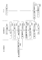
図6Aの第2情報端末5は、第1情報端末3内の第1情報記憶部21に記憶された情報を読み出す情報読出部31と、読み出した情報を記憶する第2情報記憶部32と、読み出した情報を符号化した第1符号化情報7aを生成する第1符号化部33と、第1符号化情報7aを出力装置6に出力させる第1出力制御部34と、表示部35とを有する。
情報読出部31は、例えば、NFCなどの無線回線を用いて、第1情報端末3内の第1情報記憶部21から情報を読み出す。第1符号化部33が生成する符号化情報は、QRコードやバーコードなどである。符号化情報を生成する理由は、第1情報端末3内の第1情報記憶部21に記憶されている情報は見守り対象者2の個人情報であることから、この情報を一見して把握できないようにして個人情報の保護を図るためである。なお、汎用的なQRコードやバーコードは、スマートフォン等で簡易に元の情報に復号できるため、鍵情報等のセキュアな手法で符号化を行ってもよい。
本実施形態における出力装置6は、例えばプリンタ(印刷装置)である。第2情報端末5内の第1出力制御部34は、例えばプリンタにて、第1符号化情報7aを紙媒体等の印刷媒体に印字する。この場合、第1面会者4は、見守り対象者2に面会時に、紙媒体に第1符号化情報7aを印字する。第1面会者4は、印字した第1符号化情報7aを、例えば従来から用いられている見守り情報を記録するためのノートに貼り付ける。これにより、第1面会者4は、見守り対象者2の面会時にノートに見守り情報を手書きする必要がなくなり、第1面会者4の負担が軽減する。
第2情報端末5には、情報読出部31、第1符号化部33および第1出力制御部34の各処理動作を行うアプリケーションソフトウェア(以下、第1アプリ)がインストールされている。第1面会者4が第2情報端末5上で第1アプリを実行することで、第1情報端末3から情報を読み出して、第2情報記憶部32に記憶するとともに、その情報を符号化して出力装置6に出力する一連の処理を行うことができる。
なお、第2情報端末5は、第1面会者4が見守り対象者2と会話を交わして把握した印象などを入力する第2入力部36を備えていてもよい。第2情報端末5内の第1符号化部33は、情報読出部31にて読み出された情報と、第2入力部36にて入力された情報とを符号化した第1符号化情報7aを生成してもよい。これにより、第1符号化情報7aには、見守り対象者2が自ら入力した情報だけでなく、第1面会者4が見守り対象者2に面会して取得した情報までが含まれることになり、情報の利用価値が高くなる。
第1符号化情報7aをQRコード(登録商標)やバーコードで実現する場合、記憶可能なデータ量が制限されるため、第1面会者4が見守り対象者2に面会して取得した情報まで含めることができない可能性もある。この場合、別個のQRコードやバーコードを設ければよい。すなわち、印字すべきデータ量に応じて、紙媒体に印字される第1符号化情報7aの数を任意に変更できるようにしてもよい。
また、情報読出部31にて読み出された情報に基づく第1符号化情報7aと、第2入力部36にて入力された情報に基づく第1符号化情報7aとを区別できように、それぞれ異なる表示形態で紙媒体に印字してもよい。例えば、一方の第1符号化情報7aと、他方の第1符号化情報7aとの色を変えてもよい。これにより、後に第1符号化情報7aを復号する際に、見守り対象者2が入力した情報だけを復号したり、第1面会者4が入力した情報だけを復号したりすることができる。
なお、本実施形態における出力装置6は、プリンタに限定されるものではなく、例えば情報表示装置でもよい。情報表示装置は、見守り対象者2の居宅等の面会場所に置かれているPC、タブレット端末、スマートフォン、モニタ端末などである。図7は情報表示装置37の内部構成の一例を示すブロック図である。図7の情報表示装置37は、第1符号化情報7aを記憶する第3記憶部38と、第3記憶部38に記憶された第1符号化情報7aを表示する表示部(第1表示部)39とを有する。
紙媒体に印字または情報表示装置37に表示された第1符号化情報7aは、見守り対象者2と第1面会者4以外の特定の第三者によって取得できるようにしてもよい。特定の第三者とは、見守り対象者2を見守る必要がある人間であり、具体的な一例としては、見守り対象者2の家族等の近親者や、見守り対象者2に対して何らかの医療行為を行う医療関係者などである。近親者には、身寄りのない見守り対象者2の法定代理人も含まれる。あるいは、見守り対象者2やその家族から依頼された人間も含まれる。医療関係者には、主治医や薬剤師、栄養管理士などである。以下では、このような特定の第三者をまとめて第2面会者7と呼ぶ。
第2面会者7への第1符号化情報7aの提供は、第3情報端末40により行われる。第3情報端末40は、例えば第2面会者7が所持するタブレット端末やラップトップ型PCなどである。第2面会者7は、第3情報端末40を携帯して見守り対象者2の居宅等の面会場所を訪問して面会する。なお、第3情報端末40は、見守り対象者2の居宅等の面会場所に置いていてもよい。この場合、第2面会者7は、見守り対象者2に面会した際に、第3情報端末40を操作することになる。
この他、第2情報端末5は、図6に示すように、時刻調整部51と、初期化部52を備えていてもよい。時刻調整部51は、定期的に時刻を合わせる。見守り対象者2が所持する第1情報端末3は、第2情報端末5から時刻情報を受け取るため、第2情報端末5の時刻が不正確だと、第1情報端末3の時刻も不正確になる。よって、第2情報端末5内に時刻調整部51を設けるのが望ましい。初期化部52は、新規の見守り対象者に渡される第1情報端末3の初期化を行うとともに、第1情報端末3に時刻を送信する。初期化部52を設けることで、第2情報端末5は第1情報端末3の初期化を行うことができる。
また、第2情報端末5は、確認項目情報生成部53と、確認項目情報送信部54と、管理情報生成部55とを備えていてもよい。確認項目情報生成部53は、個々の見守り対象者に固有で、第1情報端末3にて見守り対象者が入力する確認項目情報を生成する。確認項目情報の詳細は後述する。確認項目情報送信部54は、見守り対象者2に渡される第1情報端末3の初期化時に確認項目情報を送信する。管理情報生成部55は、見守り対象者を識別する第1識別情報と、見守り対象者に渡される第1情報端末3を識別する第2識別情報と、見守り対象者に固有の確認項目情報とを紐付けた管理情報を生成する。
図6Bは図5BのASIC12を内蔵した第1情報端末3に対応する第2情報端末5の内部構成を示すブロック図である。図6Bの第2情報端末5は、図6Aから第1符号化部33を省略したものである。図6Bの第2情報端末5内の情報読出部31は、ASIC12内の第1情報記憶部21に記憶された第1符号化情報を読み出す。第2情報記憶部32は、情報読出部31が読み出した第1符号化情報を記憶する。
図8は第3情報端末40の内部構成の一例を示すブロック図である。図8の第3情報端末40は、出力装置6に出力された第1符号化情報7aを読み取る情報読取部41と、読み取った第1符号化情報7aを符号化前の情報に復号する復号部42と、復号された情報を表示する表示部(第2表示部)43とを有する。
情報読取部41は、例えば第3情報端末40に内蔵されているカメラを有する。このカメラにて、第1符号化情報7aが撮影される。復号部42は、カメラの撮影画像を解析して、第1符号化情報7aを符号化前の情報に復号する。第2面会者7は、第3情報端末40の表示部43に表示される復号後の情報により、見守り対象者2が第1情報端末3に入力した情報を確認する。また、第1面会者4が第2情報端末5に入力した情報がある場合には、この情報も表示部43にて確認する。
そして、第2面会者7は、表示部43にて確認した情報を参考にしながら、見守り対象者2に面会し、必要に応じて、治療、診断、検査、問診、薬の調剤などを行う。例えば、第2面会者7が主治医であれば、表示部43にて確認した情報に基づいて、治療方法の変更や、新たな検査、あるいは薬の処方箋作成などを行う。また、第2面会者7が薬剤師であれば、表示部43にて確認した情報に基づいて、薬の調剤などを行う。
第1面会者4が操作する第2情報端末5にも、第3情報端末40と同様の情報読取部41と復号部42を設けてもよい。これにより、第1面会者4も、第2情報端末5を使って、第1符号化情報7aを読み取って復号し、復号した情報を表示部43にて確認可能となる。
第3情報端末40には、情報読取部41および復号部42の各処理動作を行うアプリケーションソフトウェア(以下、第2アプリ)がインストールされている。第2面会者7が第3情報端末40上で第2アプリを実行することで、出力装置6から情報を読み取って復号して表示部43に表示する一連の処理を行うことができる。
なお、第3情報端末40は、第2面会者7が見守り対象者2と会話を交わして把握した印象などを入力する第3入力部44と、第3入力部44にて入力された情報を符号化した第2符号化情報を生成する第2符号化部45と、第2符号化情報を出力装置6に出力させる第2出力制御部46と、を備えていてもよい。
これにより、第3情報端末40は、第2面会者7が見守り対象者2に面会して取得した情報を符号化した第2符号化情報を出力装置6に出力することができる。従って、第1面会者4や他の第2面会者7は、この情報を復号することで、第2面会者7が見守り対象者2に対してどのような印象を持ったかを把握できる。例えば、第2面会者7が主治医であれば、見守り対象者2の健康状態が良好であると判断した場合には、第1面会者4の面会間隔を長くしてもよいという情報や、薬剤師が調剤する薬の種類や量の変更を指示する情報を含む第2符号化情報を生成してもよい。
また、第3情報端末40は、見守り対象者2が第1情報端末3に入力した情報を一元的に管理する情報管理装置9に有線または無線の回線によりアクセスして、情報管理装置9が管理する情報を参照できるようにしてもよい。この場合、第3情報端末40内に通信制御部47が設けられる。
上述したように、第1面会者4は、見守りサービスを行う事業者から派遣された者である。この事業者は、見守り対象者2を管理する情報管理装置9を備えている。この情報管理装置9は、サーバやPCにて実現可能である。情報管理装置9は、各見守り対象者2の氏名や識別情報と、第1情報端末3から第2情報端末5にて取得した情報とを対応づけて管理する。
情報管理装置9は、第2情報端末5と有線または無線にて情報を送受可能である。また、情報管理装置9は、第3情報端末40と有線または無線にて情報を送受できるようにしてもよい。
新規の見守り対象者2に第1情報端末3を提供する場合には、見守りサービスの事業者が見守り対象者2の登録作業を行う。図9Aおよび図9Bは見守り対象者2の登録手続の一例を示すシーケンス図である。まず、見守りサービスの事業者が管理する情報管理装置9は、専用のアプリケーションソフトウェア(以下、第3アプリ)を起動する(ステップS1)。ログイン画面が表示されると、情報管理装置9の操作者は、予め定められたユーザIDとパスワードを入力する(ステップS2)。この場合の操作者は、例えば新規の見守り対象者2と定期的に面会する予定の第1面会者4である。あるいは、第1面会者4から依頼を受けた別の人間でもよい。
ログイン手続に成功すると、操作者は、見守り対象者の新規登録を選択する(ステップS3)。次に、新規登録画面の指示に従って、見守り対象者を識別するための見守り対象者ID(第1識別情報)を選択する(ステップS4)。次に、操作者は、見守り対象者の氏名や住所などの個人情報を登録する(ステップS5)。操作者は、情報管理装置9に登録された状態に誤りが無いことを確認する(ステップS6)。
ステップS1~S6の処理に前後して、操作者は、第2情報端末5の時刻を調整する(ステップS11)。後述するように、第2情報端末5の時刻情報が第1情報端末3に送信されるため、第2情報端末5の時刻が不正確であると、第1情報端末3の時刻も不正確になってしまう。このため、定期的に第2情報端末5の時刻を合わせる処理が必要となる。なお、第2情報端末5の時刻を合わせる具体的な処理は問わない。例えば、第2情報端末5から特定のサイトにアクセスして時刻調整を行ってもよいし、電話回線などを介して時刻調整を行ってもよい。あるいは、操作者が手動で第2情報端末5の時刻調整をできるようにしてもよい。
次に、操作者は、第2情報端末5上で専用のアプリケーションソフトウェア(以下、第4アプリ)を起動する(ステップS12)。この第4アプリに従って、操作者は、ユーザIDとパスワードを入力する(ステップS13)。次に、操作者は、第2情報端末5上で、第1情報端末3の初期登録を指示する(ステップS14)。
続いて、操作者は、第2情報端末5上で、新規に登録した見守り対象者の見守り対象者IDの取得を指示する(ステップS15)。また、操作者は、情報管理装置9に対して、登録した情報を第2情報端末5と連携させることを指示する(ステップS7)。この指示を受けて、情報管理装置9は、新規に登録した見守り対象者2の登録情報を第2情報端末5に送信する(ステップS8)。登録情報の送信は、有線と無線のいずれで行ってもよい。有線による送信は、例えばUSB(Universal Serial Bus)端子やイーサネット(登録商標)などを介した通信である。無線による送信は、例えばWiFi(登録商標)や無線LAN(Local Area Network)などを介した通信である。
第2情報端末5は、情報管理装置9から送信された登録情報を受信し、第2情報端末5内の所定の記憶部に記憶する(ステップS16)。この記憶部は、図6の第2情報記憶部32でもよいし、第2情報記憶部32とは別個に設けられる記憶部でもよい。次に、操作者は、第2情報端末5を用いて、新規の見守り対象者に固有の確認項目情報を登録する(ステップS17)。ここで、確認項目情報とは、第1情報端末3にて、特定の見守り対象者2が入力する情報であり、例えば、特定の見守り対象者2の疾病や健康状態に関する情報である。より具体的な一例としては、血圧の高い見守り対象者2であれば、血圧に関する情報を確認項目情報としてもよい。なお、ステップS17の処理は任意である。確認項目情報が必要なければ、ステップS17の処理を省略してもよい。
次に、操作者は、新規の見守り対象者2に配布する予定の第1情報端末3を手元に置いた状態で、この第1情報端末3の初期化を指示する(図9BのステップS18)。この指示は、第2情報端末5にて行われる。これにより、第2情報端末5から第1情報端末3に対して、例えば無線により、初期化情報が送信される(ステップS19)。初期化情報は、例えば、時刻情報や確認項目情報を含んでいる。
第1情報端末3は、第2情報端末5から送信された初期化情報を受信し(ステップS31)、第1情報端末3内の時刻を修正し(ステップS32)、第1情報端末3を初期化する(ステップS33)。また、第1情報端末3内に確認項目情報を設定する(ステップS34)。
例えば、図3の情報入力カード3は、健康状態として項目1~3を有し、生体情報として項目1~3を有する。これらの項目1~3の少なくとも一部は、第2情報端末5から送信された確認項目情報によって、項目の具体的な内容を任意に変更できるものであってもよい。この場合、各項目がどのような内容であるかを情報入力カード3に設定する必要がある。この処理を行うのがステップS34である。
ステップS34の処理が終了すると、第1情報端末3は、初期化が完了した旨を無線により第2情報端末5に通知する(ステップS35)。このとき、第1情報端末3は、第1情報端末3を識別するための端末IDと、第1情報端末3が管理する時刻(タイムスタンプ)とを第2情報端末5に送信する。
この通知を受けて、第2情報端末5は、管理情報を生成する(ステップS20)。ここで、管理情報とは、見守り対象者ID(第1識別情報)と、見守り対象者が所持する第1情報端末3の端末ID(第2識別情報)と、第1情報端末3に設定された確認項目情報とを紐付けた情報である。
第2情報端末5は、管理情報を有線または無線により情報管理装置9に送信する(ステップS21)。情報管理装置9は、受信した管理情報を見守り対象者DBに登録し(ステップS9)、第3アプリを終了する(ステップS10)。同様に、第2情報端末5は、管理情報を情報管理装置9に送信後に、第4アプリを終了する(ステップS22)。
図10は第2情報端末5による第1情報端末3の情報読出処理の一例を示すシーケンス図である。図10では、出力装置6としてプリンタを用いる例を示している。
まず、第1面会者4は、第2情報端末5にて第1アプリを起動する(ステップS41)。また、第1面会者4は、ステップS41に前後して、出力装置6であるプリンタも起動する(ステップS42)。
まず、第1面会者4は、第2情報端末5にて第1アプリを起動する(ステップS41)。また、第1面会者4は、ステップS41に前後して、出力装置6であるプリンタも起動する(ステップS42)。
第2情報端末5にログイン画面が表示されると、第1面会者4は、予め定められたユーザIDとパスワードを入力する(ステップS43)。メニュー画面が表示されると、第1面会者4は、メニューの中からデータ読出を選択する(ステップS44)。これにより、第2情報端末5は、例えば無線回線により、第1情報端末3に情報送信要求を送信する(ステップS45)。この要求を受信した第1情報端末3は、第1情報記憶部21に記憶されている情報を、無線回線にて第2情報端末5に送信する(ステップS46)。第2情報端末5は、第1情報端末3からの情報を受信し(ステップS47)、受信した情報を第2情報記憶部32に記憶する(ステップS48)。
次に、第1符号化部33は、受信した情報を符号化した第1符号化情報7aを生成する(ステップS49)。次に、第1出力制御部34は、第1符号化情報7aをプリンタに印字するよう指示し(ステップS50)、その後に第1アプリを終了させる(ステップS51)。この指示を受けて、プリンタは、第1符号化情報7aを紙媒体に印字し(ステップS52)、その後プリンタの電源をオフする(ステップS53)。
第1面会者4は、第1符号化情報7aが印字された紙媒体を、例えばノート7に貼り付ける。なお、ノート7に貼り付ける代わりに、紙媒体を直接ファイリングしてもよい。また、紙媒体に印字される第1符号化情報7aには、時刻情報(タイムスタンプ情報)などの付属情報を付記してもよい。付属情報は、個人情報ではないため、必ずしも符号化する必要はない。なお、図10では、第2情報端末5にて符号化を行う例を示しているが、図5BのASIC12を有する第1情報端末3と図6Bの第2情報端末5とを備えている場合には、第1情報端末3にて符号化を行うため、第2情報端末5では符号化処理を省略できる。
上述したように、第1情報端末3内の第1情報記憶部21の記憶容量が満杯になった場合は、第2情報端末5装置の指示により、第1情報記憶部21内の情報の消去が行われる。図11は第1情報記憶部21内の情報の消去処理の一例を示すシーケンス図である。第1情報端末3内の第1情報記憶部21の記憶容量が満杯になった場合は、見守り対象者2が選択ボタン6a、6b、6cを押下したときに、警告音が鳴動して、満杯になったことを見守り対象者2に報知する。第1面会者4は、見守り対象者2から第1情報記憶部21の記憶容量が満杯になったことを知らされると、第1情報記憶部21内の情報を第2情報端末5に転送した後に、第2情報端末5のメニュー画面からデータ消去を選択する(ステップS61)。これにより、第2情報端末5から無線回線にて第1情報端末3にデータ消去要求が送信される(ステップS62)。この要求を受けた第1情報端末3は、第1情報記憶部21内の全情報を消去し(ステップS63)、消去が完了した旨の情報を無線回線にて第2情報端末5に送信する(ステップS64)。この情報を受信すると、第2情報端末5の表示部35に消去が完了したことを示す情報が表示される(ステップS65)。
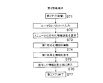
第2情報端末5または第3情報端末40は、第1符号化情報7aを復号することができる。図12は第3情報端末40による第1符号化情報7aの復号処理の一例を示すシーケンス図である。
第2面会者8は、第3情報端末40にて第2アプリを起動し(ステップS71)、ログイン画面が表示されると、ユーザIDとパスワードを入力する(ステップS72)。メニュー画面が表示されると、メニュー画面の中から符号化情報の読取を選択する(ステップS73)。第3情報端末40内の情報読取部41に対応するカメラは、第1符号化情報7aを撮影する(ステップS74)。第3情報端末40内の復号部42は、撮影画像を解析して、第1符号化情報7aを復号する(ステップS75)。次に、第3情報端末40は、復号した情報を表示部43に表示する(ステップS76)。その後、必要に応じて、復号した情報を保存するなどした後に、第2アプリを終了させる(ステップS77)。
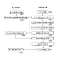
第1面会者4が見守り対象者に面会して、第1情報端末3内の情報を第2情報端末5にて読み出した後、この情報は、第1面会者4が事業所に持ち帰った後、情報管理装置9にて一元的に管理される。図13は第2情報端末5内の情報を情報管理装置9にて一元的に管理する処理の一例を示すシーケンス図である。
第1面会者4は、第1情報端末3を起動し(ステップS81)、第1情報端末3と情報管理装置9とを接続する(ステップS82)。この接続は、有線でもよいし、無線でもよい。
また、ステップS81,S82の処理に並行して、所定の管理者は、第1情報管理装置9にて専用のアプリケーションソフトウェアを起動し(ステップS83)、ログインIDとパスワードを入力した後(ステップS84)、メニュー画面の中から見守り対象者2の情報読出を選択する(ステップS85)。
次に、インポートファイルと保存先を指定する(ステップS86)。そして、第2情報端末5に情報読出要求を送信する(ステップS87)。この要求を受けて、第2情報端末5は、第1情報端末3から読み出した見守り対象者2の情報を情報管理装置9に送信する(ステップS88)。情報管理装置9は、受信した情報を、指定したインポートファイルに保存して、ステップS86で指定した保存先に転送する(ステップS89)。転送が終了すると、保存が完了したことを情報管理装置9の表示部に表示し(ステップS90)、アプリを終了させるとともに(ステップS91)、第2情報端末5の電源をオフする(ステップS92)。
このように、本実施形態では、見守り対象者2が第1情報端末3にて入力したボタン操作情報を第1情報端末3または第2情報端末5にて符号化して出力装置6に出力させるため、ネットワーク環境が整備されていない状況下でも、第1情報端末3に記憶された情報を有効活用することができる。また、出力装置6が出力する情報は、第1情報端末3内の情報を符号化したものであり、見守り対象者2の個人情報を保護しつつ、見守り対象者2を見守るのに必要な情報を共有できる。
第2面会者8は、出力装置6が出力する第1符号化情報7aを簡易な手順で復号できるため、復号された情報を確認しながら、見守り対象者2に対して各種のサービスを提供できる。また、第1面会者4および第2面会者8は、見守り対象者2との面会により取得した新たな情報を符号化して出力装置6に出力させることも可能となり、見守り対象者2を見守るのに必要な情報を蓄積することができる。
上述した実施形態で説明した見守り情報共有システム1の少なくとも一部は、ハードウェアで構成してもよいし、ソフトウェアで構成してもよい。ソフトウェアで構成する場合には、見守り情報共有システム1の少なくとも一部の機能を実現するプログラムをフレキシブルディスクやCD-ROM等の記録媒体に収納し、コンピュータに読み込ませて実行させてもよい。記録媒体は、磁気ディスクや光ディスク等の着脱可能なものに限定されず、ハードディスク装置やメモリなどの固定型の記録媒体でもよい。
また、見守り情報共有システム1の少なくとも一部の機能を実現するプログラムを、インターネット等の通信回線(無線通信も含む)を介して頒布してもよい。さらに、同プログラムを暗号化したり、変調をかけたり、圧縮した状態で、インターネット等の有線回線や無線回線を介して、あるいは記録媒体に収納して頒布してもよい。
本開示の態様は、上述した個々の実施形態に限定されるものではなく、当業者が想到しうる種々の変形も含むものであり、本開示の効果も上述した内容に限定されない。すなわち、特許請求の範囲に規定された内容およびその均等物から導き出される本開示の概念的な思想と趣旨を逸脱しない範囲で種々の追加、変更および部分的削除が可能である。
1 見守り情報共有システム、3 第1情報端末、5 第2情報端末、6 出力装置、10 薄型モジュール部品、12 ASIC、21 第1情報記憶部、22 制御部、23 インタフェース部、31 情報読出部、32 第2情報記憶部、33 第1符号化部、34 第1出力制御部、35 表示部、40 第3情報端末、41 情報読取部、42 復号部、43 表示部
Claims (11)
- 見守り対象者が所持する第1情報端末と、前記見守り対象者に面会する第1面会者が操作する第2情報端末と、出力装置と、を備えた見守り情報共有システムであって、
前記第1情報端末は、
見守り対象者が情報を入力する第1入力部と、
前記第1入力部にて入力された情報を記憶する第1情報記憶部と、を有し、
前記第2情報端末は、
前記第1情報記憶部に記憶された情報を読み出す情報読出部と、
前記情報読出部にて読み出された情報を記憶する第2情報記憶部と、
前記情報読出部にて読み出された情報を符号化した第1符号化情報を生成する第1符号化部と、
前記第1符号化情報を前記出力装置に出力させる第1出力制御部と、を有する、見守り情報共有システム。 - 見守り対象者が所持する第1情報端末と、前記見守り対象者に面会する第1面会者が操作する第2情報端末と、出力装置と、を備えた見守り情報共有システムであって、
前記第1情報端末は、
見守り対象者が情報を入力する第1入力部と、
前記第1入力部にて入力された情報を符号化した第1符号化情報を生成する第1符号化部と、
前記第1符号化情報を記憶する第1情報記憶部と、を有し、
前記第2情報端末は、
前記第1情報記憶部に記憶された前記第1符号化情報を読み出す情報読出部と、
前記情報読出部にて読み出された前記第1符号化情報を記憶する第2情報記憶部と、
前記第1符号化情報を前記出力装置に出力させる第1出力制御部と、を有する、見守り情報共有システム。 - 前記第2情報端末は、
前記見守り対象者に面会した前記第1面会者が情報を入力する第2入力部を有し、
前記第1符号化部は、前記情報読出部にて読み出された情報と、前記第2入力部にて入力された情報と、を符号化した前記第1符号化情報を生成する請求項1に記載の見守り情報共有システム。 - 前記出力装置は、印刷装置であり、
前記第1面会者は、前記見守り対象者に面会時に、前記第1符号化情報を前記印刷装置で印刷した印刷媒体を作製する請求項1乃至3のいずれか一項に記載の見守り情報共有システム。 - 前記出力装置は、情報表示装置であり、
前記情報表示装置は、
前記第1符号化情報を記憶する第3記憶部と、
前記第3記憶部に記憶された前記第1符号化情報を表示する第1表示部と、を有する請求項1乃至3のいずれか一項に記載の見守り情報共有システム。 - 前記見守り対象者に面会する第2面会者が操作する第3情報端末を備え、
前記第3情報端末は、
前記出力装置に出力された前記第1符号化情報を読み取る情報読取部と、
前記情報読取部で読み取った前記第1符号化情報を符号化前の情報に復号する復号部と、
前記復号された情報を表示する第2表示部と、を有する請求項1乃至5のいずれかに記載の見守り情報共有システム。 - 前記第3情報端末は、
前記見守り対象者に面会した前記第2面会者が情報を入力する第3入力部と、
前記第3入力部にて入力された情報を符号化した第2符号化情報を生成する第2符号化部と、
前記第2符号化情報を前記出力装置に出力させる第2出力制御部と、を有する請求項6に記載の情報共有システム。 - 前記第2情報記憶部に記憶された情報を管理する情報管理装置を備え、
前記第3情報端末は、有線または無線の回線を介して、前記情報管理装置が管理する情報にアクセスする通信制御部を有する請求項6または7に記載の見守り情報共有システム。 - 前記第2情報端末は、定期的に前記見守り対象者に面会して前記第1情報記憶部に記憶された情報を収集するサービスを行うサービス事業者により所持され、
前記第3情報端末は、前記見守り対象者の治療および薬の調剤の少なくとも一方を行う医療関係者と、前記見守り対象者の近親者と、の少なくとも一方により所持される請求項6乃至8のいずれか一項に記載の見守り情報共有システム。 - 前記第2情報端末は、
定期的に時刻を合わせる時刻調整部と、
新規の見守り対象者に渡される前記第1情報端末の初期化を行うとともに、前記第1情報端末に前記時刻を送信する初期化部と、を有する請求項1乃至9のいずれか一項に記載の見守り情報共有システム。 - 前記第2情報端末は、
個々の見守り対象者に固有で、前記第1情報端末にて前記見守り対象者が入力する確認項目情報を生成する確認項目情報生成部と、
前記見守り対象者に渡される前記第1情報端末の初期化時に前記確認項目情報を送信する確認項目情報送信部と、
前記見守り対象者を識別する第1識別情報と、前記見守り対象者に渡される前記第1情報端末を識別する第2識別情報と、前記見守り対象者に固有の前記確認項目情報とを紐付けた管理情報を生成する管理情報生成部と、を有する請求項10に記載の見守り情報供給システム。
Priority Applications (1)
| Application Number | Priority Date | Filing Date | Title |
|---|---|---|---|
| JP2017526393A JP6701580B2 (ja) | 2015-06-30 | 2016-06-29 | 見守り情報共有システム |
Applications Claiming Priority (2)
| Application Number | Priority Date | Filing Date | Title |
|---|---|---|---|
| JP2015-131793 | 2015-06-30 | ||
| JP2015131793 | 2015-06-30 |
Publications (1)
| Publication Number | Publication Date |
|---|---|
| WO2017002848A1 true WO2017002848A1 (ja) | 2017-01-05 |
Family
ID=57608769
Family Applications (1)
| Application Number | Title | Priority Date | Filing Date |
|---|---|---|---|
| PCT/JP2016/069257 Ceased WO2017002848A1 (ja) | 2015-06-30 | 2016-06-29 | 見守り情報共有システム |
Country Status (2)
| Country | Link |
|---|---|
| JP (1) | JP6701580B2 (ja) |
| WO (1) | WO2017002848A1 (ja) |
Citations (5)
| Publication number | Priority date | Publication date | Assignee | Title |
|---|---|---|---|---|
| JPH1125193A (ja) * | 1997-06-27 | 1999-01-29 | Mitsubishi Electric Corp | 訪問看護支援システムにおける携帯端末 |
| JP2002123611A (ja) * | 2000-10-16 | 2002-04-26 | Tamio Imaizumi | メッセージ管理装置および方法 |
| JP2003085476A (ja) * | 2001-09-11 | 2003-03-20 | Dainippon Printing Co Ltd | 2次元バーコードを利用した電子書籍データの配布方法 |
| JP2008269304A (ja) * | 2007-04-20 | 2008-11-06 | Sensor:Kk | ケータイ@ヘルスケア(楽楽健康管理) |
| JP2015108894A (ja) * | 2013-12-03 | 2015-06-11 | 大日本印刷株式会社 | 見守りシステム |
-
2016
- 2016-06-29 WO PCT/JP2016/069257 patent/WO2017002848A1/ja not_active Ceased
- 2016-06-29 JP JP2017526393A patent/JP6701580B2/ja not_active Expired - Fee Related
Patent Citations (5)
| Publication number | Priority date | Publication date | Assignee | Title |
|---|---|---|---|---|
| JPH1125193A (ja) * | 1997-06-27 | 1999-01-29 | Mitsubishi Electric Corp | 訪問看護支援システムにおける携帯端末 |
| JP2002123611A (ja) * | 2000-10-16 | 2002-04-26 | Tamio Imaizumi | メッセージ管理装置および方法 |
| JP2003085476A (ja) * | 2001-09-11 | 2003-03-20 | Dainippon Printing Co Ltd | 2次元バーコードを利用した電子書籍データの配布方法 |
| JP2008269304A (ja) * | 2007-04-20 | 2008-11-06 | Sensor:Kk | ケータイ@ヘルスケア(楽楽健康管理) |
| JP2015108894A (ja) * | 2013-12-03 | 2015-06-11 | 大日本印刷株式会社 | 見守りシステム |
Also Published As
| Publication number | Publication date |
|---|---|
| JP6701580B2 (ja) | 2020-05-27 |
| JPWO2017002848A1 (ja) | 2018-04-19 |
Similar Documents
| Publication | Publication Date | Title |
|---|---|---|
| CN100544668C (zh) | 数据处理装置、测量装置和数据收集方法 | |
| US8925812B2 (en) | Medical device tracking system and apparatus | |
| US20080306772A1 (en) | System and Method for Providing a Personal Internet of Objects and Information | |
| CN103250132A (zh) | 工作流增强设备、系统以及方法 | |
| JP5760031B2 (ja) | 情報管理システム、装置、方法およびプログラム | |
| CN115394396A (zh) | 一种基于云端服务器的医院门诊应急服务系统及方法 | |
| CN104537466A (zh) | 幼儿园安全健康管理的方法及系统 | |
| CN208570121U (zh) | 远程健康自助服务终端设备 | |
| JP6701580B2 (ja) | 見守り情報共有システム | |
| KR101296915B1 (ko) | 공용 혈압계를 이용한 개인혈압정보 관리시스템 및 그 방법 | |
| JP5108393B2 (ja) | 医療情報処理システム | |
| WO2018003077A1 (ja) | 画面共有遠隔診察システム、画面共有遠隔診察方法、および画面共有遠隔診察プログラム | |
| CN203911931U (zh) | 用于信息交互的服务器终端、客户终端以及信息交互系统 | |
| JP7091586B2 (ja) | ポイント管理サーバ及び登録プログラム | |
| CN100568294C (zh) | 工作信息处理系统、装置和方法 | |
| CN102708292A (zh) | 胶囊内窥镜图像管理及显示系统与方法 | |
| JP2006331115A (ja) | 介護実績管理方法、介護実績管理システム、コンピュータプログラム、プログラム格納媒体 | |
| KR102283682B1 (ko) | 만성질환자 응급 관리 시스템 및 그 관리 방법 | |
| US20170109575A1 (en) | Safety label replication and management systems | |
| TWM517881U (zh) | 遠距醫療量測管理設備 | |
| JP2015219699A (ja) | 画像管理システム、画像管理方法及び撮像装置 | |
| JP3207466U (ja) | スキャナ型ゲートウエイ機器 | |
| JP7631811B2 (ja) | センシングデータ管理システム、センシングデータ送信方法、センシング装置、情報通信端末およびプログラム | |
| TW201401215A (zh) | 醫院報到暨排隊叫號管理系統 | |
| Weng | NFC Convenient Application: a case of personal health record |
Legal Events
| Date | Code | Title | Description |
|---|---|---|---|
| 121 | Ep: the epo has been informed by wipo that ep was designated in this application |
Ref document number: 16817956 Country of ref document: EP Kind code of ref document: A1 |
|
| ENP | Entry into the national phase |
Ref document number: 2017526393 Country of ref document: JP Kind code of ref document: A |
|
| NENP | Non-entry into the national phase |
Ref country code: DE |
|
| 122 | Ep: pct application non-entry in european phase |
Ref document number: 16817956 Country of ref document: EP Kind code of ref document: A1 |