WO2017002757A1 - Magnus-type thrust generating device - Google Patents
Magnus-type thrust generating device Download PDFInfo
- Publication number
- WO2017002757A1 WO2017002757A1 PCT/JP2016/069000 JP2016069000W WO2017002757A1 WO 2017002757 A1 WO2017002757 A1 WO 2017002757A1 JP 2016069000 W JP2016069000 W JP 2016069000W WO 2017002757 A1 WO2017002757 A1 WO 2017002757A1
- Authority
- WO
- WIPO (PCT)
- Prior art keywords
- flow
- magnus
- cylindrical
- type thrust
- wing
- Prior art date
Links
- 230000002401 inhibitory effect Effects 0.000 description 41
- 230000001133 acceleration Effects 0.000 description 26
- 230000005764 inhibitory process Effects 0.000 description 20
- 239000012530 fluid Substances 0.000 description 8
- 230000007423 decrease Effects 0.000 description 7
- 230000000694 effects Effects 0.000 description 5
- 238000000034 method Methods 0.000 description 4
- 230000000903 blocking effect Effects 0.000 description 2
- 230000004048 modification Effects 0.000 description 2
- 238000012986 modification Methods 0.000 description 2
- 239000002131 composite material Substances 0.000 description 1
- 238000010586 diagram Methods 0.000 description 1
- 238000010248 power generation Methods 0.000 description 1
- 230000001141 propulsive effect Effects 0.000 description 1
- 230000001629 suppression Effects 0.000 description 1
Images


Classifications
-
- F—MECHANICAL ENGINEERING; LIGHTING; HEATING; WEAPONS; BLASTING
- F03—MACHINES OR ENGINES FOR LIQUIDS; WIND, SPRING, OR WEIGHT MOTORS; PRODUCING MECHANICAL POWER OR A REACTIVE PROPULSIVE THRUST, NOT OTHERWISE PROVIDED FOR
- F03D—WIND MOTORS
- F03D3/00—Wind motors with rotation axis substantially perpendicular to the air flow entering the rotor
- F03D3/005—Wind motors with rotation axis substantially perpendicular to the air flow entering the rotor the axis being vertical
- F03D3/007—Wind motors with rotation axis substantially perpendicular to the air flow entering the rotor the axis being vertical using the Magnus effect
-
- F—MECHANICAL ENGINEERING; LIGHTING; HEATING; WEAPONS; BLASTING
- F03—MACHINES OR ENGINES FOR LIQUIDS; WIND, SPRING, OR WEIGHT MOTORS; PRODUCING MECHANICAL POWER OR A REACTIVE PROPULSIVE THRUST, NOT OTHERWISE PROVIDED FOR
- F03B—MACHINES OR ENGINES FOR LIQUIDS
- F03B13/00—Adaptations of machines or engines for special use; Combinations of machines or engines with driving or driven apparatus; Power stations or aggregates
- F03B13/12—Adaptations of machines or engines for special use; Combinations of machines or engines with driving or driven apparatus; Power stations or aggregates characterised by using wave or tide energy
- F03B13/26—Adaptations of machines or engines for special use; Combinations of machines or engines with driving or driven apparatus; Power stations or aggregates characterised by using wave or tide energy using tide energy
- F03B13/264—Adaptations of machines or engines for special use; Combinations of machines or engines with driving or driven apparatus; Power stations or aggregates characterised by using wave or tide energy using tide energy using the horizontal flow of water resulting from tide movement
-
- F—MECHANICAL ENGINEERING; LIGHTING; HEATING; WEAPONS; BLASTING
- F03—MACHINES OR ENGINES FOR LIQUIDS; WIND, SPRING, OR WEIGHT MOTORS; PRODUCING MECHANICAL POWER OR A REACTIVE PROPULSIVE THRUST, NOT OTHERWISE PROVIDED FOR
- F03B—MACHINES OR ENGINES FOR LIQUIDS
- F03B17/00—Other machines or engines
- F03B17/06—Other machines or engines using liquid flow with predominantly kinetic energy conversion, e.g. of swinging-flap type, "run-of-river", "ultra-low head"
- F03B17/062—Other machines or engines using liquid flow with predominantly kinetic energy conversion, e.g. of swinging-flap type, "run-of-river", "ultra-low head" with rotation axis substantially at right angle to flow direction
-
- F—MECHANICAL ENGINEERING; LIGHTING; HEATING; WEAPONS; BLASTING
- F03—MACHINES OR ENGINES FOR LIQUIDS; WIND, SPRING, OR WEIGHT MOTORS; PRODUCING MECHANICAL POWER OR A REACTIVE PROPULSIVE THRUST, NOT OTHERWISE PROVIDED FOR
- F03D—WIND MOTORS
- F03D1/00—Wind motors with rotation axis substantially parallel to the air flow entering the rotor
- F03D1/06—Rotors
- F03D1/0601—Rotors using the Magnus effect
-
- F—MECHANICAL ENGINEERING; LIGHTING; HEATING; WEAPONS; BLASTING
- F03—MACHINES OR ENGINES FOR LIQUIDS; WIND, SPRING, OR WEIGHT MOTORS; PRODUCING MECHANICAL POWER OR A REACTIVE PROPULSIVE THRUST, NOT OTHERWISE PROVIDED FOR
- F03D—WIND MOTORS
- F03D3/00—Wind motors with rotation axis substantially perpendicular to the air flow entering the rotor
- F03D3/06—Rotors
- F03D3/061—Rotors characterised by their aerodynamic shape, e.g. aerofoil profiles
-
- F—MECHANICAL ENGINEERING; LIGHTING; HEATING; WEAPONS; BLASTING
- F03—MACHINES OR ENGINES FOR LIQUIDS; WIND, SPRING, OR WEIGHT MOTORS; PRODUCING MECHANICAL POWER OR A REACTIVE PROPULSIVE THRUST, NOT OTHERWISE PROVIDED FOR
- F03D—WIND MOTORS
- F03D5/00—Other wind motors
- F03D5/04—Other wind motors the wind-engaging parts being attached to carriages running on tracks or the like
-
- F—MECHANICAL ENGINEERING; LIGHTING; HEATING; WEAPONS; BLASTING
- F03—MACHINES OR ENGINES FOR LIQUIDS; WIND, SPRING, OR WEIGHT MOTORS; PRODUCING MECHANICAL POWER OR A REACTIVE PROPULSIVE THRUST, NOT OTHERWISE PROVIDED FOR
- F03D—WIND MOTORS
- F03D80/00—Details, components or accessories not provided for in groups F03D1/00 - F03D17/00
-
- F—MECHANICAL ENGINEERING; LIGHTING; HEATING; WEAPONS; BLASTING
- F03—MACHINES OR ENGINES FOR LIQUIDS; WIND, SPRING, OR WEIGHT MOTORS; PRODUCING MECHANICAL POWER OR A REACTIVE PROPULSIVE THRUST, NOT OTHERWISE PROVIDED FOR
- F03G—SPRING, WEIGHT, INERTIA OR LIKE MOTORS; MECHANICAL-POWER PRODUCING DEVICES OR MECHANISMS, NOT OTHERWISE PROVIDED FOR OR USING ENERGY SOURCES NOT OTHERWISE PROVIDED FOR
- F03G7/00—Mechanical-power-producing mechanisms, not otherwise provided for or using energy sources not otherwise provided for
-
- F—MECHANICAL ENGINEERING; LIGHTING; HEATING; WEAPONS; BLASTING
- F05—INDEXING SCHEMES RELATING TO ENGINES OR PUMPS IN VARIOUS SUBCLASSES OF CLASSES F01-F04
- F05B—INDEXING SCHEME RELATING TO WIND, SPRING, WEIGHT, INERTIA OR LIKE MOTORS, TO MACHINES OR ENGINES FOR LIQUIDS COVERED BY SUBCLASSES F03B, F03D AND F03G
- F05B2210/00—Working fluid
- F05B2210/16—Air or water being indistinctly used as working fluid, i.e. the machine can work equally with air or water without any modification
-
- F—MECHANICAL ENGINEERING; LIGHTING; HEATING; WEAPONS; BLASTING
- F05—INDEXING SCHEMES RELATING TO ENGINES OR PUMPS IN VARIOUS SUBCLASSES OF CLASSES F01-F04
- F05B—INDEXING SCHEME RELATING TO WIND, SPRING, WEIGHT, INERTIA OR LIKE MOTORS, TO MACHINES OR ENGINES FOR LIQUIDS COVERED BY SUBCLASSES F03B, F03D AND F03G
- F05B2240/00—Components
- F05B2240/20—Rotors
- F05B2240/201—Rotors using the Magnus-effect
-
- Y—GENERAL TAGGING OF NEW TECHNOLOGICAL DEVELOPMENTS; GENERAL TAGGING OF CROSS-SECTIONAL TECHNOLOGIES SPANNING OVER SEVERAL SECTIONS OF THE IPC; TECHNICAL SUBJECTS COVERED BY FORMER USPC CROSS-REFERENCE ART COLLECTIONS [XRACs] AND DIGESTS
- Y02—TECHNOLOGIES OR APPLICATIONS FOR MITIGATION OR ADAPTATION AGAINST CLIMATE CHANGE
- Y02B—CLIMATE CHANGE MITIGATION TECHNOLOGIES RELATED TO BUILDINGS, e.g. HOUSING, HOUSE APPLIANCES OR RELATED END-USER APPLICATIONS
- Y02B10/00—Integration of renewable energy sources in buildings
- Y02B10/30—Wind power
-
- Y—GENERAL TAGGING OF NEW TECHNOLOGICAL DEVELOPMENTS; GENERAL TAGGING OF CROSS-SECTIONAL TECHNOLOGIES SPANNING OVER SEVERAL SECTIONS OF THE IPC; TECHNICAL SUBJECTS COVERED BY FORMER USPC CROSS-REFERENCE ART COLLECTIONS [XRACs] AND DIGESTS
- Y02—TECHNOLOGIES OR APPLICATIONS FOR MITIGATION OR ADAPTATION AGAINST CLIMATE CHANGE
- Y02E—REDUCTION OF GREENHOUSE GAS [GHG] EMISSIONS, RELATED TO ENERGY GENERATION, TRANSMISSION OR DISTRIBUTION
- Y02E10/00—Energy generation through renewable energy sources
- Y02E10/20—Hydro energy
-
- Y—GENERAL TAGGING OF NEW TECHNOLOGICAL DEVELOPMENTS; GENERAL TAGGING OF CROSS-SECTIONAL TECHNOLOGIES SPANNING OVER SEVERAL SECTIONS OF THE IPC; TECHNICAL SUBJECTS COVERED BY FORMER USPC CROSS-REFERENCE ART COLLECTIONS [XRACs] AND DIGESTS
- Y02—TECHNOLOGIES OR APPLICATIONS FOR MITIGATION OR ADAPTATION AGAINST CLIMATE CHANGE
- Y02E—REDUCTION OF GREENHOUSE GAS [GHG] EMISSIONS, RELATED TO ENERGY GENERATION, TRANSMISSION OR DISTRIBUTION
- Y02E10/00—Energy generation through renewable energy sources
- Y02E10/30—Energy from the sea, e.g. using wave energy or salinity gradient
-
- Y—GENERAL TAGGING OF NEW TECHNOLOGICAL DEVELOPMENTS; GENERAL TAGGING OF CROSS-SECTIONAL TECHNOLOGIES SPANNING OVER SEVERAL SECTIONS OF THE IPC; TECHNICAL SUBJECTS COVERED BY FORMER USPC CROSS-REFERENCE ART COLLECTIONS [XRACs] AND DIGESTS
- Y02—TECHNOLOGIES OR APPLICATIONS FOR MITIGATION OR ADAPTATION AGAINST CLIMATE CHANGE
- Y02E—REDUCTION OF GREENHOUSE GAS [GHG] EMISSIONS, RELATED TO ENERGY GENERATION, TRANSMISSION OR DISTRIBUTION
- Y02E10/00—Energy generation through renewable energy sources
- Y02E10/70—Wind energy
- Y02E10/72—Wind turbines with rotation axis in wind direction
-
- Y—GENERAL TAGGING OF NEW TECHNOLOGICAL DEVELOPMENTS; GENERAL TAGGING OF CROSS-SECTIONAL TECHNOLOGIES SPANNING OVER SEVERAL SECTIONS OF THE IPC; TECHNICAL SUBJECTS COVERED BY FORMER USPC CROSS-REFERENCE ART COLLECTIONS [XRACs] AND DIGESTS
- Y02—TECHNOLOGIES OR APPLICATIONS FOR MITIGATION OR ADAPTATION AGAINST CLIMATE CHANGE
- Y02E—REDUCTION OF GREENHOUSE GAS [GHG] EMISSIONS, RELATED TO ENERGY GENERATION, TRANSMISSION OR DISTRIBUTION
- Y02E10/00—Energy generation through renewable energy sources
- Y02E10/70—Wind energy
- Y02E10/74—Wind turbines with rotation axis perpendicular to the wind direction
Definitions
- the present invention includes a thrust generator using a Magnus force generated by a substantially cylindrical cylindrical blade that rotates in a fluid, a wind power rotator that is rotated using the thrust generator, a hydraulic rotator, a tidal rotator, and The present invention relates to a fluid machine such as a wind power generator, a hydroelectric power generator, or a tidal power generator that rotates a power generator using the thrust generator.
- Patent Document 1 WO 2013/014848
- the composite Magnus wing as shown in Patent Document 2 aims to obtain the rotational torque of the horizontal axis wind turbine and the lift of the aircraft by the Magnus force.
- the direction of the Magnus force generated when the cylindrical blade is rotated in one direction is the same direction on the windward and windward sides of the wind turbine, so the rotational torques of the vertical axis wind turbines are opposite to each other As a result, the horizontal axis wind turbine can not be used as the vertical wind turbine as it is.
- Patent Document 5 discloses a method of suppressing the reverse direction Magnus force generated on the windward wind side by shielding the cylindrical blade on the windward wind down side with the wind speed rectifying device provided in the wind turbine central portion.
- Patent Document 6 the direction of the Magnus force is switched by changing the rotation direction of the cylindrical blade on the windward side and the windward side of the wind turbine, and a wind turbine rotational torque in the same direction is generated on the windward and windward sides of the wind turbine. It is shown.
- Patent Document 7 shows a method of generating a wind turbine rotational torque in the same direction on the windward side and the windward side of a wind turbine by making a pair of cylindrical blades and reversing the rotation directions of the respective blades.
- the present invention can generate thrust capable of efficiently controlling the magnitude of the Magnus force generated on a cylindrical blade according to the direction of flow acting on the cylindrical blade with a simple structure. It aims at providing an apparatus.
- the first present invention is A first member having a first rotation axis and rotatable about the first rotation axis; A second member disposed on the rear side in the traveling direction of the first member; A Magnus-type thrust generator having The first member and the second member are rotatable about the second rotation axis, On a plane perpendicular to the first rotation axis of the Magnus-type thrust generator, Let L be the distance from the first rotation axis to the farthest part of the surface of the first member, When the distance from the first rotation axis to the nearest part of the surface of the second member is M, (M ⁇ L) / L ⁇ 2
- the Magnus-type thrust generator is characterized in that
- the second invention is It is a Magnus-type thrust generator according to a first aspect of the present invention, wherein the second member has a substantially plate shape extending in a direction opposite to the traveling direction of the first member.
- the third invention is It is the Magnus-type thrust generator according to the first and second aspects of the present invention, wherein the second member has a substantially streamlined shape extending in a direction opposite to the direction in which the first member travels.
- the fourth invention is The second member is a magnus-type thrust generator according to any one of the first to third inventions, characterized in that the second member has irregularities on its surface.
- the fifth invention is The first member is a magnus-type thrust generator according to any one of the first to fourth inventions, characterized in that the first member has asperities optionally on its surface.
- the sixth invention is It is a wind power rotating device, a hydraulic rotating device, or a tidal power rotating device using any of the Magnus-type thrust generating devices according to any of the first to fifth inventions.
- magnus force The pressure difference between the flow accelerating side and the flow decelerating side generates a thrust (magnus force), so the magnus force is a force perpendicular to the flow direction.
- the pressure on the surface of the first member is approximately the same as that in the case without the second member, and as a result, the first member surface on the flow acceleration side Since the pressure difference does not change significantly, the magnitude of the Magnus force generated in the first member is approximately the same as in the case where the flow reduction side of the first member does not have the second member.
- the position of the second member is relatively the first according to the direction of flow with respect to the direction of travel of the first member. Either the state on the flow accelerating side of the member or the state on the flow decelerating side.
- the first invention is applied to a vertical axis wind turbine, and the rotation direction of the wind turbine, that is, the traveling direction of the first member is the clockwise direction of the wind turbine.
- the first member In order to set the direction of the Magnus force generated in the first member on the windward side of the wind turbine to the direction in which the whole wind turbine rotates clockwise, the first member may be rotated clockwise.
- the second member provided on the back side with respect to the advancing direction of the first member is in the range of the flow reduction side of the first member.
- the magnitude of the Magnus force in the clockwise direction of the wind turbine generated in the first member on the windward side of the wind turbine is approximately the same as that without the second member.
- the direction of the Magnus force generated in the first member rotating clockwise is the direction in which the entire wind turbine is rotated counterclockwise.
- the second member provided on the back side with respect to the advancing direction of the first member is in the range of the flow acceleration side of the first member.
- the magnitude of the Magnus force in the counterclockwise direction of the wind turbine generated in the first member on the downwind side of the wind turbine is reduced as compared with the case without the second member.
- the distance between the second member and the surface of the first member is equal to or less than the diameter of the first member, it is possible to further enhance the flow deceleration effect when the second member is on the flow acceleration side of the first member. It is possible to control the magnitude of the Magnus force generated in the first member more efficiently.
- a thrust generating device capable of efficiently controlling the magnitude of the Magnus force generated in the first member according to the direction of the flow acting on the first member by the simple structure of the second member. Can be provided.
- the second member by forming the second member into a substantially plate shape extending in the direction opposite to the advancing direction of the first member, the second member can be used as the first member according to the flow direction acting on the first member. It becomes possible to control the magnitude of the generated Magnus force more efficiently.
- the second invention is applied to a vertical axis wind turbine
- the rotation direction of the wind turbine that is, the traveling direction of the first member is the clockwise direction of the wind turbine.
- the second member provided on the back side with respect to the advancing direction of the first member has an azimuth angle of 0 degree.
- the flow of the first member It is located at a position of 90 degrees from the center of the reduction side toward the windward side, that is, at the boundary with the flow acceleration side.
- the end of the second member is the first as the azimuth angle increases in the range of 0 to 90 degrees.
- the region on the flow acceleration side of the member is blocked, and as a result of the flow on the flow acceleration side being blocked, the Magnus force generated in the first member is reduced.
- the end of the second member can be used even if the azimuth angle is increased in the range of 0 degrees to 90 degrees. It becomes difficult to inhibit the region on the flow acceleration side, and it is possible to prevent the reduction of the Magnus force generated in the first member.
- the end of the second member is less likely to inhibit the flow acceleration region, and the Magnus force generated in the first member Similar to the second aspect of the present invention in that the decrease can be prevented, the fluid resistance of the second member can be reduced by making the shape of the second member substantially streamlined.
- the flow resistance of the second member can be reduced by providing the flow control means with any unevenness such as grooves, dimples, protrusions, vortex generators, etc. on the surface of the second member. Noise such as wind noise can be reduced.
- the Magnus force generated in the cylindrical wing 1 can be increased by having arbitrary irregularities such as protrusions or notches on the surface of the first member.
- the magnus-type thrust generator according to the first to sixth aspects of the present invention has a vertical axis, or a wind power rotating device having a horizontal axis perpendicular to the flow, a hydraulic rotating device or a tidal power rotating device.
- the simple structure of the second member suppresses the Magnus force generated in the downstream direction when the first member is rotated in one direction, in the direction to reversely rotate the rotating device, and the efficiency of the rotating device. Can be improved.
- FIG. 12 is a plan view showing a modification of the flow inhibition means of the Magnus-type thrust generator according to Embodiment 2 of the present invention.
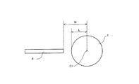
- FIG. 7 is a diagram showing the distance from the first rotation axis to the farthest part of the surface of the cylindrical wing and the distance from the first rotation axis to the nearest part of the surface of the flow inhibiting means.
- (A) to (f) is a plan view of a cylindrical wing in a fourth embodiment according to the present invention. These are front views of the cylindrical wing
- Embodiment 1 The following describes a Magnus-type thrust generator according to Embodiment 1 of the present invention.
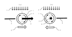
- FIGS. 1 (a) to 1 (b) are plan views of a Magnus-type thrust generator according to a first embodiment of the present invention.
- the flow direction 5 is the downward direction in the drawing
- the advancing direction 3 of the cylindrical wing 1 is the right direction in the drawing
- the back side with respect to the advancing direction 3 of the cylindrical wing 1 On the left side, a plate-shaped flow inhibiting means 4 is provided at a position not exceeding the diameter of the cylindrical wing 1 from the surface of the cylindrical wing 1.
- the cylindrical wing 1 corresponds to an example of the first member of the present invention
- the flow inhibiting means 4 corresponds to an example of the second member of the present invention.
- the back side with respect to the traveling direction 3 of the cylindrical wing 1 is a plane including the first rotation axis C1 of the cylindrical wing 1 (first member) and is two by a plane perpendicular to the traveling direction 3
- the portion on the left side of the alternate long and short dash line It corresponds to ".
- the Magnus force 6 is generated in the right direction perpendicular to the flow direction 5.
- the flow inhibiting means 4 since the flow inhibiting means 4 is located on the flow deceleration side of the cylindrical blade 1, the flow inhibiting means 4 inhibits the flow on the flow deceleration side and decelerates, but for the side where the flow is originally decelerated,
- the pressure on the surface of the cylindrical wing 1 on the flow reduction side is the same as in the case without the flow inhibiting means 4 and the pressure difference with the surface of the cylindrical wing 1 on the flow acceleration side is also the same as in the case without the flow inhibiting means 4
- the magnitude of the Magnus force 6 generated in the cylindrical blade 1 becomes comparable to that in the case without the flow inhibiting means 4.
- a plate-shaped flow inhibiting means 4 is provided at a portion (on the right side of the alternate long and short dash line).
- the Magnus force 6 is generated in the right direction perpendicular to the flow direction 5.
- the traveling direction 3 of the cylindrical wing 1 and the direction of the Magnus force 6 are opposite.
- the flow inhibiting means 4 since the flow inhibiting means 4 is located on the flow accelerating side of the cylindrical blade, the flow inhibiting means 4 inhibits the flow on the flow accelerating side and decelerates, so the pressure on the surface of the cylindrical wing 1 on the flow accelerating side As a result, it becomes difficult to lower the pressure difference with the surface of the cylindrical blade 1 on the flow reduction side, and as a result, the magnitude of the Magnus force 6 generated in the cylindrical blade 1 decreases.
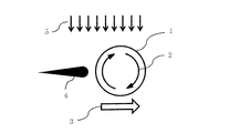
- the shape of the flow inhibition means 4 may not be a linear shape, but may be a substantially arc shape as shown in FIG. 2 (a) or a substantially V shape as shown in FIG. 2 (b).
- the drag of the flow inhibiting means 4 can also be used as an auxiliary propulsive force of the cylindrical wing 1 by making the shape of the flow inhibiting means 4 into a substantially arc shape or a substantially V shape.
- the thickness of the flow inhibiting means 4 does not have to be constant either, and may have a substantially streamlined shape as shown in FIG. 2 (c).
- the flow inhibiting means 4 is at least an entity of an arbitrary shape, and it may be any entity that can affect the flow on the surface of the cylindrical blade 1. It is obvious that it will have some influence on the surface flow.
- the Magnus-type thrust generator according to the second embodiment has the same basic configuration as the first embodiment, but the shape of the flow inhibiting means is a substantially plate shape extending in the direction opposite to the traveling direction of the cylindrical wing 1 The point is different.
- FIGS. 3 (a) to 3 (b) are plan views of a Magnus-type thrust generator according to a second embodiment of the present invention.
- the flow direction 5 is the downward direction in the drawing
- the advancing direction 3 of the cylindrical wing 1 is the right direction in the drawing, and the back side with respect to the advancing direction 3 of the cylindrical wing 1
- On the left side (the left side of the alternate long and short dash line), a plate shape extending in the opposite direction to the traveling direction 3 of the cylindrical wing, that is, in the left direction in the drawing Flow inhibiting means 4 is provided.
- the cylindrical wing 1 corresponds to an example of the first member of the present invention
- the flow inhibiting means 4 corresponds to an example of the second member of the present invention.
- the flow inhibiting means 4 is located on the flow deceleration side of the cylindrical wing 1, the magnitude of the Magnus force 6 generated in the cylindrical wing 1 is also the same as in the case without the flow inhibiting means 4. This is the same as the case of FIG. 1 (a) in the first embodiment.
- the traveling direction 3 of the cylindrical wing and the direction of the Magnus force 6 are opposite.
- the flow inhibiting means 4 is positioned on the flow acceleration side of the cylindrical wing 1, the magnitude of the Magnus force 6 generated in the cylindrical wing 1 is also reduced as shown in FIG. 1 (b) in the first embodiment. The same as in the case of.
- the effect of the second embodiment is different from that of the first embodiment in the case where the flow direction 5 and the azimuth angle 13 of the Magnus-type thrust generator of the present invention are not 0 degrees as shown in FIG.
- the end of the flow inhibition means 4 may The part to the right of the alternate long and short dash line parallel to the direction 5, that is, the region on the flow acceleration side of the cylindrical blade 1, becomes obstructed, the flow on the flow acceleration side is blocked, and the Magnus force 6 generated in the cylindrical blade 1 is large. Decrease.
- the flow inhibition means 4 has a substantially plate shape having a small width in the direction perpendicular to the traveling direction 3 of the cylindrical blade as in the second embodiment, whereby the azimuth angle 13 is obtained. Regardless of this, the end of the flow inhibiting means 4 is less likely to inhibit the area on the flow acceleration side, and the reduction of the magnitude of the Magnus force 6 generated in the cylindrical wing 1 can be prevented.
- the shape of the flow inhibition means 4 extended in the direction opposite to the traveling direction 3 of the cylindrical wing may be a substantially streamlined shape as shown in FIG. 5 instead of a plate shape.
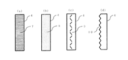
- groove shapes 7 as shown in FIG. 6 (a), dimples or protrusions 8 as shown in FIG. 6 (b), and vortex generator shapes as shown in FIG. A flow control means with any unevenness such as 9 may be provided.
- These flow control means can reduce the fluid resistance of the flow inhibiting means 4 and reduce noise such as wind noise.
- a flow control means 10 with any unevenness such as a projection or a notch as shown in FIG. 6 (d) may be provided.
- These flow control means can reduce noise such as wind noise.
- FIG. 6 is directed to the flow inhibiting means 4, similarly to this, the surface of the cylindrical wing 1 may optionally be provided with irregularities, and the effect obtained by doing so is also an action inhibiting means. This is the same as in the case where asperities are provided at 4 arbitrarily.
- the groove shape 7, the dimple or protrusion 8, the vortex generator shape 9 and the flow control means 10 correspond to an example of the unevenness of the second member of the present invention.
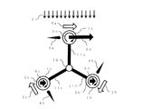
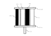
- FIG. 7 is a plan view of a wind power rotating device according to a third embodiment of the present invention.
- a plurality of support members 11a, 11b and 11c are provided on the second rotation shaft 12 of the wind turbine, and each of the support members 11a, 11b and 11c has cylindrical wings 1a, 1b and 1c, and each of the cylinders Flow inhibiting means 4a, 4b, 4c are provided at a distance from the surface of the wing not exceeding the diameter of the cylindrical wing.
- the cylindrical wings 1a, 1b, 1c correspond to an example of the first member of the present invention
- the flow inhibiting means 4a, 4b, 4c correspond to an example of the second member of the present invention.
- the cylindrical blades 1a, 1b, 1c and the flow inhibiting means 4a, 4b, 4c are rotatable about the second rotation shaft 12 via the support members 11a, 11b, 11c.
- the number of the support member, the cylindrical wing, and the number of flow inhibiting means provided on the second rotation shaft 12 is three in combination, but this is an example, and it is not three but other It may be any number of.
- cylindrical wings 1a, 1b, 1c and the flow inhibiting means 4a, 4b, 4c may be supported at each end by a pair of support members 11d, 11e.
- magnus forces 6a, 6b, 6c are generated in the cylindrical blades 1a, 1b, 1c respectively, and the wind power rotating device is centered on the second rotation shaft 12 Rotate to.
- a motor may be installed at the base of each cylindrical blade, or one motor may be installed near the second rotation shaft 12, and each motor may be The rotational force may be transmitted to the cylindrical wing.
- the direction of the Magnus force 6a generated on the cylindrical wing 1a on the windward side of the wind power rotating device is in the right direction on the paper surface, that is, the direction of rotating the wind power rotating device clockwise.
- the flow inhibiting means 4a is located in the range on the flow deceleration side of the cylindrical wing 1a, the magnitude of the Magnus force 6a generated in the cylindrical wing 1a is approximately the same as that without the flow inhibiting means 4a. .
- the directions of the magnus forces 6b and 6c generated on the cylindrical wings 1b and 1c on the downwind side of the wind power rotating device are also in the right direction in the drawing, that is, the direction of rotating the wind power rotating device counterclockwise.
- the flow inhibition means 4b and 4c provided on the back side with respect to the traveling direction 3b and 3c of the cylindrical wing are respectively located in the range on the flow acceleration side of the cylindrical wing 1b and 1c.
- the cylindrical blade can be
- the rotation force of the wind power rotation device can be improved by suppressing the Magnus force in the direction to reversely rotate the wind power rotation device, which is generated downstream when rotating in the direction.
- a generator By attaching a generator to the second rotating shaft 12 in the third embodiment, it can be used as a wind power generator.
- the rotational force of the second rotating shaft 12 can be used as a driving means of a rotating machine such as a pump.
- the direction of rotation of the wind power rotating device may be counterclockwise.
- the direction of rotation of each cylindrical blade may be counterclockwise, and the flow inhibiting means may be provided on the back side with respect to the direction of movement of the cylindrical blades.
- Embodiment 3 although demonstrated as an example of a wind-force rotation apparatus, the same may be said of the case of a hydraulic rotation apparatus and a tidal power rotation apparatus.
- FIG. 9 is an experiment conducted at a wind speed of 5 m / s using a ribbed cylindrical blade having a diameter of 100 mm and a plate-shaped flow blocking means having a width of 100 mm and a thickness of 5 mm extending in the direction opposite to the traveling direction of the cylindrical blade. It is an experimental result obtained as a result.
- FIG. 10 is a view showing a distance L from the first rotation axis C1 to the farthest part of the surface of the cylindrical wing 1 and a distance M from the first rotation axis C1 to the nearest part of the surface of the flow inhibition means 4.
- the horizontal axis of the graph in FIG. 9 is the radius of the cylindrical blade L, the distance from the center of the cylindrical blade to the flow inhibiting means as M, and the distance between the cylindrical wing and the flow inhibiting means (ML) divided by L
- the vertical axis is the measured value of the Magnus force
- the "airflow deceleration side” and “airflow acceleration side” refer to the flow inhibition means provided only on the air flow deceleration side and the flow inhibition means only on the air flow acceleration side.
- the Magnus force generated in the case (corresponding to the case of FIG. 1 (a) and the case of FIG. 1 (b), etc.) respectively means “difference” means “air flow deceleration side” and “air flow” It means the difference of the Magnus force generated in the case of “acceleration side”.
- (ML) / L it is desirable to set (ML) / L to a value smaller than 2. More preferably, it is desirable that (ML) / L be a value smaller than 1. Furthermore, preferably, it is desirable that (ML) / L be a value smaller than 0.4.
- Embodiment 4 Next, a Magnus-type thrust generator according to a fourth embodiment of the present invention will be described.
- 11 (a) to 11 (f) are plan views of the cylindrical wing 1 according to the fourth embodiment of the present invention.
- the cross-sectional shape of the cylindrical blade 1 is different.
- the cylindrical wing 1 in the fourth embodiment optionally has unevenness on the surface.
- three cross-sectionally triangular ribs 13 are formed on the surface in parallel with the rotation axis C1.
- the number of ribs 13 may be any number, but a total of about 3 to 8 is preferable.
- the height of the rib 13 is preferably 10% or less of the diameter of the cylindrical wing 1.
- the distance L from the first rotation axis C1 to the farthest part of the surface of the cylindrical wing 1 is from the first rotation axis C1 to the highest position of the rib 13 as shown in FIG. 11 (a).
- two ribs 13 having a triangular cross-sectional shape and two ribs 14 having a rectangular cross-sectional shape are formed in parallel to the rotation axis C1.
- the number of ribs 13 and 14 may be any number, but a total of about 3 to 8 is preferable.
- the height of the ribs 13 and 14 is preferably 10% or less of the diameter of the cylindrical wing 1.
- the distance L from the first rotation axis C1 to the farthest part of the surface of the cylindrical wing 1 is from the first rotation axis C1 to the highest position of the ribs 13, 14 as shown in FIG. 11 (b).
- notches 15 having a circular arc shape in cross section are formed on the surface in parallel with the rotation axis C1.
- the number of notches 15 may be any number, but a total of about 3 to 8 is preferable.
- the depth of the notch 15 is preferably 10% or less of the diameter of the cylindrical blade 1.
- the distance L from the first rotation axis C1 to the farthest part of the surface of the cylindrical wing 1 is from the first rotation axis C1 to the surface, as shown in FIG. 11 (c).
- notches 15 having a circular arc shape in cross section and four notches 16 having a rectangular shape in cross section are formed in parallel to the rotation axis C1.
- the number of the notches 15, 16 may be any number, but a total of about 3 to 8 is preferable.
- the depth of the notches 15 and 16 is preferably 10% or less of the diameter of the cylindrical blade 1.
- the distance L from the first rotation axis C1 to the farthest part of the surface of the cylindrical wing 1 is from the first rotation axis C1 to the surface, as shown in FIG. 11 (d).
- each rib 14 having a rectangular cross section and four notches 16 having a rectangular cross section are formed in parallel to the rotation axis C1.
- the number of ribs 14 and notches 16 may be any number, but a total of about 3 to 8 is preferable.
- the height of the rib 14 and the depth of the notch 16 are preferably 10% or less of the diameter of the cylindrical blade 1.
- the distance L from the first rotation axis C1 to the farthest part of the surface of the cylindrical wing 1 is from the first rotation axis C1 to the highest position of the rib 14, as shown in FIG. 11 (e).
- two ribs 14 having a rectangular cross-section, two ribs 17 having an arc-shaped cross section and two notches 18 having a triangular cross-section are formed parallel to the rotation axis C1 There is.
- the number of ribs 14 and 17 and the number of notches 18 may be any number, but a total of about 3 to 8 is preferable.
- the height of the ribs 14 and 17 and the depth of the notch 18 are preferably 10% or less of the diameter of the cylindrical blade 1.
- the distance L from the first rotation axis C1 to the farthest part of the surface of the cylindrical wing 1 is from the first rotation axis C1 to the highest position of the rib 14, as shown in FIG. 11 (f).
- the cylindrical wing 1 corresponds to an example of the first member of the present invention.
- the ribs 13, 14, 17 and the notches 15, 16, 18 correspond to an example of the unevenness of the first member of the present invention.
- the surface of the cylindrical wing 1 has any unevenness such as projections or notches, whereby the Magnus force generated in the cylindrical wing 1 can be increased.
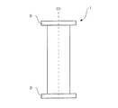
- FIG. 12 is a front view of a cylindrical wing 1 according to a fifth embodiment of the present invention.
- large-diameter portions D are formed at both end portions of the cylindrical wing 1 in the first rotation axis C1 direction.
- the large diameter portion D rotates integrally with the cylindrical wing 1.
- the flow near the center and near both ends of the cylindrical wing 1 is made uniform, and the Magnus force generated in the cylindrical wing 1 is increased.
- the Magnus-type thrust generator of the present invention exerts an effect of efficiently controlling the magnitude of the Magnus force generated in the cylindrical blade according to the direction of the flow acting on the cylindrical blade by a simple structure, and the wind power rotation It is useful as a device, a hydraulic rotating device, a tidal rotating device, and a thrust generating device for driving a fluid machine such as a wind power generator, a hydroelectric generator, a tidal power generator and the like.
Abstract
Description
第一回転軸を有し、前記第一回転軸周りに回転可能な第一部材と、
前記第一部材の進行方向の背面側に配置された第二部材と、
を有するマグナス式推力発生装置であって、
前記第一部材および前記第二部材は、前記第二回転軸周りに回転可能であり、
前記マグナス式推力発生装置の前記第一回転軸に垂直な平面上において、
前記第一回転軸から前記第一部材の表面の最も遠い部位までの距離をLとし、
前記第一回転軸から前記第二部材の表面の最も近い部位までの距離をMとした場合、
(M-L)/L<2
を充たすことを特徴とするマグナス式推力発生装置である。 In order to achieve the above object, the first present invention is
A first member having a first rotation axis and rotatable about the first rotation axis;
A second member disposed on the rear side in the traveling direction of the first member;
A Magnus-type thrust generator having
The first member and the second member are rotatable about the second rotation axis,
On a plane perpendicular to the first rotation axis of the Magnus-type thrust generator,
Let L be the distance from the first rotation axis to the farthest part of the surface of the first member,
When the distance from the first rotation axis to the nearest part of the surface of the second member is M,
(M−L) / L <2
The Magnus-type thrust generator is characterized in that
前記第二部材が、前記第一部材の進行方向と逆方向に伸びた略板形状である、第1の本発明のマグナス式推力発生装置である。 The second invention is
It is a Magnus-type thrust generator according to a first aspect of the present invention, wherein the second member has a substantially plate shape extending in a direction opposite to the traveling direction of the first member.
前記第二部材が、前記第一部材の進行方向と逆方向に伸びた略流線型形状である、第1および第2の本発明のマグナス式推力発生装置である。 The third invention is
It is the Magnus-type thrust generator according to the first and second aspects of the present invention, wherein the second member has a substantially streamlined shape extending in a direction opposite to the direction in which the first member travels.
前記第二部材は、その表面に任意に凹凸を有することを特徴とする、第1ないし第3の本発明のいずれかのマグナス式推力発生装置である。 The fourth invention is
The second member is a magnus-type thrust generator according to any one of the first to third inventions, characterized in that the second member has irregularities on its surface.
前記第一部材は、その表面に任意に凹凸を有することを特徴とする、第1ないし第4の本発明のいずれかのマグナス式推力発生装置である。 The fifth invention is
The first member is a magnus-type thrust generator according to any one of the first to fourth inventions, characterized in that the first member has asperities optionally on its surface.
第1から第5の本発明のいずれかのマグナス式推力発生装置を用いた風力回転装置、水力回転装置または潮力回転装置である。 The sixth invention is
It is a wind power rotating device, a hydraulic rotating device, or a tidal power rotating device using any of the Magnus-type thrust generating devices according to any of the first to fifth inventions.
以下に、本発明にかかる実施の形態1におけるマグナス式推力発生装置について説明する。
The following describes a Magnus-type thrust generator according to
次に、本発明にかかる実施の形態2におけるマグナス式推力発生装置について説明する。 Second Embodiment
Next, a Magnus-type thrust generator according to a second embodiment of the present invention will be described.
次に、本発明にかかる実施の形態3におけるマグナス式推力発生装置を用いた風力回転装置について説明する。 Third Embodiment
Next, a wind power rotating device using a Magnus-type thrust generator according to a third embodiment of the present invention will be described.
図9は、直径100mmのリブ付き円筒翼と、円筒翼の進行方向と逆方向に伸びた、幅100mm、厚さ5mmの板形状の流れ阻害手段を用いて、風速5m/sで実験を行った結果得られた実験結果である。図10は、第一回転軸C1から円筒翼1の表面の最も遠い部位までの距離Lと第一回転軸C1から流れ阻害手段4の表面の最も近い部位までの距離Mを示す図である。 (Experimental data)
FIG. 9 is an experiment conducted at a wind speed of 5 m / s using a ribbed cylindrical blade having a diameter of 100 mm and a plate-shaped flow blocking means having a width of 100 mm and a thickness of 5 mm extending in the direction opposite to the traveling direction of the cylindrical blade. It is an experimental result obtained as a result. FIG. 10 is a view showing a distance L from the first rotation axis C1 to the farthest part of the surface of the
次に、本発明にかかる実施の形態4におけるマグナス式推力発生装置について説明する。
Next, a Magnus-type thrust generator according to a fourth embodiment of the present invention will be described.
次に、本発明にかかる実施の形態5におけるマグナス式推力発生装置について説明する。 Fifth Embodiment
Next, a Magnus-type thrust generator according to a fifth embodiment of the present invention will be described.
2、2a、2b、2c 円筒翼の回転方向
3、3a、3b、3c 円筒翼の進行方向
4、4a、4b、4c 流れ阻害手段
5 流れの方向
6、6a、6b、6c マグナス力
7 溝形状
8 ディンプルまたは突起物
9 ボルテックスジェネレータ形状
10 突起物または切り欠き
11、11a、11b、11c、11d、11e 支持部材
12 第二回転軸
13 マグナス式推力発生装置のアジマス角 1, 1a, 1b,
Claims (6)
- 第一回転軸を有し、前記第一回転軸周りに回転可能な第一部材と、
前記第一部材の進行方向の背面側に配置された第二部材と、
を有するマグナス式推力発生装置であって、
前記第一部材および前記第二部材は、第二回転軸周りに回転可能であり、
前記マグナス式推力発生装置の前記第一回転軸に垂直な平面上において、
前記第一回転軸から前記第一部材の表面の最も遠い部位までの距離をLとし、
前記第一回転軸から前記第二部材の表面の最も近い部位までの距離をMとした場合、
(M-L)/L<2
を充たすことを特徴とするマグナス式推力発生装置。 A first member having a first rotation axis and rotatable about the first rotation axis;
A second member disposed on the rear side in the traveling direction of the first member;
A Magnus-type thrust generator having
The first member and the second member are rotatable about a second rotation axis,
On a plane perpendicular to the first rotation axis of the Magnus-type thrust generator,
Let L be the distance from the first rotation axis to the farthest part of the surface of the first member,
When the distance from the first rotation axis to the nearest part of the surface of the second member is M,
(M−L) / L <2
Magnus-type thrust generator characterized in that - 前記第二部材が、前記第一部材の進行方向と逆方向に伸びた略板形状である、請求項1に記載のマグナス式推力発生装置。 The Magnus-type thrust generator according to claim 1, wherein the second member has a substantially plate shape extended in a direction opposite to the advancing direction of the first member.
- 前記第二部材が、前記第一部材の進行方向と逆方向に伸びた略流線型形状である、請求項1および2のいずれかに記載のマグナス式推力発生装置。 The Magnus-type thrust generator according to any one of claims 1 and 2, wherein the second member has a substantially streamlined shape extending in a direction opposite to the traveling direction of the first member.
- 前記第二部材は、その表面に任意に凹凸を有することを特徴とする、請求項1ないし3のいずれかに記載のマグナス式推力発生装置。 The Magnus-type thrust generator according to any one of claims 1 to 3, wherein the second member optionally has irregularities on its surface.
- 前記第一部材は、その表面に任意に凹凸を有することを特徴とする、請求項1ないし4のいずれかに記載のマグナス式推力発生装置。 The Magnus-type thrust generator according to any one of claims 1 to 4, wherein the first member optionally has irregularities on the surface thereof.
- 請求項1ないし5のいずれかに記載のマグナス式推力発生装置を用いた風力回転装置、水力回転装置または潮力回転装置。 A wind power rotating device, a hydraulic power rotating device or a tidal power rotating device using the Magnus-type thrust generator according to any one of claims 1 to 5.
Priority Applications (14)
| Application Number | Priority Date | Filing Date | Title |
|---|---|---|---|
| AU2016288158A AU2016288158B2 (en) | 2015-07-01 | 2016-06-27 | Magnus-type thrust generating device |
| CA2988381A CA2988381C (en) | 2015-07-01 | 2016-06-27 | Magnus type thrust generating device |
| ES16817865T ES2794565T3 (en) | 2015-07-01 | 2016-06-27 | Magnus type thrust generating device |
| PL16817865T PL3318754T3 (en) | 2015-07-01 | 2016-06-27 | Magnus-type thrust generating device |
| US15/736,572 US10443564B2 (en) | 2015-07-01 | 2016-06-27 | Magnus type thrust generating device |
| EP16817865.5A EP3318754B1 (en) | 2015-07-01 | 2016-06-27 | Magnus-type thrust generating device |
| CN201680039038.7A CN107850054B (en) | 2015-07-01 | 2016-06-27 | Magnus formula thrust inducing device |
| DK16817865.5T DK3318754T3 (en) | 2015-07-01 | 2016-06-27 | Pressure generating device of the Magnus type |
| RU2018103739A RU2689862C1 (en) | 2015-07-01 | 2016-06-27 | Traction-generating device by magnus effect type and rotary device using it |
| BR112017026906-6A BR112017026906B1 (en) | 2015-07-01 | 2016-06-27 | MAGNUS TYPE THRUST GENERATING DEVICE AND WIND POWER ROTARY DEVICE, HYDRAULIC DEVICE OR TIDAL POWER ROTARY DEVICE |
| JP2017521610A JP6175594B2 (en) | 2015-07-01 | 2016-06-27 | Magnus thrust generator |
| MX2017015715A MX2017015715A (en) | 2015-07-01 | 2016-06-27 | Magnus-type thrust generating device. |
| ZA2017/08261A ZA201708261B (en) | 2015-07-01 | 2017-12-05 | Magnus-type thrust generating device |
| PH12017550149A PH12017550149A1 (en) | 2015-07-01 | 2017-12-21 | Magnus type thrust generating device |
Applications Claiming Priority (2)
| Application Number | Priority Date | Filing Date | Title |
|---|---|---|---|
| JP2015133148 | 2015-07-01 | ||
| JP2015-133148 | 2015-07-01 |
Publications (1)
| Publication Number | Publication Date |
|---|---|
| WO2017002757A1 true WO2017002757A1 (en) | 2017-01-05 |
Family
ID=57608379
Family Applications (1)
| Application Number | Title | Priority Date | Filing Date |
|---|---|---|---|
| PCT/JP2016/069000 WO2017002757A1 (en) | 2015-07-01 | 2016-06-27 | Magnus-type thrust generating device |
Country Status (15)
| Country | Link |
|---|---|
| US (1) | US10443564B2 (en) |
| EP (1) | EP3318754B1 (en) |
| JP (1) | JP6175594B2 (en) |
| CN (1) | CN107850054B (en) |
| AU (1) | AU2016288158B2 (en) |
| BR (1) | BR112017026906B1 (en) |
| CA (1) | CA2988381C (en) |
| DK (1) | DK3318754T3 (en) |
| ES (1) | ES2794565T3 (en) |
| MX (1) | MX2017015715A (en) |
| PH (1) | PH12017550149A1 (en) |
| PL (1) | PL3318754T3 (en) |
| RU (1) | RU2689862C1 (en) |
| WO (1) | WO2017002757A1 (en) |
| ZA (1) | ZA201708261B (en) |
Cited By (11)
| Publication number | Priority date | Publication date | Assignee | Title |
|---|---|---|---|---|
| JP6213905B1 (en) * | 2017-05-18 | 2017-10-18 | 株式会社光風エネルギー | Mobile installation power generator |
| JP2020016167A (en) * | 2018-07-24 | 2020-01-30 | 株式会社チャレナジー | Magnus type thrust generation device, wind power rotation device, water power rotation device and tidal power rotation device using magnus type thrust generation device, and wind power generator, water power generator and tidal power generator using magnus type thrust generation device |
| JP2020016169A (en) * | 2018-07-24 | 2020-01-30 | 株式会社チャレナジー | Magnus type thrust generation device, wind power rotation device, water power rotation device and tidal power generation device using magnus type thrust generation device, and wind power generator, water power generator and tidal power generator using magnus type thrust generation device |
| JP2020016168A (en) * | 2018-07-24 | 2020-01-30 | 株式会社チャレナジー | Magnus type thrust generation device, wind power rotation device, water power rotation device and tidal power rotation device using magnus type thrust generation device, and wind power generator, water power generator and tidal power generator using magnus type thrust power generation device |
| JP2021042696A (en) * | 2019-09-10 | 2021-03-18 | 株式会社チャレナジー | Magnus thrust generator, wind power rotation device using the magnus thrust generator, water power rotation device, tidal power rotation device, and wind power generator, water power generator and tidal power generator using the magnus thrust generator |
| JP2022136492A (en) * | 2021-03-08 | 2022-09-21 | 株式会社チャレナジー | Magnus type thrust generating device, wind rotary device, hydraulic rotary device, and tidal rotary device with magnus type thrust generating device, and wind generator, hydraulic generator, and tidal generator with magnus type thrust generating device |
| JP2022136490A (en) * | 2021-03-08 | 2022-09-21 | 株式会社チャレナジー | Magnus type thrust generating device, wind rotary device, hydraulic rotary device, and tidal rotary device with magnus type thrust generating device, and wind generator, hydraulic generator, and tidal generator with magnus type thrust generating device |
| JP2022136491A (en) * | 2021-03-08 | 2022-09-21 | 株式会社チャレナジー | Magnus type thrust generating device, wind rotary device, hydraulic rotary device, and tidal rotary device with magnus type thrust generating device, and wind generator, hydraulic generator, and tidal generator with magnus type thrust generating device |
| JP2022136493A (en) * | 2021-03-08 | 2022-09-21 | 株式会社チャレナジー | Magnus type thrust generating device, wind rotary device, hydraulic rotary device, and tidal rotary device with magnus type thrust generating device, and wind generator, hydraulic generator, and tidal generator with magnus type thrust generating device |
| JP2022136468A (en) * | 2021-03-08 | 2022-09-21 | 株式会社チャレナジー | Magnus type thrust generating device, wind rotary device, hydraulic rotary device, and tidal rotary device with magnus type thrust generating device, and wind generator, hydraulic generator, and tidal generator with magnus type thrust generating device |
| JP2022136469A (en) * | 2021-03-08 | 2022-09-21 | 株式会社チャレナジー | Magnus type thrust generating device, wind rotary device, hydraulic rotary device, and tidal rotary device with magnus type thrust generating device, and wind generator, hydraulic generator, and tidal generator with magnus type thrust generating device |
Families Citing this family (9)
| Publication number | Priority date | Publication date | Assignee | Title |
|---|---|---|---|---|
| US10598187B2 (en) * | 2017-08-22 | 2020-03-24 | Asia Vital Components Co., Ltd. | Heat-dissipation fan with cylindrical fan blades |
| FR3082893B1 (en) * | 2018-06-22 | 2020-07-10 | Philippe Girault | VERTICAL WIND TURBINE. |
| JP7094018B2 (en) * | 2019-09-30 | 2022-07-01 | 株式会社チャレナジー | Magnus type thrust generator, wind power generator using the Magnus type thrust generator, hydraulic power rotation device, tidal power rotation device, and wind power generator, hydroelectric power generator, tidal power generation using the Magnus type thrust generator. Machine |
| TWI710698B (en) * | 2019-12-03 | 2020-11-21 | 周中奇 | Vertical axis fluid energy converting device |
| CN111486050B (en) * | 2020-03-05 | 2022-04-15 | 天津大学 | Deformable power generation sail and unmanned exploration ship carrying same |
| CN112918205B (en) * | 2021-04-07 | 2023-01-31 | 青海云天无人机科技有限公司 | Self-propelled type drilling platform special for marshland with buoyancy device |
| CN115539293B (en) * | 2022-09-21 | 2023-12-12 | 石家庄铁道大学 | Magnus wind wheel and wind turbine |
| CN115324819B (en) * | 2022-09-21 | 2023-12-12 | 石家庄铁道大学 | Magnus type vertical axis wind wheel and wind turbine |
| CN116928011B (en) * | 2023-08-02 | 2024-02-20 | 石家庄铁道大学 | Magnus vertical axis wind turbine |
Citations (5)
| Publication number | Priority date | Publication date | Assignee | Title |
|---|---|---|---|---|
| US1791731A (en) * | 1928-07-23 | 1931-02-10 | Madaras Rotor Power Corp | Wind engine |
| JPS5540257A (en) * | 1978-09-13 | 1980-03-21 | Takehiro Nishi | Windmill improve dynamic lift by means of guide vane |
| JP2007085327A (en) * | 2004-02-09 | 2007-04-05 | Mekaro Akita:Kk | Magnus type wind power generator |
| JP2008175070A (en) * | 2007-01-16 | 2008-07-31 | Kansai Electric Power Co Inc:The | Vertical shaft magnus type wind power generator |
| JP2010121518A (en) * | 2008-11-19 | 2010-06-03 | Mitsubishi Heavy Ind Ltd | Vertical shaft magnus type wind turbine generator |
Family Cites Families (21)
| Publication number | Priority date | Publication date | Assignee | Title |
|---|---|---|---|---|
| FR608280A (en) * | 1925-12-21 | 1926-07-23 | Vertical axis wind motor | |
| US2344515A (en) * | 1941-01-17 | 1944-03-21 | Henry P Massey | Means and method for increasing the magnus effect |
| JPS56501018A (en) | 1979-08-06 | 1981-07-23 | ||
| US4366386A (en) * | 1981-05-11 | 1982-12-28 | Hanson Thomas F | Magnus air turbine system |
| US4576581A (en) * | 1981-11-30 | 1986-03-18 | Borg John L | Reversible Magnus propeller |
| US4446379A (en) * | 1983-02-17 | 1984-05-01 | Borg John L | Magnus effect power generator |
| US6097104A (en) * | 1999-01-19 | 2000-08-01 | Russell; Thomas H. | Hybrid energy recovery system |
| RU2213883C2 (en) * | 2001-08-22 | 2003-10-10 | Соловьев Александр Петрович | Magnus-type sectional rotor |
| GB2386160A (en) | 2002-01-04 | 2003-09-10 | Technologies Ltd Ocean | Variable geometry magnus effect turbine |
| JP3962755B2 (en) * | 2004-02-09 | 2007-08-22 | 株式会社 メカロ秋田 | Magnus type wind power generator |
| DE102005001236A1 (en) | 2005-01-11 | 2006-07-20 | Gerd Lukoschus | Wind power system with rotary cylinder on rotary base plate generates power by Magnus effect with rotary cylinders in horizontal rotary base plate |
| JP2008082185A (en) | 2006-09-26 | 2008-04-10 | Kansai Electric Power Co Inc:The | Wind power generation device |
| JP2008106619A (en) | 2006-10-23 | 2008-05-08 | Kansai Electric Power Co Inc:The | Composite magnus wing |
| US7989973B2 (en) * | 2006-12-22 | 2011-08-02 | Birkestrand Orville J | Fluid-responsive oscillation power generation method and apparatus |
| EP2185811A2 (en) | 2007-08-02 | 2010-05-19 | Joel S. Douglas | Magnus force fluid flow energy harvester |
| US7781905B2 (en) * | 2007-11-13 | 2010-08-24 | Edwin Newman | Turbulence reduction around magnus rotors |
| JP2010143530A (en) | 2008-12-22 | 2010-07-01 | Toyota Motor Corp | Aerodynamic controller for vehicle |
| US8492921B2 (en) * | 2009-01-26 | 2013-07-23 | Joel S Douglas | Rotary magnus energy harvester |
| DE102010008061A1 (en) * | 2010-02-16 | 2011-12-15 | Erwin Becker | Circulating roller wind turbine and method for generating electricity from wind energy |
| JP5209826B1 (en) | 2011-07-22 | 2013-06-12 | 敦史 清水 | Vertical axis type Magnus wind generator |
| EP2602479A1 (en) * | 2011-12-09 | 2013-06-12 | Forschungsinstitut für naturgerechtes Leben GmbH | Combination wind power assembly |
-
2016
- 2016-06-27 ES ES16817865T patent/ES2794565T3/en active Active
- 2016-06-27 JP JP2017521610A patent/JP6175594B2/en active Active
- 2016-06-27 WO PCT/JP2016/069000 patent/WO2017002757A1/en active Application Filing
- 2016-06-27 RU RU2018103739A patent/RU2689862C1/en active
- 2016-06-27 CA CA2988381A patent/CA2988381C/en active Active
- 2016-06-27 MX MX2017015715A patent/MX2017015715A/en unknown
- 2016-06-27 BR BR112017026906-6A patent/BR112017026906B1/en active IP Right Grant
- 2016-06-27 AU AU2016288158A patent/AU2016288158B2/en active Active
- 2016-06-27 DK DK16817865.5T patent/DK3318754T3/en active
- 2016-06-27 US US15/736,572 patent/US10443564B2/en active Active
- 2016-06-27 PL PL16817865T patent/PL3318754T3/en unknown
- 2016-06-27 EP EP16817865.5A patent/EP3318754B1/en active Active
- 2016-06-27 CN CN201680039038.7A patent/CN107850054B/en active Active
-
2017
- 2017-12-05 ZA ZA2017/08261A patent/ZA201708261B/en unknown
- 2017-12-21 PH PH12017550149A patent/PH12017550149A1/en unknown
Patent Citations (5)
| Publication number | Priority date | Publication date | Assignee | Title |
|---|---|---|---|---|
| US1791731A (en) * | 1928-07-23 | 1931-02-10 | Madaras Rotor Power Corp | Wind engine |
| JPS5540257A (en) * | 1978-09-13 | 1980-03-21 | Takehiro Nishi | Windmill improve dynamic lift by means of guide vane |
| JP2007085327A (en) * | 2004-02-09 | 2007-04-05 | Mekaro Akita:Kk | Magnus type wind power generator |
| JP2008175070A (en) * | 2007-01-16 | 2008-07-31 | Kansai Electric Power Co Inc:The | Vertical shaft magnus type wind power generator |
| JP2010121518A (en) * | 2008-11-19 | 2010-06-03 | Mitsubishi Heavy Ind Ltd | Vertical shaft magnus type wind turbine generator |
Cited By (18)
| Publication number | Priority date | Publication date | Assignee | Title |
|---|---|---|---|---|
| JP6213905B1 (en) * | 2017-05-18 | 2017-10-18 | 株式会社光風エネルギー | Mobile installation power generator |
| JP2018193943A (en) * | 2017-05-18 | 2018-12-06 | 株式会社光風エネルギー | Moving body installation-type power generation device |
| JP7161748B2 (en) | 2018-07-24 | 2022-10-27 | 株式会社チャレナジー | Magnus type thrust generator, wind power generator, hydraulic power generator, tidal power generator using the Magnus type thrust generator, and wind power generator, water power generator, tidal power generator using the Magnus type thrust generator |
| JP2020016167A (en) * | 2018-07-24 | 2020-01-30 | 株式会社チャレナジー | Magnus type thrust generation device, wind power rotation device, water power rotation device and tidal power rotation device using magnus type thrust generation device, and wind power generator, water power generator and tidal power generator using magnus type thrust generation device |
| JP2020016168A (en) * | 2018-07-24 | 2020-01-30 | 株式会社チャレナジー | Magnus type thrust generation device, wind power rotation device, water power rotation device and tidal power rotation device using magnus type thrust generation device, and wind power generator, water power generator and tidal power generator using magnus type thrust power generation device |
| JP2020016169A (en) * | 2018-07-24 | 2020-01-30 | 株式会社チャレナジー | Magnus type thrust generation device, wind power rotation device, water power rotation device and tidal power generation device using magnus type thrust generation device, and wind power generator, water power generator and tidal power generator using magnus type thrust generation device |
| JP7180057B2 (en) | 2018-07-24 | 2022-11-30 | 株式会社チャレナジー | Magnus type thrust generator, wind power generator, hydraulic power generator, tidal power generator using the Magnus type thrust generator, and wind power generator, water power generator, tidal power generator using the Magnus type thrust generator |
| JP7161747B2 (en) | 2018-07-24 | 2022-10-27 | 株式会社チャレナジー | Magnus type thrust generator, wind power generator, hydraulic power generator, tidal power generator using the Magnus type thrust generator, and wind power generator, water power generator, tidal power generator using the Magnus type thrust generator |
| JP2021042696A (en) * | 2019-09-10 | 2021-03-18 | 株式会社チャレナジー | Magnus thrust generator, wind power rotation device using the magnus thrust generator, water power rotation device, tidal power rotation device, and wind power generator, water power generator and tidal power generator using the magnus thrust generator |
| JP7186445B2 (en) | 2019-09-10 | 2022-12-09 | 株式会社チャレナジー | Magnus-type thrust generator, wind power generator using the Magnus-type thrust generator, hydraulic power generator, tidal power generator, and wind power generator, hydraulic power generator, and tidal power generator using the Magnus-type thrust generator machine |
| JP2022136492A (en) * | 2021-03-08 | 2022-09-21 | 株式会社チャレナジー | Magnus type thrust generating device, wind rotary device, hydraulic rotary device, and tidal rotary device with magnus type thrust generating device, and wind generator, hydraulic generator, and tidal generator with magnus type thrust generating device |
| JP2022136469A (en) * | 2021-03-08 | 2022-09-21 | 株式会社チャレナジー | Magnus type thrust generating device, wind rotary device, hydraulic rotary device, and tidal rotary device with magnus type thrust generating device, and wind generator, hydraulic generator, and tidal generator with magnus type thrust generating device |
| JP2022136468A (en) * | 2021-03-08 | 2022-09-21 | 株式会社チャレナジー | Magnus type thrust generating device, wind rotary device, hydraulic rotary device, and tidal rotary device with magnus type thrust generating device, and wind generator, hydraulic generator, and tidal generator with magnus type thrust generating device |
| JP2022136493A (en) * | 2021-03-08 | 2022-09-21 | 株式会社チャレナジー | Magnus type thrust generating device, wind rotary device, hydraulic rotary device, and tidal rotary device with magnus type thrust generating device, and wind generator, hydraulic generator, and tidal generator with magnus type thrust generating device |
| JP2022136491A (en) * | 2021-03-08 | 2022-09-21 | 株式会社チャレナジー | Magnus type thrust generating device, wind rotary device, hydraulic rotary device, and tidal rotary device with magnus type thrust generating device, and wind generator, hydraulic generator, and tidal generator with magnus type thrust generating device |
| JP2022136490A (en) * | 2021-03-08 | 2022-09-21 | 株式会社チャレナジー | Magnus type thrust generating device, wind rotary device, hydraulic rotary device, and tidal rotary device with magnus type thrust generating device, and wind generator, hydraulic generator, and tidal generator with magnus type thrust generating device |
| JP7421220B2 (en) | 2021-03-08 | 2024-01-24 | 株式会社チャレナジー | Magnus type thrust generator, a wind rotation device using the Magnus type thrust generator, a hydraulic rotation device, a tidal power rotation device, and a wind power generator, a hydraulic power generator, and a tidal power generator using the Magnus type thrust generator. |
| JP7421221B2 (en) | 2021-03-08 | 2024-01-24 | 株式会社チャレナジー | Magnus type thrust generator, a wind rotation device using the Magnus type thrust generator, a hydraulic rotation device, a tidal power rotation device, and a wind power generator, a hydraulic power generator, and a tidal power generator using the Magnus type thrust generator. |
Also Published As
| Publication number | Publication date |
|---|---|
| EP3318754A1 (en) | 2018-05-09 |
| DK3318754T3 (en) | 2020-06-15 |
| BR112017026906A2 (en) | 2018-08-14 |
| RU2689862C1 (en) | 2019-05-29 |
| EP3318754B1 (en) | 2020-04-08 |
| US10443564B2 (en) | 2019-10-15 |
| PH12017550149B1 (en) | 2018-07-09 |
| EP3318754A4 (en) | 2019-01-09 |
| JPWO2017002757A1 (en) | 2017-09-07 |
| PL3318754T3 (en) | 2020-08-24 |
| ZA201708261B (en) | 2019-06-26 |
| JP6175594B2 (en) | 2017-08-02 |
| MX2017015715A (en) | 2018-08-01 |
| PH12017550149A1 (en) | 2018-07-09 |
| AU2016288158B2 (en) | 2019-06-13 |
| US20180171969A1 (en) | 2018-06-21 |
| BR112017026906B1 (en) | 2024-02-15 |
| CN107850054A (en) | 2018-03-27 |
| AU2016288158A1 (en) | 2018-02-08 |
| ES2794565T3 (en) | 2020-11-18 |
| CN107850054B (en) | 2019-10-18 |
| CA2988381C (en) | 2020-02-25 |
| CA2988381A1 (en) | 2017-01-05 |
Similar Documents
| Publication | Publication Date | Title |
|---|---|---|
| WO2017002757A1 (en) | Magnus-type thrust generating device | |
| KR100933790B1 (en) | Vertical axis type darrieus windmill | |
| US9273666B2 (en) | Magnus type wind power generator | |
| US10371120B2 (en) | Water turbine assembly | |
| JP6465783B2 (en) | Wings for wind power generation | |
| US11015580B2 (en) | Crossflow axes rotary mechanical devices with dynamic increased swept area | |
| JP5831817B2 (en) | Vertical axis type wind power generator | |
| KR101073096B1 (en) | Vertical axis type Darrieus windmill | |
| KR101777175B1 (en) | Wind power generation system and wind power generation method | |
| KR20150069066A (en) | Lift-Drag Blade and Rotor for Vertical Axis Wind-Turbine | |
| KR101700157B1 (en) | Vertical shaft windmill | |
| CN102996325A (en) | Wind power generating device | |
| JP5421498B1 (en) | Vertical axis windmill | |
| US10920751B2 (en) | Orthogonal turbine having a speed adjusting member | |
| JP2007239631A (en) | Windmill | |
| JP2024029771A (en) | Power generation equipment and wave power generation system | |
| JP5829583B2 (en) | Wind turbine blade, wind turbine and wind power generator | |
| JP2023115519A (en) | Windmill and wind power generating device | |
| KR20140028593A (en) | Wind turbine generator | |
| JP2017165182A (en) | Aerodynamic parts to be mounted on wheel | |
| KR20170084382A (en) | Current Power Device | |
| CN103883481A (en) | Guide blade type straight blade lift force wind wheel |
Legal Events
| Date | Code | Title | Description |
|---|---|---|---|
| 121 | Ep: the epo has been informed by wipo that ep was designated in this application |
Ref document number: 16817865 Country of ref document: EP Kind code of ref document: A1 |
|
| ENP | Entry into the national phase |
Ref document number: 2017521610 Country of ref document: JP Kind code of ref document: A |
|
| ENP | Entry into the national phase |
Ref document number: 2988381 Country of ref document: CA |
|
| WWE | Wipo information: entry into national phase |
Ref document number: MX/A/2017/015715 Country of ref document: MX |
|
| WWE | Wipo information: entry into national phase |
Ref document number: 15736572 Country of ref document: US |
|
| WWE | Wipo information: entry into national phase |
Ref document number: 12017550149 Country of ref document: PH |
|
| NENP | Non-entry into the national phase |
Ref country code: DE |
|
| WWE | Wipo information: entry into national phase |
Ref document number: 2018103739 Country of ref document: RU |
|
| ENP | Entry into the national phase |
Ref document number: 2016288158 Country of ref document: AU Date of ref document: 20160627 Kind code of ref document: A |
|
| REG | Reference to national code |
Ref country code: BR Ref legal event code: B01A Ref document number: 112017026906 Country of ref document: BR |
|
| ENP | Entry into the national phase |
Ref document number: 112017026906 Country of ref document: BR Kind code of ref document: A2 Effective date: 20171213 |