JP2010143530A - Aerodynamic controller for vehicle - Google Patents
Aerodynamic controller for vehicle Download PDFInfo
- Publication number
- JP2010143530A JP2010143530A JP2008325936A JP2008325936A JP2010143530A JP 2010143530 A JP2010143530 A JP 2010143530A JP 2008325936 A JP2008325936 A JP 2008325936A JP 2008325936 A JP2008325936 A JP 2008325936A JP 2010143530 A JP2010143530 A JP 2010143530A
- Authority
- JP
- Japan
- Prior art keywords
- vehicle body
- spoiler
- vehicle
- rotor
- endless belt
- Prior art date
- Legal status (The legal status is an assumption and is not a legal conclusion. Google has not performed a legal analysis and makes no representation as to the accuracy of the status listed.)
- Pending
Links
- 230000000694 effects Effects 0.000 abstract description 35
- 230000007423 decrease Effects 0.000 abstract description 2
- 238000000034 method Methods 0.000 description 18
- 230000001133 acceleration Effects 0.000 description 10
- 230000005540 biological transmission Effects 0.000 description 5
- 230000002093 peripheral effect Effects 0.000 description 4
- 230000003247 decreasing effect Effects 0.000 description 2
- 238000010494 dissociation reaction Methods 0.000 description 2
- 230000005593 dissociations Effects 0.000 description 2
- 238000001816 cooling Methods 0.000 description 1
- 230000009189 diving Effects 0.000 description 1
- 238000012986 modification Methods 0.000 description 1
- 230000004048 modification Effects 0.000 description 1
- 238000003825 pressing Methods 0.000 description 1
- 230000002040 relaxant effect Effects 0.000 description 1
- 238000005096 rolling process Methods 0.000 description 1
Images
Landscapes
- Vehicle Body Suspensions (AREA)
Abstract
【課題】回転するスポイラでマグナス効果を発生し、走行中の車両を安定させる車両用空力制御装置を提供する。
【解決手段】円柱形状のロータ12は軸12Cを中心として矢印20のように回転可能に支持されている。車体10には複数のロータ12が設けられ、走行中はロータ12には車体前方より走行風22が吹き付けている。ロータ12が矢印20のように回転していると、その表面では上下に別れた走行風22はそれぞれ車体上方では走行風22A、車体下方では走行風22Bのようにロータ12の上下を通過する。ロータ12の回転(矢印20)が風向と逆であるため、走行風22Aは流速が低下する。走行風22Bはロータ12の表面が風向と同方向に回転移動するため、流速が高くなる。ロータ12の車体上側では気圧が高く、車体下側では気圧が低くなるため各々のロータ12に対してダウンフォース24が発生し、車体10全体を車体下側に押し付ける。
【選択図】図1A vehicular aerodynamic control device that generates a Magnus effect in a rotating spoiler and stabilizes a traveling vehicle is provided.
A cylindrical rotor 12 is supported rotatably as indicated by an arrow 20 about a shaft 12C. The vehicle body 10 is provided with a plurality of rotors 12, and traveling wind 22 is blown to the rotor 12 from the front of the vehicle body during traveling. When the rotor 12 rotates as indicated by the arrow 20, the traveling winds 22 that are separated vertically on the surface thereof pass above and below the rotor 12 like the traveling wind 22A above the vehicle body and the traveling wind 22B below the vehicle body, respectively. Since the rotation of the rotor 12 (arrow 20) is opposite to the wind direction, the flow velocity of the traveling wind 22A decreases. The traveling wind 22B has a high flow velocity because the surface of the rotor 12 rotates in the same direction as the wind direction. Since the atmospheric pressure is high on the upper side of the vehicle body of the rotor 12 and lower on the lower side of the vehicle body, a downforce 24 is generated for each rotor 12 and presses the entire vehicle body 10 toward the lower side of the vehicle body.
[Selection] Figure 1
Description
本発明は車両用空力制御装置に関する。 The present invention relates to a vehicle aerodynamic control device.
従来から、円柱状の回転体を回転させることにより、マグナス効果による揚力を発生させる空力装置が存在する(例えば、特許文献1参照)。あるいは回転体を回転させることにより車両の挙動を安定させる荷重配分器が存在する(例えば、特許文献2参照)。
移動中の構造物(例えば船舶)に発生する風圧抵抗を、揚力や推進方向の力として利用するため、上記特許文献1のように構造物の上下方向や左右方向に沿って設けられたローターを回転させる構成が存在するが、ロータの回転には動力源が必要であり、コストおよび重量が嵩み、また別途動力源のためエネルギー源が必要となる。
In order to utilize wind pressure resistance generated in a moving structure (for example, a ship) as lift or force in the propulsion direction, a rotor provided along the vertical direction or the left-right direction of the structure as in
さらに特許文献2に記載の荷重分配機は旋回中の車両のロールを低減する効果のみであり、ピッチング、ノーズダイブ、スクォートの解消や、オーバーステア、アンダーステアの解消あるいはスリップアングルの低減といった課題を解決することはできない。
Furthermore, the load distributor described in
走行中の車両は揚力ではなくダウンフォースを必要とし、且つ旋回中や加速、減速中の車両は前後左右および上下へのモーメントが発生するため、車両を安定させるにはこれらのモーメントへの対応が必要となる。 A running vehicle requires downforce instead of lift, and a vehicle that is turning, accelerating or decelerating generates moments in the front / rear, left / right, and up / down directions. Necessary.
本発明は上記事実を考慮し、回転するスポイラでマグナス効果を発生し、走行中の車両を安定させる車両用空力制御装置を提供することを目的とする。 In consideration of the above-described facts, an object of the present invention is to provide a vehicle aerodynamic control device that generates a Magnus effect with a rotating spoiler and stabilizes a traveling vehicle.
請求項1に記載の本発明における車両用空力制御装置は、車幅方向を軸方向として配置され、軸線回りに回転可能に支持された円柱形状のスポイラと、前記スポイラ内に、半径方向に移動可能に収容されると共に、対称形に複数個配置され、自重により径方向一方側に突出可能に支持された突出部と、を備えたことを特徴とする。 The aerodynamic control device for a vehicle according to the first aspect of the present invention includes a columnar spoiler which is arranged with the vehicle width direction as an axial direction and is supported so as to be rotatable about an axis, and moves in the radial direction within the spoiler. And a plurality of symmetrically arranged projections supported so as to be able to project to one side in the radial direction by their own weight.
上記構成によれば、自重で径方向に突出する突起部が車体下側にあるときは車体下方向に自重で突出し、車体上側に来たときは自重でスポイラ内部に収納されるため突起部が走行風を受けてスポイラを回転させ、モータなどの外部動力なしで回転するスポイラとすることができる。 According to the above configuration, when the protruding portion that protrudes in the radial direction with its own weight is on the lower side of the vehicle body, the protruding portion protrudes with its own weight in the downward direction of the vehicle body, and when it comes to the upper side of the vehicle body, The spoiler can be rotated by receiving the traveling wind to rotate without external power such as a motor.
請求項2に記載の本発明における車両用空力制御装置は、車幅方向を軸方向として配置され、軸線回りに回転可能に支持された左右一対の円柱形状のスポイラまたは、車幅方向に延設された複数の回転軸に巻き掛けられた左右一対の無端ベルト形状のスポイラと、前記左右一対の円柱形状のスポイラまたは前記左右一対の無端ベルト形状のスポイラにそれぞれ設けられ、各々独立して回転駆動させる回転手段と、操舵角を検知し、前記回転手段を制御する制御手段と、を備え、前記制御手段は操舵角に基づいて操舵方向側の前記円柱形状のスポイラまたは前記無端ベルト形状のスポイラがダウンフォースを発生させるように回転駆動され、操舵方向反対側の前記円柱形状のスポイラまたは前記無端ベルト形状のスポイラは停止または逆回転させることを特徴とする。 The aerodynamic control device for a vehicle according to the second aspect of the present invention includes a pair of left and right columnar spoilers arranged in the vehicle width direction and supported so as to be rotatable around the axis, or extended in the vehicle width direction. A pair of left and right endless belt-shaped spoilers wound around a plurality of rotating shafts, and a pair of left and right columnar spoilers or a pair of left and right endless belt-shaped spoilers, which are independently driven to rotate. Rotating means for detecting the steering angle, and controlling means for controlling the rotating means. The control means includes the cylindrical spoiler on the steering direction side or the endless belt-shaped spoiler based on the steering angle. The cylindrical spoiler or the endless belt spoiler on the opposite side of the steering direction is driven to rotate to generate downforce, and is stopped or reversely rotated. And wherein the Rukoto.
上記構成によれば、操舵時には操舵角に基づいてイン側のスポイラを駆動し、ダウンフォースを発生させることでイン側のリフトを打ち消し、アウト側のスポイラは駆動しないか又は逆回転させることでダウンフォースを発生させないか又は揚力を発生させ、アウト側をリフトさせる。これにより操舵時に発生するコーナリング中の車体のロールを打ち消し、安定した車体の旋回性能を得ることができる。 According to the above configuration, the in-side spoiler is driven based on the steering angle at the time of steering, the down-lift is generated to cancel the in-side lift, and the out-side spoiler is not driven or rotated reversely. Force is not generated or lift is generated, and the out side is lifted. As a result, it is possible to cancel the roll of the vehicle body during cornering that occurs at the time of steering, and to obtain a stable vehicle body turning performance.
請求項3に記載の本発明における車両用空力制御装置は、車幅方向を軸方向として配置され、軸線回りに回転可能に支持された円柱形状のスポイラまたは、車幅方向に延設された複数の回転軸に巻き掛けられた無端ベルト形状のスポイラと、前記円柱形状のスポイラまたは前記無端ベルト形状のスポイラを回転駆動させる回転手段と、制動操作を検知し、前記回転手段を制御する制御手段と、を備え、前記制御手段は制動操作に基づいてダウンフォースを発生させるように前記円柱形状のスポイラまたは前記無端ベルト形状のスポイラを駆動することを特徴とする。 A vehicle aerodynamic control device according to a third aspect of the present invention is a columnar spoiler which is arranged with the vehicle width direction as an axial direction and is supported so as to be rotatable about an axis, or a plurality of aerodynamic control devices extending in the vehicle width direction. An endless belt-shaped spoiler wound around a rotating shaft of the rotating shaft, a rotating means for rotationally driving the cylindrical spoiler or the endless belt-shaped spoiler, a control means for detecting a braking operation and controlling the rotating means, The control means drives the columnar spoiler or the endless belt spoiler so as to generate a downforce based on a braking operation.
上記構成によれば、制動時には制動操作を検知し、制動操作に基づいてスポイラを駆動させてダウンフォースを得ることにより、制動時のノーズダイブやブレーキングによるタイヤのグリップ限界を緩和し、より強くタイヤをグリップさせることができるので、制動時の車両の姿勢を安定させることができる。 According to the above configuration, the braking operation is detected during braking, and the spoiler is driven based on the braking operation to obtain downforce, thereby relaxing the grip limit of the tire due to nose diving and braking during braking, Since the tire can be gripped, the posture of the vehicle during braking can be stabilized.
請求項4に記載の本発明における車両用空力制御装置は、少なくとも車体前後に一対設けられ、車幅方向を軸方向として配置され、軸線回りに回転可能に支持された円柱形状のスポイラまたは、車幅方向に延設された複数の回転軸に巻き掛けられた無端ベルト形状のスポイラと、前記円柱形状のスポイラまたは前記無端ベルト形状のスポイラを回転駆動させる回転手段と、車体のピッチングを検知し、前記回転手段を制御する制御手段と、を備え、前記制御手段は車体が前下がりの時には車体後方でダウンフォースを発生させるように車体後方の前記円柱形状のスポイラまたは前記無端ベルト形状のスポイラを駆動し、車体が前上がりの時には車体前方でダウンフォースを発生させるように車体前方の前記円柱形状のスポイラまたは前記無端ベルト形状のスポイラを駆動することを特徴とする。 A vehicle aerodynamic control device according to a fourth aspect of the present invention includes a columnar spoiler or a vehicle that is provided at least in a pair at the front and rear of the vehicle body, is arranged with the vehicle width direction as an axial direction, and is rotatably supported around the axis. Detecting an endless belt-shaped spoiler wound around a plurality of rotating shafts extending in the width direction, a rotating means for rotating the columnar spoiler or the endless belt-shaped spoiler, and pitching of the vehicle body; Control means for controlling the rotation means, and the control means drives the columnar spoiler or the endless belt-shaped spoiler at the rear of the vehicle body so that the downforce is generated at the rear of the vehicle body when the vehicle body is lowered forward. The cylindrical spoiler or the endless so as to generate a downforce in front of the vehicle body when the vehicle body rises forward And drives the spoiler belt shape.
上記構成によれば、車両のピッチングを検知し、急制動時などノーズダイブが発生した時には、これを打ち消す方向に車体後方でダウンフォースを発生させて車体前端をリフトさせ、急加速時などスクォートが発生した時には、これを打ち消す方向に車体前方でダウンフォースを発生させて車体後端をリフトさせるように制御することで、車両のピッチングを抑制することができる。 According to the above configuration, when a nose dive occurs when a vehicle pitching is detected and sudden braking occurs, a downforce is generated at the rear of the vehicle in the direction to cancel it, and the vehicle front end is lifted. When it occurs, it is possible to suppress the pitching of the vehicle by controlling the lift of the rear end of the vehicle body by generating a downforce in front of the vehicle body in a direction to cancel this.
請求項5に記載の本発明における車両用空力制御装置は、少なくとも車幅方向に一対設けられ、車体上下方向を軸方向として配置され、軸線回りに回転可能に支持された円柱形状のスポイラまたは、車体上下方向に延設された複数の回転軸に巻き掛けられた無端ベルト形状のスポイラと、前記円柱形状のスポイラまたは前記無端ベルト形状のスポイラを回転駆動させる回転手段と、前記回転手段を制御する制御手段と、操舵角度を検知し、前記制御手段に伝達する舵角センサと、車体前後端の横Gを検知し、前記制御手段に伝達する少なくとも前後一対の横Gセンサと、を備え、前記制御手段は旋回中に前記舵角センサおよび前記横Gセンサからの情報に基づきオーバーステアあるいはアンダーステアを検知すると、オーバーステア時には車体前方をアウト側へ、車体後方をイン側へ付勢するモーメントを発生させ、アンダーステア時には車体前方をイン側へ、車体後方をアウト側へ付勢するモーメントを発生させるように前記回転手段を制御することを特徴とする。 The aerodynamic control device for a vehicle in the present invention according to claim 5 is a columnar spoiler provided at least as a pair in the vehicle width direction, arranged in the vehicle body vertical direction as an axial direction, and supported rotatably around the axis line, An endless belt-shaped spoiler wound around a plurality of rotating shafts extending in the vertical direction of the vehicle body, a rotating means for rotationally driving the columnar spoiler or the endless belt-shaped spoiler, and controlling the rotating means A control means; a steering angle sensor that detects a steering angle and transmits it to the control means; and at least a pair of front and rear lateral G sensors that detect a lateral G at the front and rear ends of the vehicle body and transmits the lateral G to the control means, When the control means detects oversteer or understeer based on information from the rudder angle sensor and the lateral G sensor during a turn, the vehicle The rotating means is controlled so as to generate a moment for urging the front to the out side and the rear of the vehicle body to the in side, and to generate a moment for urging the front of the vehicle body to the in side and the rear of the vehicle body to the out side when understeering. It is characterized by that.
上記構成によれば、旋回中にオーバーステアが発生した際には、これを打ち消す方向に車体前端をアウト側に、車体後端をイン側に付勢するヨーイングモーメントを発生させ、アンダーステアが発生した際には、これを打ち消す方向に車体前端をイン側に、車体後端をアウト側に付勢するヨーイングモーメントを発生させることで、オーバーステアおよびアンダーステアを抑制することができる。 According to the above configuration, when oversteer occurs during turning, a yawing moment that urges the front end of the vehicle body to the out side and the rear end of the vehicle body to the in side is generated in a direction to cancel this, and understeer occurs. In this case, oversteering and understeering can be suppressed by generating a yawing moment that urges the front end of the vehicle body to the in side and the rear end of the vehicle body to the out side in a direction to cancel this.
請求項6に記載の本発明における車両用空力制御装置は、少なくとも車幅方向に一対設けられ、車体上下方向を軸方向として配置され、軸線回りに回転可能に支持された円柱形状のスポイラまたは、車体上下方向に延設された複数の回転軸に巻き掛けられた無端ベルト形状のスポイラと、前記円柱形状のスポイラまたは前記無端ベルト形状のスポイラを回転駆動させる回転手段と、前記回転手段を制御する制御手段と、路面に対する車体のスリップアングルを検出し、前記制御手段に伝達するスリップアングルセンサと、を備え、前記制御手段は前記スリップアングルが所定の角度より大きいとき、前記スリップアングルを解消するモーメントを発生させるように前記回転手段を制御することを特徴とする。 A vehicle aerodynamic control device according to a sixth aspect of the present invention is a columnar spoiler provided at least as a pair in the vehicle width direction, arranged in the vehicle body vertical direction as an axial direction, and supported rotatably around the axis, An endless belt-shaped spoiler wound around a plurality of rotating shafts extending in the vertical direction of the vehicle body, a rotating means for rotationally driving the columnar spoiler or the endless belt-shaped spoiler, and controlling the rotating means A slip angle sensor for detecting a slip angle of a vehicle body relative to a road surface and transmitting the detected slip angle to the control means, and the control means is a moment for eliminating the slip angle when the slip angle is larger than a predetermined angle. The rotating means is controlled to generate
上記構成によれば、前輪の進む方向と車体の進行方向に解離が生じ、いわゆるスリップアングルが発生し、スリップアングルが一定の閾値を超えた際にはこれを打ち消す方向に、前輪の進む方向よりも車体が右へ進行していれば車体前端を右へ付勢し、車体後端を左へ付勢するヨーイングモーメントを発生させることで、前輪の進む方向と車体の進行方向の解離を減少させ、スリップアングルを抑制することができる。 According to the above configuration, dissociation occurs between the traveling direction of the front wheels and the traveling direction of the vehicle body, so-called slip angle is generated, and when the slip angle exceeds a certain threshold, the direction is canceled out from the traveling direction of the front wheels. However, if the vehicle is moving to the right, the front end of the vehicle is urged to the right and a yawing moment that urges the rear end of the vehicle to the left is generated, thereby reducing dissociation between the direction of the front wheels and the direction of movement of the vehicle. The slip angle can be suppressed.
本発明に係る車両用空力制御装置は上記構成としたので、回転するスポイラでマグナス効果を発生し、走行中の車両を安定させることができるという優れた効果が得られる。 Since the vehicular aerodynamic control device according to the present invention has the above-described configuration, an excellent effect can be obtained that the Magnus effect is generated by the rotating spoiler and the running vehicle can be stabilized.
<構造の概要> <Outline of structure>
本発明の第1実施形態に係る車両用空力制御装置の詳細を図1および図2に従って説明する。 The details of the aerodynamic control apparatus for a vehicle according to the first embodiment of the present invention will be described with reference to FIGS.
図1には、本発明が適用された第1実施形態に係る車両用空力制御装置が示されている。なお各図において、図中矢印FRは車体前方方向を、矢印REは車体後方方向を、矢印UPは車体上側方向を、矢印INは車体内側方向を、矢印OUTは車体外側方向を示す。 FIG. 1 shows an aerodynamic control device for a vehicle according to a first embodiment to which the present invention is applied. In each figure, the arrow FR indicates the vehicle body front direction, the arrow RE indicates the vehicle body rear direction, the arrow UP indicates the vehicle body upper direction, the arrow IN indicates the vehicle body inner direction, and the arrow OUT indicates the vehicle body outer direction.
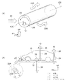
図1(A)に示すように、車幅方向に延設された円柱形状のロータ12は図示しない駆動手段によって軸12Cを中心として矢印20のように回転可能に支持されている。図1(B)に示すように車体10には複数のロータ12が設けられ、それぞれ矢印20の方向に回転可能とされている。
As shown in FIG. 1A, the
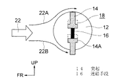
図2に示すようにロータ12の内部に設けられた空隙18には、一対の突起14がロータ12の径中心に対して対称となるように一対設けられている。一対の突起14はロータ12の径方向中心部分において、互いに連結手段16で連結され、一方の突起14のみがロータ12の表面から突出可能とされている。
As shown in FIG. 2, a pair of
突起14は車体下側に位置するときロータ12から自重で車体下側に突出し、ロータ12が回転して車体上側に移動すると自重でロータ12内部の空隙18へ収容される。
When the
またロータ12の外周面は平滑な面に限定されず、微細な穴などの凸凹や歯車状の凹凸、あるいは整流効果のある溝やフィンなどが設けられていてもよい。
The outer peripheral surface of the
<作用効果>
次に本発明の第1実施形態の作用および効果について説明する。
<Effect>
Next, the operation and effect of the first embodiment of the present invention will be described.
図1(A)に示すように、走行中はロータ12には車体前方より走行風22が吹き付けている。ロータ12が矢印20のように回転していると、その表面では上下に別れた走行風22はそれぞれ車体上方では走行風22A、車体下方では走行風22Bのようにロータ12の上下を通過する。
As shown in FIG. 1A, traveling
このとき走行風22Aは、ロータ12の回転(矢印20)が走行風22Aの風向と逆であるため、これに伴う表面摩擦によって流速が低下する。逆に走行風22Bは矢印20のようなロータ12の回転に伴い、ロータ12の表面が風向と同方向に回転移動するため、流速が高くなる。
At this time, since the
このためロータ12の車体上側では気圧が高く、車体下側では気圧が低くなる。これによりロータ12に対しては、車体下側に吸引される方向に力が働く(マグナス効果)。図1(B)に示すように車体10に設けられたロータ12が矢印20の方向に回転した場合は、上記の効果により各々のロータ12に対して矢印のようにダウンフォース24が発生し、車体10全体を車体下側に押し付ける方向に力が働く。
For this reason, the atmospheric pressure is high on the upper side of the vehicle body of the
これにより車体10はエアダムやウイングなどの空力的付加物によって発生する空力効果に加えて、ロータ12で発生するダウンフォース24によっても安定して接地性を得ることができ、より安定した走行が可能となる。
Thereby, in addition to the aerodynamic effect generated by an aerodynamic addition such as an air dam or wing, the
また車体10の車体前方端に設けられたロータ12の場合は一点鎖線で拡大図を示したように、車体10との間を流れる走行風22が斜め上前方から斜め下後方に流れるようにすれば、車体前方へのベクトルを含むダウンフォース24’とすることができ、走行性能および経済性の改良が期待できる。
Further, in the case of the
図2に示すようにロータ12に設けられた一対の突起14は車体下側に位置するときロータ12から自重で車体下側に突出して、前方からの走行風22Bを受ける。このためロータ12は矢印20の方向へ回転するように力を受ける。
As shown in FIG. 2, when the pair of
さらにロータ12の回転によって、走行風22Bを受けた突起14が車体上側に移動すると、突起14は自重でロータ12内部の空隙18へ収容される。このため車体上側では、突起14は走行風22Aを受けることはなく、常にロータ12の車体下側でのみ突起14は走行風22Aを受けるので、他に駆動手段を設ずとも走行風22Aによって矢印20方向に回り続けることができる。
Further, when the
<第2実施形態>
本発明の第2実施形態に係る車両用空力制御装置の詳細を図3に従って説明する。
<Second Embodiment>
Details of the aerodynamic control device for a vehicle according to the second embodiment of the present invention will be described with reference to FIG.
図3には、本発明が適用された第1実施形態に係る車両用空力制御装置が示されている。 FIG. 3 shows a vehicle aerodynamic control device according to the first embodiment to which the present invention is applied.
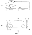
図3(B)に示すように、車幅方向に延設された円柱形状のロータ12は図示しない駆動手段によって回転可能に支持されている点は第1実施形態と同様である。本実施形態においては、ロータ12は車幅方向中央で左右に2分割され、ロータ12Rとロータ12Lとしてそれぞれ独立して駆動可能とされている。
As shown in FIG. 3B, the
図3(C)に示すように、前輪11Fに舵角を与えて走行中の車体10を旋回させる操舵装置19には伝達手段29が設けられ、ロータ12Rとロータ12Lとにそれぞれ制動をかける制動手段27Rと制動手段27Lとに操舵装置19から舵角および操舵方向に関する情報が伝達される。
As shown in FIG. 3C, a
制動手段27と伝達手段29とは例えばワイヤブレーキや油圧アクチュエータのように機械的な接続でもよく、あるいは図示しない制御手段を解して伝達手段29が伝達する舵角および操舵方向の情報より電磁ブレーキ等を操作する、電気的な接続方法であってもよい。この場合の伝達手段29はポジションセンサ等を使用することができる。 The braking means 27 and the transmission means 29 may be mechanically connected, such as a wire brake or a hydraulic actuator, or an electromagnetic brake based on information on the steering angle and steering direction transmitted by the transmission means 29 via a control means (not shown). An electrical connection method may be used. In this case, the transmission means 29 can use a position sensor or the like.
制動手段27は、伝達手段29による操舵装置19の舵角および操舵方向の情報から、操舵装置19が舵を切った方向のロータ12(右へ操舵すれば車体右側のロータ12R)はそのまま作動させ、他方のロータ12(右へ操舵すれば車体左側のロータ12L)は減速あるいは停止させるように制御される構成となっている。
From the information on the steering angle and steering direction of the
<作用効果>
次に本発明の第2実施形態の作用および効果について説明する。
<Effect>
Next, the operation and effect of the second embodiment of the present invention will be described.
図3(B)に示すように、旋回中の車体10には旋回する方向に応じて車体10を左右に傾かせる、いわゆるロールが発生する。図3(B)のように右に旋回すれば矢印25のように車体10をロールさせる力が働き、このロールが大きくなれば走行安定性に影響を与える虞がある。
As shown in FIG. 3 (B), a so-called roll is generated in the
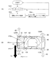
本実施形態においては図3(A)にフローチャートで示すように、操舵装置19が作動し、車体10が旋回を開始すると、旋回方向アウト側の制動手段27のみが作動し、ロータ12を停止または減速させる。
In the present embodiment, as shown in the flowchart in FIG. 3A, when the
図3(A)のフローチャートを参照して本実施例の作用を説明する。まずステップ100では図示しない舵角センサが、車体が操舵状態であるか否かの判定を行う。操舵状態であると判定された場合はステップ102へ移行する。
The operation of the present embodiment will be described with reference to the flowchart of FIG. First, at
ステップ102では、旋回方向が右旋回であるか左旋回であるかを舵角センサからの舵角情報に基づいて判定する。結果が左旋回であればステップ104へ、右旋回であればステップ106へ移行する。
In
ステップ104では、車体が左旋回していると判断され、右側のロータ12Rのみ回転駆動され、左側のロータ12Lには制動手段27Lが作動することで制動がかかる。
In
ステップ106では、車体が右旋回していると判断され、左側のロータ12Lのみ回転駆動され、右側のロータ12Rには制動手段27Rが作動することで制動がかかる。図示しない舵角センサからの舵角情報が直進を示すまで、ステップ100に戻って上述の処理が繰り返される。
In
上記のようにしてロータ12が駆動制御された結果、図3(B)および図3(C)に示すように車体10が右に旋回すれば旋回方向アウト側、つまり左側の制動手段27Lのみが作動し、左側のロータ12Lが停止または減速する。
As a result of the drive control of the
これにより左側のロータ12Lではダウンフォースは発生しないか、または効果が弱くなり、且つ右側のロータ12Rで発生するダウンフォース24が車体10に働くため、図3(B)に矢印25で示す車体10のロールを打ち消す方向にダウンフォース24を利用することができる。
As a result, no downforce is generated in the
この構成とすることで、図3(B)に示すように旋回中の車体10に対してイン側のロータ12のみを作動させ、車体10のロールを抑えることで、より安定した旋回を行うことができる。
With this configuration, as shown in FIG. 3B, only the in-
<第3実施形態>
本発明の第3実施形態に係る車両用空力制御装置の詳細を図4に従って説明する。
<Third Embodiment>
Details of the vehicle aerodynamic control device according to the third embodiment of the present invention will be described with reference to FIG.
図4には、本発明が適用された第3実施形態に係る車両用空力制御装置が示されている。図4(B)に示すように、車体10には車幅方向に延設された円柱形状のロータ12が車体前後に少なくとも一対設けられている点は第1実施形態と同様である。
FIG. 4 shows an aerodynamic control device for a vehicle according to a third embodiment to which the present invention is applied. As shown in FIG. 4B, the
ロータ12はそれぞれ図示しない駆動手段によって回転軸を中心として矢印20のように回転可能に支持され、また図示しない制御手段によって回転速度が制御されている。車体10には図示しないブレーキ(制動手段)が設けられ、ブレーキ作動の有無はデータとして図示しない制御手段に送られる。
Each of the
<作用効果>
次に本発明の第3実施形態の作用および効果について説明する。
<Effect>
Next, the operation and effect of the third embodiment of the present invention will be described.
図4(A)にフローチャートで示すように、図示しないブレーキが作動すると図示しないブレーキセンサにより検知された制動操作が制御手段にデータとして送られ、図示しない駆動手段を制御してロータ12の回転速度を増加させる。
As shown in the flowchart of FIG. 4A, when a brake (not shown) is operated, a braking operation detected by a brake sensor (not shown) is sent as data to the control means, and the rotational speed of the
図4(A)のフローチャートを参照して本実施例の作用を説明する。まずステップ200では図示しないブレーキセンサが、車体が制動状態であるか否かの判定を行う。制動状態であると判定された場合はステップ202へ移行する。
The operation of the present embodiment will be described with reference to the flowchart of FIG. First, in
ステップ202では、図示しない制御手段に対して回転数を増加させる命令を発する。これによりロータ12の回転数が増加し、ステップ204に移行する。
In
ステップ204では、ロータ12の回転数が増加したことによりダウンフォース24が増加し、車体10のリフトを抑制する。図示しないブレーキセンサからの情報がブレーキ開放を示すまで、ステップ200に戻って上述の処理が繰り返される。
In
この構成とすることで、図4(B)に示すように車体前後に設けられたロータ12がより高速で回転し、発生するダウンフォース24も増加する。これにより制動中の車体10を車体下方により強く押し付けられ、より安定した制動を行うことができる。
With this configuration, as shown in FIG. 4B, the
<第4実施形態>
本発明の第4実施形態に係る車両用空力制御装置の詳細を図5に従って説明する。
<Fourth embodiment>
Details of the vehicle aerodynamic control device according to the fourth embodiment of the present invention will be described with reference to FIG.
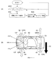
図5には、本発明が適用された第4実施形態に係る車両用空力制御装置が示されている。図5(B)、図5(C)に示すように、車体10には車幅方向に延設された円柱形状のロータ12が車体前後に少なくとも一対設けられている点は第1実施形態と同様である。
FIG. 5 shows a vehicle aerodynamic control device according to a fourth embodiment to which the present invention is applied. As shown in FIGS. 5B and 5C, the
ロータ12はそれぞれ図示しない駆動手段によって回転軸を中心として矢印20のように回転可能に支持され、また図示しない制御手段によって回転速度および回転方向が制御されている。車体10の車体前後端近傍には図示しない車高センサが設けられ、車体前後の車高に差があるか否か、あればその差がデータとして図示しない制御手段に送られる。
The
<作用効果>
次に本発明の第4実施形態の作用および効果について説明する。
<Effect>
Next, the operation and effect of the fourth embodiment of the present invention will be described.
図5(A)にフローチャートで示すように、図示しない車高センサが車体前後で車高に差を検知した場合、図示しない制御手段にデータとして送られ、図示しない駆動手段を制御して車体前後に設けられたロータ12の回転速度をそれぞれ増加あるいは減少、または逆回転させる。
As shown in the flowchart of FIG. 5A, when a vehicle height sensor (not shown) detects a difference in vehicle height before and after the vehicle body, it is sent as data to a control means (not shown) and controls the drive means (not shown) to control the vehicle front and back. The rotational speed of the
図5(A)のフローチャートを参照して本実施例の作用を説明する。まずステップ300では図示しない車高センサが、車体がピッチングを起こしている状態であるか否かの判定を行う。ピッチングを起こしている状態であると判定された場合はステップ302へ移行する。
The operation of the present embodiment will be described with reference to the flowchart of FIG. First, at
ステップ302では、図示しない車高センサが車体10の前が高い、スクォート状態であるか否かを判定する。スクォート状態であると判定された場合はステップ304へ、逆にノーズダイブ状態であると判定された場合はステップ306へ移行する。
In
ステップ304では、図5(B)に示すように、車体前方のロータ12Fの回転数を増加させ、車体後方のロータ12Rを矢印21のように逆回転させる。ロータ12Fの回転数を増加したことにより車体前方ではダウンフォース24が増加し、またロータ12Rが逆回転することにより車体後方では揚力26が発生する。これにより車体10のスクォートを抑制する。
In
ステップ306では、図5(C)に示すように、車体後方のロータ12Rの回転数を増加させ、車体前方のロータ12Fを矢印21のように逆回転させる。ロータ12Rの回転数を増加したことにより車体後方ではダウンフォース24が増加し、またロータ12Fが逆回転することにより車体前方では揚力26が発生する。これにより車体10のノーズダイブを抑制する。図示しない車高センサからの情報が車体前後で車高に差なしを示すまで、ステップ300に戻って上述の処理が繰り返される。
In
この構成とすることで、図5(B)、図5(C)に示すように車体前後に設けられたロータ12F、ロータ12Rがそれぞれより高速で回転し、あるいは逆回転することで発生するダウンフォース24を増加させ、あるいは揚力26を発生させる。
With this configuration, as shown in FIGS. 5B and 5C, the
これにより上記のスクォート、ノーズダイブ状態に加えて車体10の前後が上下方向に振れる、いわゆるピッチングを解消する方向にダウンフォース24と揚力26を発生させることができるので、より安定した走行を行うことができる。
As a result, in addition to the above-described squat and nose dive state, the front and rear of the
<第5実施形態>
本発明の第5実施形態に係る車両用空力制御装置の詳細を図6および図7に従って説明する。図6および図7には、本発明が適用された第5実施形態に係る車両用空力制御装置が示されている。
<Fifth Embodiment>
Details of the aerodynamic control device for a vehicle according to the fifth embodiment of the present invention will be described with reference to FIGS. 6 and 7 show a vehicle aerodynamic control device according to a fifth embodiment to which the present invention is applied.
図6(B)、図7(B)に示すように、車体10には車体上下方向に延設された円柱形状のロータ112が少なくとも車体前または後端近傍において車幅方向両端に一対、より望ましくは車体前後端近傍に一対づつ設けられている。
As shown in FIGS. 6 (B) and 7 (B), the
ロータ112はそれぞれ図示しない駆動手段によって回転軸を中心として矢印30または矢印32のように回転可能に支持され、また図示しない制御手段によって回転速度および回転方向が制御されている。車体10には図示しない舵角センサ、および車体前後端における左右方向の加速度を検知する加速度センサが設けられ、運転者が操舵した際の舵角、および車体10の前後端における左右方向のモーメントを検知し、データとして図示しない制御手段に送る。
Each of the rotors 112 is supported by a driving means (not shown) so as to be rotatable around an axis of rotation as indicated by an
<作用効果>
次に本発明の第5実施形態の作用および効果について説明する。
<Effect>
Next, operations and effects of the fifth exemplary embodiment of the present invention will be described.
図6(A)にフローチャートで示すように、旋回中の車体10において図示しない舵角センサが検出した前輪11Fの方向(=進みたい方向FR1)に対して、図示しない加速度センサが車体後端が矢印50のようにアウト側へ滑り始め、車体10が方向FR2へ向かう、いわゆるオーバーステアの状態であると制御手段が判断した場合、ロータ112をそれぞれ動作させ、オーバーステア状態のモーメントを打ち消す方向(矢印60)に車体前後端にモーメントを発生させる。
As shown in the flowchart in FIG. 6A, an acceleration sensor (not shown) is installed at the rear end of the
図6(A)のフローチャートを参照して本実施例の作用を説明する。まずステップ400では図示しない舵角センサおよび加速度センサが、車体がオーバーステアであるか否かの判定を行う。オーバーステアであると判定された場合はステップ402へ移行する。
The operation of the present embodiment will be described with reference to the flowchart of FIG. First, at
ステップ402では、図6(B)に示すように、図示しない制御手段が車体前方のロータ112FRおよびロータ112FLは矢印30方向に回転させるように、また車体後端のロータ112RRおよびロータ112RLは矢印32方向に回転させるように図示しない回転手段に指示を出し、ステップ404に移行する。
In
ステップ404では、車体前方のロータ112FRおよびロータ112FLが矢印30方向に回転することにより矢印40のように車体前端をアウト側へ向けるモーメントを発生させ、車体後端のロータ112RRおよびロータ112RLは矢印32方向に回転することにより、矢印42のように車体後端をイン側へ向けるモーメントを発生させる。これにより車体10をオーバーステア方向に回転させようとするモーメントを打ち消し、(矢印60)安定した旋回を行うことができる。
In
図示しない舵角センサおよび加速度センサからの情報が、オーバーステア状態の解消を示すまで、ステップ400に戻って上述の処理が繰り返される。 Until the information from the steering angle sensor and the acceleration sensor (not shown) indicates the cancellation of the oversteer state, the process returns to step 400 and the above processing is repeated.
図7(A)のフローチャートを参照して本実施例の作用を説明する。まずステップ500では図示しない舵角センサおよび加速度センサが、車体がアンダーステアであるか否かの判定を行う。アンダーステアであると判定された場合はステップ502へ移行する。
The operation of the present embodiment will be described with reference to the flowchart of FIG. First, at
ステップ502では、図7(B)に示すように、図示しない制御手段が車体前方のロータ112FRおよびロータ112FLは矢印32方向に回転させるように、また車体後端のロータ112RRおよびロータ112RLは矢印30方向に回転させるように図示しない回転手段に指示を出し、ステップ504に移行する。
In
ステップ504では、車体前方のロータ112FRおよびロータ112FLが矢印32方向に回転することにより矢印42のように車体前端をイン側へ向けるモーメントを発生させ、車体後端のロータ112RRおよびロータ112RLは矢印30方向に回転することにより、矢印40のように車体後端をアウト側へ向けるモーメントを発生させる。これにより車体10をアンダーステア方向に回転させようとするモーメントを打ち消し、(矢印62)安定した旋回を行うことができる。
In
図示しない舵角センサおよび加速度センサからの情報が、アンダーステア状態の解消を示すまで、ステップ500に戻って上述の処理が繰り返される。 Until the information from the steering angle sensor and the acceleration sensor (not shown) indicates the cancellation of the understeer state, the process returns to step 500 and the above-described processing is repeated.
上記の実施形態では車体前後方向に一対づつのロータ112が設けられているが、これに限定せず車体前端または車体後端に左右一対のみ設けられたロータ112を駆動することにより、車体前端または車体後端でオーバーステアあるいはアンダーステアを解消する方向にモーメントを発生させる構成とされていてもよい。 In the above-described embodiment, a pair of rotors 112 is provided in the vehicle longitudinal direction. However, the present invention is not limited to this, and by driving the rotor 112 provided only in a pair of left and right at the vehicle front end or vehicle rear end, A configuration may be adopted in which a moment is generated in a direction to eliminate oversteer or understeer at the rear end of the vehicle body.
<第6実施形態>
本発明の第6実施形態に係る車両用空力制御装置の詳細を図8に従って説明する。図8には、本発明が適用された第6実施形態に係る車両用空力制御装置が示されている。
<Sixth Embodiment>
Details of the vehicle aerodynamic control device according to the sixth embodiment of the present invention will be described with reference to FIG. FIG. 8 shows an aerodynamic control device for a vehicle according to a sixth embodiment to which the present invention is applied.
図8(B)に示すように、車体10には車体上下方向に延設された円柱形状のロータ112が少なくとも車体前または後端近傍において車幅方向両端に一対、より望ましくは車体前後端近傍に一対づつ設けられている点は第5実施形態と同様である。
As shown in FIG. 8B, the
ロータ112はそれぞれ図示しない駆動手段によって回転軸を中心として矢印30または矢印32のように回転可能に支持され、また図示しない制御手段によって回転速度および回転方向が制御されている。車体10には図示しない舵角センサ、車輪速度センサ、加速度センサ、車体の進行方向を検知するヨーレートセンサなどが設けられ、運転者が操舵した際の舵角に応じた前輪11Fの方向FR1と車体10が実際に進行する方向FR2とのなす角度であるスリップアングルθ1を検知し、データとして図示しない制御手段に送る。
Each of the rotors 112 is supported by a driving means (not shown) so as to be rotatable around an axis of rotation as indicated by an
<作用効果>
次に本発明の第6実施形態の作用および効果について説明する。
<Effect>
Next, operations and effects of the sixth embodiment of the present invention will be described.
図8(A)にフローチャートで示すように走行中の車体10において、図示しない各種センサが検出した前輪11Fの方向(=進みたい方向FR1)と車体10が実際に進行する方向FR2とのなす角度であるスリップアングルθ1が所定の値よりも大きいと図示しない制御手段が判断した場合、ロータ112を作動させてスリップアングルθ1を縮小させる。
As shown in the flowchart in FIG. 8A, in the traveling
図8(A)のフローチャートを参照して本実施例の作用を説明する。まずステップ600では図示しない舵角センサ、加速度センサ、ヨーレートセンサが、図7(B)に示す車体のスリップアングルθ1が所定の閾値以上であるか否かの判定を行う。閾値以上であると判定された場合はステップ602へ移行する。
The operation of the present embodiment will be described with reference to the flowchart of FIG. First, at
ステップ602では、図7(C)に示すように、図示しない制御手段が車体前方のロータ12FRおよびロータ12FLは矢印30方向に回転させるように、また車体後端のロータ12RRおよびロータ12RLは矢印32方向に回転させるように図示しない回転手段に指示を出し、ステップ604に移行する。
In
ステップ604では、車体前方のロータ12FRおよびロータ12FLが矢印30方向に回転することにより矢印40のように車体前端をFR2側へ向けるモーメントを発生させ、車体後端のロータ12RRおよびロータ12RLは矢印32方向に回転することにより、矢印42のように車体後端をFR2と逆側へ向けるモーメントを発生させる。これにより車体10のスリップアングルθ1をθ2のように減少させ、安定した走行を行うことができる。
In
図示しない舵角センサ、加速度センサおよびヨーレートセンサからの情報が、スリップアングルθ1が所定の閾値以下を示すまで、ステップ600に戻って上述の処理が繰り返される。 Until the information from the steering angle sensor, the acceleration sensor, and the yaw rate sensor (not shown) indicates that the slip angle θ1 is equal to or less than the predetermined threshold value, the process returns to step 600 and the above-described processing is repeated.
上記の処理により車体10が実際に進行する方向は方向FR3となり、スリップアングルθ1はスリップアングルθ2のように縮小され、前輪11Fの方向(=進みたい方向FR1)と車体10が実際に進行する方向FR3とのズレは小さくなるため、より自然な感覚で安定した走行を行うことができる。
The direction in which the
<他の実施形態>
本発明の他の実施形態の詳細を図9、図10、図11に従って説明する。
<Other embodiments>
Details of another embodiment of the present invention will be described with reference to FIGS.
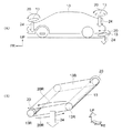
図9には本発明が適用された第7実施形態に係る車両用空力制御装置が示されている。図9(A)に示すように、車体10にはロータ12に代えて、車幅方向に複数延設されたシャフト13Rに巻き掛けられ車体前後方向に駆動されるベルト13が設けられている。
FIG. 9 shows an aerodynamic control device for a vehicle according to a seventh embodiment to which the present invention is applied. As shown in FIG. 9A, instead of the
図9(B)に示すように、ベルト13は車幅方向に延設され図示しない駆動手段で回転駆動される複数のシャフト13Rに巻き掛けられ、矢印20Rのように車体前後方向に駆動される。あるいはシャフト13Rは従動ローラとされ、ベルト13の外周面をプーリーなどで駆動する方式とされていてもよい。
As shown in FIG. 9B, the
あるいはシャフト13Rが車体上下方向に延設され、複数のシャフト13Rにベルト13が巻き掛けられる構成であってもよい。
Alternatively, the
この構成とすることで、シャフト13Rが矢印20のように回転するとき、ベルト13は矢印20Rのように搬送駆動されるので、ベルト13の外周面13Bと走行風との間でマグナス効果が発生し、車体10に対してダウンフォース24を発生させることができる。あるいはシャフト13Rを車体上下方向に延設することで、第5実施形態または第6実施形態と同等の効果を得ることができる。この構成ではロータ12を用いる構成に比較して、外周面13Bの面積をロータ12の表面積よりも大きく取りやすいため、より効果の高い空力性能を期待できる。また曲面に沿わせるなど、形状の自由度も大きくすることができる。
With this configuration, when the
図10には本発明が適用された第8実施形態に係る車両用空力制御装置が示されている。図10に示すように、ロータ12(あるいはロータ112)の車体前方、車体後方の少なくとも一方に整流部材15が設けられ、ロータ12(あるいはロータ112)を車体前方または車体後方からの正面視でカバーしている。
FIG. 10 shows an aerodynamic control device for a vehicle according to an eighth embodiment to which the present invention is applied. As shown in FIG. 10, a rectifying
この構成とすることで、ロータ12(あるいはロータ112)において空力的効果の発生する車体上下方向(または車幅方向)の面はそのまま走行風22に接触する一方、車体前方に設けられた整流部材15Fは走行風22に対する空気抵抗を低減し、車体後方に設けられた整流部材15Rはロータ12(あるいはロータ112)の車体後方で発生する伴流の影響を小さく抑えることができる。
With this configuration, the vehicle body vertical direction (or vehicle width direction) surface where the aerodynamic effect is generated in the rotor 12 (or the rotor 112) is in direct contact with the traveling
これにより整流部材15F、15Rはそれぞれロータ12(あるいはロータ112)の空気抵抗を低減させることができ、走行に要するエネルギーの節約および風切り音の低減などの効果を得ることができる。 Thus, the rectifying members 15F and 15R can reduce the air resistance of the rotor 12 (or the rotor 112), respectively, and can obtain effects such as saving energy required for traveling and reducing wind noise.
また、フロントエアダムやリアスポイラーなど既に車体意匠の一部となっている空力部材にロータ12(あるいはロータ112)を内蔵させることができるので、より車体10の意匠に高い自由度と、より高い空力性能をもたせることができる。
Further, since the rotor 12 (or the rotor 112) can be incorporated in an aerodynamic member that is already part of the vehicle body design, such as a front air dam or a rear spoiler, the design of the
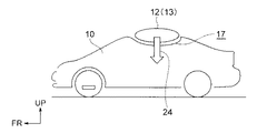
図11には本発明が適用された第9実施形態に係る車両用空力制御装置が示されている。図11に示すように、車体10にはロータ12(あるいはベルト13)の形状に合わせた凹部17が設けられ、ロータ12(あるいはベルト13)は凹部17に嵌り込むことで、車体10の車体上下方向(あるいは車幅方向、車体前後方向も含む)外側にロータ12(あるいはベルト13)が突出する量を低減させる構成とされている。
FIG. 11 shows an aerodynamic control device for a vehicle according to a ninth embodiment to which the present invention is applied. As shown in FIG. 11, the
この構成とすることで、車体10から外側へロータ12が突出する量を少なくすることができ、意匠や車体寸法の点で自由度を高めることができる。
By setting it as this structure, the quantity which the
以上、実施形態を挙げて本発明の実施の形態を説明したが、これらの実施形態は一例であり、要旨を逸脱しない範囲内で種々変更して実施できる。また、本発明の権利範囲がこれらの実施形態に限定されず、本発明の要旨を逸脱しない範囲において種々なる態様で実施し得ることは言うまでもない。 The embodiments of the present invention have been described above with reference to the embodiments. However, these embodiments are merely examples, and various modifications can be made without departing from the scope of the invention. Further, it goes without saying that the scope of rights of the present invention is not limited to these embodiments and can be implemented in various modes without departing from the gist of the present invention.
すなわち、上記実施形態では車体10の外部表面を例に挙げたが、これに限定せず他の構成であっても本発明を適用することができる。例えばエアインテークからのエンジン冷却風流路やブレーキダクト内面などの空力に関しても本発明を適用することができる。
That is, in the above embodiment, the outer surface of the
10 車体
11F 前輪
12 ロータ
12C 軸
13R シャフト
13 ベルト
14 突起
15 整流部材
16 連結手段
17 凹部
18 空隙
22A 走行風
22B 走行風
24 ダウンフォース
26 揚力
112 ロータ
DESCRIPTION OF
Claims (6)
前記スポイラ内に、半径方向に移動可能に収容されると共に、対称形に複数個配置され、自重により径方向一方側に突出可能に支持された突出部と、を備えたことを特徴とする車両用空力制御装置。 A columnar spoiler that is arranged with the vehicle width direction as the axial direction and is supported rotatably around the axis;
A vehicle comprising: a plurality of symmetrically arranged protrusions that are accommodated in the spoiler so as to be movable in a radial direction, and that are supported so as to be able to protrude in one radial direction by their own weight. Aerodynamic control device.
前記左右一対の円柱形状のスポイラまたは前記左右一対の無端ベルト形状のスポイラにそれぞれ設けられ、各々独立して回転駆動させる回転手段と、
操舵角を検知し、前記回転手段を制御する制御手段と、
を備え、
前記制御手段は操舵角に基づいて操舵方向側の前記円柱形状のスポイラまたは前記無端ベルト形状のスポイラがダウンフォースを発生させるように回転駆動され、操舵方向反対側の前記円柱形状のスポイラまたは前記無端ベルト形状のスポイラは停止または逆回転させることを特徴とする車両用空力制御装置。 A pair of left and right columnar spoilers arranged with the vehicle width direction as an axial direction and supported so as to be rotatable around the axis, or a pair of left and right endless belts wound around a plurality of rotation shafts extending in the vehicle width direction Shape spoiler,
Rotating means provided on each of the pair of left and right columnar spoilers or the pair of left and right endless belt spoilers, each of which independently rotates.
Control means for detecting the steering angle and controlling the rotation means;
With
The control means is driven to rotate so that the columnar spoiler on the steering direction side or the endless belt-shaped spoiler generates downforce based on the steering angle, and the columnar spoiler on the opposite side in the steering direction or the endless An aerodynamic control device for a vehicle, wherein the belt-shaped spoiler is stopped or reversely rotated.
前記円柱形状のスポイラまたは前記無端ベルト形状のスポイラを回転駆動させる回転手段と、
制動操作を検知し、前記回転手段を制御する制御手段と、
を備え、
前記制御手段は制動操作に基づいてダウンフォースを発生させるように前記円柱形状のスポイラまたは前記無端ベルト形状のスポイラを駆動することを特徴とする車両用空力制御装置。 A columnar spoiler which is arranged with the vehicle width direction as an axial direction and is supported so as to be rotatable around the axis line, or an endless belt-shaped spoiler wound around a plurality of rotation shafts extending in the vehicle width direction;
Rotating means for rotationally driving the cylindrical spoiler or the endless belt-shaped spoiler;
Control means for detecting a braking operation and controlling the rotating means;
With
The vehicle aerodynamic control device, wherein the control means drives the columnar spoiler or the endless belt spoiler so as to generate a downforce based on a braking operation.
前記円柱形状のスポイラまたは前記無端ベルト形状のスポイラを回転駆動させる回転手段と、
車体のピッチングを検知し、前記回転手段を制御する制御手段と、
を備え、
前記制御手段は車体が前下がりの時には車体後方でダウンフォースを発生させるように車体後方の前記円柱形状のスポイラまたは前記無端ベルト形状のスポイラを駆動し、
車体が前上がりの時には車体前方でダウンフォースを発生させるように車体前方の前記円柱形状のスポイラまたは前記無端ベルト形状のスポイラを駆動することを特徴とする車両用空力制御装置。 At least one pair is provided on the front and rear of the vehicle body, arranged in the vehicle width direction as an axial direction, and wound around a columnar spoiler supported rotatably around the axis or a plurality of rotation shafts extending in the vehicle width direction An endless belt-shaped spoiler,
Rotating means for rotationally driving the cylindrical spoiler or the endless belt-shaped spoiler;
Control means for detecting pitching of the vehicle body and controlling the rotating means;
With
The control means drives the columnar spoiler or the endless belt-shaped spoiler at the rear of the vehicle body so as to generate a downforce at the rear of the vehicle body when the vehicle body is lowered forward,
An aerodynamic control device for a vehicle that drives the columnar spoiler or the endless belt spoiler in front of the vehicle body so as to generate a downforce in front of the vehicle body when the vehicle body rises forward.
前記円柱形状のスポイラまたは前記無端ベルト形状のスポイラを回転駆動させる回転手段と、
前記回転手段を制御する制御手段と、
操舵角度を検知し、前記制御手段に伝達する舵角センサと、
車体前後端の横Gを検知し、前記制御手段に伝達する少なくとも前後一対の横Gセンサと、を備え、
前記制御手段は旋回中に前記舵角センサおよび前記横Gセンサからの情報に基づきオーバーステアあるいはアンダーステアを検知すると、オーバーステア時には車体前方をアウト側へ、車体後方をイン側へ付勢するモーメントを発生させ、アンダーステア時には車体前方をイン側へ、車体後方をアウト側へ付勢するモーメントを発生させるように前記回転手段を制御することを特徴とする車両用空力制御装置。 At least one pair in the vehicle width direction is arranged with the vertical direction of the vehicle body as the axial direction, and is wound around a cylindrical spoiler supported so as to be rotatable around the axis or a plurality of rotation shafts extending in the vertical direction of the vehicle body An endless belt-shaped spoiler,
Rotating means for rotationally driving the cylindrical spoiler or the endless belt-shaped spoiler;
Control means for controlling the rotating means;
A steering angle sensor for detecting a steering angle and transmitting it to the control means;
A pair of lateral G sensors for detecting the lateral G at the front and rear ends of the vehicle body and transmitting the lateral G to the control means;
When the control means detects oversteer or understeer based on information from the rudder angle sensor and the lateral G sensor during turning, a moment for urging the front of the vehicle body to the out side and the rear of the vehicle body to the in side during oversteering. An aerodynamic control device for a vehicle, wherein the rotating means is controlled so as to generate a moment that urges the front of the vehicle body to the in side and the rear of the vehicle body to the out side when understeering.
前記円柱形状のスポイラまたは前記無端ベルト形状のスポイラを回転駆動させる回転手段と、
前記回転手段を制御する制御手段と、
路面に対する車体のスリップアングルを検出し、前記制御手段に伝達するスリップアングルセンサと、を備え、
前記制御手段は前記スリップアングルが所定の角度より大きいとき、前記スリップアングルを解消するモーメントを発生させるように前記回転手段を制御することを特徴とする車両用空力制御装置。 At least a pair in the vehicle width direction is arranged with the vertical direction of the vehicle body as the axial direction, and is wound around a cylindrical spoiler supported rotatably around the axis line or a plurality of rotation shafts extending in the vertical direction of the vehicle body An endless belt-shaped spoiler,
Rotating means for rotationally driving the cylindrical spoiler or the endless belt-shaped spoiler;
Control means for controlling the rotating means;
A slip angle sensor that detects the slip angle of the vehicle body relative to the road surface and transmits the detected slip angle to the control means,
The vehicle aerodynamic control device according to claim 1, wherein when the slip angle is larger than a predetermined angle, the control means controls the rotation means so as to generate a moment for eliminating the slip angle.
Priority Applications (1)
| Application Number | Priority Date | Filing Date | Title |
|---|---|---|---|
| JP2008325936A JP2010143530A (en) | 2008-12-22 | 2008-12-22 | Aerodynamic controller for vehicle |
Applications Claiming Priority (1)
| Application Number | Priority Date | Filing Date | Title |
|---|---|---|---|
| JP2008325936A JP2010143530A (en) | 2008-12-22 | 2008-12-22 | Aerodynamic controller for vehicle |
Publications (1)
| Publication Number | Publication Date |
|---|---|
| JP2010143530A true JP2010143530A (en) | 2010-07-01 |
Family
ID=42564396
Family Applications (1)
| Application Number | Title | Priority Date | Filing Date |
|---|---|---|---|
| JP2008325936A Pending JP2010143530A (en) | 2008-12-22 | 2008-12-22 | Aerodynamic controller for vehicle |
Country Status (1)
| Country | Link |
|---|---|
| JP (1) | JP2010143530A (en) |
Cited By (9)
| Publication number | Priority date | Publication date | Assignee | Title |
|---|---|---|---|---|
| JP2013193596A (en) * | 2012-03-21 | 2013-09-30 | Hitachi Automotive Systems Ltd | Vehicle control device |
| JP2014136463A (en) * | 2013-01-15 | 2014-07-28 | Toyota Motor Corp | Aerodynamic control device for vehicle or movable body and vehicle or movable body including aerodynamic control device |
| FR3063270A1 (en) * | 2017-02-24 | 2018-08-31 | Peugeot Citroen Automobiles Sa | AERODYNAMIC FLOORING APPARATUS OF A MOTOR VEHICLE COMPRISING A HORIZONTAL AIR DEFLECTOR HAVING A ROTARY CYLINDER. |
| KR101984130B1 (en) * | 2017-11-28 | 2019-05-30 | 공주대학교 산학협력단 | Device for Decreasing a Resistance in Railroad vehicle using Air Peeling |
| US10443564B2 (en) | 2015-07-01 | 2019-10-15 | Challenergy Inc. | Magnus type thrust generating device |
| CN111216813A (en) * | 2020-02-07 | 2020-06-02 | 石家庄铁道大学 | Racing car tail fin and racing car |
| CN114162228A (en) * | 2021-11-16 | 2022-03-11 | 上汽大众汽车有限公司 | Active lower spoiler system for aerodynamic control of vehicle and vehicle |
| US11447193B2 (en) * | 2019-06-10 | 2022-09-20 | GM Global Technology Operations LLC | Control of vehicle aerodynamic force for hydroplaning mitigation |
| JP2023514004A (en) * | 2019-12-12 | 2023-04-05 | マグヌス フォース エルエルシー | Auxiliary propulsion system for vehicles |
-
2008
- 2008-12-22 JP JP2008325936A patent/JP2010143530A/en active Pending
Cited By (10)
| Publication number | Priority date | Publication date | Assignee | Title |
|---|---|---|---|---|
| JP2013193596A (en) * | 2012-03-21 | 2013-09-30 | Hitachi Automotive Systems Ltd | Vehicle control device |
| JP2014136463A (en) * | 2013-01-15 | 2014-07-28 | Toyota Motor Corp | Aerodynamic control device for vehicle or movable body and vehicle or movable body including aerodynamic control device |
| US10443564B2 (en) | 2015-07-01 | 2019-10-15 | Challenergy Inc. | Magnus type thrust generating device |
| FR3063270A1 (en) * | 2017-02-24 | 2018-08-31 | Peugeot Citroen Automobiles Sa | AERODYNAMIC FLOORING APPARATUS OF A MOTOR VEHICLE COMPRISING A HORIZONTAL AIR DEFLECTOR HAVING A ROTARY CYLINDER. |
| KR101984130B1 (en) * | 2017-11-28 | 2019-05-30 | 공주대학교 산학협력단 | Device for Decreasing a Resistance in Railroad vehicle using Air Peeling |
| US11447193B2 (en) * | 2019-06-10 | 2022-09-20 | GM Global Technology Operations LLC | Control of vehicle aerodynamic force for hydroplaning mitigation |
| JP2023514004A (en) * | 2019-12-12 | 2023-04-05 | マグヌス フォース エルエルシー | Auxiliary propulsion system for vehicles |
| JP7571983B2 (en) | 2019-12-12 | 2024-10-23 | マグヌス フォース エルエルシー | Auxiliary propulsion system for vehicles |
| CN111216813A (en) * | 2020-02-07 | 2020-06-02 | 石家庄铁道大学 | Racing car tail fin and racing car |
| CN114162228A (en) * | 2021-11-16 | 2022-03-11 | 上汽大众汽车有限公司 | Active lower spoiler system for aerodynamic control of vehicle and vehicle |
Similar Documents
| Publication | Publication Date | Title |
|---|---|---|
| JP2010143530A (en) | Aerodynamic controller for vehicle | |
| JP4179348B2 (en) | Traveling device | |
| CN104097701B (en) | The vehicle stability control method of active air power-assisted control and system | |
| EP2631161B1 (en) | A method to control a high performance road vehicle equipped with a rear spoiler having at least one adjustable aerodynamic profile | |
| JP4179392B1 (en) | Vehicle turning behavior control device | |
| CN103442911B (en) | Mobile devices | |
| CN102858610B (en) | Device for improving vehicle behavior when steering | |
| CN101618733A (en) | Front wheel and rear wheel drive steering control system of automobile | |
| CN107600197B (en) | Active rudder for motor vehicles | |
| CN103303367A (en) | Vehicle body stability control method for four-wheel drive electric vehicle | |
| JP2009248746A (en) | Aerodynamic control apparatus for vehicle | |
| JP4556775B2 (en) | Vehicle steering system | |
| JP7037933B2 (en) | Rectifier | |
| JP2005114074A (en) | Vehicle behavior detection device and vehicle behavior control device using vehicle behavior detection device | |
| CN104203722B (en) | Method for reducing steering torque during cornering of a two-wheeled motor vehicle | |
| JP6076727B2 (en) | Alignment control device | |
| JP5157306B2 (en) | Wheel position variable vehicle | |
| JP2010188918A (en) | Behavior control device | |
| CN112572605B (en) | Distributed driving vehicle and steering control method and device thereof | |
| JP2023540180A (en) | Method of controlling steering of vehicle equipment | |
| JP2010247563A (en) | Vehicle driving force control device | |
| JP5389583B2 (en) | Vehicle drive control system | |
| JP2014080084A (en) | Rolling suppression method for hybrid vehicle | |
| JP2011161957A (en) | Central controller | |
| KR102615533B1 (en) | Control method of electronic limited slip differential for electric vehicle |
