KR20170084382A - Current Power Device - Google Patents
Current Power Device Download PDFInfo
- Publication number
- KR20170084382A KR20170084382A KR1020160003064A KR20160003064A KR20170084382A KR 20170084382 A KR20170084382 A KR 20170084382A KR 1020160003064 A KR1020160003064 A KR 1020160003064A KR 20160003064 A KR20160003064 A KR 20160003064A KR 20170084382 A KR20170084382 A KR 20170084382A
- Authority
- KR
- South Korea
- Prior art keywords
- tail wing
- tail
- blade
- support
- flow
- Prior art date
Links
Images


Classifications
-
- F—MECHANICAL ENGINEERING; LIGHTING; HEATING; WEAPONS; BLASTING
- F03—MACHINES OR ENGINES FOR LIQUIDS; WIND, SPRING, OR WEIGHT MOTORS; PRODUCING MECHANICAL POWER OR A REACTIVE PROPULSIVE THRUST, NOT OTHERWISE PROVIDED FOR
- F03B—MACHINES OR ENGINES FOR LIQUIDS
- F03B13/00—Adaptations of machines or engines for special use; Combinations of machines or engines with driving or driven apparatus; Power stations or aggregates
- F03B13/12—Adaptations of machines or engines for special use; Combinations of machines or engines with driving or driven apparatus; Power stations or aggregates characterised by using wave or tide energy
- F03B13/26—Adaptations of machines or engines for special use; Combinations of machines or engines with driving or driven apparatus; Power stations or aggregates characterised by using wave or tide energy using tide energy
- F03B13/264—Adaptations of machines or engines for special use; Combinations of machines or engines with driving or driven apparatus; Power stations or aggregates characterised by using wave or tide energy using tide energy using the horizontal flow of water resulting from tide movement
-
- B—PERFORMING OPERATIONS; TRANSPORTING
- B60—VEHICLES IN GENERAL
- B60N—SEATS SPECIALLY ADAPTED FOR VEHICLES; VEHICLE PASSENGER ACCOMMODATION NOT OTHERWISE PROVIDED FOR
- B60N2/00—Seats specially adapted for vehicles; Arrangement or mounting of seats in vehicles
- B60N2/24—Seats specially adapted for vehicles; Arrangement or mounting of seats in vehicles for particular purposes or particular vehicles
- B60N2/26—Seats specially adapted for vehicles; Arrangement or mounting of seats in vehicles for particular purposes or particular vehicles for children
-
- A—HUMAN NECESSITIES
- A47—FURNITURE; DOMESTIC ARTICLES OR APPLIANCES; COFFEE MILLS; SPICE MILLS; SUCTION CLEANERS IN GENERAL
- A47C—CHAIRS; SOFAS; BEDS
- A47C7/00—Parts, details, or accessories of chairs or stools
- A47C7/50—Supports for the feet or the legs coupled to fixed parts of the chair
-
- A—HUMAN NECESSITIES
- A47—FURNITURE; DOMESTIC ARTICLES OR APPLIANCES; COFFEE MILLS; SPICE MILLS; SUCTION CLEANERS IN GENERAL
- A47C—CHAIRS; SOFAS; BEDS
- A47C7/00—Parts, details, or accessories of chairs or stools
- A47C7/62—Accessories for chairs
-
- B—PERFORMING OPERATIONS; TRANSPORTING
- B60—VEHICLES IN GENERAL
- B60N—SEATS SPECIALLY ADAPTED FOR VEHICLES; VEHICLE PASSENGER ACCOMMODATION NOT OTHERWISE PROVIDED FOR
- B60N3/00—Arrangements or adaptations of other passenger fittings, not otherwise provided for
- B60N3/06—Arrangements or adaptations of other passenger fittings, not otherwise provided for of footrests
- B60N3/063—Arrangements or adaptations of other passenger fittings, not otherwise provided for of footrests with adjustment systems
-
- F—MECHANICAL ENGINEERING; LIGHTING; HEATING; WEAPONS; BLASTING
- F03—MACHINES OR ENGINES FOR LIQUIDS; WIND, SPRING, OR WEIGHT MOTORS; PRODUCING MECHANICAL POWER OR A REACTIVE PROPULSIVE THRUST, NOT OTHERWISE PROVIDED FOR
- F03B—MACHINES OR ENGINES FOR LIQUIDS
- F03B15/00—Controlling
- F03B15/02—Controlling by varying liquid flow
- F03B15/04—Controlling by varying liquid flow of turbines
-
- F—MECHANICAL ENGINEERING; LIGHTING; HEATING; WEAPONS; BLASTING
- F03—MACHINES OR ENGINES FOR LIQUIDS; WIND, SPRING, OR WEIGHT MOTORS; PRODUCING MECHANICAL POWER OR A REACTIVE PROPULSIVE THRUST, NOT OTHERWISE PROVIDED FOR
- F03B—MACHINES OR ENGINES FOR LIQUIDS
- F03B17/00—Other machines or engines
- F03B17/06—Other machines or engines using liquid flow with predominantly kinetic energy conversion, e.g. of swinging-flap type, "run-of-river", "ultra-low head"
- F03B17/061—Other machines or engines using liquid flow with predominantly kinetic energy conversion, e.g. of swinging-flap type, "run-of-river", "ultra-low head" with rotation axis substantially in flow direction
-
- F—MECHANICAL ENGINEERING; LIGHTING; HEATING; WEAPONS; BLASTING
- F05—INDEXING SCHEMES RELATING TO ENGINES OR PUMPS IN VARIOUS SUBCLASSES OF CLASSES F01-F04
- F05B—INDEXING SCHEME RELATING TO WIND, SPRING, WEIGHT, INERTIA OR LIKE MOTORS, TO MACHINES OR ENGINES FOR LIQUIDS COVERED BY SUBCLASSES F03B, F03D AND F03G
- F05B2240/00—Components
- F05B2240/20—Rotors
- F05B2240/24—Rotors for turbines
-
- F—MECHANICAL ENGINEERING; LIGHTING; HEATING; WEAPONS; BLASTING
- F05—INDEXING SCHEMES RELATING TO ENGINES OR PUMPS IN VARIOUS SUBCLASSES OF CLASSES F01-F04
- F05B—INDEXING SCHEME RELATING TO WIND, SPRING, WEIGHT, INERTIA OR LIKE MOTORS, TO MACHINES OR ENGINES FOR LIQUIDS COVERED BY SUBCLASSES F03B, F03D AND F03G
- F05B2240/00—Components
- F05B2240/90—Mounting on supporting structures or systems
- F05B2240/93—Mounting on supporting structures or systems on a structure floating on a liquid surface
-
- F—MECHANICAL ENGINEERING; LIGHTING; HEATING; WEAPONS; BLASTING
- F05—INDEXING SCHEMES RELATING TO ENGINES OR PUMPS IN VARIOUS SUBCLASSES OF CLASSES F01-F04
- F05B—INDEXING SCHEME RELATING TO WIND, SPRING, WEIGHT, INERTIA OR LIKE MOTORS, TO MACHINES OR ENGINES FOR LIQUIDS COVERED BY SUBCLASSES F03B, F03D AND F03G
- F05B2240/00—Components
- F05B2240/90—Mounting on supporting structures or systems
- F05B2240/97—Mounting on supporting structures or systems on a submerged structure
-
- F—MECHANICAL ENGINEERING; LIGHTING; HEATING; WEAPONS; BLASTING
- F05—INDEXING SCHEMES RELATING TO ENGINES OR PUMPS IN VARIOUS SUBCLASSES OF CLASSES F01-F04
- F05B—INDEXING SCHEME RELATING TO WIND, SPRING, WEIGHT, INERTIA OR LIKE MOTORS, TO MACHINES OR ENGINES FOR LIQUIDS COVERED BY SUBCLASSES F03B, F03D AND F03G
- F05B2270/00—Control
- F05B2270/10—Purpose of the control system
- F05B2270/103—Purpose of the control system to affect the output of the engine
-
- Y—GENERAL TAGGING OF NEW TECHNOLOGICAL DEVELOPMENTS; GENERAL TAGGING OF CROSS-SECTIONAL TECHNOLOGIES SPANNING OVER SEVERAL SECTIONS OF THE IPC; TECHNICAL SUBJECTS COVERED BY FORMER USPC CROSS-REFERENCE ART COLLECTIONS [XRACs] AND DIGESTS
- Y02—TECHNOLOGIES OR APPLICATIONS FOR MITIGATION OR ADAPTATION AGAINST CLIMATE CHANGE
- Y02E—REDUCTION OF GREENHOUSE GAS [GHG] EMISSIONS, RELATED TO ENERGY GENERATION, TRANSMISSION OR DISTRIBUTION
- Y02E10/00—Energy generation through renewable energy sources
- Y02E10/20—Hydro energy
-
- Y02E10/226—
-
- Y02E10/28—
Abstract
본 발명은 흐름 발전 장치의 발전효율을 최대로 유지하기 위해 꼬리 날개의 양력을 이용하여 효율적인 요 운동을 하는 흐름 발전 장치에 관한 것으로 해저면 또는 수중부유물에 수직으로 고정되는 지지대와 상기의 지지대와 수직으로 결합하여 회전하는 바디와 바디 전면에 위치하며 회전축을 중심으로 회전하는 적어도 2개 이상의 블레이드가 구비되는 발전부 및 상기의 블레이드 반대측 좌우 양측에 구비되는 꼬리날개 지지대와 상기의 꼬리날개 지지대에 각각 상측으로 수직하여 고정되며 트레일링 엣지(trailing edge)가 바디 외측 방향으로 향하도록 구비되는 익형의 꼬리날개로 구성되며 꼬리날개의 피치각 제어장치 같은 복잡한 장치를 사용하지 않고 비교적 간단한 구조와 꼬리날개의 양력 발생으로 유체 흐름 변화에 따라 효율적인 요 운동을 하여 발전효율을 향상시키는 효과가 있다. BACKGROUND OF THE INVENTION 1. Field of the Invention [0001] The present invention relates to a flow generating device that performs efficient yawing motion by using lifting force of a tail wing in order to maximize generation efficiency of a flow generating device, and includes a support vertically fixed to the bottom surface or underwater suspension, A power generating unit having at least two or more blades rotatable about a rotating shaft, and a tail wing support provided on both the right and left opposite sides of the blade and a tail wing support provided on the tail wing support, And a trailing edge fixed to the outer side of the body so as to face the outer side of the body. The structure of the relatively simple structure and the lift of the tail wing As a result, it is possible to perform efficient yawing according to the fluid flow change There is an effect of improving power generation efficiency.
Description
본 발명은 흐름 발전 장치에 있어서, 더욱 상세하게는 흐름 발전 장치의 발전효율을 최대로 유지하기 위해 꼬리 날개의 양력을 이용하여 효율적인 요 운동을 하는 흐름 발전 장치에 관한 것이다.The present invention relates to a flow generation device, and more particularly, to a flow generation device that performs efficient yawing motion by using lift of a tail blade to maintain maximum generation efficiency of the flow generation device.
일반적으로, 수평축 터빈은 유동에너지를 기계적인 회전에너지로 변환하는 에너지 변환장치로써, 흐름 발전 장치의 핵심요소이다. 수평축 터빈의 특성상 최대 효율을 확보하기 위해 유체가 터빈 정면으로 유입되어야 하므로 유향에 대한 대처방안이 필요하며 수평축 터빈이 적용된 흐름 발전 장치는 터빈효율을 위해 유향과 터빈 회전축이 정확히 일직선이 되어야 하므로, 유향각이 0°에 가까운 상태를 유지할 수 있는 특수한 꼬리날개가 요구된다.Generally, a horizontal axis turbine is an energy conversion device that converts flow energy into mechanical rotational energy and is a key component of the flow generation device. In order to ensure maximum efficiency due to the characteristics of the horizontal axis turbine, the fluid must flow into the front of the turbine. Therefore, it is necessary to cope with the scent. In the flow generation system using the horizontal axis turbine, Special tail wings are required that can maintain the angle close to 0 °.
이러한 문제를 해결하기 위하여 대한민국등록특허공보 제 10-1056695호에 상기 조류 발전 장치 본체의 전면부에 위치하며, 조류에 의해 회전하는 블레이드, 상기 조류 발전 장치 본체의 후면부에 위치하며, 상기 본체의 수평 방향으로 연장 가능한 적어도 하나의 꼬리 날개, 상기 조류 발전 장치의 본체 내부에 위치하며, 상기 블레이드의 회전 속도를 측정하는 RPM 측정기 및 상기 조류 발전 장치의 본체 내부에 위치하며, 상기 RPM 측정기에 의하여 측정된 상기 블레이드의 회전 속도에 기초하여 상기 꼬리 날개의 길이를 조절하는 보정 모듈을 포함하는 조류 발전 장치가 개시되어 있지만 이는 꼬리 날개가 하나일 경우 양력 발생이 불가하므로 복원력이 저하되어 발전 효율이 떨어지는 문제점이 있다. In order to solve such a problem, Korean Patent Registration No. 10-1056695 discloses a tandem type air conditioner, which is located at a front portion of the main body of the tandem electric power generating apparatus and is located at a rear portion of the main body of the tandem electric power generating apparatus, At least one tail blade capable of extending in the direction of the tundish, an RPM measuring device located inside the main body of the tundish power generation device for measuring the rotation speed of the blade, and at least one tail blade located in the main body of the tundish power generation device, And a correction module that adjusts the length of the tail wing based on the rotation speed of the blade. However, since there is no generation of lift when the tail wing is used, have.
상술한 바와 같은 문제점을 해결하기 위하여, 본 발명에서는 흐름 발전 장치의 발전효율을 최대로 유지하기 위해 꼬리날개의 양력을 이용하여 유향 변화에 따라 효율적인 요 운동을 하는 흐름 발전 장치를 제공하는 것을 목적으로 한다.In order to solve the above-mentioned problems, it is an object of the present invention to provide a flow generation device that performs efficient yawing according to a change in flow direction by using lift of a tail blade in order to maximize generation efficiency of the flow generation device do.
목적을 달성하기 위한 구성으로는 해저면 또는 수중부유물에 수직으로 고정되는 지지대와 상기의 지지대와 수직으로 결합하여 회전하는 바디와 바디 전면에 위치하며 회전축을 중심으로 회전하는 적어도 2개 이상의 블레이드가 구비되는 발전부 및 상기의 블레이드 반대측 좌우 양측에 구비되는 꼬리날개 지지대와 상기의 꼬리날개 지지대에 각각 상측으로 수직하여 고정되며 트레일링 엣지(trailing edge)가 바디 외측 방향으로 향하도록 구비되는 익형의 꼬리날개로 구성된다.In order to accomplish the object, there is a structure including a support vertically fixed to the sea floor or underwater suspension, a body vertically coupled to the support and rotated, and at least two blades located on the front surface of the body and rotating about the rotation axis And a trailing edge fixed to the tail blade support vertically to the tail blade support and having a trailing edge directed toward the outer side of the body, .
본 발명의 다른 특징으로는 상기의 꼬리날개 사이에 구성되는 익형의 중앙 꼬리날개가 구비되며, 상기의 중앙 꼬리날개는 리딩 엣지(leading edge)와 트레일링 엣지가 일직선 상에 위치하여 평균 캠버선이 직선이다.In another aspect of the present invention, there is provided a center tail wing of an airfoil formed between the tail wings, wherein the center tail wing has a leading edge and a trailing edge positioned in a straight line, It is a straight line.
본 발명의 또 다른 특징으로는 상기의 꼬리날개와 꼬리날개 지지대 사이에 꼬리날개 회전축이 구비되어 꼬리날개의 각도를 조절할 수 있으며 상기의 꼬리날개 지지대에 하측으로 수직하여 하측 꼬리날개가 구비된다.In another aspect of the present invention, a tail wing rotation shaft is provided between the tail wing and the tail wing support to adjust an angle of the tail wing, and a lower tail wing is provided vertically downward on the tail wing support.
상기한 바와 같이, 본 발명에 따른 흐름 발전 장치는 꼬리날개의 피치각 제어장치 같은 복잡한 장치를 사용하지 않고 비교적 간단한 구조와 꼬리날개의 양력 발생으로 유체 흐름 변화에 따라 효율적인 요 운동을 하여 발전효율을 향상시키는 효과가 있다. As described above, the flow generating device according to the present invention does not use a complicated device such as a pitch angle control device of a tail wing, but generates a relatively simple structure and lifts the tail wing, .
도 1은 a와 b는 각각 기존의 조류 발전 장치를 나타내는 사시도와 익형 날개의 개념도.
도 2는 본 발명에 따른 흐름 발전 장치의 사시도.
도 3은 본 발명에 따른 흐름 발전 장치의 정면도.
도 4는 본 발명에 따른 흐름 발전 장치의 평면도.
도 5는 본 발명에 따른 흐름 발전 장치의 제 2실시예 정면도.
도 6은 본 발명에 따른 흐름 발전 장치의 제 3실시예 단면도.FIG. 1 is a perspective view showing a conventional alga power generation apparatus and a conceptual view of the airfoil blade.
2 is a perspective view of a flow generation device according to the present invention.
3 is a front view of a flow generation device according to the present invention;
4 is a plan view of a flow generation device according to the present invention;
5 is a front view of a second embodiment of a flow generation device according to the present invention.
6 is a sectional view of a third embodiment of the flow generation device according to the present invention.
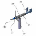
도 1의 b는 익형 날개(에어포일)의 개념도이고, 도 2는 본 발명에 따른 흐름 발전 장치의 사시도로서 이를 참고하여 본원발명의 구성을 설명하면 하기와 같다.FIG. 1B is a conceptual view of a bladed blade (airfoil), and FIG. 2 is a perspective view of a flow generation device according to the present invention.
본 발명은 해저면 또는 수중부유물에 수직으로 고정되는 지지대(10);와 상기의 지지대(10)와 수직으로 결합하여 회전하는 바디(21)와 바디(21) 전면에 위치하며 회전축(22)을 중심으로 회전하는 적어도 2개 이상의 블레이드(23)가 구비되는 발전부(20); 및 상기의 블레이드(23) 반대 측 좌우 양측에 구비되는 꼬리날개 지지대(31)와 상기의 꼬리날개 지지대(31)에 각각 상측으로 수직하여 고정되며 트레일링 엣지(trailing edge)(32)가 바디(21) 외측 방향으로 향하도록 구비되는 익형의 꼬리날개(30)로 구성된 흐름 발전 장치이다.The present invention relates to a structure for supporting a ship such as a ship, which comprises a support (10) vertically fixed to the sea floor or underwater suspension, a body (21) vertically engaged with the support (10) (20) having at least two blades (23) rotating about its center; And a
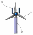
도 3은 본 발명에 따른 흐름 발전 장치의 정면도, 도 4는 본 발명에 따른 흐름 발전 장치의 평면도로서 이를 참고하여 본원발명의 상세한 구성 및 작동 방법을 설명하면 하기와 같다.FIG. 3 is a front view of the flow generating device according to the present invention, FIG. 4 is a plan view of the flow generating device according to the present invention, and the detailed configuration and operation method of the present invention will be described as follows.
조류의 흐름에 따라 블레이드(23)와 회전축(22)이 회전하고 이에 따라, 발전부(20)에서 전기가 생산된다. 흐름 발전 장치의 효율적인 요 운동으로 인한 발전효율을 최대로 유지하기 위해서는 유체 흐름 방향과 발전장치 바디(21)와의 각도가 0°에 가까운 상태여야 하며 지지대(10)와 바디(21)가 회전하도록 구성되어 블레이드의 회전력으로 인해 유체의 흐름 방향과는 달리 발전장치 바디(21)가 틀어지게 되면 발전의 효율이 떨어지게 된다. 이때, 꼬리날개(30)의 트레일링 엣지(trailing edge)(32)가 바디(21) 외측 방향으로 향하도록 구비함으로써 바디(21)가 조류와 이루는 각도가 0°가 아닐 경우 양방향에 꼬리날개(30)의 양력으로 인해 복원력이 발생한다. The
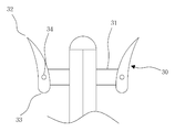
도 5은 본 발명에 따른 흐름 발전 장치의 제 2실시예 정면도로서, 상기의 꼬리날개(30) 사이에 구성되는 익형의 중앙 꼬리날개(40)가 구비되며, 상기의 중앙 꼬리날개(40)는 리딩 엣지(leading edge)(33)와 트레일링 엣지(32)가 일직선상에 위치하여 평균 캠버선이 직선인 것을 특징으로 한다. 또한, 상기의 꼬리날개 지지대(31)에 하측으로 수직하여 하측 꼬리날개(50)가 구비되는 것을 특징으로 한다.5 is a front view of a second embodiment of the flow generator according to the present invention, which is provided with a
꼬리날개(30)는 블레이드 반대 측에 수직으로 설치되며 꼬리날개(30)가 하나일 경우 발생하는 양력이 비교적 적음으로 복원력이 저하되어 발전 효율이 떨어지는 반면 꼬리날개(30)가 두 개일 경우 좌, 우 양방향으로 양력이 발생함으로써 복원력이 존재하여 발전효율을 높일 수 있는 효과가 있다. 또한, 꼬리날개(30) 사이에 구성되는 익형의 중앙 꼬리날개(34)로 좌, 우 양방향으로만 꼬리날개(30)가 구비되었을 때보다 중앙에 꼬리날개(34)를 구비함으로써 더 많은 양력을 발생할 수 있어 조류와 이루는 각도가 0°를 이룰 수 있도록 한다.The
도 6은 본 발명에 따른 흐름 발전 장치의 제 3실시예 단면도로서, 상기의 꼬리날개(30)와 꼬리날개 지지대(31) 사이에 꼬리날개 회전축(34)이 구비되어 꼬리날개(30)의 각도를 조절할 수 있는 것을 특징으로 한다. 꼬리날개 회전축(34)으로 인하여 꼬리날개(30)가 회전하므로 유체의 흐름 변화에 따라 최적의 받음 각을 만족시킬 수 있으므로 양력을 발생하여 터빈 발전 효율을 높일 수 있다.6 is a sectional view of a third embodiment of the flow generating device according to the present invention in which a tail
이에 따라, 꼬리날개의 피치각 제어장치 같은 복잡한 장치를 사용하지 않고 비교적 간단한 구조와 꼬리날개의 양력 발생으로 효율적인 요 운동을 하여 발전효율을 향상시키는 효과가 있다.Accordingly, a relatively simple structure such as a pitch angle control device of a tail wing, and a relatively simple structure and generation of lifting force of the tail wing can perform efficient yawing motion, thereby improving power generation efficiency.
본 발명은 특정의 실시 예 및 적용 예와 관련하여 도시 및 설명하였지만, 첨부된 특허청구범위에 의해 나타난 발명의 사상 및 영역으로부터 벗어나지 않는 한도 내에서 다양한 개조 및 변화가 가능 하다는 것을 당 업계에서 통상의 지식을 가진 자라면 누구나 쉽게 알 수 있을 것이다.Although the present invention has been shown and described with respect to specific embodiments and applications thereof, it will be understood by those skilled in the art that various changes and modifications may be made without departing from the spirit and scope of the invention as defined by the appended claims. Anyone with knowledge will know easily.
10. 지지대
20. 발전부
21. 바디
22. 회전축
23. 블레이드
30. 꼬리날개
31. 꼬리날개 지지대
32. 트레일링 엣지(trailing edge)
33. 리딩 엣지(leading edge)
34. 꼬리날개 회전축
40. 중앙 꼬리날개
50. 하측 꼬리날개10.
21.
23.
31.
33.
40.
Claims (4)
해저면 또는 수중부유물에 수직으로 고정되는 지지대(10);와
상기의 지지대(10)와 수직으로 결합하여 회전하는 바디(21)와 바디(21) 전면에 위치하며 회전축(22)을 중심으로 회전하는 적어도 2개 이상의 블레이드(23)가 구비되는 발전부(20); 및
상기의 블레이드(23) 반대측 좌우 양측에 구비되는 꼬리날개 지지대(31)와 상기의 꼬리날개 지지대(31)에 각각 상측으로 수직하여 고정되며 트레일링 엣지(trailing edge)(32)가 바디(21) 외측 방향으로 향하도록 구비되는 익형의 꼬리날개(30)로 구성되는 것을 특징으로 하는 흐름 발전 장치.In the flow generation device,
A support 10 vertically fixed to the sea floor or underwater suspension;
A power generating unit 20 including a body 21 rotating vertically coupled to the support 10 and at least two blades 23 positioned on the front surface of the body 21 and rotating about a rotation axis 22, ); And
A trailing edge 32 is vertically fixed to the tail wing support 31 and the tail wing support 31 provided on both sides of the blade 23 on the opposite sides of the blade 23, And a tail blade (30) of an airfoil provided so as to face toward the outside direction.
상기의 꼬리날개(30) 사이에는 익형의 중앙 꼬리날개(40)가 구비되며, 상기의 중앙 꼬리날개(40)는 리딩 엣지(33)와 트레일링 엣지(32)가 일직선 상에 위치하여 평균 캠버선이 직선인 것을 특징으로 하는 흐름 발전 장치.The method according to claim 1,
A center tail blade 40 of an airfoil is provided between the tail wings 30 so that the leading edge 33 and the trailing edge 32 of the center tail blade 40 are positioned in a straight line, And the line is a straight line.
상기의 꼬리날개(30)와 꼬리날개 지지대(31) 사이에 꼬리날개 회전축(34)이 구비되어 꼬리날개(30)의 각도를 조절할 수 있는 것을 특징으로 하는 흐름 발전 장치.The method according to claim 1,
Wherein a tail wing rotation axis (34) is provided between the tail wing (30) and the tail wing support (31) to adjust the angle of the tail wing (30).
상기의 꼬리날개 지지대(31)에 하측으로 수직하여 하측 꼬리날개(50)가 구비되는 것을 특징으로 하는 흐름 발전 장치.
3. The method according to claim 1 or 3,
And a lower tail blade (50) is provided on the tail blade support (31) perpendicular to the lower side.
Priority Applications (1)
| Application Number | Priority Date | Filing Date | Title |
|---|---|---|---|
| KR1020160003064A KR20170084382A (en) | 2016-01-11 | 2016-01-11 | Current Power Device |
Applications Claiming Priority (1)
| Application Number | Priority Date | Filing Date | Title |
|---|---|---|---|
| KR1020160003064A KR20170084382A (en) | 2016-01-11 | 2016-01-11 | Current Power Device |
Publications (1)
| Publication Number | Publication Date |
|---|---|
| KR20170084382A true KR20170084382A (en) | 2017-07-20 |
Family
ID=59443278
Family Applications (1)
| Application Number | Title | Priority Date | Filing Date |
|---|---|---|---|
| KR1020160003064A KR20170084382A (en) | 2016-01-11 | 2016-01-11 | Current Power Device |
Country Status (1)
| Country | Link |
|---|---|
| KR (1) | KR20170084382A (en) |
-
2016
- 2016-01-11 KR KR1020160003064A patent/KR20170084382A/en not_active Application Discontinuation
Similar Documents
| Publication | Publication Date | Title |
|---|---|---|
| JP3451085B1 (en) | Windmill for wind power generation | |
| AU2008267780B2 (en) | A wind turbine having an airflow deflector | |
| JP5002309B2 (en) | Horizontal axis windmill | |
| US20150061294A1 (en) | Magnus type wind power generator | |
| JP2008202588A (en) | Wind/hydraulic power impeller using lift-drag force by double-acting rotations | |
| US20080019832A1 (en) | Turbine/rotorcraft/oar blade | |
| JP2004084590A (en) | Wind mill with winglet | |
| KR20190042141A (en) | Automatic regulator of wind generator blade angle | |
| KR20170084382A (en) | Current Power Device | |
| KR101562384B1 (en) | A rudder and brake with wind power generator | |
| JP6025869B2 (en) | Windmill and its driving method | |
| KR20140069884A (en) | Wind power generation of vertical type | |
| KR20220093994A (en) | Rotating Fan Apparatus With Controllable Pitch For Flettner Rotors | |
| KR101526236B1 (en) | blade cap for wind generator | |
| JP2011089456A (en) | Vertical axis wind turbine with three-dimensional wing | |
| JP6524396B2 (en) | Wave power generation turbine | |
| US20180355845A1 (en) | Low friction vertical axis-horizontal blade wind turbine with high efficiency | |
| JP6354051B2 (en) | Wave power turbine | |
| KR101591866B1 (en) | Floating offshore power generation plant | |
| WO2022202358A1 (en) | Windmill and wind power generator | |
| JP6398095B2 (en) | Power equipment | |
| CN210317596U (en) | Lift type vertical axis fan | |
| JP2006291886A (en) | Method of producing power from moving fluid with high efficiency | |
| GB2404699A (en) | A turbine | |
| JP7180057B2 (en) | Magnus type thrust generator, wind power generator, hydraulic power generator, tidal power generator using the Magnus type thrust generator, and wind power generator, water power generator, tidal power generator using the Magnus type thrust generator |
Legal Events
| Date | Code | Title | Description |
|---|---|---|---|
| A201 | Request for examination | ||
| E902 | Notification of reason for refusal | ||
| E902 | Notification of reason for refusal | ||
| E601 | Decision to refuse application |