WO2017002578A1 - エンジンの制御装置 - Google Patents
エンジンの制御装置 Download PDFInfo
- Publication number
- WO2017002578A1 WO2017002578A1 PCT/JP2016/067303 JP2016067303W WO2017002578A1 WO 2017002578 A1 WO2017002578 A1 WO 2017002578A1 JP 2016067303 W JP2016067303 W JP 2016067303W WO 2017002578 A1 WO2017002578 A1 WO 2017002578A1
- Authority
- WO
- WIPO (PCT)
- Prior art keywords
- temperature
- engine
- air
- intercooler
- downstream
- Prior art date
- Legal status (The legal status is an assumption and is not a legal conclusion. Google has not performed a legal analysis and makes no representation as to the accuracy of the status listed.)
- Ceased
Links
Images

Classifications
-
- F—MECHANICAL ENGINEERING; LIGHTING; HEATING; WEAPONS; BLASTING
- F02—COMBUSTION ENGINES; HOT-GAS OR COMBUSTION-PRODUCT ENGINE PLANTS
- F02B—INTERNAL-COMBUSTION PISTON ENGINES; COMBUSTION ENGINES IN GENERAL
- F02B29/00—Engines characterised by provision for charging or scavenging not provided for in groups F02B25/00, F02B27/00 or F02B33/00 - F02B39/00; Details thereof
- F02B29/04—Cooling of air intake supply
-
- F—MECHANICAL ENGINEERING; LIGHTING; HEATING; WEAPONS; BLASTING
- F02—COMBUSTION ENGINES; HOT-GAS OR COMBUSTION-PRODUCT ENGINE PLANTS
- F02B—INTERNAL-COMBUSTION PISTON ENGINES; COMBUSTION ENGINES IN GENERAL
- F02B37/00—Engines characterised by provision of pumps driven at least for part of the time by exhaust
-
- F—MECHANICAL ENGINEERING; LIGHTING; HEATING; WEAPONS; BLASTING
- F02—COMBUSTION ENGINES; HOT-GAS OR COMBUSTION-PRODUCT ENGINE PLANTS
- F02D—CONTROLLING COMBUSTION ENGINES
- F02D45/00—Electrical control not provided for in groups F02D41/00 - F02D43/00
-
- Y—GENERAL TAGGING OF NEW TECHNOLOGICAL DEVELOPMENTS; GENERAL TAGGING OF CROSS-SECTIONAL TECHNOLOGIES SPANNING OVER SEVERAL SECTIONS OF THE IPC; TECHNICAL SUBJECTS COVERED BY FORMER USPC CROSS-REFERENCE ART COLLECTIONS [XRACs] AND DIGESTS
- Y02—TECHNOLOGIES OR APPLICATIONS FOR MITIGATION OR ADAPTATION AGAINST CLIMATE CHANGE
- Y02T—CLIMATE CHANGE MITIGATION TECHNOLOGIES RELATED TO TRANSPORTATION
- Y02T10/00—Road transport of goods or passengers
- Y02T10/10—Internal combustion engine [ICE] based vehicles
- Y02T10/12—Improving ICE efficiencies
Definitions
- the present invention relates to a particulate material (particulate) of an internal combustion engine, in particular a supercharged engine. Matters; hereinafter referred to as PM) relates to emission reduction technology.
- the engine using the DI system injects fuel directly into the cylinder
- the amount of fuel adhering to the inner wall of the cylinder is not less than that of a system injecting fuel upstream of the intake valve (hereinafter referred to as PFI system).
- PFI system a system injecting fuel upstream of the intake valve
- the amount of PM emission is reduced by optimizing the spray shape of the fuel injection valve (hereinafter referred to as the injector), lowering the penetration, increasing the fuel injection pressure (hereinafter referred to as the fuel pressure), and increasing the number of injection stages. Reduction technology is being built.
- the operating condition with a large amount of PM emission is a so-called cold state until the engine is started at a temperature equivalent to the outside air temperature and becomes a normal operation temperature, so-called warm-up state.
- the wall surface temperature in the cylinder is lower than that in the warm state, so that the injected fuel is more likely to adhere and hardly vaporize, and the particles of the injected fuel are less likely to vaporize.
- Increasing the internal temperature early can be effective in reducing PM emissions.
- the turbo engine is equipped with an intercooler that cools the supercharged air in order to improve the output during high-load operation. Since this intercooler is always functioning, the intake air temperature is relatively low. Thus, fuel vaporization is hindered.
- Patent Document 1 introduces a technique for increasing the intake air temperature by bypassing the intercooler in order to expand the operation range of compression ignition combustion.
- a technology that expands the lean burn operation range by increasing the intake air temperature by bypass is introduced.
- the engine In the case of a downsizing turbo engine, the engine is operated under relatively high supercharging pressure. In high supercharging operation, the mixture is enriched to protect the engine and the injection is adapted to the base small displacement. The amount of PM emission further increases due to an increase in adhered fuel due to an increase in spray penetration because the fuel injection valve having a quantity characteristic is driven under a high fuel pressure.
- Patent Document 1 and Patent Document 2 it is possible to guide the intake air whose temperature has been increased by supercharging to the cylinder while maintaining the high temperature by bypassing the intercooler, It can be expected to reduce PM emissions.
- Patent Document 1 since the technology introduced in Patent Document 1 and Patent Document 2 focuses on combustion acceleration, in Patent Document 1, the higher the engine speed, the higher the engine speed.
- Patent Document 2 As the load is lower, the intercooler bypass air amount is increased and the engine intake air temperature is increased as the engine load is lower. Therefore, there has been a problem that problems such as output reduction and knocking may occur.
- an object of the present invention is to suppress the output reduction and the occurrence of knocking while reducing the PM emission amount of the engine with a supercharger.
- the present invention has been made to solve such a problem, and is an engine control device that controls an engine connected to a supercharger and an intercooler that cools air downstream of the supercharger.
- a temperature control means for controlling an air temperature downstream of the intercooler, and the temperature control means determines an air temperature downstream of the intercooler when at least one of an engine cooling water temperature and an engine lubricating oil temperature is equal to or lower than a set temperature. Control is performed such that the temperature is raised to an air temperature higher than the upstream side of the supercharger.
- FIG. 1 is a schematic diagram of an engine and an engine control device according to an embodiment of the present invention.
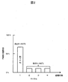
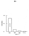
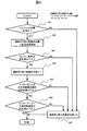
- PM emissions correlation graph by cycle in vehicle running cycle from cold to warm PM emission rate correlation graph by mode in the vehicle running cycle in cold state Control flow chart of one embodiment of the present invention
- FIG. 1 shows an overall configuration of an engine and an engine control apparatus according to an embodiment of the present invention.
- the engine is an in-cylinder direct injection type 4-cycle engine having an injection valve that directly injects fuel into the cylinder, and is an engine control unit (hereinafter referred to as ECU) composed of an MPU, I / O LSI, input / output circuit, and the like.
- ECU engine control unit
- An engine control device capable of comprehensively controlling the fuel injection amount, fuel pressure, ignition timing, knocking, and the like is provided.
- the engine and the engine control device detect the crank angle (position) and the rotation speed with the crank angle sensor 3, and the air amount measured directly or indirectly by the air flow sensor 4 or the intake pipe pressure sensor 5.
- the fuel corresponding to the above is injected from the injector 6 at an appropriate timing, and the ignition coil 7 is moved at the ignition timing retrieved from the charging timing calculated from the charging efficiency calculated from the air amount or the axis of the load value and the rotational speed. It is based on driving and igniting.
- the appropriate injection timing described above is set approximately once or a plurality of times during the intake stroke, is injected at a preset fuel pressure, and the injected fuel does not adhere to the inner wall surface of the cylinder as much as possible and is vaporized. It is easy to produce a homogeneous mixture.
- the set value of the ignition timing map is set so as to maximize the fuel consumption and output of the engine, and when it is determined that knocking is present based on the signal detected by the knock sensor 2, the ignition timing is corrected to be retarded. It is supposed to be.
- the engine coolant temperature sensor 8 is a sensor that detects the temperature of the engine before starting and after starting, and at the time of cold start, depending on the temperature of the engine, that is, the in-cylinder temperature at which fuel is injected, This is an important sensor for adjusting the fuel injection amount in consideration of the fuel adhering amount and the fuel vaporization delay, and can detect the warm-up state of the engine after starting.
- the engine lubricating oil temperature sensor 9 is provided mainly for operation compensation of a hydraulically driven variable valve timing control device (not shown in detail). That is, the control device detects the viscosity change due to the temperature of the lubricating oil. On the other hand, by using this sensor signal, it is possible to detect the warming-up state of the piston crown that cannot be estimated only by the engine cooling water temperature sensor described above. (Details will be described later).
- the electric throttle valve 10 is built in so as to detect engine torque required by a vehicle driver (hereinafter referred to as a driver) from a signal of an accelerator pedal opening sensor (not shown) and generate the required torque.
- a driver vehicle driver
- an accelerator pedal opening sensor not shown
- This is the main device of a so-called torque on demand control device that determines the throttle valve opening from an electric motor and an opening sensor.
- the compressor 11 and the exhaust turbine 12 are so-called turbochargers in which the respective wheels are integrally formed as a single unit.
- a turbine wheel in which the engine is operated at a high load and rotational force is given by high-temperature and high-pressure exhaust gas.
- the upstream side of the compressor 11 outside air, atmospheric pressure
- the volumetric efficiency of the air guided into the engine cylinder can be increased.
- the engine generated torque is increased by increasing the engine torque.
- the exhaust turbine 12 is provided with a so-called waste gate valve capable of adjusting the amount of exhaust gas guided to the turbine, so that the opening degree is adjusted so as to achieve a target supercharging pressure. It has become.
- the intercooler 13 is air-cooled, and when the engine is operating at a high load, the temperature of the high-temperature intake air supercharged by the supercharger is lowered by heat exchange with the outside air to reduce the occurrence of knocking. The charging efficiency of the introduced air is increased, and the supercharging effect is kept high. Note that, because of its function, it is general that the entire amount of intake air passes through the intercooler.
- an intercooler bypass passage 14 and an air passage switching control valve 15 capable of switching the intake air downstream of the supercharger to the intercooler 13 or the intercooler bypass passage 14 are provided. To do.
- Figure 2 shows a cycle of a traveling vehicle speed pattern, including acceleration and deceleration from start to start, using a vehicle equipped with a downsizing DI turbo engine with specifications for engine displacement, compression ratio, engine coolant and engine lubricant.
- PM emission amount of each cycle when the engine is operated until the end of the four cycles when the engine is warmed up is expressed as a percentage of the total of the four cycles.
- the engine cooling water temperature at the start is 25 ° C. (normal temperature), and the engine cooling water temperature at the end of one cycle is about 50 ° C.
- the PM emission ratio at that time is 70% of the total of four cycles. Has reached.
- the PM emission rate ratio in the subsequent cycles is about 10%, it can be seen that the PM emission rate is not affected by the engine cooling water temperature when the engine cooling water temperature passes through a cold state of about 50 ° C. or less. .
- the cold state of the engine is judged from the engine cooling water temperature and the engine lubricating oil temperature, and the temperature downstream of the intercooler 13, that is, the air that is guided into the engine cylinder
- the temperature downstream of the intercooler 13 that is, the air that is guided into the engine cylinder
- the amount of PM emission is larger than that in the warm state.
- the engine cylinder inner wall temperature is low, knocking is less likely to occur. Even if it raises, there is little bounce and it is convenient.
- the temperature detected by the engine cooling water temperature sensor 8 is basically referred to.
- a piston cooling device engine lubricating oil is placed on the back surface of the piston crown surface.
- a mechanism for injecting oil such as a piston with a cooling channel and an oil jet, is employed, the temperature of the piston crown is affected by the temperature of the engine lubricating oil. It is desirable to refer to it.
- the “temperature at which it is possible to determine that the engine is not in a warm-up state” described in claim 4 of the present invention is the control permission determination upper limit temperature, and if the engine cooling water temperature is set to about 50 ° C. as described above.
- the temperature when the temperature is set by the engine lubricating oil temperature, it may be set in view of the fact that the engine lubricating oil temperature is lower than the engine cooling water temperature, but in any case, for example, the PM described in FIG. It is necessary to adapt to the specification (warm-up characteristics) of the target vehicle using the emission evaluation method.
- the air downstream of the intercooler 13 is raised.
- the air is supercharged by the compressor 11 and the upstream air ( A method is adopted in which the downstream air whose temperature has risen relative to the outside air is guided into the engine cylinder without passing through the intercooler 13.
- intercooler 13 is a heat exchanger
- energy is necessary for the heat source, and if it can be obtained from waste energy such as exhaust gas and deceleration regenerative energy, there will be no impact on fuel consumption and output, but stable enjoyment of waste energy and system layout design will be possible. It is not realistic considering the difficulty and cost.
- an intercooler bypass passage 14 and an air passage switching control valve 15 are provided beside the intercooler 13, and when the engine is determined to be cold, the air downstream of the compressor 13 is bypassed by the intercooler bypass.
- the air passage switching control valve 15 is controlled so as to pass through the passage 14.
- the air passage switching control valve is driven by a DC motor according to a command from the ECM 1 and is controlled to a target opening position by an opening position sensor.
- the air passage switching control valve 15 is controlled to flow through the intercooler bypass passage 14 so that the air downstream of the compressor 11 is not cooled by the intercooler 13, but in the first place, The temperature downstream of the compressor 11 is not always supercharged.
- FIG. 3 shows the PM emission by classifying the driving mode in the driving pattern into “acceleration”, “steady”, “deceleration” and “idle” for the first cycle (engine cold state) among the driving patterns described in FIG. It is the graph which represented the quantity in the ratio which occupies for the whole cycle.
- the engine is operated at a high load as described in claims 5 to 6 "according to the predetermined range excluding the maximum load of the engine, that is, the acceleration operation that is not the maximum load".
- the air passage switching control valve 15 is controlled so that the air downstream of the compressor 11 passes through the intercooler bypass passage 14.
- the air passage switching control valve 15 is set so that the air downstream of the compressor 11 passes through the intercooler bypass passage 14 on the condition that the engine operating load is within a predetermined range excluding the maximum load. Is controlling.
- the “acceleration” mode in which the engine is operated at a relatively high load for example, when the air temperature upstream of the compressor 11 ( ⁇ outside air temperature) is about 25 ° C., it is caused by supercharging. Due to the temperature rise effect, the temperature downstream of the compressor 11 reaches about 50 ° C. to 75 ° C. (in the same vehicle, the higher the displacement, the higher the temperature), so that the air passes through the intercooler bypass passage 14 and enters the engine cylinder. By introducing it, the vaporization of the injected fuel is greatly promoted and the PM emission amount is reduced.
- the predetermined range is set to be equal to or lower than the upper limit value of the engine operating load, and various physical parameters (parameters) of the engine operating load such as an accelerator pedal opening, a throttle opening, and an intake pipe pressure can be considered.
- the estimated torque ( ⁇ actual torque) calculated by the torque-on-demand control apparatus is used as an index.
- the torque-on-demand control device calculates the required torque from the accelerator pedal opening, and takes into account the combustion state of the engine, the loss torque, and the like so that the required torque can be generated. Since the estimated torque is calculated as the feedback control parameter by adjusting the waste gate valve opening of the engine, it is convenient that the engine operating load state is expressed in real time.
- the upper limit value of the estimated torque may be set to about 80% of the target torque. More specifically, in the target engine, the occurrence of knocking or the downstream of the compressor 13 depends on the engine cold state described above. It is necessary to adjust the temperature while checking the temperature.
- the air temperature downstream of the intercooler is predicted to cause knocking.
- the control of the air passage switching valve 15 controls the intercooler 13. Since air is flowed through and cooled, the occurrence of knocking is suppressed.
- the “temperature at which knocking is predicted to occur” is set based on the result of confirming in advance the correlation between the temperature of the air led into the cylinder of the engine ( ⁇ intake pipe temperature) and the occurrence of knocking.
- the temperature detection may be performed based on the information of the temperature sensor built in the intake pipe pressure sensor 5.
- the “predetermined value of the retardation correction amount by knocking” is set so that the retardation correction amount is about 1 to 2 deg in the warm-up state knock control. What is necessary is just to set to 3-5 deg.
- the engine warm-up state determination unit 401 determines whether or not the engine is in a cold state based on the engine cooling water temperature or the engine lubricating oil temperature.
- the air passage switching control valve operating unit 3 407 switches the air passage switching control valve 15 so that the air downstream of the compressor 11 is guided to the intercooler 13 side and is terminated.
- the air passage switching control valve operation unit 1 402 moves to the engine load state determination unit 403 while maintaining the position of the air passage switching control valve 15 set at the previous end. .
- the engine load state determination unit 403 is in the maximum load state, End with the same operation.
- the air passage switching control valve operation unit 404 switches the position of the air passage switching control valve 15 so that the air downstream of the compressor 11 is guided to the intercooler bypass passage 14 side. .
- the intercooler downstream air temperature determination unit 406 further When it is determined that the air temperature downstream of the intercooler is equal to or higher than the temperature at which knocking is predicted, the air passage switching control valve operating unit 3 407 moves the position of the air passage switching control valve 15 to the compressor 11. Since switching is performed so that the downstream air is guided to the intercooler bypass passage 14 side, undesirable knocking is suppressed.
- the PM emission amount can be effectively suppressed while avoiding problems such as knocking under operating conditions with a large PM emission amount, and PM reduction control with high robustness is possible.
Landscapes
- Engineering & Computer Science (AREA)
- Chemical & Material Sciences (AREA)
- Combustion & Propulsion (AREA)
- Mechanical Engineering (AREA)
- General Engineering & Computer Science (AREA)
- Physics & Mathematics (AREA)
- Thermal Sciences (AREA)
- Combined Controls Of Internal Combustion Engines (AREA)
- Output Control And Ontrol Of Special Type Engine (AREA)
Abstract
ノッキングなどの不具合を回避しつつ、ロバスト性が高く、効果的なPM排出量低減技術を提供すること。過給器と、前記過給器の下流の空気を冷却するインタークーラーと、に接続されるエンジンを制御するエンジン制御装置であって、前記インタークーラーの下流の空気温度を制御する温度制御手段を備え、前記温度制御手段は、エンジン冷却水温、及びエンジン潤滑油温の少なくともひとつが設定温度以下のとき前記インタークーラーの下流の空気温度を、前記過給器の上流側の空気温度以上に上昇させるように制御する。
Description
本発明は、内燃機関、特に過給器付きエンジンの粒子状物質(Particulate
Matter;以下PMと記す)排出量低減技術に関する。
Matter;以下PMと記す)排出量低減技術に関する。
ガソリンエンジンを搭載した自動車では、燃費向上及びCO2排出量低減のため、比較的排気量の小さい(1.0~2.0L)過給機付きエンジン、所謂ダウンサイジングターボエンジンの採用が増加しつつある。さらに、ダウンサイジングターボエンジンには、高圧縮比化が可能で熱効率に優れた筒内直接燃料噴射システム(以下、DIシステムと記す)が採用されることが多い。
一方、DIシステムを採用したエンジンは、筒内に直接燃料噴射するため、吸気弁上流で燃料噴射するシステム(以下、PFIシステムと記す)に比べ、少なからず筒内壁面への燃料付着量の増加、及び気化率の低下による混合気均質度の低下が発生しやすく、拡散燃焼によりPMの排出量が多くなる。
そこで、DIシステムにおいては、燃料噴射弁(以下、インジェクタと記す)の噴霧形状最適化、低ペネトレーション化、燃料噴射圧力(以下、燃圧と記す)の高圧化、噴射多段化等によって、PM排出量低減技術を構築しつつある。
ところが、筒内デポジット堆積などの使用経時的なPM排出量増加に対応するため、外乱やばらつきに強い、所謂ロバスト性の高いPM排出量低減技術の要求が高まってきており、そのためには、エンジンの全運転条件のうちPM排出量が多いエンジンの運転条件での改善が重要となる。
PM排出量が多い運転条件は、エンジンが外気温と同等の温度で始動され、通常運転温度、所謂暖機状態となるまでの間、所謂冷機状態であり、暖機状態ではPM排出量は大幅に低減することがわかっている。
冷機状態は暖機状態に比べ筒内壁面温度が低いため、噴射燃料が付着しやすく且つ気化しにくいことと、噴射された燃料の粒子が気化しにくいことが要因として挙げられ、壁面を含む筒内温度を早期に上昇させることがPM排出量低減に有効となり得る。
しかし、ターボエンジンには、高負荷運転時の出力向上のため、過給された空気を冷却するインタークーラーが備えられており、本インタークーラーが常時機能していることから、吸入空気温度が比較的低くなり、燃料の気化を阻害することとなる。
ところで、特許文献1に紹介されている技術では、圧縮自着火燃焼の運転範囲を拡大するために、前記インタークーラーをバイパスさせて、吸入空気温度を上昇させる手法が紹介され、特許文献2でも、インタークーラーバイパスによる吸気温度上昇で希薄燃焼運転範囲の拡大を図る技術が紹介されている。
ロバスト性の高いPM排出量低減技術を構築する上で、エンジン冷機状態での筒内温度の早期上昇が有効であると前述したが、エンジン冷却水温やエンジン潤滑油温を含むエンジン全体の温度を早期に上昇させて暖機状態とすることは困難である。
また、ダウンサイジングターボエンジンであれば、比較的過給圧の高い条件で運転されることとなり、高過給運転ではエンジン保護のための混合気エンリッチや、ベースとなる小排気量に適応した噴射量特性をもつ燃料噴射弁を、高燃圧下で駆動させるが故の噴霧ペネトレーションの長大化による付着燃料増加によって、さらにPM排出量が増加する。
そこで、特許文献1、及び特許文献2で紹介されているように、過給によって温度が上昇した吸入空気を、インタークーラーをバイパスさせることで、高温を保ったまま筒内に導くことが可能となり、PM排出量低減にも効果が期待できる。
しかし、特許文献1、及び特許文献2で紹介されている技術は、燃焼促進に主眼を置いているため、エンジンの温度状態に係りなく、特許文献1では、エンジン回転数が高いほど、及びエンジン負荷が低いほど、特許文献2では、エンジン負荷が低いほど、インタークーラーバイパス空気量を増大させて、エンジン吸入空気温度を上昇させるようにしている。したがって、出力低下やノッキングなどの不具合が発生し得るという問題があった。
そこで本発明の目的は、過給機付きエンジンについて、PM排出量を低減しつつ、出力低下やノッキングの発生を抑制することにある。
本発明は、係る問題を解決するためになされたものであり、過給器と、前記過給器の下流の空気を冷却するインタークーラーと、に接続されるエンジンを制御するエンジン制御装置であって、前記インタークーラーの下流の空気温度を制御する温度制御手段を備え、前記温度制御手段は、エンジン冷却水温、及びエンジン潤滑油温の少なくともひとつが設定温度以下のとき前記インタークーラーの下流の空気温度を、前記過給器の上流側の空気温度以上に上昇させるように制御することを特徴とする。
本発明によれば、過給機付きエンジンについて出力低下やノッキングの発生を抑制しつつ、PM排出量を低減させることが可能となる。
なお、上記した以外の本発明の構成、作用、効果については以下の実施例において詳細に説明する。
なお、上記した以外の本発明の構成、作用、効果については以下の実施例において詳細に説明する。
以下、図面に基づき、本発明であるエンジン制御装置の一実施形態について説明する。本実施例では、PM排出量が多いエンジン運転条件、すなわち冷機状態は、過給によって吸入空気温度が上昇した高負荷運転でも、ノッキングが発生しにくいことと、冷機状態は暖機状態までの通過過程であってエンジン全運転条件の一部であることに着目し、冷機状態に条件を制限して、高温の吸入空気を筒内に導くようにしているが、まず、第一に、本発明に係わるエンジン及びエンジン制御装置の基本的な動作概要について説明する。
図1は、本発明の一実施形態に係わるエンジンと、エンジン制御装置の全体構成を示したものである。エンジンは筒内に直接燃料を噴射する噴射弁を有する、筒内直接噴射式4サイクルエンジンとしており、MPU、I/O LSI、入出力回路等で構成されたエンジンコントロールユニット(以下、ECUと称す)1で燃料噴射量、燃圧、点火時期、ノッキング等を総合的に制御可能なエンジン制御装置を備えている。
図1は、本発明の一実施形態に係わるエンジンと、エンジン制御装置の全体構成を示したものである。エンジンは筒内に直接燃料を噴射する噴射弁を有する、筒内直接噴射式4サイクルエンジンとしており、MPU、I/O LSI、入出力回路等で構成されたエンジンコントロールユニット(以下、ECUと称す)1で燃料噴射量、燃圧、点火時期、ノッキング等を総合的に制御可能なエンジン制御装置を備えている。
前記エンジン及びエンジン制御装置は、クランク角センサ3でクランク角(位置)、及び回転数を検知し、エアフローセンサ4、または吸気管圧力センサ5にて、直接的または間接的に計測された空気量に見合った燃料を、インジェクタ6から適切な時期で噴射し、空気量から計算される充填効率または負荷値と回転数の軸で設定された点火時期マップから検索された点火時期で点火コイル7を駆動して点火することを基本としている。
なお、前記した適切な噴射時期は、概ね吸気行程中に1回ないし複数回設定され、予め設定された燃圧で噴射され、噴射された燃料が可能な限り筒内壁面付着せず、且つ気化されやすい状態となって、均質混合気を生成するようにしている。
また、前記した点火時期マップの設定値は、エンジンの燃費及び出力が最大限引き出されるように設定され、ノックセンサ2で検出した信号によってノッキングありと判定されたときは、点火時期を遅角補正するようになっている。
エンジン冷却水温センサ8は、始動前、始動後のエンジンの温度を検知するセンサであり、冷機始動時においては、エンジンの温度、すなわち燃料が噴射される筒内温度に応じて、筒内壁面への燃料付着分や燃料気化の遅れ分を考慮して燃料噴射量を調整するために重要なセンサで、始動後においては、エンジンの暖機状態を検知し得るようになっている。
エンジン潤滑油温センサ9は、主に油圧駆動の可変バルブタイミング制御装置(詳細は図示せず)の動作補償のために備えられており、すなわち潤滑油の温度による粘性変化を捉えて前記制御装置の動作を安定させるために重要なセンサで、一方では本センサ信号を利用することにより、前述のエンジン冷却水温センサのみでは推し量れないピストン冠面の暖機状態を検知し得るようになっている(詳細は後述する)。
電制スロットルバルブ10は、アクセルペダル開度センサ(図示せず)の信号から、車両運転者(以下、ドライバーと記す)が要求するエンジントルクを検知し、その要求トルクを発生させるように内蔵された電気モーターと開度センサから、スロットルバルブ開度を決定する、所謂トルクオンデマンド制御装置の主たる機器である。
コンプレッサ11と排気タービン12は、夫々のホイールが同軸一体で形成されている、所謂ターボ過給器であり、エンジンが高負荷運転され、高温高圧の排気ガスにより回転力を与えられたタービンホイールと同軸のコンプレッサホイールを回転させることにより、コンプレッサ11上流側の空気(外気、大気圧)対して下流側を大気圧以上に加圧(過給)でき、エンジン筒内に導かれる空気の体積効率を増加させて、エンジン発生トルクを増大させるようになっている。また、排気タービン12には、タービンに導かれる排気ガス量が調整可能なバイパス弁、所謂ウエイストゲートバルブが備えられており、目標とする過給圧となるように開度が調整されるようになっている。
インタークーラー13は空冷式としており、エンジンが高負荷運転時、過給器で過給された高温の吸入空気を外気との熱交換によって温度を下げ、ノッキングの発生を低減するとともに、エンジン筒内に導入される空気の充填効率を増加させて、過給効果を高く維持するようになっている。なお、その機能故、吸入空気全量がインタークーラーを通過する構造となっているのが一般的である。
また、インタークーラーバイパス通路14と、過給器下流の吸入空気を、インタークーラー13またはインタークーラーバイパス通路14に切り替えて流すことが可能な空気通路切り替え制御弁15が備えられているが、動作内容については後述する。
第二に、本発明の基本的且つ具体的な動作内容について説明する。
前述した本発明の一実施形態に係わるエンジン及びエンジン制御装置において、インジェクタの噴霧形状や燃圧、噴射時期、1サイクル当たりの噴射回数などによって、PM排出量を最適化した場合でも、デポジット堆積などの使用経時的なPM排出量増加、あるいはインジェクタ噴霧形状の製造ばらつき、予期しない過渡時空燃比のリッチ化などによるPM排出量増加の可能性があり、PM排出量低減に関するロバスト設計は困難であった。
そこで、本発明では、前述したように、現状ではPM排出量が多い冷機状態に着目している。
図2は、排気量や圧縮比、またエンジン冷却水量やエンジン潤滑油量がある仕様のダウンサイジングDIターボエンジンを搭載した車両を用い、始動から、加減速を含む、ある走行車速パターンを1サイクルとして、エンジンが暖機状態となる4サイクル終了まで運転したときの各サイクルのPM排出量を、4サイクル全体に占める割合で表したグラフである。
始動時のエンジン冷却水温が25℃(常温)で始動され、1サイクル終了した時のエンジン冷却水温は約50℃の冷機状態であり、その時点でのPM排出量比率は4サイクル全体の70%に達している。
そして、その後のサイクルでのPM排出量比率は各々10%程度であることから、エンジン冷却水温が約50℃以下の冷機状態を経過すれば、PM排出量はエンジン冷却水温に影響されないことがわかる。
したがって、冷機始動を含めた車両走行中のPM排出量を低減するには、エンジン冷却水温が約50℃以下の冷機状態のPM排出量を低減させることが有効となる。
もちろん、噴射燃料の気化促進を図るのであれば、エンジン筒内に導く空気の温度を常時上昇させた方がPM排出量低減においては、より有効となりえるが、闇雲に空気温度上昇させれば、充填効率低下やノッキングの発生、更にはノッキング発生に伴う点火時期遅角による燃費性能の低下等の跳ね返り(不具合)が発生し、都合が悪い。
そこで本発明の請求項1及び請求項2及び請求項4によれば、エンジン冷却水温及びエンジン潤滑油温からエンジンの冷機状態を判断し、インタークーラー13下流の温度、すなわちエンジン筒内に導く空気の温度を上昇させることにより、筒内噴射燃料の気化を促進させるようにしている。
エンジン冷機状態では暖機状態に比べ、PM排出量が多い一方、エンジン筒内壁温が低いためにノッキングが発生しにくいという性質があることから、エンジン冷機状態にエンジン筒内に導く空気の温度を上昇させても跳ね返りが少なく都合がよい。
なお、エンジンの冷機状態を判断する場合、基本的にエンジン冷却水温センサ8で検知した温度を参照しているが、エンジン高出力対応のためにピストン冷却装置(ピストン冠面の裏面にエンジン潤滑油を噴射する機構、例えばクーリングチャンネル付きピストンとオイルジェット)が採用されている場合は、ピストン冠面の温度はエンジン潤滑油温の影響を受けることから、エンジン潤滑油温センサ9で検知した温度を参照することが望ましい。
そこで、本発明の請求項4に記載した、「エンジンが暖機状態でないと判断可能な温度」は制御許可判断上限温度であり、前述したようにエンジン冷却水温で約50℃程度に設定すればよく、前記温度をエンジン潤滑油温で設定する場合は、エンジン冷却水温よりエンジン潤滑油温の方が低くなることを鑑みて設定すればよいが、いずれにしても、例えば図2で説明したPM排出量評価手法を用いて、対象車両の仕様(暖機特性)に適合させる必要がある。
さて、エンジンが冷機状態と判断されているときはインタークーラー13下流の空気を上昇させるが、その方法として本発明では、請求項3に記載したように、コンプレッサ11で過給され、上流の空気(概ね外気)に対して温度が上昇した下流の空気を、インタークーラー13を通過させずにエンジン筒内に導く手法を採用している。
インタークーラー13下流の温度を上昇させる手段としては、他にも考えられ、例えば、インタークーラー13は熱交換器であるから、外部から熱を与える方法もある。しかし、熱源にはエネルギーが必要であり、そのエネルギーを排気ガスや減速回生エネルギーなどの廃エネルギーから得られれば燃費や出力への影響はないが、廃エネルギーの安定的な享受とシステムレイアウト設計が困難であること、更にはコスト等を考慮すると現実的ではない。
そこで、図1に示したように、インタークーラー13の傍らに、インタークーラーバイパス通路14と空気通路切り替え制御弁15を備え、エンジンが冷機状態と判断されているときは、コンプレッサ13下流の空気がインタークーラーバイパス通路14を通過するように、空気通路切り替え制御弁15を制御している。
なお、空気通路切り替え制御弁は、ECM1の指令によって直流モーターで駆動され、開度位置センサによって目標開度位置に制御されるようになっている。
以上、エンジンが冷機状態であると判断されているときには、コンプレッサ11下流の空気をインタークーラー13で冷却されないように、インタークーラーバイパス通路14を流すように空気通路切り替え制御弁15を制御するが、そもそも、コンプレッサ11下流の温度が常時過給昇温されるとは限らない。
図3は、図2で説明した走行パターンのうち、1サイクル目(エンジン冷機状態)について、走行パターン中の走行モードを「加速」「定常」「減速」「アイドル」に分類して、PM排出量を1サイクル全体に占める割合で表したグラフである。
エンジンが比較的高負荷で運転される「加速」が排出量の約80%を占めており、図2で説明した冷機状態でのPM排出量割合と掛け合わせると、56%であり、冷機状態且つ加速運転でのPN排出量低減効果が最大となることがわかる。
そこで、本発明では、請求項5ないし請求項6に記述した、「エンジンの運転負荷が最
大負荷を除く所定範囲」、すなわち最大負荷ではない程度の加速運転のように、エンジンが高負荷運転されて過給によるコンプレッサ11下流の空気温度が上昇しているときに、コンプレッサ11下流の空気がインタークーラーバイパス通路14を通過するように、空気通路切り替え制御弁15を制御する。
大負荷を除く所定範囲」、すなわち最大負荷ではない程度の加速運転のように、エンジンが高負荷運転されて過給によるコンプレッサ11下流の空気温度が上昇しているときに、コンプレッサ11下流の空気がインタークーラーバイパス通路14を通過するように、空気通路切り替え制御弁15を制御する。
ただし、車両動力性能要求から決定されたエンジンの出力特性が発揮されるエンジンの運転負荷は最大負荷状態であり、充填効率が最大となるようインタークーラー13によって、エンジン筒内に導く空気の温度を低下させる必要があるため、本発明ではエンジンの運転負荷が最大負荷を除く所定範囲であることを許可条件として、コンプレッサ11下流の空気がインタークーラーバイパス通路14を通過するように、空気通路切り替え制御弁15を制御している。
なお、ダウンサイジングターボエンジンでは、エンジンが比較的高負荷で運転される「加速」モードにおいて、例えば、コンプレッサ11上流の空気温度(≒外気温度)が約25℃程度であった場合、過給による昇温効果により、コンプレッサ11下流の温度は、50℃ないし75℃程度(同一車両では排気量が小さいほど高くなる)に達するので、該空気を、インタークーラーバイパス通路14を通過させてエンジン筒内に導入することで噴射燃料の気化が大幅に促進され、PM排出量が低減されることになる。
ところで、前記所定範囲は、エンジンの運転負荷の上限値以下に設定され、エンジンの運転負荷の物理的指標(パラメータ)としては、アクセルペダル開度、スロットル開度、吸気管圧力など様々考えられるが、本発明の一実施形態では、トルクオンデマンド制御装置によって演算された推定トルク(≒実トルク)を指標としている。
トルクオンデマンド制御装置は、アクセルペダル開度から要求トルクを演算し、その要求トルクを発生し得るように、エンジンの燃焼状態や損失トルクなどを加味して、電制スロットルバルブ10と排気タービン12のウエイストゲートバルブ開度を調整し、且つフィードバック制御パラメータとして推定トルクを演算しているため、エンジン運転負荷状態がリアルタイムで表現されていて都合がよい。
なお、前記推定トルクの上限値設定は、目標トルクの約80%程度とすればよいが、詳しくは、対象とするエンジンで、前述したエンジン冷機状態に応じて、ノッキングの発生状況やコンプレッサ13下流の温度を確認しながら適合させる必要がある。
以上が、請求項1ないし請求項6に記述した本発明の基本的動作内容の一実施形態であるが、前述したエンジン冷却水温上限値や、推定トルク上限値は、エンジン個体ばらつき(圧縮比など)や環境条件(外気温や湿度など)の変化によって要求値が変わり、好ましくないノッキングが発生することが予想される。
そこで、請求項7ないし請求項10に記述した内容によれば、空気通路切り替え弁15の制御によってインタークーラーバイパス通路14を空気が流れている状態において、インタークーラー下流の空気温度が、ノッキングの発生が予測される温度以上となったとき、或いは、ノックセンサ2で検出した信号によってノッキングありと判定され、点火時期が所定値以上遅角補正されたときは、空気通路切り替え弁15の制御によって、インタークーラー13に空気を流して冷却するから、ノッキングの発生が抑制される。
詳しくは、前記「ノッキングの発生が予測される温度」は、適用するエンジンにおいて、エンジンの筒内に導く空気の温度(≒吸気管内温度)とノッキング発生の相関を予め確認し、その結果から設定すればよく、温度検知は吸気管圧力センサ5に内蔵された温度センサの情報を基準にすればよい。
また、前記「ノッキングによる遅角補正量の所定値」は、遅角補正量が暖機状態のノック制御で1~2deg程度となるように設定されるから、異常を判断する値としては、これを超える3~5degに設定すればよい。
なお、これらの設定値によって空気通路切り替え弁15を動作させるときは、該設定値にヒステリシスや判定ディレー時間などを用いて、空気通路切り替え弁15が頻繁に切り替わらないようにすることが重要である。
以上の具体的な動作について、図4に示す制御フローチャートを用いて説明する。
まず、エンジン暖機状態判定部401で、前述したように、エンジン冷却水温またはエンジン潤滑油温でエンジンが冷機状態であるか否か判定する。
冷機状態でないと判定されれば、407の空気通路切り替え制御弁操作部3において、空気通路切り替え制御弁15を、コンプレッサ11下流の空気をインタークーラー13側に導くように切り替えて終了させる。
一方、冷機状態と判定されれば、402の空気通路切り替え制御弁操作部1において、前回終了時に設定された空気通路切り替え制御弁15の位置を保持したまま、エンジン負荷状態判定部403に移行する。
エンジン負荷状態判定部403では、前述したように、トルクオンデマンド制御装置で演算された推定トルクが所定の上限設定値以下でない、すなわち最大負荷状態であると判定されれば、前記冷機状態判定時と同様の動作で終了させる。
一方、最大負荷状態でないと判定されれば、404の空気通路切り替え制御弁操作部2で、空気通路切り替え制御弁15の位置を、コンプレッサ11下流の空気をインタークーラーバイパス通路14側に導くように切り替える。
以上により、冷機状態且つ最大負荷以外の状態で、過給によって加圧昇温された空気がインタークーラーで冷却されることなくエンジン筒内に導入され、噴射された燃料の気化が促進され、PM排出量が低減されるようになる。
なお、以上の状態においても、ノッキング判定部405において、前述したノッキングによる点火時期遅角補正量が所定の設定値以上となったと判定された場合、更には、インタークーラー下流空気温度判定部406において、インタークーラー下流空気温度が、前述したノッキングの発生が予測される温度以上となったと判定された場合は、407の空気通路切り替え制御弁操作部3で、空気通路切り替え制御弁15の位置を、コンプレッサ11下流の空気をインタークーラーバイパス通路14側に導くように切り替えるから、好ましくないノッキングの発生が抑制されるようになる。
以上の通り本実施例によれば、PM排出量が多い運転条件で、ノッキングなどの不具合を回避しつつ、効果的にPM排出量を抑制でき、ロバスト性の高いPM低減制御が可能となる。
以上、本発明の一実施形態について記述したが、本発明は、前記の実施形態に限定されるものではなく、特許請求の範囲に記載された本発明の精神を逸脱しない範囲で、種々の設計変更を行なうことができるものである。
1 エンジンコントロールユニット(ECU)
2 ノックセンサ
3 クランク角センサ
4 エアフローセンサ(温度センサ内臓)
5 吸気管圧力センサ(温度センサ内臓)
6 インジェクタ
7 点火コイル
8 エンジン冷却水温センサ
9 エンジン潤滑油温センサ
10 電制スロットルバルブ
11 コンプレッサ(過給器)
12 排気タービン(過給器)
13 インタークーラー
14 インタークーラーバイパス通路
15 空気通路切り替え制御弁
401 エンジン暖機状態判定部
402 空気通路切り替え制御弁操作部1
403 エンジン負荷状態判定部
404 空気通路切り替え制御弁操作部2
405 ノッキング判定部
406 インタークーラー下流空気温度判定部
407 空気通路切り替え制御弁操作部3
Claims (10)
- 過給器と、前記過給器の下流の空気を冷却するインタークーラーと、に接続されるエンジンを制御するエンジン制御装置であって、
前記インタークーラーの下流の空気温度を制御する温度制御手段を備え、
前記温度制御手段は、エンジン冷却水温、及びエンジン潤滑油温の少なくともひとつが設定温度以下のとき前記インタークーラーの下流の空気温度を、前記過給器の上流側の空気温度以上に上昇させるように制御することを特徴とするエンジン制御装置。 - 過給器と、前記過給器の下流の空気を冷却するインタークーラーと、に接続されるエンジンを制御するエンジン制御装置であって、
前記インタークーラーの下流の空気温度を制御する温度制御手段を備え、
前記温度制御手段は、エンジン冷却水温、及びエンジン潤滑油温の少なくともひとつが設定温度以下のとき前記インタークーラーの下流の空気温度を、外気温度以上に上昇させるように制御することを特徴とするエンジン制御装置。 - 過給器と、前記過給器の下流の空気を冷却するインタークーラーと、前記インタークーラーを迂回するバイパス吸気管と、前記過給器の下流の空気を前記インタークーラー又は前記バイパス吸気管に切り替えて流す空気通路切り替え弁と、に接続されるエンジンを制御するエンジン制御装置であって、
エンジン冷却水温、及びエンジン潤滑油温の少なくともひとつが設定温度以下のとき、前記過給器の下流の空気を前記バイパス吸気管側に流すように前記空気通路切り替え弁を制御することを特徴とするエンジン制御装置。 - 請求項1ないし請求項3に記載の設定温度は、エンジンが暖機状態でないと判断可能な温度以下に設定されること、を特徴とした、請求項1ないし請求項3に記載のエンジン制御装置。
- 請求項1ないし請求項2に記載の空気温度の上昇制御は、エンジンの運転負荷が最大負荷を除く所定範囲内であると判断したときに実施されること、を特徴とした、請求項1ないし請求項2に記載のエンジン制御装置。
- 請求項3に記載の空気通路切り替え弁制御は、エンジンの運転負荷が最大負荷を除く所定範囲内であると判断したときに実施されること、を特徴とした、請求項3に記載のエンジン制御装置。
- 前記温度制御手段は、エンジン冷却水温、及びエンジン潤滑油温の少なくともひとつが前記設定温度以下であっても、ノッキング検知によって点火時期が所定量遅角されたときは、前記インタークーラーの下流の空気温度を維持又は低下させるように制御することを特徴とする請求項1ないし請求項2に記載のエンジン制御装置。
- エンジン冷却水温、及びエンジン潤滑油温の少なくともひとつが前記設定温度以下であっても、ノッキング検知によって点火時期が所定量遅角されたときは、前記過給器の下流の空気を前記インタークーラーに流すように前記空気通路切り替え弁を制御することを特徴とする請求項3に記載のエンジン制御装置。
- 前記温度制御手段は、エンジン冷却水温、及びエンジン潤滑油温の少なくともひとつが前記設定温度以下であっても、前記過給器の下流の空気温度が設定温度以上になったときは、前記インタークーラーの下流の空気温度を維持又は低下させるように制御することを特徴とする請求項1ないし請求項2に記載のエンジン制御装置。
- エンジン冷却水温、及びエンジン潤滑油温の少なくともひとつが前記設定温度以下であっても、前記過給器の下流の空気温度が設定温度以上になったときは、前記過給器の下流の空気を前記インタークーラーに流すように前記空気通路切り替え弁を制御することを特徴とする請求項3に記載のエンジン制御装置。
Priority Applications (1)
| Application Number | Priority Date | Filing Date | Title |
|---|---|---|---|
| JP2017526261A JP6452816B2 (ja) | 2015-06-29 | 2016-06-10 | エンジンの制御装置 |
Applications Claiming Priority (2)
| Application Number | Priority Date | Filing Date | Title |
|---|---|---|---|
| JP2015-129462 | 2015-06-29 | ||
| JP2015129462 | 2015-06-29 |
Publications (1)
| Publication Number | Publication Date |
|---|---|
| WO2017002578A1 true WO2017002578A1 (ja) | 2017-01-05 |
Family
ID=57608113
Family Applications (1)
| Application Number | Title | Priority Date | Filing Date |
|---|---|---|---|
| PCT/JP2016/067303 Ceased WO2017002578A1 (ja) | 2015-06-29 | 2016-06-10 | エンジンの制御装置 |
Country Status (2)
| Country | Link |
|---|---|
| JP (1) | JP6452816B2 (ja) |
| WO (1) | WO2017002578A1 (ja) |
Cited By (6)
| Publication number | Priority date | Publication date | Assignee | Title |
|---|---|---|---|---|
| JP2018141378A (ja) * | 2017-02-27 | 2018-09-13 | トヨタ自動車株式会社 | 内燃機関の制御装置 |
| JP2019152188A (ja) * | 2018-03-06 | 2019-09-12 | トヨタ自動車株式会社 | 内燃機関の燃料噴射時期制御装置 |
| JP2020537477A (ja) * | 2017-10-11 | 2020-12-17 | ローベルト ボツシユ ゲゼルシヤフト ミツト ベシユレンクテル ハフツングRobert Bosch Gmbh | 駆動機械を作動させる装置および方法 |
| CN119084136A (zh) * | 2024-08-23 | 2024-12-06 | 潍柴动力股份有限公司 | 基于中冷旁通机构的温度控制装置、方法及发动机 |
| CN119099580A (zh) * | 2024-09-30 | 2024-12-10 | 东风商用车有限公司 | 一种混动发动机启停保护方法及系统 |
| CN119616730A (zh) * | 2024-12-29 | 2025-03-14 | 中国重汽集团济南动力有限公司 | 一种发动机进气预热控制系统及方法 |
Families Citing this family (1)
| Publication number | Priority date | Publication date | Assignee | Title |
|---|---|---|---|---|
| CN114961980B (zh) * | 2022-06-20 | 2023-11-17 | 中国第一汽车股份有限公司 | 一种发动机进气温度分缸控制方法及系统 |
Citations (4)
| Publication number | Priority date | Publication date | Assignee | Title |
|---|---|---|---|---|
| JPS61125632U (ja) * | 1985-01-25 | 1986-08-07 | ||
| JPS62153517A (ja) * | 1985-12-26 | 1987-07-08 | Toyota Motor Corp | 内燃機関の吸気冷却装置 |
| JPH04136424A (ja) * | 1990-09-28 | 1992-05-11 | Toyota Motor Corp | 過給エンジンのインタークーラバイパス制御装置 |
| US20100286960A1 (en) * | 2009-05-07 | 2010-11-11 | Ringeisen Marc | Method and device for monitoring an intercooler bypass valve |
Family Cites Families (3)
| Publication number | Priority date | Publication date | Assignee | Title |
|---|---|---|---|---|
| JP2770480B2 (ja) * | 1989-09-30 | 1998-07-02 | いすゞ自動車株式会社 | 内燃機関の吸気装置 |
| JPH04136425A (ja) * | 1990-09-28 | 1992-05-11 | Mazda Motor Corp | エンジンの制御装置 |
| JP2009133249A (ja) * | 2007-11-30 | 2009-06-18 | Toyota Motor Corp | 内燃機関の吸気装置 |
-
2016
- 2016-06-10 WO PCT/JP2016/067303 patent/WO2017002578A1/ja not_active Ceased
- 2016-06-10 JP JP2017526261A patent/JP6452816B2/ja active Active
Patent Citations (4)
| Publication number | Priority date | Publication date | Assignee | Title |
|---|---|---|---|---|
| JPS61125632U (ja) * | 1985-01-25 | 1986-08-07 | ||
| JPS62153517A (ja) * | 1985-12-26 | 1987-07-08 | Toyota Motor Corp | 内燃機関の吸気冷却装置 |
| JPH04136424A (ja) * | 1990-09-28 | 1992-05-11 | Toyota Motor Corp | 過給エンジンのインタークーラバイパス制御装置 |
| US20100286960A1 (en) * | 2009-05-07 | 2010-11-11 | Ringeisen Marc | Method and device for monitoring an intercooler bypass valve |
Cited By (7)
| Publication number | Priority date | Publication date | Assignee | Title |
|---|---|---|---|---|
| JP2018141378A (ja) * | 2017-02-27 | 2018-09-13 | トヨタ自動車株式会社 | 内燃機関の制御装置 |
| JP2020537477A (ja) * | 2017-10-11 | 2020-12-17 | ローベルト ボツシユ ゲゼルシヤフト ミツト ベシユレンクテル ハフツングRobert Bosch Gmbh | 駆動機械を作動させる装置および方法 |
| JP7078716B2 (ja) | 2017-10-11 | 2022-05-31 | ローベルト ボツシユ ゲゼルシヤフト ミツト ベシユレンクテル ハフツング | 駆動機械を作動させる装置および方法 |
| JP2019152188A (ja) * | 2018-03-06 | 2019-09-12 | トヨタ自動車株式会社 | 内燃機関の燃料噴射時期制御装置 |
| CN119084136A (zh) * | 2024-08-23 | 2024-12-06 | 潍柴动力股份有限公司 | 基于中冷旁通机构的温度控制装置、方法及发动机 |
| CN119099580A (zh) * | 2024-09-30 | 2024-12-10 | 东风商用车有限公司 | 一种混动发动机启停保护方法及系统 |
| CN119616730A (zh) * | 2024-12-29 | 2025-03-14 | 中国重汽集团济南动力有限公司 | 一种发动机进气预热控制系统及方法 |
Also Published As
| Publication number | Publication date |
|---|---|
| JP6452816B2 (ja) | 2019-01-16 |
| JPWO2017002578A1 (ja) | 2017-12-21 |
Similar Documents
| Publication | Publication Date | Title |
|---|---|---|
| JP6452816B2 (ja) | エンジンの制御装置 | |
| US6571765B2 (en) | Control system for engine | |
| US9903322B2 (en) | Control device and control method for internal combustion engine with supercharger | |
| CN101578442B (zh) | 燃料喷射控制装置和燃料喷射控制方法 | |
| US20160305356A1 (en) | Control apparatus of internal combustion engine | |
| JP6350972B2 (ja) | エンジンの制御装置 | |
| US10024246B2 (en) | Method for controlling an engine braking device and engine braking device | |
| JP2009191745A (ja) | 内燃機関の制御装置 | |
| JP2006348799A (ja) | 内燃機関の制御装置 | |
| JP2006233898A (ja) | Egr装置 | |
| JP6288130B2 (ja) | エンジンの制御装置 | |
| US11536216B2 (en) | Systems and methods for an engine | |
| JP5045658B2 (ja) | 内燃機関の制御装置 | |
| JP2018193899A (ja) | 圧縮天然ガス機関の吸排気構造 | |
| JP2012246797A (ja) | 内燃機関の制御装置 | |
| JP2012087641A (ja) | 燃料噴射装置 | |
| JP5925099B2 (ja) | 内燃機関の制御装置 | |
| JP6323798B2 (ja) | エンジンの制御装置 | |
| US9885293B2 (en) | Control apparatus of engine | |
| JP2013160182A (ja) | 内燃機関の制御装置 | |
| CN104160133B (zh) | 带增压器的内燃机的控制装置及控制方法 | |
| JP2017044173A (ja) | 内燃機関の制御装置 | |
| JP2017089585A (ja) | 車両の制御方法及び車両の制御装置 | |
| CN106930850B (zh) | 双燃料发动机系统及其控制方法、车辆 | |
| WO2014034695A1 (ja) | ディーゼルエンジンの制御装置 |
Legal Events
| Date | Code | Title | Description |
|---|---|---|---|
| 121 | Ep: the epo has been informed by wipo that ep was designated in this application |
Ref document number: 16817687 Country of ref document: EP Kind code of ref document: A1 |
|
| ENP | Entry into the national phase |
Ref document number: 2017526261 Country of ref document: JP Kind code of ref document: A |
|
| NENP | Non-entry into the national phase |
Ref country code: DE |
|
| 122 | Ep: pct application non-entry in european phase |
Ref document number: 16817687 Country of ref document: EP Kind code of ref document: A1 |