WO2017002575A1 - ワンタッチ開閉容器 - Google Patents
ワンタッチ開閉容器 Download PDFInfo
- Publication number
- WO2017002575A1 WO2017002575A1 PCT/JP2016/067243 JP2016067243W WO2017002575A1 WO 2017002575 A1 WO2017002575 A1 WO 2017002575A1 JP 2016067243 W JP2016067243 W JP 2016067243W WO 2017002575 A1 WO2017002575 A1 WO 2017002575A1
- Authority
- WO
- WIPO (PCT)
- Prior art keywords
- lock
- locking
- side wall
- elastic element
- entrance
- Prior art date
- Legal status (The legal status is an assumption and is not a legal conclusion. Google has not performed a legal analysis and makes no representation as to the accuracy of the status listed.)
- Ceased
Links
Images

Classifications
-
- B—PERFORMING OPERATIONS; TRANSPORTING
- B65—CONVEYING; PACKING; STORING; HANDLING THIN OR FILAMENTARY MATERIAL
- B65D—CONTAINERS FOR STORAGE OR TRANSPORT OF ARTICLES OR MATERIALS, e.g. BAGS, BARRELS, BOTTLES, BOXES, CANS, CARTONS, CRATES, DRUMS, JARS, TANKS, HOPPERS, FORWARDING CONTAINERS; ACCESSORIES, CLOSURES, OR FITTINGS THEREFOR; PACKAGING ELEMENTS; PACKAGES
- B65D43/00—Lids or covers for rigid or semi-rigid containers
- B65D43/14—Non-removable lids or covers
- B65D43/16—Non-removable lids or covers hinged for upward or downward movement
-
- B—PERFORMING OPERATIONS; TRANSPORTING
- B65—CONVEYING; PACKING; STORING; HANDLING THIN OR FILAMENTARY MATERIAL
- B65D—CONTAINERS FOR STORAGE OR TRANSPORT OF ARTICLES OR MATERIALS, e.g. BAGS, BARRELS, BOTTLES, BOXES, CANS, CARTONS, CRATES, DRUMS, JARS, TANKS, HOPPERS, FORWARDING CONTAINERS; ACCESSORIES, CLOSURES, OR FITTINGS THEREFOR; PACKAGING ELEMENTS; PACKAGES
- B65D43/00—Lids or covers for rigid or semi-rigid containers
- B65D43/14—Non-removable lids or covers
- B65D43/22—Devices for holding in closed position, e.g. clips
Definitions
- This application relates to a one-touch open / close container.
- Patent Document 1 discloses a container part having an outlet for taking out contents, a lid that is swingably connected to the container part via hinge means so as to close the outlet of the container part, The spring means that urges the lid in the opening direction and the tip region of the lid is pushed against the container part to lock the tip region of the lid to the container part, and the tip region of the lid in the locked state is pushed again.
- a one-touch open / close container having a push lock / open mechanism configured to release a lock is disclosed.
- Patent Document 1 discloses a push lock / open mechanism using an annular ratchet tooth
- FIGS. 14 to 16 disclose a push lock / open mechanism using a rotating piece.
- the annular ratchet teeth and the rotating piece are members that rotate when the lid is opened and closed, and it is necessary to secure a space for the annular ratchet teeth and the rotating piece to rotate. turn into. For this reason, there exists a problem that the space for accommodating articles
- Patent Document 1 further discloses a push-lock / open mechanism using a cam member that can swing around a hinge portion and a groove cam plate in which a cam groove is formed (see FIGS. 17 to 21). .
- An object of the present invention is to provide a one-touch opening / closing container having an improved push lock / open mechanism.
- the present invention includes a container main body having an extraction opening on the upper surface, an upper lid attached to the upper surface of the container main body via a hinge, and capable of opening and closing the extraction opening, and a push-lock open that can open and close the upper lid by pressing the upper lid And a one-touch opening / closing container in which the push lock / open mechanism is disposed at a position separated from the hinge portion.
- the one-touch open / close container of the present invention includes a push lock / open mechanism, a locking portion erected on one of the upper lid and the container main body, a locking device disposed on the other of the upper lid and the container main body, and A locking device accommodating chamber, a locking projection is provided at the tip of the locking portion, an entrance / exit portion through which the locking projection can enter and exit, and a locking projection engageable with the surface of the locking device.
- a joint groove and a cam groove that returns from the entrance / exit to the entrance / exit through the engagement portion are formed, and the lock accommodation chamber has an opening through which the locking portion can pass, and is engaged when the upper lid is closed.
- the locking projection engages with the locking device, and the locking device is slidably received in the locking device accommodating chamber in a direction perpendicular to the entering direction of the locking projection, and the cam groove extends in the sliding direction of the locking device. Bend in parallel directions, and in the sliding direction of the locking device Between the side wall portion and the side wall of the lock member of the lock member housing chamber, the elastically deformable elastic element is arranged in the sliding direction of the locking wings.
- the locking portion of the push lock / open mechanism is fixed, and the locking device into which the locking portion enters is slid in the lock device accommodating chamber. The part is not broken.
- the elastic elements that can be elastically deformed are arranged in the sliding direction of the locking device, the range in which the locking device can slide is restricted. As a result, the locking device is always kept in a position where the locking portion can enter. It is. Thus, a one-touch opening / closing container having an improved push lock / open mechanism is provided.
- the elastic element is formed integrally with either the side wall of the lock device or the side wall of the lock device storage chamber. Thereby, the number of parts of the one-touch open / close container is reduced.
- the elastic element is formed integrally with either the side wall of the lock tool or the side wall of the lock tool storage chamber, and either the side wall of the lock tool or the side wall of the lock tool storage chamber.
- an accommodation groove into which the elastic element can enter is provided. Thereby, generation
- the elastic element is inserted between the lock device and the side wall portion of the lock device storage chamber, and is provided on one or both of the side wall portion of the lock device and the lock device storage chamber.
- the elastic element is fixed. This simplifies the manufacturing process of the one-touch open / close container and increases the degree of freedom in design.
- the elastic element is inserted between the lock device and the side wall portion of the lock device storage chamber, and is provided on one or both of the side wall portion of the lock device and the lock device storage chamber.
- the elastic element is fixed. Thereby, generation
- the opening dimension of the entrance / exit part in the sliding direction of the lock tool gradually decreases toward the cam groove, and either the side wall part of the lock tool or the side wall part of the lock tool storage chamber is selected.
- the elastic element extends toward the other side, and a gap is provided between the distal end portion of the elastic element and either the side wall of the lock device or the side wall of the lock device storage chamber.
- a one-touch open / close container having an improved push lock / open mechanism for example, a dispensing container such as a wet tissue is provided.
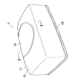
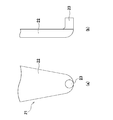
- FIG. 3A The perspective view of a one-touch opening and closing container. II-II sectional view taken on the line of FIG. 3A is a front view of the locking portion, and FIG. 3B is a side view of the locking portion.
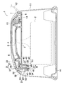
- the perspective view of the locking device accommodated in the locking device accommodation chamber. 6A is a front view of the locking device
- FIGS. 6B to 6D are a cross-sectional view taken along line AA, a cross-sectional view taken along line BB, and a cross-sectional view taken along line CC in FIG.
- FIGS. 7A to 7D are diagrams illustrating a process until the locking protrusion is locked
- FIGS. 7E to 7F are diagrams illustrating a process of releasing the locking protrusion.
- the figure showing the locking tool which concerns on 2nd Embodiment similarly to FIG. The figure showing the modification of an elastic element.
- the following embodiments relate to a one-touch open / close container having a push lock / open mechanism shown in the attached drawings, and include not only an indispensable structure of the invention but also a selective and preferable structure.
- a one-touch open / close container according to the present invention will be described by taking a wet tissue dispensing container 1 having a push lock / open mechanism as an example.
- the wet tissue dispensing container 1 includes a container body 11 and a lid 12, and the lid 12 is connected to the container body 11 via a hinge portion 14 so as to be pivotable. Yes.
- an elastic member 13 that biases the lid 12 in the opening direction is disposed.
- the elastic member 13 in the illustrated example is a folded rubber sheet piece.
- the container main body 11 has a casing 15 in which the extraction opening 3 is formed, a seal member 9 that covers a part of the extraction opening 3 and has a narrow opening 4 for taking out the wet tissue 2, and a narrow opening.
- the lid 12 in an opened state is partially omitted.
- the hinge portion 14 includes a rib 7 standing on the casing 15 and having a circular hole, and a pin 8 provided on the lid 12.
- the lid 12 is connected to the housing 15 so as to be able to turn. That is, the pivot axis of the lid 12 extends in a direction parallel to the extending direction of the pin 8 of the hinge portion 14.
- an engaging portion 21 that pivots around the pivot axis together with the lid 12 is provided upright. Yes.
- the locking portion 21 includes a locking protrusion 23 that can enter a locking device 40 described later.
- the housing 15 included in the container main body 11 is provided with a lock accommodation chamber 31 at a position facing the hinge portion 14 in a direction perpendicular to the extending direction of the pivot axis of the lid 12.
- the locking portion 21 includes a support column 22 standing on the lid 12 and a locking projection 23 protruding in a direction substantially perpendicular to the support column from the tip of the support column 22.
- the locking portion 21 is fixed to the lid 12.
- the shape of the locking projection 23 is not particularly limited, but it is preferable to use a cylindrical shape because engagement and disengagement with respect to the locking device 40 can be performed smoothly.
- the shape of the column portion 22 is not particularly limited, and can be a flat plate shape orthogonal to the protruding direction of the locking projection 23 or a semi-cylindrical shape with a semicircular cross-sectional shape.
- ribs can be provided to increase the rigidity of the column portion 22.
- the locking portion 21 can be integrated with or separate from the lid 12, and is preferably molded integrally with the lid 12 using a thermoplastic resin.
- an opening 32 is formed in the lock accommodation chamber 31 in which the lock 40 is accommodated.
- the opening 32 is disposed at a position facing the locking portion 21 provided on the back side of the lid 12 when the lid 12 is closed, and has a shape through which the locking portion 21 can pass.
- the lock tool 40 is housed in the lock tool storage chamber 31 so as to be slidable in a direction orthogonal to the entering direction Y of the locking projection 23.
- the sliding direction X of the locking device 40 is a direction orthogonal to the entering direction Y of the locking projection 23.
- the entering direction Y of the locking projection 23 is the vertical direction of the paper surface.
- the lock device accommodating chamber 31 includes an upper wall 33 having an opening 32 and a bottom wall 34 facing the upper wall 33, and a pair of first side wall portions facing each other in the sliding direction X of the lock device 40. 51 (see FIG. 4) and a second side wall 52 and a third side wall 53 extending between the pair of first side walls 51.
- the third side wall part 53 is located between the hinge part 14 and the second side wall part 52.
- locking part accommodation space 38 in which the latching
- the locking portion accommodation space 38 communicates with the opening 32.
- a continuous raised portion 37 for restricting the sliding direction X of the locking device 40 is disposed on each of the upper wall 33 and the bottom wall 34 of the locking device accommodating chamber 31.
- the continuous raised portion 37 extends with a certain width in a direction parallel to the sliding direction X of the locking device 40.
- two continuous raised portions 37 are disposed on the upper wall 33 of the lock device accommodating chamber 31, and one wider than the continuous raised portion 37 disposed on the upper wall 33 is disposed on the bottom wall 34.
- the continuous raised portion 37 is arranged.
- the locking device 40 has hemispherical protrusions 46 slidably contacting the continuous raised portion 37 on each of the surface facing the upper wall 33 and the surface facing the bottom wall 34.
- two protrusions 46 are disposed on the surface of the main body 49 of the locking device 40 that faces the upper wall 33 with a gap in the direction parallel to the sliding direction X of the locking device 40. It is located between two continuous raised portions 37 provided on the upper wall 33 of the storage chamber 31. As a result, the locking device 40 can be smoothly slid in a predetermined direction, and the locking device 40 is prevented from falling to the side of the engaging portion accommodating space 38 or the opposite side.
- a total of four protrusions 46 are provided on the surface of the lock device 40 facing the bottom wall 34 of the lock device storage chamber 31, that is, on the back side of the base portion 48, and provided on the bottom wall 34 of the lock device storage chamber 31.
- two protrusions 46 are slidably disposed on both side surfaces of the single continuous bulging portion 37.
- the locking device 40 can be smoothly slid in a predetermined direction, and further, the locking device 40 is prevented from moving out of the sliding direction X.
- the sliding direction X of the locking device 40 can be regulated, and the locking device 40 can fall down in the locking device storage chamber 31. It can prevent shifting.
- the first side wall 51 includes an accommodation groove 75 extending in the vertical direction between the upper wall 33 and the bottom wall 34.
- the accommodation groove 75 is a groove into which an elastic element 71 described later can enter.
- the housing groove 75 is a groove having a substantially rectangular cross-sectional shape that is recessed from the wall surface of the first side wall 51.
- a groove back surface 76 is located in the back of the housing groove 75 that is recessed from the wall surface of the first side wall 51 (in other words, the bottom of the housing groove 75).
- the illustration of the upper wall 33 and the second side wall portion 52 of the lock device accommodating chamber 31 is omitted for easy understanding.
- the locking device 40 slidably accommodated in the locking device storage chamber 31 includes a base portion 48 and a main body portion 49 extending orthogonally to the base portion 48. It is a mold member.
- the base portion 48 extends from the surface 47 of the main body portion 49 toward the locking portion accommodation space 38 and faces the bottom wall 34 of the lock device accommodation chamber 31 when housed in the lock device accommodation chamber 31.
- the main body portion 49 is plate-shaped, and the entrance / exit portion 41 through which the locking projection 23 of the locking portion 21 can enter and exit can be engaged with the surface 47 facing the locking portion accommodation space 38.
- An engaging portion 42 and a cam groove 43 that returns from the inlet / outlet portion 41 to the inlet / outlet portion 41 through the engaging portion 42 are formed.
- a part of the cam groove 43 is curved in a direction parallel to the sliding direction X of the lock tool 40.
- the engaging portion 42 is at a position facing the entrance / exit portion 41 in the approach direction Y of the locking projection 23.
- the opening dimension of the entrance / exit part 41 in the sliding direction X of the locking tool 40 gradually decreases toward the cam groove 43.
- at least a part of the entrance / exit 41 communicates with the opening 32 of the lock accommodation chamber 31. 4 to 6, the portions where the entrance / exit portion 41, the engaging portion 42, and the cam groove 43 are not arranged on the surface 47 of the locking device 40 are indicated by dots.
- the locking device 40 further includes a pair of elastic elements 71 extending from the side wall 45 in a direction parallel to the sliding direction X of the locking device 40.
- the elastic element 71 exhibits elasticity in at least a direction parallel to the sliding direction X of the locking device 40.
- the elastic element 71 of the present embodiment is a linear member shaped into a bent shape. More specifically, it is a linear resin shaped into a bent shape that can be deformed in a direction parallel to the sliding direction X of the locking device 40, and is molded integrally with the main body 49 of the locking device 40. Yes.
- the distal end portion 72 of the elastic element 71 enters the accommodation groove 75 and can contact the groove inner surface 76 of the accommodation groove 75.
- the elastic element 71 in contact with the accommodation groove 75 formed in the first side wall portion 51 is restrained from swaying the locking device 40, so that the generation of noise due to rattling of the locking device 40 is prevented.
- the cam groove 43 is a groove for guiding the locking projection 23 of the locking portion 21 in one direction from the entrance / exit portion 41 to the entrance / exit portion 41 through the engaging portion 42, and along the traveling direction of the locking projection 23. And a step portion in which the depth of the groove gradually decreases and a step portion in which the depth of the groove suddenly increases.
- the engaging portion 42 is disposed at a position facing the entrance / exit portion 41 in the approach direction Y of the locking projection 23 when the surface 47 of the locking device 40 is viewed from the front.
- the locking protrusion 23 of the locking portion 21 moves along the cam groove 43 so as to be pressed against the groove wall surface 44 of the cam groove 43.
- the depth of the cam groove 43 is determined in consideration of the fact that the locking projection 23 passes through the cam groove 43 while pivoting around the pivot axis of the lid 12. It is set to be pressed against the groove wall surface 44.
- at least the bottom surface of the engaging portion 42 and the cam groove 43 adjacent to the engaging portion 42 are included in the fan-like turning locus drawn by the entire locking projection 23 around the turning axis of the lid 12. A part of the groove wall surface 44 can be included.
- the cam groove 43 is divided into an entrance groove portion 61 extending from the entrance / exit portion 41 to the engagement portion 42 and an exit groove portion 62 returning from the engagement portion 42 to the entrance / exit portion 41. Then, the entrance groove portion 61 and the exit groove portion 62 merge at the entrance / exit portion 41. At the junction of the entrance groove 61 and the exit groove 62, the entrance groove 61 is deeper than the exit groove 62 (see FIGS. 6C and 6D).
- the entry groove 61 includes a first entry groove 61a starting from the entrance / exit 41, and a second entry groove 61b located between the first entry groove 61a and the engaging part 42. It is divided into and. As shown in FIG. 6B, the depth of the first entry groove 61a becomes gradually shallower toward the second entry groove 61b and suddenly becomes deep at the second entry groove 61b.
- the boundary between the first entry groove 61 a and the second entry groove 61 b is located at the curved portion 64 of the entry groove 61.
- the depth of the engaging part 42 is deeper than the entrance groove part 61 (FIGS. 6B and 6C). Therefore, the locking protrusion 23 does not return from the second entry groove 61b to the first entry groove 61a, and does not return from the engagement part 42 to the second entry groove 61b.
- the depth of the exit groove 62 is deeper than that of the engaging portion 42 (FIGS. 6C and 6D), and gradually becomes shallower toward the entrance / exit 41 through the curved portion 65 of the exit groove 62. Therefore, the locking protrusion 23 that has entered the exit groove 62 does not return to the engaging portion 42.
- FIG. 7 (a) to FIG. 7 (f) the support column 22 and the locking projection 23 are indicated by phantom lines, and the accommodation groove 75 is not shown.
- the lid 12 is closed. At this time, none of the pair of elastic elements 71 is deformed.
- the locking projection 23 falls from the engaging portion 42 into the withdrawal groove portion 62 as shown in FIG. Then, it moves to the curved portion 65 of the exit groove 62.
- the locking projection 23 reaches the curved portion 65 of the exit groove 62, the locking device 40 comes closest to the other of the pair of first side wall portions 51.
- the elastic element 71 on the left side of the paper surface escapes from the accommodation groove 75, and the elastic element 71 on the right side of the paper surface is deformed.
- the locking projection 23 is moved from the exit groove 62 to the entrance / exit 41 by the elastic force of the elastic member 13 that biases the lid 12 in the opening direction (FIG. 7 (f)). Further, it disengages from the locking device 40 (not shown). Thereby, the lid 12 is opened. At this time, none of the pair of elastic elements 71 is deformed, and the distal end portion 72 of each elastic element 71 is received in the receiving groove 75 and is in contact with the groove inner surface 76.
- the entrance / exit portion 41 of the locking device 40 faces the locking projection 23.
- the entrance / exit part 41 of the locking device 40 is in a position where the locking part 21 can enter.
- the position of the locking tool 40 can always be maintained at a position where the locking portion 21 can enter. In other words, it can be prevented that when the lid 12 is to be closed, the locking portion 21 is displaced from a position where the lid 21 can enter, and the lid 12 cannot be smoothly closed.
- FIG. 8 is a diagram showing the lock tool 40 housed in the lock tool storage chamber 31 in the same manner as FIG.
- the lid 12 is opened, that is, when the locking device 40 is not locked to the locking portion 21, the distal end portions 72 of the pair of elastic elements 71 are separated from the first side wall portion 51. ing. Therefore, when vibration in a direction parallel to the sliding direction X of the lock tool 40 is applied, the lock tool 40 can move in the lock tool storage chamber 31.
- the opening size of the inlet / outlet portion 41 in the sliding direction X of the locking device 40 gradually decreases toward the cam groove 43.
- the entrance / exit part 41 of the locking device 40 has a shape that narrows like a funnel.
- the doorway 41 of the locking device 40 has a shape that narrows in a funnel shape, so that the locking protrusion 23 of the locking portion 21 is formed in the doorway 41 of the locking device 40 as illustrated in FIG. Even when it is not located at the center of the lock, it is possible to allow the locking projection 23 to enter the entrance / exit 41 of the lock 40.
- the engaging projection 23 is connected to the entrance / exit portion 41 of the locking device 40.
- a locking projection center line P extending in a direction parallel to the entering direction Y of the locking projection 23 and passing through the center of the locking projection 23, and the locking projection 23 entering.
- the distance from the locking tool center line Q that extends in a direction parallel to the direction Y and passes through the center of the doorway 41 of the locking tool 40 is such that the locking protrusion 23 of the locking part 21 is located at the center of the doorway 41 of the locking tool 40. Even if it is not, it means that the locking projection 23 is within a range of distance that allows the locking projection 40 to enter the entrance / exit part 41.
- the pair of elastic elements 71 regulates the position of the entrance / exit portion 41 in the sliding direction X of the locking device 40 within a range in which the locking projection 23 of the locking portion 21 can enter.
- the entrance / exit portion 41 of the locking device 40 with respect to the engagement projection 23 required to make the engaging projection 23 enter the entrance / exit portion 41 of the locking device 40.
- the permissible tolerance of the position is ⁇ L 1 (for example, ⁇ 2 mm)
- the tip end portion of the elastic element 71 in a state where the locking projection center line P and the lock tool center line Q overlap (FIG. 8B).
- each of the two gaps 70 formed between 72 and the first side wall portion 51 is less than the allowable tolerance (for example, less than 2 mm)
- the position of the entrance / exit portion 41 in the sliding direction X of the locking device 40 is locked.
- the locking projection 23 of the portion 21 can be restricted to a range that can be entered.
- the locking device 40 comes closest to one of the pair of first side wall portions 51.
- the elastic element 71 is deformed most greatly.
- the tolerance of the position of the entrance / exit part 41 of the lock tool 40 with respect to the locking protrusion 23 is L 1 (mm)
- the side wall 45 of the lock tool 40 when the lock tool 40 is closest to the first side wall part 51 is L 2 (mm)
- the distance from the first side wall 51 is L 2 (mm)
- the value of L 1 can be made larger than L 2
- the entrance / exit 41 is always locked without using the elastic element 71.
- the protrusion 23 can be located at a position where it can enter.
- L 1 > L 2 it is difficult to make L 1 > L 2 .
- L 1 by increasing the distance of the inlet and outlet part 41 of the locking wing 40 in the entering direction Y parallel to the direction of the locking projection 23, it is possible to increase the L 1 by increasing the opening size of the inlet and outlet part 41.
- the length of the locking device 40 in the approach direction Y of the locking protrusion 23 is increased, and the overall length of the cam groove 43 is increased.
- the fluctuation range of the depth of the cam groove 43 is also increased.
- the overall design of 43 becomes difficult.
- L 2 can be relatively reduced, but it is difficult to ensure the strength of the locking projection 23.
- the movable range in the sliding direction X of the locking device 40 can be arbitrarily set without causing such a problem, so that the locking projection 23 enters the position of the entrance / exit portion 41. It can be easily restricted to possible positions.
- the elastic element 71 is locked from the pair of first side wall portions 51. Forty side walls 45 may be extended.
- the opening dimension of the entrance / exit part 41 in the sliding direction X of the lock tool 40 gradually decreases toward the cam groove 43, and from either the side wall 45 or the first side wall part 51 of the lock tool 40.
- the elastic element 71 extends toward one of the other, and a gap 70 is provided between the distal end portion 72 of the elastic element 71 and one of the side wall 45 and the first side wall portion 51 of the lock tool 40.
- the allowable tolerance of the position of the entrance / exit portion 41 of the lock tool 40 with respect to the lock projection 23 required to make the position of the entrance / exit portion 41 of the lock tool 40 a position where the lock projection 23 can enter in the sliding direction X of 40 When the dimension of the gap 70 between the distal end portion 72 of the elastic element 71 and one of the side wall 45 and the first side wall 51 of the locking device 40 is compared, the dimension of the gap 70 is larger than the allowable tolerance. It is small. Thereby, the position of the entrance / exit part 41 in the sliding direction X of the locking device 40 can be restricted to a range in which the locking projection 23 of the locking part 21 can enter.
- the locking device is used in the manufacturing process of the wet tissue dispensing container 1.
- the lock device 40 can be easily slid into the lock device storage chamber 31 from the supply magazine. Can be installed.
- the present invention is not limited to the first and second embodiments described above, and the shape and installation mode of the elastic element 71 can be variously changed.
- the elastic element 71 is integrated with the first side wall 51 of the lock device accommodating chamber 31 instead of the configuration in which the elastic element 71 is integrally formed with the lock device 40.
- the elastic element 71 is formed integrally with the first side wall 51, the housing groove 75 may or may not be provided on the side wall 45 of the lock tool 40.
- the elastic element 71 is formed integrally with either the side wall 45 of the lock tool 40 or the first side wall portion 51 of the lock tool storage chamber 31, the number of parts when the wet tissue dispensing container 1 is manufactured can be reduced. Can be reduced.
- the specific shape of the elastic element 71 is not particularly limited, and may be various shapes on the condition that the elastic element 71 exhibits elasticity in a direction parallel to the sliding direction X of the locking device 40.
- it can be a closed polygon as shown in FIGS. 9C and 9D, or a part of the side of the polygon is missing. It can also be an open polygon (not shown).
- resin or rubber metal can be appropriately selected and used.
- an elastic member such as a sponge or a coil spring (not shown) is used for the elastic element 71, so It can also be arranged between the one side wall 51 and the locking device 40.
- the elastic element 71 may be inserted only between the first side wall portion 51 of the lock device receiving chamber 31 and the lock device 40, or the elastic element 71 may be inserted between the side wall 45 of the lock device 40 and the first of the lock device receiving chamber 31. You may fix to either one or both of the 1 side wall part 51.
- the elastic element 71 When the elastic element 71 is inserted between the first side wall portion 51 of the lock device accommodating chamber 31 and the lock device 40, the manufacturing process of the wet tissue dispensing container 1 is simplified and the degree of freedom in design is increased.
- the elastic element 71 When the elastic element 71 is fixed to one or both of the side wall 45 of the lock tool 40 and the first side wall portion 51 of the lock tool storage chamber 31, the generation of abnormal noise due to the backlash of the elastic element 71 is prevented.
- the elastic element 71 may be in contact with both the lock tool 40 and the first side wall 51 of the lock tool storage chamber 31, or the first side wall of the lock tool 40 and the lock tool storage chamber 31. Only one of 51 may be in contact.
- the lock tool 40 may be disposed on the lid 12 side.
- the sliding direction X of the locking tool 40 is a direction parallel to the turning axis of the lid 12
- the sliding direction X of the locking tool 40 is not limited to this.
- the lid 12 can be slid in a direction orthogonal to or intersecting with the extending direction of the pivot axis.
- the locking tool 40 combining the concave groove
- a thermoplastic resin, a metal, and a thermoplastic elastomer can be appropriately selected and used as long as there is no particular limitation.
- the terms “first”, “second”, and “third” are used to distinguish similar elements, positions, and the like.
Landscapes
- Engineering & Computer Science (AREA)
- Mechanical Engineering (AREA)
- Closures For Containers (AREA)
Abstract
改良されたプッシュロック・オープン機構を備えるワンタッチ開閉容器の提供。 取出開口(3)を有する容器本体(11)と、取出開口を開閉可能な上蓋(12)と、上蓋を開閉可能なプッシュロック・オープン機構とを備えるワンタッチ開閉容器(1)であって、プッシュロック・オープン機構に、上蓋と容器本体のいずれか一方に立設される係止部(21)と、上蓋と容器本体の他方に配置されるロック具(40)及びロック具収容室(31)とが含まれ、係止部の先端が係止突起(23)を備え、ロック具の表面に、係止突起の出入口部(41)及び係合部(42)と、出入口部から係合部を経て出入口部に戻るカム溝(43)とが形成され、ロック具が、ロック具収容室内に係止突起の進入方向に直交する方向に摺動可能に収められ、ロック具の摺動方向において対向するロック具収容室の側壁部(51)とロック具の側壁(45)との間に、弾性要素(71)が配置される。
Description
本願は、ワンタッチ開閉容器に関する。
従来、蓋を押すだけで開閉可能なプッシュロック・オープン機構を備えるワンタッチ開閉容器は公知である。例えば特許文献1には、内容物取り出し用の取出し口を備えた容器部と、該容器部の取出し口を閉じるように容器部にヒンジ手段を介して揺動自在に連結された蓋と、該蓋を開方向に付勢するばね手段と、蓋の先端領域を容器部に押し付けるように押すことで蓋の先端領域を容器部にロックし、ロック状態にある蓋の先端領域を再度押すことでロックを解除する構成のプッシュロック・オープン機構を有するワンタッチ開閉容器が開示されている。
特許文献1の図1~13には、円環状ラチェット歯を用いたプッシュロック・オープン機構が開示され、図14~16には回転駒を用いたプッシュロック・オープン機構が開示されている。しかし、円環状ラチェット歯及び回転駒は、蓋を開閉するとき回転する部材であり、円環状ラチェット歯及び回転駒が回転する空間を確保する必要があるので、プッシュロック・オープン機構の容積が大きくなってしまう。このため、ワンタッチ開閉容器内に物品を収めるための空間が狭くなるという問題がある。特許文献1にはさらに、ヒンジ部を中心として揺動可能なカム部材と、カム溝が形成された溝カム板とを用いたプッシュロック・オープン機構が開示されている(図17~21参照)。カム部材と溝カム板を用いたプッシュロック・オープン機構の場合、回転部材は不要なので、ワンタッチ開閉容器内に物品を収めるための空間が狭くなるという問題は回避できる。しかし、蓋の開閉を繰り返すと、カム部材がヒンジ部で折損することがある。カム部材の折損を防ぐために、カム部材を固定し溝カム板を移動可能にすることが考えられる。しかし、溝カム板を移動可能にすると、溝カム板がカム部材に係止されていないとき、すなわち蓋が開放されているときに溝カム板がズレ動いてカム部材との係合位置からズレてしまい、蓋を閉めようとしたときうまく閉まらなくなるという問題が生じる。公知のプッシュロック・オープン機構には以上のような問題があり、さらに改良が求められている。
本発明は、改良されたプッシュロック・オープン機構を備えるワンタッチ開閉容器を提供することを課題とする。
本発明は、上面に取出開口を有する容器本体と、容器本体の上面にヒンジ部を介して取り付けられ、取出開口を開閉可能な上蓋と、上蓋を押すことで上蓋を開閉可能なプッシュロック・オープン機構とを備え、プッシュロック・オープン機構がヒンジ部から離間する位置に配置されるワンタッチ開閉容器に関する。
本発明のワンタッチ開閉容器は、プッシュロック・オープン機構に、上蓋と容器本体とのいずれか一方に立設される係止部と、上蓋と容器本体とのいずれか他方に配置されるロック具及びロック具収容室とが含まれ、係止部の先端に係止突起が備えられ、ロック具の表面に、係止突起が進入及び退出可能な出入口部と、係止突起が係合可能な係合部と、出入口部から係合部を経て出入口部に戻るカム溝とが形成され、ロック具収容室が、係止部が通過可能な開口部を有しており、上蓋を閉じたとき係止突起がロック具に係合し、ロック具が、ロック具収容室内に、係止突起の進入方向に対し直交する方向に摺動可能に収められるとともに、カム溝がロック具の摺動方向に並行な方向に湾曲し、さらに、ロック具の摺動方向において互いに対向するロック具収容室の側壁部とロック具の側壁との間に、ロック具の摺動方向に弾性変形可能な弾性要素が配置される。本発明のワンタッチ開閉容器では、プッシュロック・オープン機構の係止部を固定し、係止部が進入するロック具をロック具収容室内で摺動させるので、蓋の開閉を繰り返しても、係止部が折損することは無い。さらに、ロック具の摺動方向に弾性変形可能な弾性要素を配置しているので、ロック具の摺動可能範囲が規制される結果、ロック具は常に係止部が進入可能な位置に保たれる。これにより改良されたプッシュロック・オープン機構を備えるワンタッチ開閉容器が提供される。
1つの実施形態に係る発明では、弾性要素が、ロック具の側壁及びロック具収容室の側壁部のいずれか一方と一体に形成される。これにより、ワンタッチ開閉容器の部品点数が削減される。
1つの実施形態に係る発明では、弾性要素が、ロック具の側壁及びロック具収容室の側壁部のいずれか一方と一体に形成され、ロック具の側壁及びロック具収容室の側壁部のいずれか他方に、弾性要素が進入可能な収容溝を備える。これにより、ロック具のがたつきによる異音発生が防止される。
1つの実施形態に係る発明では、弾性要素が、ロック具と、ロック具収容室の側壁部との間に挿入され、ロック具の側壁及びロック具収容室の側壁部のいずれか一方又は両方に、弾性要素が固定される。これにより、ワンタッチ開閉容器の製造工程が簡略化され、設計の自由度が増す。
1つの実施形態に係る発明では、弾性要素が、ロック具と、ロック具収容室の側壁部との間に挿入され、ロック具の側壁及びロック具収容室の側壁部のいずれか一方又は両方に、弾性要素が固定される。これにより、弾性要素のがたつきによる異音発生が防止される。
1つの実施形態に係る発明では、ロック具の摺動方向における出入口部の開口寸法がカム溝に向かうに従い次第に減少し、ロック具の側壁及びロック具収容室の側壁部のいずれか一方からいずれか他方に向けて弾性要素が延出し、弾性要素の先端部分と、ロック具の側壁及びロック具収容室の側壁部のいずれか一方との間に隙間が設けられ、隙間の寸法と、ロック具の摺動方向においてロック具の出入口部の位置を係止突起が進入可能な位置にするために必要な係止突起に対するロック具の出入口部の位置の許容公差とを比較したとき、許容公差よりも隙間の寸法の方が小さい。これにより、ロック具の摺動方向における出入口部の位置を、係止部の係止突起が進入可能な範囲に規制することができる。
本発明に係る一つ以上の実施形態によれば、改良されたプッシュロック・オープン機構を備えるワンタッチ開閉容器、例えば、ウェットティシュ等の分与容器が提供される。
図面は、本発明の特定の実施の形態を示し、発明の不可欠な構成ばかりでなく、選択的及び好ましい実施の形態を含む。
ワンタッチ開閉容器の斜視図。
図1のII-II線断面図。
図3(a)は係止部の正面図、図3(b)は係止部の側面図。
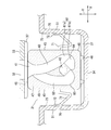
ロック具収容室内に収められたロック具を図2のIV-IV線切断面から見た矢視図。
ロック具収容室内に収められたロック具の斜視図。
図6(a)はロック具の正面図、図6(b)~(d)はそれぞれ、図6(a)のA-A線断面図、B-B線断面図、C-C断面図。
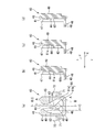
図7(a)~(d)は係止突起を係止するまでの過程を表す図、図7(e)~(f)は係止突起の係止を解除する過程を表す図。
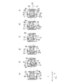
第2実施形態に係るロック具を図4と同様にして表す図。
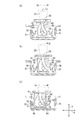
弾性要素の変形例を表す図。
下記の実施の形態は添付の図面に示すプッシュロック・オープン機構を備えるワンタッチ開閉容器に関し、発明の不可欠な構成ばかりではなく、選択的及び好ましい構成を含む。以下、添付の図面を参照して、本発明に係るワンタッチ開閉容器について、プッシュロック・オープン機構を備えるウェットティシュ分与容器1を例に説明する。
<第1実施形態>
図1及び図2に示すように、ウェットティシュ分与容器1は、容器本体11と、蓋12とを備え、蓋12はヒンジ部14を介して容器本体11に対し旋回動可能に連結されている。容器本体11と蓋12との間のヒンジ部14近傍には、蓋12を開く方向に付勢する弾性部材13が配置されている。図示例の弾性部材13は、折り畳まれたゴムシート片である。容器本体11には、取出開口3が形成された筐体15と、取出開口3の一部を覆うとともにウェットティシュ2を取り出すための狭開口部4が形成されたシール部材9と、狭開口部4より開口面積が大きい補助開口5が形成されたシール押さえ部材6と、筐体15の底部に嵌め合わされる底蓋16とが含まれる。ウェットティシュ2は、筐体15と底蓋16との間に形成される空間内に収められ、取出開口3、狭開口部4、及び補助開口5を通して取り出される。なお、図2では開放された状態の蓋12の図示を一部省略している。
図1及び図2に示すように、ウェットティシュ分与容器1は、容器本体11と、蓋12とを備え、蓋12はヒンジ部14を介して容器本体11に対し旋回動可能に連結されている。容器本体11と蓋12との間のヒンジ部14近傍には、蓋12を開く方向に付勢する弾性部材13が配置されている。図示例の弾性部材13は、折り畳まれたゴムシート片である。容器本体11には、取出開口3が形成された筐体15と、取出開口3の一部を覆うとともにウェットティシュ2を取り出すための狭開口部4が形成されたシール部材9と、狭開口部4より開口面積が大きい補助開口5が形成されたシール押さえ部材6と、筐体15の底部に嵌め合わされる底蓋16とが含まれる。ウェットティシュ2は、筐体15と底蓋16との間に形成される空間内に収められ、取出開口3、狭開口部4、及び補助開口5を通して取り出される。なお、図2では開放された状態の蓋12の図示を一部省略している。
ヒンジ部14には筐体15に立設され円形孔が形成されたリブ7と、蓋12に設けられるピン8とが含まれ、リブ7の円形孔に蓋12のピン8を挿入することにより、蓋12が筐体15に対し旋回動可能に連結されている。すなわち、蓋12の旋回軸は、ヒンジ部14のピン8の延在方向に平行な方向に延びる。蓋12の旋回軸の延在方向に直交する方向においてヒンジ部14から離間する蓋12の端部の裏側には、蓋12とともに旋回軸の周囲を旋回動する係止部21が立設されている。係止部21は、後述するロック具40に進入可能な係止突起23を備える。また、容器本体11に含まれる筐体15には、蓋12の旋回軸の延在方向に直交する方向においてヒンジ部14に離間対向する位置に、ロック具収容室31が配置されている。
図3に示すように、係止部21は蓋12に立設される支柱部22と、支柱部22の先端部から支柱部にほぼ直交する方向に突き出す係止突起23とを備える。係止部21は蓋12に対し固定されている。係止突起23の形状は特に限定されないが、円柱状にすれば、ロック具40に対する係合及び離脱が円滑に行われるので好ましい。支柱部22の形状も特に限定されず、例えば係止突起23の突出方向に直交する平板形状、または断面形状が半円状の半円柱状にすることができる。また、支柱部22の剛性を増すためにリブを設けることもできる。係止部21は、蓋12と一体または別体とすることができ、熱可塑性樹脂を用いて蓋12と一体に成形することが好ましい。
図2と図4に示すように、ロック具40が収められるロック具収容室31には、開口部32が形成されている。開口部32は、蓋12を閉じたとき蓋12の裏側に設けられた係止部21に対向する位置に配置され、係止部21が通過可能な形状を有する。ロック具40は、ロック具収容室31の中に、係止突起23の進入方向Yに対し直交する方向に摺動可能に収められる。ここで、ロック具40の摺動方向Xは、係止突起23の進入方向Yに直交する方向であり、図4では、係止突起23の進入方向Yは紙面縦方向であり、ロック具40の摺動方向Xは紙面横方向である。
ロック具収容室31は、開口部32を有する上部壁33と、上部壁33に対向する底部壁34とを備え、さらに、ロック具40の摺動方向Xにおいて互いに対向する一対の第1側壁部51(図4参照)と、一対の第1側壁部51の間に延びる第2側壁部52及び第3側壁部53を備える。第3側壁部53は、ヒンジ部14と第2側壁部52との間に位置する。ロック具収容室31の第2側壁部52とロック具40との間には、係止部21が進入及び退出可能な係止部収容空間38が形成される。係止部収容空間38は、開口部32に連通する。
図2及び図4に示すように、ロック具収容室31の上部壁33及び底部壁34それぞれに、ロック具40の摺動方向Xを規制するための連続隆起部37が配置されている。連続隆起部37は、ロック具40の摺動方向Xと平行な方向に一定の幅で延びる。本実施形態では、ロック具収容室31の上部壁33には2条の連続隆起部37が配置され、底部壁34には、上部壁33に配置された連続隆起部37よりも幅広の1条の連続隆起部37が配置されている。また、ロック具40は、上部壁33に対向する面及び底部壁34に対向する面のそれぞれに、連続隆起部37に摺動可能に接触する半球状の突起部46を有する。
詳しくは、ロック具40の本体部49において上部壁33に対向する面には、2つの突起部46が、ロック具40の摺動方向Xと平行な方向に間隔を開けて配置され、ロック具収容室31の上部壁33に設けられた2条の連続隆起部37の間に位置している。これにより、ロック具40を所定の方向に円滑に摺動させることができ、さらに、ロック具40が係止部収容空間38側、またはその反対側に倒れることが防止される。また、ロック具40がロック具収容室31の底部壁34に対向する面、すなわちベース部48の裏側には合計4つの突起部46が設けられ、ロック具収容室31の底部壁34に設けられた1条の連続隆起部37の両側面のそれぞれに突起部46が2つずつ摺動可能に接するように配置されている。これにより、ロック具40を所定の方向に円滑に摺動させることができ、さらに、ロック具40が摺動方向Xから逸れてずれ動くことが防止される。以上の説明から明らかなように、連続隆起部37及び突起部46を配置することにより、ロック具40の摺動方向Xを規制できるとともに、ロック具40がロック具収容室31内で転倒したりずれ動いたりすることを防止できる。
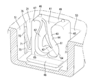
図4,5に示すように、第1側壁部51は、上部壁33と底部壁34との間を上下方向に延びる収容溝75を備える。収容溝75は、後述する弾性要素71が進入可能な溝である。収容溝75は、第1側壁部51の壁面から凹状に窪んだ断面形状がほぼ矩形の溝である。第1側壁部51の壁面から凹状に窪む収容溝75の奥(別言すれば収容溝75の底)には、溝奥面76が位置する。なお、図5では理解を容易にするために、ロック具収容室31の上部壁33と第2側壁部52の図示を省略している。
図4~6に示すように、ロック具収容室31に摺動可能に収められるロック具40は、ベース部48と、ベース部48に直交して延出する本体部49とを備える略L字型の部材である。ベース部48は、本体部49の表面47から係止部収容空間38側に向けて延出し、ロック具収容室31に収められたとき、ロック具収容室31の底部壁34に対向する。本体部49は板状であり、係止部収容空間38に対向する表面47に、係止部21の係止突起23が進入及び退出可能な出入口部41と、係止突起23が係合可能な係合部42と、出入口部41から係合部42を経て出入口部41に戻るカム溝43が形成されている。カム溝43の一部は、ロック具40の摺動方向Xと並行な方向に湾曲している。ロック具40を正面から見たとき、係合部42は、係止突起23の進入方向Yにおいて出入口部41に対向する位置にある。ロック具40の摺動方向Xにおける出入口部41の開口寸法は、カム溝43に向かうに従い次第に小さくなっている。また、出入口部41の少なくとも一部がロック具収容室31の開口部32に連通する。なお、図4~6では、ロック具40の表面47に出入口部41、係合部42、及びカム溝43が配置されていない部分を、ドットを付して表している。
ロック具40はさらに、側壁45からロック具40の摺動方向Xと平行な方向に延出する一対の弾性要素71を備える。弾性要素71は、少なくともロック具40の摺動方向Xと平行な方向に弾性を示す。本実施形態の弾性要素71は、屈曲した形状に賦形された線状の部材である。より具体的には、ロック具40の摺動方向Xと平行な方向に変形可能な屈曲した形状に賦形された線状の樹脂であり、ロック具40の本体部49と一体に成形されている。本実施形態では、弾性要素71の先端部分72は収容溝75に進入して収容溝75の溝奥面76に接触可能である。これにより、第1側壁部51に形成された収容溝75に接触する弾性要素71によりロック具40が揺れ動くことが抑制される結果、ロック具40のがたつきによる異音発生が防止される。
次に、図6を参照して、ロック具40の表面47に配置された出入口部41、係合部42、及びカム溝43について説明する。カム溝43は、係止部21の係止突起23を、出入口部41から係合部42を経て出入口部41へ一方向に誘導するための溝であり、係止突起23の進行方向に沿って溝の深さが徐々に浅くなる部分と、溝の深さが突然深くなる段差部とを有する。前述のように、係合部42は、ロック具40の表面47を正面から見たとき、係止突起23の進入方向Yにおいて出入口部41に対向する位置に配置される。また、係止部21の係止突起23は、カム溝43の溝壁面44に押し付けられるようにしてカム溝43に沿って移動する。ここで、カム溝43の深さは、係止突起23が蓋12の旋回軸の周囲を旋回動しながらカム溝43を通過することを考慮に入れて、係止突起23がカム溝43の溝壁面44に押し付けられるように設定される。例えば、本実施形態では、蓋12の旋回軸を中心として係止突起23全体が描く扇状の旋回軌跡の中に、少なくとも係合部42の底面と、係合部42に隣接するカム溝43の溝壁面44の一部とが含まれるようにすることができる。
図6(a)~(d)に示すように、カム溝43は、出入口部41から係合部42に至る進入溝部61と、係合部42から出入口部41に戻る退出溝部62とに区分され、進入溝部61と退出溝部62は、出入口部41において合流する。進入溝部61と退出溝部62との合流点では、退出溝部62よりも進入溝部61の方が深くなっている(図6(c),(d)参照)。このように、出入口部41において合流する進入溝部61と退出溝部62との間に段差があることにより、出入口部41から進入した係止部21の係止突起23は、進入溝部61へ誘導される。図6(a)に示すように、進入溝部61は、出入口部41から出発する第1進入溝部61aと、第1進入溝部61aと係合部42との間に位置するする第2進入溝部61bとに区分される。図6(b)に示すように、第1進入溝部61aの深さは第2進入溝部61bに向かうに従い次第に浅くなり、第2進入溝部61bで急に深くなる。第1進入溝部61aと第2進入溝部61bとの境界は、進入溝部61の湾曲部64に位置する。また、係合部42の深さは進入溝部61よりも深くなっている(図6(b),(c))。したがって、係止突起23が第2進入溝部61bから第1進入溝部61aへ逆戻りすることは無く、また係合部42から第2進入溝部61bへ逆戻りすることもない。退出溝部62の深さは係合部42よりもさらに深くなっており(図6(c),(d))、退出溝部62の湾曲部65を経て出入口部41に向かうに従い次第に浅くなる。したがって、退出溝部62へ進入した係止突起23が係合部42へ逆戻りすることは無い。
図7を参照して、本発明のプッシュロック・オープン機構の動作を説明する。なお、図面を見やすくするため、図7(a)~(f)では支柱部22及び係止突起23を仮想線で示し、収容溝75の図示は省略している。
蓋12(図示せず)を閉じるために蓋12を押し下げると、図7(a)に示すように、係止部21の係止突起23がロック具40の出入口部41に進入し、さらにカム溝43の第1及び第2進入溝部61a,61bに沿って移動する。このとき、ロック具40の表面47の正面視において、係止突起23は直線的に移動する。このため、図7(b)に示すように、ロック具40は摺動規制部である連続隆起部37の延在方向に沿って、図示例では紙面左方向に摺動する。このとき、紙面左側の弾性要素71は変形し、紙面右側の弾性要素71は収容溝75から脱出する。図7(c)に示すように、係止突起23が進入溝部61の湾曲部64を通過するとき、ロック具40は一対の第1側壁部51の内の一方に最も接近する。また、前述のように係止突起23はカム溝43の溝壁面44に押し付けられている。このため、湾曲部64を通過した係止突起23は、第1進入溝部61aよりも深さが大きい第2進入溝部61bに落ち込む(図示せず)。この時点で蓋12から手を放すと、蓋12は弾性部材13(図示せず)により開く方向へ付勢されているので、図7(d)に示すように係止突起23は出入口部41に向かう方向に動き、第2進入溝部61bからさらに係合部42へ落ち込んで係止される。これにより、蓋12が閉止される。このとき、一対の弾性要素71はいずれも変形していない。蓋12を開けるために、蓋12を弾性部材13の弾性力に抗して手で押し下げると、図7(e)に示すように、係止突起23は係合部42から退出溝部62へ落ち込んで、退出溝部62の湾曲部65へ移動する。係止突起23が退出溝部62の湾曲部65に達したとき、ロック具40は一対の第1側壁部51の内の他方に最も接近する。このとき、紙面左側の弾性要素71は収容溝75から脱出し、紙面右側の弾性要素71は変形する。その後、蓋12から手を放すと、蓋12を開く方向に付勢する弾性部材13の弾性力により、係止突起23が退出溝部62から出入口部41へ移動し(図7(f))、さらにロック具40から離脱する(図示せず)。これにより、蓋12が開放される。このとき、一対の弾性要素71はいずれも変形しておらず、各弾性要素71の先端部分72は収容溝75に収容され溝奥面76に接触している。
蓋12を開放したとき、ロック具40の出入口部41は係止突起23に正対する。別言すれば、ロック具40の出入口部41は係止部21が進入可能な位置にある。上記のように、蓋12が開放された状態のとき、一対の弾性要素71はいずれも変形しておらず、弾性要素71の先端部分72は収容溝75に収容され溝奥面76に接触している。したがって、蓋12が開放された状態でロック具40の摺動方向Xと平行な方向の振動が加えられたときでも、弾性要素71により、ロック具40がロック具収容室31内で移動することが防止される。これにより、ロック具40の位置を、常に係止部21が進入可能な位置に維持することができる。別言すれば、蓋12を閉じようとしたときに係止部21が進入可能な位置からズレてしまい、蓋12の閉止操作を円滑に行えなくなることを防止できる。
<第2実施形態>
本実施形態は、第1側壁部51に収容溝75が配置されていない点、及び、蓋12を開放した状態のとき、一対の弾性要素71の先端部分72が第1側壁部51に接触しない点で第1実施形態と相違する。残余の構成は第1実施形態と同一なので、詳しい説明は省略する。
本実施形態は、第1側壁部51に収容溝75が配置されていない点、及び、蓋12を開放した状態のとき、一対の弾性要素71の先端部分72が第1側壁部51に接触しない点で第1実施形態と相違する。残余の構成は第1実施形態と同一なので、詳しい説明は省略する。
図8は、図4と同様にしてロック具収容室31内に収められたロック具40を表す図である。本実施形態では、蓋12を開放した状態のとき、すなわち、ロック具40が係止部21に係止されていないとき、一対の弾性要素71の先端部分72が第1側壁部51から離間している。したがって、ロック具40の摺動方向Xと平行な方向の振動が加えられたとき、ロック具40はロック具収容室31内で移動し得る。ここで、第1実施形態と同様に、本実施形態でもロック具40の摺動方向Xにおける出入口部41の開口寸法は、カム溝43に向かうに従い次第に小さくなっている。別言すれば、ロック具40の出入口部41は、漏斗状に狭まる形状を有する。このように、ロック具40の出入口部41が漏斗状に狭まる形状を有することにより、図8(a)に例示するように、係止部21の係止突起23がロック具40の出入口部41の中央に位置していない場合でも、係止突起23をロック具40の出入口部41に進入させることが可能である。
すなわち、ロック具40の摺動方向Xにおいて、係止突起23に対するロック具40の出入口部41の位置が一定の許容公差の範囲内であれば、係止突起23をロック具40の出入口部41に進入させることができる。なお、本発明で許容公差の範囲内というときは、係止突起23の進入方向Yと平行な方向に延び係止突起23の中心を通る係止突起中心線Pと、係止突起23の進入方向Yと平行な方向に延びロック具40の出入口部41の中央を通るロック具中心線Qとの距離が、係止部21の係止突起23がロック具40の出入口部41の中央に位置していない場合でも、係止突起23をロック具40の出入口部41に進入させることが可能な距離の範囲内にあることを意味する。
本実施形態では、一対の弾性要素71により、ロック具40の摺動方向Xにおける出入口部41の位置を、係止部21の係止突起23が進入可能な範囲に規制している。図8(a),(b)を参照して、係止突起23をロック具40の出入口部41に進入可能な位置にするために要求される係止突起23に対するロック具40の出入口部41の位置の許容公差を±L1(例えば±2mm)としたとき、係止突起中心線Pとロック具中心線Qとが重なった状態(図8(b))において、弾性要素71の先端部分72と第1側壁部51との間にできる2つの隙間70それぞれの寸法を許容公差未満(例えば2mm未満)にすれば、ロック具40の摺動方向Xにおける出入口部41の位置を、係止部21の係止突起23が進入可能な範囲に規制することができる。
前述のように、係止突起23が進入溝部61の湾曲部64を通過するとき、ロック具40は一対の第1側壁部51の内の一方に最も接近する。このとき、図8(c)に示すように、弾性要素71は最も大きく変形する。ここで、係止突起23に対するロック具40の出入口部41の位置の許容公差をL1(mm)とし、ロック具40が第1側壁部51に最も接近したときのロック具40の側壁45と第1側壁部51との距離をL2(mm)としたとき、L1の値をL2よりも大きくすることが可能なら、弾性要素71を用いるまでもなく、出入口部41を常に係止突起23が進入可能な位置に位置させることができる。
しかしL1>L2にするのは困難である。例えば、係止突起23の進入方向Yと平行な方向におけるロック具40の出入口部41の距離を大きくすれば、出入口部41の開口寸法を大きくしてL1を大きくすることができる。しかし、この方法では、係止突起23の進入方向Yにおけるロック具40の長さが大きくなり、カム溝43の全長が増大する結果、カム溝43の深さの変動幅も大きくなり、カム溝43全体の設計が困難になる。また、係止突起23の太さを小さくすれば、L2を相対的に小さくできるが、係止突起23の強度を確保することが困難になる。しかし、弾性要素71を用いれば、このような問題を生じることなくロック具40の摺動方向Xにおける可動範囲を任意に設定することができるので、出入口部41の位置を係止突起23が進入可能な位置に容易に規制することができる。
上記では、一対の弾性要素71がロック具40の側壁45それぞれから第1側壁部51に向けて延出している場合について説明したが、弾性要素71は一対の第1側壁部51それぞれからロック具40の側壁45に向けて延出していてもよい。
すなわち本実施形態では、ロック具40の摺動方向Xにおける出入口部41の開口寸法が、カム溝43に向かうに従い次第に減少し、ロック具40の側壁45及び第1側壁部51のいずれか一方からいずれか他方に向けて弾性要素71が延出し、弾性要素71の先端部分72と、ロック具40の側壁45及び第1側壁部51のいずれか一方との間に隙間70が設けられ、ロック具40の摺動方向Xにおいてロック具40の出入口部41の位置を係止突起23が進入可能な位置にするために必要な係止突起23に対するロック具40の出入口部41の位置の許容公差と、弾性要素71の先端部分72と、ロック具40の側壁45及び第1側壁部51のいずれか一方との間の隙間70の寸法とを比較したとき、許容公差よりも隙間70の寸法の方が小さい。これにより、ロック具40の摺動方向Xにおける出入口部41の位置を、係止部21の係止突起23が進入可能な範囲に規制することができる。さらに、弾性要素71の先端部分72と、ロック具40の側壁45及び第1側壁部51のいずれか一方との間に隙間70を設ければ、ウェットティシュ分与容器1の製造工程においてロック具40をロック具収容室31内に設置する際、ロック具40をロック具収容室31内に押し込む必要は無く、例えばロック具40を供給マガジンからロック具収容室31内へ滑落させるだけで容易に設置することができる。
本発明は上記の第1及び第2実施形態に限定されず、弾性要素71の形状及び設置態様等を種々変更することができる。例えば、図9(a),(b)に示すように、弾性要素71をロック具40と一体に成形する構成に代えて、弾性要素71をロック具収容室31の第1側壁部51と一体に成形することができる。弾性要素71を第1側壁部51と一体に成形する場合、ロック具40の側壁45に収容溝75を設けてもよいし、設けなくてもよい。このように弾性要素71をロック具40の側壁45及びロック具収容室31の第1側壁部51のいずれか一方と一体に形成すれば、ウェットティシュ分与容器1を製造する際の部品点数を削減することができる。
弾性要素71の具体的形状は特に限定されず、ロック具40の摺動方向Xと平行な方向において弾性を示すことを条件に、種々の形状にすることができる。例えば、弾性要素71の形状を屈曲した線状とする代わりに、図9(c),(d)に示すような閉じた多角形にすることもできるし、多角形の辺の一部が欠落した開いた多角形(図示せず)にすることもできる。なお、弾性要素71の素材には、樹脂、ゴム金属を適宜選択して用いることができる。
別の変形例として、図9(e),(f)に示すように、スポンジやコイルばね(図示せず)等の弾性を示す部材を弾性要素71に用いて、ロック具収容室31の第1側壁部51と、ロック具40との間に配置することもできる。この場合、弾性要素71はロック具収容室31の第1側壁部51と、ロック具40との間に挿入されているだけでもよいし、ロック具40の側壁45及びロック具収容室31の第1側壁部51のいずれか一方または両方に固定してもよい。弾性要素71をロック具収容室31の第1側壁部51と、ロック具40との間に挿入する場合、ウェットティシュ分与容器1の製造工程が簡略化され、設計の自由度が増す。弾性要素71をロック具40の側壁45及びロック具収容室31の第1側壁部51のいずれか一方または両方に固定する場合、弾性要素71のがたつきによる異音発生が防止される。いずれの場合においても、弾性要素71がロック具40及びロック具収容室31の第1側壁部51の両方に接触していてもよいし、ロック具40及びロック具収容室31の第1側壁部51のいずれか一方のみに接触していてもよい。
第1及び第2実施形態では、ロック具40を容器本体11側に配置する例について説明したが、ロック具40を蓋12側に配置することもできる。また、ロック具40の摺動方向Xが蓋12の旋回軸に平行な方向である場合を例に説明したが、ロック具40の摺動方向Xはこれに限定されず、例えばロック具40を蓋12の旋回軸の延在方向に対し直交または交差する方向に摺動させることもできる。また、連続隆起部37と突起部46とを組み合わせてロック具40の摺動を規制する例について説明したが、断面が台形の凹状溝と断面が台形の凸堤部とを組合せてロック具40の摺動を規制することもできる。本発明のワンタッチ開閉容器の製造に用いる材料には、特に限定の無い限り、熱可塑性樹脂、金属、熱可塑性エラストマーを適宜選択して用いることができる。本願の明細書及び特許請求の範囲において、用語「第1」「第2」「第3」は、同様の要素、位置等を区別するために用いられている。
1 ワンタッチ開閉容器(ウェットティシュ分与容器)
11 容器本体
12 蓋
13 弾性部材
14 ヒンジ部
15 筐体
21 係止部
22 支柱部
23 係止突起
31 ロック具収容室
32 開口部
33 上部壁
34 底部壁
40 ロック具
41 出入口部
42 係合部
43 カム溝
44 カム溝の溝壁面
45 ロック具の側壁
47 表面
51 ロック具収容室の側壁部(第1側壁部)
70 隙間
71 弾性要素
72 先端部分
X 摺動方向
Y 係止突起の進入方向
P 係止突起中心線
Q ロック具中心線
11 容器本体
12 蓋
13 弾性部材
14 ヒンジ部
15 筐体
21 係止部
22 支柱部
23 係止突起
31 ロック具収容室
32 開口部
33 上部壁
34 底部壁
40 ロック具
41 出入口部
42 係合部
43 カム溝
44 カム溝の溝壁面
45 ロック具の側壁
47 表面
51 ロック具収容室の側壁部(第1側壁部)
70 隙間
71 弾性要素
72 先端部分
X 摺動方向
Y 係止突起の進入方向
P 係止突起中心線
Q ロック具中心線
Claims (6)
- 上面に取出開口を有する容器本体と、
前記容器本体の前記上面にヒンジ部を介して取り付けられ、前記取出開口を開閉可能な上蓋と、
前記上蓋を押すことで前記上蓋を開閉可能なプッシュロック・オープン機構とを備え、
前記プッシュロック・オープン機構が前記ヒンジ部から離間する位置に配置されるワンタッチ開閉容器であって、
前記プッシュロック・オープン機構に、
前記上蓋と前記容器本体とのいずれか一方に立設される係止部と、
前記上蓋と前記容器本体とのいずれか他方に配置されるロック具及びロック具収容室とが含まれ、
前記係止部の先端に係止突起が備えられ、
前記ロック具の表面に、前記係止突起が進入及び退出可能な出入口部と、前記係止突起が係合可能な係合部と、前記出入口部から前記係合部を経て前記出入口部に戻るカム溝とが形成され、
前記ロック具収容室が、前記係止部が通過可能な開口部を有しており、前記上蓋を閉じたとき前記係止突起が前記ロック具に係合し、
前記ロック具が、前記ロック具収容室内に、前記係止突起の進入方向に対し直交する方向に摺動可能に収められるとともに、前記カム溝が前記ロック具の摺動方向に並行な方向に湾曲し、
さらに、前記ロック具の摺動方向において互いに対向する前記ロック具収容室の側壁部と前記ロック具の側壁との間に、前記ロック具の摺動方向に弾性変形可能な弾性要素が配置される前記ワンタッチ開閉容器。 - 前記弾性要素が、前記ロック具の側壁及び前記ロック具収容室の前記側壁部のいずれか一方と一体に形成される請求項1に記載のワンタッチ開閉容器。
- 前記弾性要素が、前記ロック具の側壁及び前記ロック具収容室の前記側壁部のいずれか一方と一体に形成され、ロック具の側壁及び前記ロック具収容室の前記側壁部のいずれか他方に、前記弾性要素が進入可能な収容溝を備える請求項1に記載のワンタッチ開閉容器。
- 前記弾性要素が、前記ロック具及び前記ロック具収容室と別体に形成され、前記ロック具と、前記ロック具収容室の前記側壁部との間に挿入される請求項1に記載のワンタッチ開閉容器。
- 前記弾性要素が、前記ロック具と、前記ロック具収容室の前記側壁部との間に挿入され、前記ロック具の側壁及び前記ロック具収容室の前記側壁部のいずれか一方又は両方に、前記弾性要素が固定される請求項1に記載のワンタッチ開閉容器。
- 前記ロック具の摺動方向おける前記出入口部の開口寸法が前記カム溝に向かうに従い次第に減少し、
前記ロック具の側壁及び前記ロック具収容室の前記側壁部のいずれか一方からいずれか他方に向けて前記弾性要素が延出し、
前記弾性要素の先端部分と、前記ロック具の側壁及び前記ロック具収容室の前記側壁部のいずれか一方との間に隙間が設けられ、
前記隙間の寸法と、
前記ロック具の摺動方向において前記ロック具の前記出入口部の位置を前記係止突起が進入可能な位置にするために必要な前記係止突起に対する前記ロック具の前記出入口部の位置の許容公差と、を比較したとき、
前記許容公差よりも前記隙間の寸法の方が小さい請求項1~5のいずれかに記載のワンタッチ開閉容器。
Applications Claiming Priority (2)
| Application Number | Priority Date | Filing Date | Title |
|---|---|---|---|
| JP2015132074A JP6550282B2 (ja) | 2015-06-30 | 2015-06-30 | ワンタッチ開閉容器 |
| JP2015-132074 | 2015-06-30 |
Publications (1)
| Publication Number | Publication Date |
|---|---|
| WO2017002575A1 true WO2017002575A1 (ja) | 2017-01-05 |
Family
ID=57608019
Family Applications (1)
| Application Number | Title | Priority Date | Filing Date |
|---|---|---|---|
| PCT/JP2016/067243 Ceased WO2017002575A1 (ja) | 2015-06-30 | 2016-06-09 | ワンタッチ開閉容器 |
Country Status (2)
| Country | Link |
|---|---|
| JP (1) | JP6550282B2 (ja) |
| WO (1) | WO2017002575A1 (ja) |
Citations (5)
| Publication number | Priority date | Publication date | Assignee | Title |
|---|---|---|---|---|
| JPS5344273A (en) * | 1976-09-30 | 1978-04-20 | Pilot Precision | Apparatus for opening and closing box |
| US6065626A (en) * | 1998-12-08 | 2000-05-23 | Huang; Chien Jung | Box opening/closing structure |
| WO2003016172A1 (de) * | 2001-08-14 | 2003-02-27 | Beiersdorf Ag | Box mit einem auf druck öffnenden innendeckel |
| JP2009023669A (ja) * | 2007-07-18 | 2009-02-05 | Meiji Rubber & Chem Co Ltd | 組立式合成樹脂製容器 |
| WO2015083619A1 (ja) * | 2013-12-06 | 2015-06-11 | 三菱製鋼株式会社 | ロック機構及び開閉装置 |
-
2015
- 2015-06-30 JP JP2015132074A patent/JP6550282B2/ja active Active
-
2016
- 2016-06-09 WO PCT/JP2016/067243 patent/WO2017002575A1/ja not_active Ceased
Patent Citations (5)
| Publication number | Priority date | Publication date | Assignee | Title |
|---|---|---|---|---|
| JPS5344273A (en) * | 1976-09-30 | 1978-04-20 | Pilot Precision | Apparatus for opening and closing box |
| US6065626A (en) * | 1998-12-08 | 2000-05-23 | Huang; Chien Jung | Box opening/closing structure |
| WO2003016172A1 (de) * | 2001-08-14 | 2003-02-27 | Beiersdorf Ag | Box mit einem auf druck öffnenden innendeckel |
| JP2009023669A (ja) * | 2007-07-18 | 2009-02-05 | Meiji Rubber & Chem Co Ltd | 組立式合成樹脂製容器 |
| WO2015083619A1 (ja) * | 2013-12-06 | 2015-06-11 | 三菱製鋼株式会社 | ロック機構及び開閉装置 |
Also Published As
| Publication number | Publication date |
|---|---|
| JP6550282B2 (ja) | 2019-07-24 |
| JP2017013851A (ja) | 2017-01-19 |
Similar Documents
| Publication | Publication Date | Title |
|---|---|---|
| US7766409B2 (en) | Lid opening and closing system | |
| JP6686258B2 (ja) | 回転式伸縮装置 | |
| JP5756873B2 (ja) | 開閉装置 | |
| US7758096B2 (en) | Child seat anchor apparatus and partition trim | |
| US8973956B2 (en) | Latch device | |
| US8403374B2 (en) | Lock system | |
| JP6636851B2 (ja) | 車両ドア用インサイドハンドル支持部材 | |
| US9388620B2 (en) | Door stopper and rod locking mechanism | |
| EP3396090A1 (en) | Vehicle door handle device | |
| US12109979B2 (en) | Locking device for opening/closing body | |
| JP7819807B2 (ja) | シャープペンシル用替芯ケース | |
| JP2010110045A (ja) | ワイヤハーネス及びプロテクタを取付けるクリップ及び装置 | |
| JP2017013851A (ja) | ワンタッチ開閉容器 | |
| JP4415345B2 (ja) | 組立式合成樹脂製容器 | |
| JP6498898B2 (ja) | 開閉容器の開閉機構 | |
| JP6740115B2 (ja) | 小口キャップ及び格子ユニット | |
| JP5789437B2 (ja) | ラッチ装置 | |
| JP5056994B2 (ja) | 組付状態解除阻止機構 | |
| JP5830192B1 (ja) | 開閉容器の開閉機構 | |
| JP5707156B2 (ja) | コンパクト容器 | |
| JP5656744B2 (ja) | 蓋付容器 | |
| JP4827231B2 (ja) | 電気機器の取付装置 | |
| JP3940370B2 (ja) | サイドロック装置 | |
| US7962072B2 (en) | Toner cartridge having locking mechanism for preventing leakage of toner | |
| EP3553262B1 (en) | Handle device |
Legal Events
| Date | Code | Title | Description |
|---|---|---|---|
| 121 | Ep: the epo has been informed by wipo that ep was designated in this application |
Ref document number: 16817684 Country of ref document: EP Kind code of ref document: A1 |
|
| NENP | Non-entry into the national phase |
Ref country code: DE |
|
| 122 | Ep: pct application non-entry in european phase |
Ref document number: 16817684 Country of ref document: EP Kind code of ref document: A1 |