WO2017002482A1 - 一対のコネクタ - Google Patents
一対のコネクタ Download PDFInfo
- Publication number
- WO2017002482A1 WO2017002482A1 PCT/JP2016/065151 JP2016065151W WO2017002482A1 WO 2017002482 A1 WO2017002482 A1 WO 2017002482A1 JP 2016065151 W JP2016065151 W JP 2016065151W WO 2017002482 A1 WO2017002482 A1 WO 2017002482A1
- Authority
- WO
- WIPO (PCT)
- Prior art keywords
- connector
- refrigerant
- connectors
- hole
- fastening
- Prior art date
- Legal status (The legal status is an assumption and is not a legal conclusion. Google has not performed a legal analysis and makes no representation as to the accuracy of the status listed.)
- Ceased
Links
Images











Classifications
-
- B—PERFORMING OPERATIONS; TRANSPORTING
- B60—VEHICLES IN GENERAL
- B60H—ARRANGEMENTS OF HEATING, COOLING, VENTILATING OR OTHER AIR-TREATING DEVICES SPECIALLY ADAPTED FOR PASSENGER OR GOODS SPACES OF VEHICLES
- B60H1/00—Heating, cooling or ventilating devices
- B60H1/00507—Details, e.g. mounting arrangements, desaeration devices
- B60H1/00557—Details of ducts or cables
- B60H1/00571—Details of ducts or cables of liquid ducts, e.g. for coolant liquids or refrigerants
-
- F—MECHANICAL ENGINEERING; LIGHTING; HEATING; WEAPONS; BLASTING
- F16—ENGINEERING ELEMENTS AND UNITS; GENERAL MEASURES FOR PRODUCING AND MAINTAINING EFFECTIVE FUNCTIONING OF MACHINES OR INSTALLATIONS; THERMAL INSULATION IN GENERAL
- F16L—PIPES; JOINTS OR FITTINGS FOR PIPES; SUPPORTS FOR PIPES, CABLES OR PROTECTIVE TUBING; MEANS FOR THERMAL INSULATION IN GENERAL
- F16L23/00—Flanged joints
- F16L23/02—Flanged joints the flanges being connected by members tensioned axially
- F16L23/032—Flanged joints the flanges being connected by members tensioned axially characterised by the shape or composition of the flanges
-
- B—PERFORMING OPERATIONS; TRANSPORTING
- B60—VEHICLES IN GENERAL
- B60H—ARRANGEMENTS OF HEATING, COOLING, VENTILATING OR OTHER AIR-TREATING DEVICES SPECIALLY ADAPTED FOR PASSENGER OR GOODS SPACES OF VEHICLES
- B60H1/00—Heating, cooling or ventilating devices
- B60H1/32—Cooling devices
-
- B—PERFORMING OPERATIONS; TRANSPORTING
- B60—VEHICLES IN GENERAL
- B60H—ARRANGEMENTS OF HEATING, COOLING, VENTILATING OR OTHER AIR-TREATING DEVICES SPECIALLY ADAPTED FOR PASSENGER OR GOODS SPACES OF VEHICLES
- B60H1/00—Heating, cooling or ventilating devices
- B60H1/32—Cooling devices
- B60H1/3204—Cooling devices using compression
- B60H1/3205—Control means therefor
- B60H1/3208—Vehicle drive related control of the compressor drive means, e.g. for fuel saving purposes
-
- F—MECHANICAL ENGINEERING; LIGHTING; HEATING; WEAPONS; BLASTING
- F16—ENGINEERING ELEMENTS AND UNITS; GENERAL MEASURES FOR PRODUCING AND MAINTAINING EFFECTIVE FUNCTIONING OF MACHINES OR INSTALLATIONS; THERMAL INSULATION IN GENERAL
- F16L—PIPES; JOINTS OR FITTINGS FOR PIPES; SUPPORTS FOR PIPES, CABLES OR PROTECTIVE TUBING; MEANS FOR THERMAL INSULATION IN GENERAL
- F16L21/00—Joints with sleeve or socket
- F16L21/02—Joints with sleeve or socket with elastic sealing rings between pipe and sleeve or between pipe and socket, e.g. with rolling or other prefabricated profiled rings
-
- F—MECHANICAL ENGINEERING; LIGHTING; HEATING; WEAPONS; BLASTING
- F16—ENGINEERING ELEMENTS AND UNITS; GENERAL MEASURES FOR PRODUCING AND MAINTAINING EFFECTIVE FUNCTIONING OF MACHINES OR INSTALLATIONS; THERMAL INSULATION IN GENERAL
- F16L—PIPES; JOINTS OR FITTINGS FOR PIPES; SUPPORTS FOR PIPES, CABLES OR PROTECTIVE TUBING; MEANS FOR THERMAL INSULATION IN GENERAL
- F16L21/00—Joints with sleeve or socket
- F16L21/02—Joints with sleeve or socket with elastic sealing rings between pipe and sleeve or between pipe and socket, e.g. with rolling or other prefabricated profiled rings
- F16L21/035—Joints with sleeve or socket with elastic sealing rings between pipe and sleeve or between pipe and socket, e.g. with rolling or other prefabricated profiled rings placed around the spigot end before connection
-
- F—MECHANICAL ENGINEERING; LIGHTING; HEATING; WEAPONS; BLASTING
- F16—ENGINEERING ELEMENTS AND UNITS; GENERAL MEASURES FOR PRODUCING AND MAINTAINING EFFECTIVE FUNCTIONING OF MACHINES OR INSTALLATIONS; THERMAL INSULATION IN GENERAL
- F16L—PIPES; JOINTS OR FITTINGS FOR PIPES; SUPPORTS FOR PIPES, CABLES OR PROTECTIVE TUBING; MEANS FOR THERMAL INSULATION IN GENERAL
- F16L21/00—Joints with sleeve or socket
- F16L21/02—Joints with sleeve or socket with elastic sealing rings between pipe and sleeve or between pipe and socket, e.g. with rolling or other prefabricated profiled rings
- F16L21/04—Joints with sleeve or socket with elastic sealing rings between pipe and sleeve or between pipe and socket, e.g. with rolling or other prefabricated profiled rings in which sealing rings are compressed by axially-movable members
- F16L21/045—Joints with sleeve or socket with elastic sealing rings between pipe and sleeve or between pipe and socket, e.g. with rolling or other prefabricated profiled rings in which sealing rings are compressed by axially-movable members the members passing through the sealing rings
-
- F—MECHANICAL ENGINEERING; LIGHTING; HEATING; WEAPONS; BLASTING
- F25—REFRIGERATION OR COOLING; COMBINED HEATING AND REFRIGERATION SYSTEMS; HEAT PUMP SYSTEMS; MANUFACTURE OR STORAGE OF ICE; LIQUEFACTION SOLIDIFICATION OF GASES
- F25B—REFRIGERATION MACHINES, PLANTS OR SYSTEMS; COMBINED HEATING AND REFRIGERATION SYSTEMS; HEAT PUMP SYSTEMS
- F25B41/00—Fluid-circulation arrangements
-
- F—MECHANICAL ENGINEERING; LIGHTING; HEATING; WEAPONS; BLASTING
- F16—ENGINEERING ELEMENTS AND UNITS; GENERAL MEASURES FOR PRODUCING AND MAINTAINING EFFECTIVE FUNCTIONING OF MACHINES OR INSTALLATIONS; THERMAL INSULATION IN GENERAL
- F16L—PIPES; JOINTS OR FITTINGS FOR PIPES; SUPPORTS FOR PIPES, CABLES OR PROTECTIVE TUBING; MEANS FOR THERMAL INSULATION IN GENERAL
- F16L19/00—Joints in which sealing surfaces are pressed together by means of a member, e.g. a swivel nut, screwed on, or into, one of the joint parts
- F16L19/02—Pipe ends provided with collars or flanges, integral with the pipe or not, pressed together by a screwed member
- F16L19/025—Pipe ends provided with collars or flanges, integral with the pipe or not, pressed together by a screwed member the pipe ends having integral collars or flanges
-
- F—MECHANICAL ENGINEERING; LIGHTING; HEATING; WEAPONS; BLASTING
- F16—ENGINEERING ELEMENTS AND UNITS; GENERAL MEASURES FOR PRODUCING AND MAINTAINING EFFECTIVE FUNCTIONING OF MACHINES OR INSTALLATIONS; THERMAL INSULATION IN GENERAL
- F16L—PIPES; JOINTS OR FITTINGS FOR PIPES; SUPPORTS FOR PIPES, CABLES OR PROTECTIVE TUBING; MEANS FOR THERMAL INSULATION IN GENERAL
- F16L2201/00—Special arrangements for pipe couplings
- F16L2201/10—Indicators for correct coupling
Definitions
- the present disclosure relates to a pair of connectors for flow path forming components that connect flow path forming components that form a flow path of fluid.
- Patent Document 1 There is a connector described in Patent Document 1 as a connector for a flow path forming component.
- the connector of patent document 1 is a connector for refrigerant
- the connector disclosed in Patent Document 1 prevents misassembly of different types of connectors as described below.
- each component of the refrigeration cycle apparatus When changing the type of refrigerant used in the refrigeration cycle apparatus, each component of the refrigeration cycle apparatus does not need to be changed, but at least a part of the refrigerant piping that connects each component of the refrigeration cycle needs to be changed. At least a part of the refrigerant pipe is a part of the refrigerant pipe provided with a refrigerant injection valve. For this reason, in the assembly line for assembling the refrigeration cycle apparatus on the vehicle body, the operator selects a dedicated refrigerant pipe according to the refrigerant used in the refrigeration cycle apparatus, and assembles the selected refrigerant pipe to each component. At this time, in assembling the refrigeration cycle apparatus using the first refrigerant, an operator may erroneously assemble a refrigerant pipe for the second refrigerant, which is a refrigerant different from the first refrigerant.
- Patent Document 1 a connector having the following structure is adopted.
- the first projection is provided on the assembly surface of one connector, and the second projection is provided on the assembly surface of the other connector. Further, a receiving hole for the second projecting portion is provided on the assembly surface of one connector, and a receiving hole for the first projecting portion is provided on the assembly surface of the other connector.
- the assembly surface of the connector is a surface in contact with the mating connector in a state where the pair of connectors are assembled.
- the assembly surfaces of both connectors are flat surfaces.
- Such a problem is not limited to the assembly of the refrigeration cycle apparatus, and is a problem that occurs when the flow path forming components that form the flow path of the fluid are assembled.
- This disclosure is intended to prevent erroneous assembly of a flow path forming component connected to one of a pair of connectors and to prevent erroneous assembly of a flow channel forming component connected to both of the pair of connectors.
- a pair of connectors A first connector provided in a first flow path forming member that forms a flow path of fluid; A second connector that is provided on a second channel forming member that forms a fluid channel and is assembled to the first connector;
- the first connector has a first assembly surface that contacts the second connector in an assembled state with the second connector;
- the first assembly surface is provided with a first passage through hole and a first fastening through hole
- the second connector has a second assembly surface in contact with the first assembly surface in the assembly state with the first connector,
- the second assembly surface is provided with the second passage through hole at a position facing the first passage through hole in the assembled state with the first connector, and the second fastening through hole is the first fastening.
- the first connector has a first protruding portion that protrudes outward from the second assembled surface in the assembled state with the second connector, and the second connector side from the position of the first assembled surface from the first protruding portion.
- a first protrusion projecting into the The second connector protrudes outward from the first assembly surface in the assembled state with the first connector, and protrudes from the second protrusion to the first connector side than the position of the second assembly surface.
- the first protrusion does not contact the second assembly surface, and the second protrusion does not contact the first assembly surface.
- the connector is assembled.
- the first connector of the present disclosure is a second connector different from the second connector of the present disclosure, and the second connector in which the first projecting portion hits the second assembly surface cannot be assembled.
- the second connector of the present disclosure is different from the first connector of the present disclosure, and the first connector in which the second projecting portion hits the first assembly surface cannot be assembled.
- the first protrusion is located outside the second connector, and the second protrusion is located outside the first connector. For this reason, even after the first and second connectors are assembled, the first and second protrusions are visible. Therefore, after assembly of the first and second connectors, the operator can determine whether or not both the first and second connectors are appropriate by visually checking the presence or absence of the first and second protrusions. .
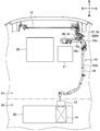
- FIG. 1 It is a top view which shows the state by which the refrigeration cycle apparatus in 1st Embodiment was arrange
- FIG. 12 is a cross-sectional view taken along line XII-XII in FIG. 11.
- FIG. 13 is a cross-sectional view taken along line XIII-XIII in FIG. 11.
- FIG. 12 is a cross-sectional view taken along line XIV-XIV in FIG. 11. It is a perspective view of the 1st connector for 2nd refrigerant
- a pair of connectors of the present disclosure is connected to a pair of connectors that connect an inlet pipe and an outlet pipe extending from the condenser and a refrigerant pipe separate from the inlet pipe. Has been applied.
- the refrigeration cycle apparatus 10 includes a compressor 11, a condenser 12, an expansion valve 13, an evaporator 14, and a refrigerant pipe 15 that connects these components.
- the compressor 11 compresses the sucked low-pressure refrigerant and discharges the high-pressure refrigerant.
- the condenser 12 is a heat exchanger for radiating heat, that is, a heat radiator that radiates and condenses the high-pressure refrigerant discharged from the compressor 11 by heat exchange with the outside air.
- the expansion valve 13 is a decompression device that decompresses and expands the refrigerant flowing out of the condenser 12.
- the evaporator 14 is an endothermic heat exchanger that absorbs and evaporates the refrigerant flowing out of the expansion valve 13 by heat exchange with the indoor blowing air.
- the compressor 11 and the condenser 12 are disposed in an engine room 21 of a vehicle in which an engine 20 for vehicle travel is accommodated.
- the compressor 11 is disposed next to the engine 20.
- the condenser 12 is disposed on the front side of the vehicle in the engine room 21.
- the expansion valve 13 and the evaporator 14 are included in an indoor air conditioning unit 23 disposed in the passenger compartment 22.
- the refrigerant pipe 15 is a refrigerant pipe 15 a that connects the refrigerant inlet side of the condenser 12 and the refrigerant discharge port side of the compressor 11, and a refrigerant that connects the refrigerant outlet side of the condenser 12 and the refrigerant inlet side of the expansion valve 13.
- the pipe 15b has a refrigerant pipe 15c that connects the refrigerant inlet side of the compressor 11 and the refrigerant outlet side of the evaporator 14.
- a part of the refrigerant pipe 15b and a part of the refrigerant pipe 15c are constituted by a single refrigerant pipe 15d having an inner pipe and an outer pipe, that is, an internal heat exchanger 15d.
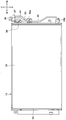
- the condenser 12 includes a heat exchange core portion 31 and a pair of header tanks 32 and 33.
- the heat exchange core 31 is formed by stacking a plurality of tubes (not shown) through which a refrigerant flows.
- the plurality of tubes extend in the vehicle left-right direction.
- the pair of header tanks 32 and 33 are disposed on both sides of the heat exchange core portion 31 in the left-right direction of the vehicle, and communicate with both end portions of the plurality of tubes.
- the condenser 12 includes an inlet pipe 34 and an outlet pipe 35 provided in the header tank 32.
- the inlet pipe 34 is a pipe connected to the refrigerant inlet of the condenser 12.
- the refrigerant flowing from the inlet pipe 34 flows inside the condenser 12.
- the outlet pipe 35 is a pipe connected to the refrigerant outlet of the condenser 12.
- the refrigerant that has flowed through the condenser 12 flows out from the outlet pipe 35.
- Both the inlet pipe 34 and the outlet pipe 35 extend upward from the header tank 32.
- An inlet pipe side connector 36 is provided at the end of the inlet pipe 34, and an outlet pipe side connector 37 is provided at the end of the outlet pipe 35.
- the inlet pipe side connector 36 and the outlet pipe side connector 37 are arranged adjacent to each other and adjacent to the upper end portion of the header tank 32.
- the inlet pipe side connector 36 and the outlet pipe side connector 37 are held by a holding member 38 attached to the condenser 12.
- the inlet pipe 34 and the inlet pipe side connector 36 are joined by brazing.
- the outlet pipe 35 and the outlet pipe side connector 37 are joined by brazing.
- the inlet pipe 34 and the outlet pipe 35 are fixed to the condenser 12 via connectors 39a and 39b, respectively.
- the inlet pipe 34, the inlet pipe side connector 36, the outlet pipe 35, and the outlet pipe side connector 37 are integrated with the condenser 12 in a state before being assembled to the vehicle body.
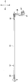
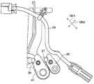
- the refrigerant pipe 15a connected to the inlet pipe 34 is provided with a refrigerant pipe-side connector 41 at the end thereof.
- the inlet pipe connector 36 and the refrigerant pipe connector 41 By assembling the inlet pipe connector 36 and the refrigerant pipe connector 41, the inlet pipe 34 and the refrigerant pipe 15a are connected. Therefore, the inlet pipe side connector 36 and the refrigerant pipe side connector 41 constitute a pair of connectors.
- the refrigerant pipe 15b connected to the outlet pipe 35 is provided with a refrigerant pipe side connector 42 at the end thereof.
- the outlet pipe side connector 37 and the refrigerant pipe side connector 42 constitute a pair of connectors.
- charge valves 43 and 44 are provided in the refrigerant pipes 15a and 15c, respectively.
- the charge valves 43 and 44 are refrigerant injection valves.
- the charge valves 43 and 44 are joined to the refrigerant inlets of the refrigerant pipes 15a and 15c, and are integrated with the refrigerant pipes 15a and 15c.
- the charge valves 43 and 44 have different shapes depending on the type of refrigerant.
- the refrigeration cycle apparatus 10 of the present embodiment uses R1234yf as the first refrigerant as the refrigerant. For this reason, the refrigerant pipes 15a and 15c have charge valves 43 and 44 for the first refrigerant, respectively.
- the refrigerant pipe 15 of the present embodiment is a refrigerant pipe dedicated to the first refrigerant.
- the inlet pipe side connector 36 and the refrigerant pipe side connector 41 are a pair of connectors for the first refrigerant.
- the outlet pipe side connector 37 and the refrigerant pipe side connector 42 are also a pair of connectors for the first refrigerant.
- the inlet pipe side connector 36 is referred to as a first connector
- the refrigerant pipe side connector 41 is referred to as a second connector
- the outlet pipe side connector 37 and the refrigerant pipe side connector 42 have the same structure as the inlet pipe side connector 36 and the refrigerant pipe side connector 41, respectively, and thus the description thereof will be omitted.
- the outlet pipe side connector 37 corresponds to the first connector
- the refrigerant pipe side connector 42 corresponds to the second connector.
- the first and second connectors 36 and 41 are so-called block joints.
- the first and second connectors 36 and 41 are both metal block bodies and are manufactured by a die casting method using a metal material such as an aluminum-based material.
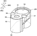
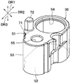
- the first connector 36 has one surface 51, the other surface 52 on the opposite side, and a side surface 53 that is continuous with both the one surface 51 and the other surface 52. Yes. Both the one surface 51 and the other surface 52 are flat surfaces.
- one surface 51 on the second connector 41 side constitutes an assembled surface.
- the assembly surface is a surface that faces and contacts the mating connector when the first and second connectors 36 and 41 are assembled.
- the assembly surface 51 of the first connector 36 is referred to as a first assembly surface 51.
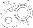
- the first assembly surface 51 is provided with a first flow path through hole 54 and a first fastening through hole 55.
- the first flow path through hole 54 is a through hole to which the inlet pipe 34 is connected.
- the first fastening through hole 55 is a through hole into which a screw 66 as a fastening member is inserted (see FIG. 12), and has a screw groove on the inner wall. Both the first flow path through hole 54 and the first fastening through hole 55 penetrate the first assembly surface 51 and the other surface 52. Both the axis of the first flow path through hole 54 and the axis of the first fastening through hole 55 are orthogonal to the first assembly surface 51.
- the first assembly surface 51 is formed with two concave portions 56 and 57 that are generated by being pushed by a die-cutting rod during manufacturing.
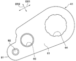
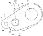
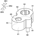
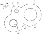
- the second connector 41 has one surface 61, the other surface 62 on the opposite side, and a side surface 63 that continues to both the one surface 61 and the other surface 62. Both the one surface 61 and the other surface 62 are flat surfaces.
- the assembly surface 61 of the second connector 41 is referred to as a second assembly surface 61.
- the second assembly surface 61 is provided with a second passage through hole 64 and a second fastening through hole 65.
- the second passage through-hole 64 is a through-hole in which the refrigerant pipe 15a is continuous.
- the second fastening through hole 65 is a through hole into which the screw 66 is inserted (see FIG. 12), and has a thread groove on the inner wall. Both the second passage through hole 64 and the second fastening through hole 65 penetrate the second assembly surface 61 and the other surface 62.
- the second flow path through hole 64 is provided at a position facing the first flow path through hole 54, and the second fastening through hole 65 is The first fastening through hole 55 is provided at a position facing the first fastening through hole 55.
- First and second assembly surfaces 51 and 61 are brought into contact with each other, and the first and second connectors 36 and 41 are assembled as shown in FIGS.
- the first and second flow passage through holes 54 and 64 communicate with each other
- the first and second fastening through holes 55 and 65 communicate with each other.
- Screws 66 are inserted into the first and second fastening through holes 55 and 65 in the communicated state.
- the first and second connectors 36 and 41 are fastened, and the inlet pipe 34 and the refrigerant pipe 15a are connected.
- the inlet pipe 34 is provided in the first flow path through hole 54 so that the position of the end of the inlet pipe 34 is the same as the position of the first assembly surface 51. Has been inserted. As a result, the first flow path through hole 54 and the inlet pipe 34 are connected.
- the refrigerant pipe 15 a is inserted into the second flow path through hole 64 so that the refrigerant pipe 15 a protrudes from the second assembly surface 61. Thereby, the through-hole 64 for 2nd flow paths and the refrigerant
- the end of the refrigerant pipe 15a is inserted inside the inlet pipe 34, and the inlet pipe 34 and the refrigerant pipe 15a are connected.
- the first and second connectors 36 and 41 are assembled to pass through the first flow path through hole 54 and the second flow path through hole 64 and from the refrigerant pipe 15 a to the inlet pipe 34.
- the refrigerant can flow to the The same applies to the outlet pipe side connector 37 and the refrigerant pipe side connector 42. That is, by assembling the first and second connectors 37 and 42, the refrigerant passes through the first flow path through hole 54 and the second flow path through hole 64 to the refrigerant pipe 15 b from the outlet pipe 35. Can flow.
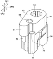
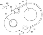
- first connector 36 of the present embodiment includes a first protruding portion 71 and a first protruding portion 72 as shown in FIGS.
- second connector 41 of this embodiment has the 2nd protrusion part 81 and the 2nd protrusion part 82, as shown in FIG.
- the first protruding portion 71 includes the first and second connectors 36 and 41 in the assembled state of the first connector 36, and the first and second fastening through holes 55 and 65. This is the portion that protrudes from the second assembly surface 61 of the second connector 41 when viewed from the direction DR3. In other words, the first protruding portion 71 has the first and second fastening penetrations more than the second assembly surface 61 of the second connector 41 of the first connector 36 in the assembled state of the first and second connectors 36 and 41. This is a portion located outside in the direction perpendicular to the axial direction DR3 of the holes 55 and 65.
- the first protrusion 71 is provided at the end of the first connector 36 on the first fastening through hole 55 side in the first direction DR1.
- the first direction DR1 in FIG. 7 is an arrangement direction of the first flow passage through holes 54 and the first fastening through holes 55
- the second direction DR2 in FIG. 7 is perpendicular to the first direction DR1.
- the first direction DR ⁇ b> 1 includes the center CL ⁇ b> 1 of the first and second fastening through holes 55 and 65, and the first and second passage through holes 54 and 64. This is a direction connecting the center CL2 in a straight line.
- the first protruding portion 71 protrudes from the portion having the first assembly surface 51 of the first connector 36 to the side away from the first fastening through hole 55 in the direction along the first direction DR1. For this reason, the first connector 36 has a shape extending long in the first direction DR1.
- the first protruding portion 72 is a portion protruding from the first protruding portion 71 toward the second connector 41 with respect to the position P ⁇ b> 1 of the first assembly surface 51. Therefore, the tip 72a of the first protrusion 72 is located closer to the second connector 41 than the position P1 of the first assembly surface 51 in the axial direction DR3 of the first and second fastening through holes 55 and 65. .
- the first protrusion 72 is formed integrally with the first protrusion 71.
- the first projecting portion 72 is formed by providing a step between the first assembly surface 51 and the first protruding portion 71.
- the second protruding portion 81 includes the first and second connectors 36 and 41 in the assembled state of the second connector 41, and the axes of the first and second fastening through holes 55 and 65. This is a portion protruding from the first assembly surface 51 of the first connector 36 when viewed from the direction DR3.
- the second protruding portion 81 in the assembled state of the first and second connectors 36 and 41, has a first and second fastening penetration than the first assembly surface 51 of the first connector 36 of the second connector 41. This is a portion located outside in the direction perpendicular to the axial direction DR3 of the holes 55 and 65.
- the second protruding portion 81 is an end of the second connector 41 on the second fastening through hole 65 side in the first direction DR1, as shown in FIG. Is provided.
- a first direction DR1 in FIG. 9 is an arrangement direction of the second flow passage through holes 64 and the second fastening through holes 65, similarly to the first direction DR1 in FIG.
- the second protruding portion 81 protrudes from the portion of the second connector 41 having the second assembly surface 61 to the side away from the second fastening through hole 65 in the direction along the first direction DR1. For this reason, the second connector 41 has a shape extending long in the first direction DR1.
- the first protruding portion 71 and the second protruding portion 81 are shifted from each other in the second direction DR2 so as not to interfere with each other when the first and second connectors 36 and 41 are assembled. Is arranged. That is, the 1st protrusion part 71 and the 2nd protrusion part 81 are each arrange
- the 2nd protrusion part 82 is a part which protrudes from the 2nd protrusion part 81 to the 1st connector 36 side rather than the position P2 of the 2nd assembly surface 61, as shown in FIG. Therefore, the tip 82a of the second protrusion 82 is located closer to the first connector 36 than the position P2 of the second assembly surface in the axial direction DR3 of the first and second fastening through holes 55 and 65.
- the surface of the second protrusion 81 on the first connector 36 side is a flat surface that is flush with the second assembly surface 61.
- the second protrusion 82 includes a press-fit pin 84 that is press-fitted into a hole 83 provided on the surface of the second protrusion 82 on the first connector 36 side.
- the outer peripheral edge of the first assembly surface 51 is such that the second protrusion 82 is positioned outside the first connector 36 in the assembled state of the first and second connectors 36 and 41.
- the position of the part 51a corresponding to the second protrusion 82 is set. That is, the distance L1 from the center CL1 of the first fastening through hole 55 to the outer peripheral edge of the first assembly surface 51 in the portion 51a corresponding to the second protrusion 82 in the outer peripheral edge of the first assembly surface 51. However, it is set shorter than the distance L2 from the center CL1 of the second fastening through hole 65 to the second protrusion 82.
- the outer peripheral edge of the second assembly surface 61 is such that the first projection 72 is positioned outside the second connector 41 when the first and second connectors 36 and 41 are assembled.
- the position of the part 61a corresponding to 72 is set. That is, the distance L3 from the center CL1 of the second fastening through hole 65 to the outer peripheral edge portion of the second assembly surface 61 in the portion 61a corresponding to the first protrusion 72 in the outer peripheral edge portion of the second assembly surface 61. Is set shorter than the distance L4 from the center of the first fastening through hole 55 to the first protrusion 72.
- the pair of connectors J36 and J41 for the second refrigerant is used in the refrigeration cycle apparatus 10 that uses R134a as the second refrigerant as the refrigerant.
- the pair of connectors J36, J41 for the second refrigerant has the basic structure of the pair of connectors 36, 41 for the first refrigerant.
- the pair of connectors 36 and 41 for the first refrigerant of the present embodiment is a design change with respect to the pair of connectors J36 and J41 for the second refrigerant.
- the first and second connectors J36 and J41 for the second refrigerant are protruded from the first and second connectors 36 and 41 for the first refrigerant, respectively.
- the structure is the same except that the parts 71 and 81 are not provided.
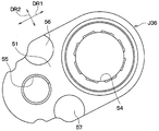
- the first connector J36 for the second refrigerant is similar to the first connector 36 for the first refrigerant, on the first assembly surface 51, A first fastening through hole 55 is provided.
- the first connector J36 for the second refrigerant does not have the first protruding portion 71, the outer peripheral edge of the first assembly surface 51 at the end portion on the first fastening through hole 55 side in the first direction DR1.
- the part has an arc shape.
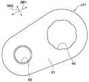
- the second connector J41 for the second refrigerant is similar to the second connector 41 for the first refrigerant.
- a second fastening through hole 65 is provided.
- the second connector J41 for the second refrigerant does not have the second protruding portion 81, the outer peripheral edge of the second assembly surface 61 at the end portion on the second fastening through hole 65 side in the first direction DR1.
- the part has an arc shape.
- the first and second connectors J36 and J41 for the second refrigerant are assembled in a state where the first and second assembly surfaces 51 and 61 are in contact with each other. Since the first and second connectors J36 and J41 for the second refrigerant do not have a protruding portion, they can be assembled.
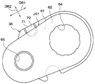
- the first protrusion 72 of the first connector 36 for the first refrigerant is assembled with the first connector 36 for the first refrigerant and the second connector J41 for the second refrigerant, as shown in FIGS.
- the 1st protrusion part 72 is provided in the position which hits the 2nd assembly surface 61 of 2nd connector J41 for 2nd refrigerant
- the second connector 41 for the first refrigerant has a portion 61a corresponding to the first protrusion 72 in the outer peripheral edge of the second assembly surface 61, as can be seen by comparing FIG. 11 and FIG. It is set at a position closer to the center CL1 of the second fastening through hole 65 than the outer peripheral edge portion of the second assembly surface 61 for the second refrigerant.
- the second protrusion 82 of the second connector 41 for the first refrigerant assembles the second connector 41 for the first refrigerant and the first connector J36 for the second refrigerant.
- the second projecting portion 82 is provided at a position where it contacts the first mounting surface 51 of the first connector J36 for the second refrigerant.
- the first connector 36 for the first refrigerant has a portion 51 a corresponding to the second protrusion 82 in the outer peripheral edge of the first mounting surface 51. It is set at a position closer to the center CL1 of the first fastening through hole 55 than the outer peripheral edge portion of the first attachment surface 51 for the second refrigerant.
- the components 11, 12, 13, and 14 of the refrigeration cycle apparatus 10 are mounted on the vehicle body, and the components 11, 12, 13, and 14 are cooled together. Connect with piping 15. At this time, an operator selects what has a connector according to the kind of refrigerant
- the operator in order to assemble the refrigeration cycle apparatus 10 using the first refrigerant, the operator can connect the refrigerant pipe 15 provided with the second connectors 41 and 42 for the first refrigerant, and the first connector for the first refrigerant.
- the inlet pipe 34 and the outlet pipe 35 of the condenser 12 provided with 36 and 37 are assembled.
- the first protrusion 72 is provided in the first protrusion 71 of the first connector 36 for the first refrigerant
- the second protrusion 82 is provided in the second protrusion 81 of the second connector 41 for the first refrigerant. Is provided.
- the position of the first protrusion 72 is set to a position that does not contact the second assembly surface 61 for the first refrigerant
- the position of the second protrusion 82 is the first assembly for the first refrigerant. The position is set so as not to contact the surface 51.
- the first projecting portion 72 does not interfere with the second assembly surface 61, and the second projecting portion 82 is the first assembly surface 51. Therefore, the first and second connectors 36 and 41 for the first refrigerant are assembled.
- the position of the 1st protrusion part 72 is set to the position which contacts the 2nd assembly surface 61 of the 2nd connector J41 for 2nd refrigerant
- the position of the 2nd protrusion part 82 is set to the position which contacts the 1st assembly surface 51 of the 1st connector J36 for 2nd refrigerant
- the first and second connectors 36 and 41 for the first refrigerant can be assembled together, and one of the first and second connectors 36 and 41 for the first refrigerant It is impossible to assemble one of the first and second connectors J36 and J41 for the second refrigerant. Accordingly, it is possible to prevent erroneous assembly of one of the first and second connectors 36 and 41 for the first refrigerant and one of the first and second connectors J36 and J41 for the second refrigerant. The same applies to the first and second connectors 37 and 41 for the first refrigerant.
- the refrigerant pipe 15 for the second refrigerant can be prevented from being erroneously assembled to the inlet pipe 34 and the outlet pipe 35 of the condenser 12 having the first connectors 36 and 37 for the first refrigerant.
- the shapes of the first and second connectors 36 and 41 for the first refrigerant are different from the shapes of the first and second connectors J36 and J41 for the second refrigerant, respectively. Change the design. Therefore, according to this embodiment, the design change of the shape of the 1st, 2nd connectors J36 and J41 for 2nd refrigerant
- coolants can be made unnecessary.
- the shape of the pair of connectors for the first refrigerant is changed from the pair of connectors J36 and J41 for the second refrigerant as in the connector described in Patent Document 1 above. It is possible to do. That is, although not shown, the first protrusion 51 is provided on the first assembly surface 51, and the second protrusion is provided on the second assembly surface 61. Further, a receiving hole for the second protrusion is provided on the first assembly surface 51, and a receiving hole for the first protrusion is provided on the second assembly surface 61.
- the other shapes of the pair of connectors for the first refrigerant are the same as the pair of connectors J36 and J41 for the second refrigerant.
- the first and second protrusions are not visually recognized in the assembled state of the pair of connectors for the first refrigerant.
- the pair of connectors for the first refrigerant and the pair of connectors J36 and J41 for the second refrigerant have the same outer shape. For this reason, the pair of connectors for the first refrigerant and the pair of connectors for the second refrigerant cannot be visually determined.
- the first protrusion 71 and the first protrusion 72 are It is located outside the side surface 63 of the second connector 41. Further, the second protruding portion 81 and the second protruding portion 82 are located outside the side surface 53 of the first connector 36. For this reason, even after the first and second connectors 36 and 41 are assembled, the first and second protruding portions 71 and 81 and the first and second protruding portions 72 and 82 can be visually observed.
- the first and second protruding portions 71 and 81 and the presence and absence of the first and second projecting portions 72 and 82 are visually checked by an operator. It is possible to determine whether or not both the first and second connectors 36 and 41 are used.
- the protruding portions 72 and 82 are provided on the protruding portions 71 and 81 of the one connector 36 and 41, like the connector described in Patent Document 1, it is received by the mating connector. There is no need to provide a hole. Thereby, the enlargement of the connector by forming a receiving hole can be avoided.
- FIG. 25 is an enlarged view of a region XXV in FIG.
- the first protrusion 71 is provided at the end of the first connectors 36 and 37 on the first fastening through hole 55 side in the first direction DR1.
- the 2nd protrusion part 81 is provided in the edge part by the side of the 2nd fastening through-hole 65 in 1st direction DR1 among the 2nd connectors 41 and 42. As shown in FIG. Thus, as shown in FIG. 25, even if the wire harness 24 is located next to the first and second connectors 36, 37, 41, and 42 in the second direction DR2, the first and second protrusions are caused. Portions 71 and 81 and first and second protrusions 72 and 82 can be provided.
- first and second connectors 36, 37, 41, and 42 of the present embodiment it is possible to cope with an engine room environment in which the layout conditions are severe.
- the first protruding portion 71 is located between the first flow path through hole 54 and the first fastening through hole 55 in the first connector 36 and in the second direction DR2. It is provided at one end.
- the second protruding portion 81 is between the second flow passage through hole 64 and the second fastening through hole 65 in the second connector 41, and In the assembled state of the first and second connectors 36 and 41, the second connector 36 is provided at the end opposite to the first protruding portion 71 side in the second direction DR2.
- the first projecting portion 72 includes a first connector 36 for the first refrigerant and a second connector J41 for the second refrigerant.
- the first protrusion 72 is provided at a position where it contacts the second attachment surface 61 for the second refrigerant.
- the second protrusion 82 when the second protrusion 82 is to be assembled with the second connector 41 for the first refrigerant and the first connector J36 for the second refrigerant, the second protrusion 82 is It is provided at a position where it hits the first attachment surface 51 for two refrigerants.
- the present embodiment in the engine room 21, even if there are parts mounted in the engine room 21 next to the first and second connectors 36 and 41 in the first direction DR 1, The 1st, 2nd protrusion parts 71 and 81 and the 1st, 2nd protrusion parts 72 and 82 can be provided.
- the first and second connectors 36 and 41 of the present embodiment it is possible to cope with an engine room environment in which layout conditions are severe.
- the first connectors 36 and 37 for the first refrigerant are provided in the inlet pipe 34 and the outlet pipe 35 of the condenser 12, respectively, but this is not a limitation.
- the first connectors 36 and 37 for the first refrigerant may be directly provided in the header tanks 32 and 33 without using the inlet pipe 34 and the outlet pipe 35.
- the header tank provided with the first connector corresponds to a first flow path forming member that forms a fluid flow path.
- the refrigerant pipe 15b and the refrigerant pipe 15c are integrated, but may not be integrated.
- the first and second connectors for the first refrigerant may be provided for each of the refrigerant pipes that need to be changed according to the type of refrigerant and the flow path forming components connected thereto.
- the pair of connectors according to the present disclosure is applied to the pair of connectors 36 and 41 for connecting the condenser 12 and the refrigerant pipe 15, but the present invention is not limited to this case.
- the pair of connectors of the present disclosure may be applied to a pair of connectors for connecting the compressor 11 and the refrigerant pipe 15.
- the pair of connectors of the present disclosure is applied to the pair of connectors for the first refrigerant, but the present invention is not limited to this case.
- the pair of connectors of the present disclosure may be applied not to the pair of connectors for the first refrigerant but to the pair of connectors for the second refrigerant.
- the pair of connectors of the present disclosure is applied to the pair of refrigerant piping connectors applied to the vehicle refrigeration cycle apparatus 10, but the present invention is not limited to this case.
- a pair of connectors for connecting a first flow path forming member that forms a fluid flow path and a second flow path forming member that is separate from the first flow path forming member and that forms a fluid flow path On the other hand, a pair of connectors of this indication may be applied.
Landscapes
- Engineering & Computer Science (AREA)
- General Engineering & Computer Science (AREA)
- Mechanical Engineering (AREA)
- Physics & Mathematics (AREA)
- Thermal Sciences (AREA)
- Air-Conditioning For Vehicles (AREA)
- Joints With Pressure Members (AREA)
- Flanged Joints, Insulating Joints, And Other Joints (AREA)
Abstract
Description
一対のコネクタは、
流体の流路を形成する第1流路形成部材に設けられる第1コネクタと、
流体の流路を形成する第2流路形成部材に設けられ、第1コネクタに組み付けられる第2コネクタとを備え、
第1コネクタは、第2コネクタとの組み付け状態において、第2コネクタと接触する第1組み付け面を有し、
第1組み付け面には、第1流路用貫通孔と第1締結用貫通孔とが設けられており、
第2コネクタは、第1コネクタとの組み付け状態において、第1組み付け面と接触する第2組み付け面を有し、
第2組み付け面には、第1コネクタとの組み付け状態において、第2流路用貫通孔が第1流路用貫通孔と対向する位置に設けられるとともに、第2締結用貫通孔が第1締結用貫通孔と対向する位置に設けられており、
第1コネクタと第2コネクタの組み付け状態において、第1締結用貫通孔と第2締結用貫通孔に締結部材が挿入されるとともに、第1流路用貫通孔内と第2流路用貫通孔内とを通って、第1流路形成部材と第2流路形成部材の一方から他方へ流体が流れるようになっており、
さらに、第1コネクタは、第2コネクタとの組み付け状態において、第2組み付け面よりも外側にはみ出ている第1はみ出し部と、第1はみ出し部から第1組み付け面の位置よりも第2コネクタ側に突き出ている第1突出部とを有し、
第2コネクタは、第1コネクタとの組み付け状態において、第1組み付け面よりも外側にはみ出ている第2はみ出し部と、第2はみ出し部から第2組み付け面の位置よりも第1コネクタ側に突き出ている第2突出部とを有する。
本実施形態では、車両用空調装置を構成する冷凍サイクル装置において、凝縮器から延びる入口配管および出口配管と、それとは別体の冷媒配管とを接続する一対のコネクタに、本開示の一対のコネクタを適用している。
本実施形態は、図26~31に示すように、第1実施形態に対して、第1冷媒用の第1、第2コネクタ36、41の第1、第2はみ出し部71、81の位置を変更したものである。冷凍サイクル装置10のその他の構成は、第1実施形態と同じである。
本開示は上記した実施形態に限定されるものではなく、下記のように、請求の範囲に記載した範囲内において適宜変更が可能である。
Claims (5)
- 一対のコネクタであって、
流体の流路を形成する第1流路形成部材(34、35)に設けられる第1コネクタ(36、37)と、
流体の流路を形成する第2流路形成部材(15a、15b)に設けられ、前記第1コネクタに組み付けられる第2コネクタ(41、42)とを備え、
前記第1コネクタは、前記第2コネクタとの組み付け状態において、前記第2コネクタと接触する第1組み付け面(51)を有し、
前記第1組み付け面には、第1流路用貫通孔(54)と第1締結用貫通孔(55)とが設けられており、
前記第2コネクタは、前記第1コネクタとの組み付け状態において、前記第1組み付け面と接触する第2組み付け面(61)を有し、
前記第2組み付け面には、前記第1コネクタとの組み付け状態において、第2流路用貫通孔(64)が前記第1流路用貫通孔と対向する位置に設けられるとともに、第2締結用貫通孔(65)が前記第1締結用貫通孔と対向する位置に設けられており、
前記第1コネクタと前記第2コネクタの組み付け状態において、前記第1締結用貫通孔と前記第2締結用貫通孔に締結部材(66)が挿入されるとともに、前記第1流路用貫通孔内と前記第2流路用貫通孔内とを通って、前記第1流路形成部材と前記第2流路形成部材の一方から他方へ前記流体が流れるようになっており、
さらに、前記第1コネクタは、前記第2コネクタとの組み付け状態において、前記第2組み付け面よりも外側にはみ出ている第1はみ出し部(71)と、前記第1はみ出し部から第1組み付け面の位置(P1)よりも前記第2コネクタ側に突き出ている第1突出部(72)とを有し、
前記第2コネクタは、前記第1コネクタとの組み付け状態において、前記第1組み付け面よりも外側にはみ出ている第2はみ出し部(81)と、前記第2はみ出し部から前記第2組み付け面の位置(P2)よりも前記第1コネクタ側に突き出ている第2突出部(82)とを有する一対のコネクタ。 - 前記第1はみ出し部は、前記第1コネクタのうち前記第1流路用貫通孔と前記第1締結用貫通孔の並び方向(DR1)における前記第1締結用貫通孔側の端部に設けられ、
前記第2はみ出し部は、前記第2コネクタのうち前記第2流路用貫通孔と前記第2締結用貫通孔の並び方向(DR1)における前記第2締結用貫通孔側の端部に設けられている請求項1に記載の一対のコネクタ。 - 前記一対のコネクタは、車両用冷凍サイクル装置(10)に適用され、
前記流体は、冷媒である請求項1または2に記載の一対のコネクタ。 - 請求項1または2に記載の一対のコネクタと、
前記第1流路形成部材(34、35)と、
前記第2流路形成部材(15a、15b)とを備える冷凍サイクル装置。 - 冷媒が流入する入口配管(34)を有し、冷媒を放熱させる放熱器(12)と、
冷媒注入用のバルブ(43)を有し、前記入口配管に接続される冷媒配管(15a)とを備え、
前記第1コネクタは、前記第1流路形成部材としての前記入口配管に設けられ、
前記第2コネクタは、前記第2流路形成部材としての前記冷媒配管に設けられる請求項4に記載の冷凍サイクル装置。
Priority Applications (5)
| Application Number | Priority Date | Filing Date | Title |
|---|---|---|---|
| DE112016002972.1T DE112016002972T5 (de) | 2015-07-01 | 2016-05-23 | Paar von Verbindungselementen |
| JP2017526218A JP6418328B2 (ja) | 2015-07-01 | 2016-05-23 | 一対のコネクタ |
| KR1020177019845A KR101906584B1 (ko) | 2015-07-01 | 2016-05-23 | 한쌍의 커넥터 |
| US15/578,274 US10544890B2 (en) | 2015-07-01 | 2016-05-23 | Pair of connectors |
| CN201680013928.0A CN107407448B (zh) | 2015-07-01 | 2016-05-23 | 一对连接器以及具备其的制冷循环装置 |
Applications Claiming Priority (2)
| Application Number | Priority Date | Filing Date | Title |
|---|---|---|---|
| JP2015132891 | 2015-07-01 | ||
| JP2015-132891 | 2015-07-01 |
Publications (1)
| Publication Number | Publication Date |
|---|---|
| WO2017002482A1 true WO2017002482A1 (ja) | 2017-01-05 |
Family
ID=57608464
Family Applications (1)
| Application Number | Title | Priority Date | Filing Date |
|---|---|---|---|
| PCT/JP2016/065151 Ceased WO2017002482A1 (ja) | 2015-07-01 | 2016-05-23 | 一対のコネクタ |
Country Status (6)
| Country | Link |
|---|---|
| US (1) | US10544890B2 (ja) |
| JP (1) | JP6418328B2 (ja) |
| KR (1) | KR101906584B1 (ja) |
| CN (1) | CN107407448B (ja) |
| DE (1) | DE112016002972T5 (ja) |
| WO (1) | WO2017002482A1 (ja) |
Families Citing this family (1)
| Publication number | Priority date | Publication date | Assignee | Title |
|---|---|---|---|---|
| US11754204B2 (en) * | 2020-07-27 | 2023-09-12 | Hanon Systems | Stabilized h-plate |
Citations (6)
| Publication number | Priority date | Publication date | Assignee | Title |
|---|---|---|---|---|
| JPH01114416U (ja) * | 1988-01-29 | 1989-08-01 | ||
| JPH058172U (ja) * | 1991-07-19 | 1993-02-05 | 三菱重工業株式会社 | 配管継手 |
| JP2002526736A (ja) * | 1998-10-02 | 2002-08-20 | エアロクイップ コーポレーション | 管継手アセンブリ |
| JP3143147U (ja) * | 2008-04-28 | 2008-07-10 | ジョプラックス株式会社 | 浄水器用継手の連結構造 |
| KR20130019149A (ko) * | 2011-08-16 | 2013-02-26 | 한라공조주식회사 | 차량용 공조장치 |
| JP2013227987A (ja) * | 2012-04-24 | 2013-11-07 | Tigers Polymer Corp | コネクタ部材接続構造 |
Family Cites Families (9)
| Publication number | Priority date | Publication date | Assignee | Title |
|---|---|---|---|---|
| US4069686A (en) * | 1976-09-07 | 1978-01-24 | Hoelman Walter A | Coupling for use in servicing air conditioning systems |
| US6140616A (en) * | 1998-09-25 | 2000-10-31 | Aehr Test Systems | Wafer level burn-in and test thermal chuck and method |
| US6834893B2 (en) | 2001-11-01 | 2004-12-28 | Visteon Global Technologies, Inc. | Peanut fittings for CO2 air conditioning systems |
| KR100488218B1 (ko) * | 2002-01-09 | 2005-05-10 | 주식회사 프라코이엔지 | 관 이음 플랜지 |
| JP4096832B2 (ja) * | 2003-07-22 | 2008-06-04 | 株式会社デンソー | 冷凍サイクル用配管継手 |
| JP2008089035A (ja) | 2006-09-29 | 2008-04-17 | Denso Corp | 配管継手 |
| JP2008215585A (ja) | 2007-03-07 | 2008-09-18 | Denso Corp | 配管継手 |
| US8141911B2 (en) * | 2009-03-19 | 2012-03-27 | Halla Climate Control Corporation | Pipe connection joint |
| CN102996933A (zh) * | 2012-11-27 | 2013-03-27 | 芜湖博耐尔汽车电气系统有限公司 | 汽车空调管路对接结构 |
-
2016
- 2016-05-23 DE DE112016002972.1T patent/DE112016002972T5/de active Pending
- 2016-05-23 US US15/578,274 patent/US10544890B2/en active Active
- 2016-05-23 KR KR1020177019845A patent/KR101906584B1/ko active Active
- 2016-05-23 CN CN201680013928.0A patent/CN107407448B/zh active Active
- 2016-05-23 WO PCT/JP2016/065151 patent/WO2017002482A1/ja not_active Ceased
- 2016-05-23 JP JP2017526218A patent/JP6418328B2/ja active Active
Patent Citations (6)
| Publication number | Priority date | Publication date | Assignee | Title |
|---|---|---|---|---|
| JPH01114416U (ja) * | 1988-01-29 | 1989-08-01 | ||
| JPH058172U (ja) * | 1991-07-19 | 1993-02-05 | 三菱重工業株式会社 | 配管継手 |
| JP2002526736A (ja) * | 1998-10-02 | 2002-08-20 | エアロクイップ コーポレーション | 管継手アセンブリ |
| JP3143147U (ja) * | 2008-04-28 | 2008-07-10 | ジョプラックス株式会社 | 浄水器用継手の連結構造 |
| KR20130019149A (ko) * | 2011-08-16 | 2013-02-26 | 한라공조주식회사 | 차량용 공조장치 |
| JP2013227987A (ja) * | 2012-04-24 | 2013-11-07 | Tigers Polymer Corp | コネクタ部材接続構造 |
Also Published As
| Publication number | Publication date |
|---|---|
| JPWO2017002482A1 (ja) | 2017-11-24 |
| KR101906584B1 (ko) | 2018-10-11 |
| CN107407448A (zh) | 2017-11-28 |
| US20180142816A1 (en) | 2018-05-24 |
| DE112016002972T5 (de) | 2018-03-15 |
| US10544890B2 (en) | 2020-01-28 |
| JP6418328B2 (ja) | 2018-11-07 |
| KR20170097140A (ko) | 2017-08-25 |
| CN107407448B (zh) | 2019-05-28 |
Similar Documents
| Publication | Publication Date | Title |
|---|---|---|
| CN108027225B (zh) | 热交换器、热交换器的制造方法 | |
| JP5351386B2 (ja) | 熱交換器の配管コネクタ | |
| KR101841373B1 (ko) | 증발기를 팽창 밸브에 결합하기 위한 장치 | |
| CN113167516B (zh) | 内部换热器及具有内部换热器的制冷循环装置 | |
| EP3086056B1 (en) | Accumulator, air conditioning device, and method for manufacturing accumulator | |
| US7219717B2 (en) | Evaporator and Refrigeration cycle | |
| KR101211637B1 (ko) | 다방향 커넥터를 구비하는 이중관 열교환기 및 이를 구비하는 차량용 냉방 장치 | |
| CN103206884A (zh) | 集管单元以及具有该集管单元的热交换器 | |
| CN110741220B (zh) | 热交换器 | |
| US20090146415A1 (en) | Pipe-joint structure for heat exchanger | |
| WO2007013439A1 (ja) | 熱交換器 | |
| JP6418328B2 (ja) | 一対のコネクタ | |
| JP2016200312A (ja) | 熱交換器、および熱交換器の製造方法 | |
| CN114485222A (zh) | 一种换热器、换热组件及一种热管理系统 | |
| JP2015227737A (ja) | 熱交換器用ヘッダ | |
| US10300767B2 (en) | Heat exchanger and radiator-condenser unit | |
| CN106679244A (zh) | 制冷剂管路以及具备该制冷剂管路的车辆用空调制冷循环 | |
| JP4690883B2 (ja) | 熱交換器および空気調和機 | |
| JP2010025460A (ja) | 二重管式熱交換器用継手 | |
| CN114207365A (zh) | 水冷式冷凝器 | |
| JP2007333283A (ja) | 蒸気圧縮式冷凍回路及び当該回路を用いた車両用空調システム | |
| JP7569757B2 (ja) | 熱交換器 | |
| JP4045955B2 (ja) | 液冷媒配管 | |
| JP2009047401A (ja) | 熱交換器用ヘッダタンク構造 | |
| JP6464926B2 (ja) | 冷媒配管接続継手 |
Legal Events
| Date | Code | Title | Description |
|---|---|---|---|
| 121 | Ep: the epo has been informed by wipo that ep was designated in this application |
Ref document number: 16817591 Country of ref document: EP Kind code of ref document: A1 |
|
| ENP | Entry into the national phase |
Ref document number: 2017526218 Country of ref document: JP Kind code of ref document: A Ref document number: 20177019845 Country of ref document: KR Kind code of ref document: A |
|
| WWE | Wipo information: entry into national phase |
Ref document number: 15578274 Country of ref document: US |
|
| WWE | Wipo information: entry into national phase |
Ref document number: 112016002972 Country of ref document: DE |
|
| 122 | Ep: pct application non-entry in european phase |
Ref document number: 16817591 Country of ref document: EP Kind code of ref document: A1 |