WO2016208580A1 - Structure d'insonorisation, et procédé de fabrication de celle-ci - Google Patents
Structure d'insonorisation, et procédé de fabrication de celle-ci Download PDFInfo
- Publication number
- WO2016208580A1 WO2016208580A1 PCT/JP2016/068392 JP2016068392W WO2016208580A1 WO 2016208580 A1 WO2016208580 A1 WO 2016208580A1 JP 2016068392 W JP2016068392 W JP 2016068392W WO 2016208580 A1 WO2016208580 A1 WO 2016208580A1
- Authority
- WO
- WIPO (PCT)
- Prior art keywords
- soundproof
- film
- frame
- cell
- frequency
- Prior art date
Links
- 238000004519 manufacturing process Methods 0.000 title abstract description 9
- 239000012528 membrane Substances 0.000 claims abstract description 108
- 230000005540 biological transmission Effects 0.000 claims abstract description 94
- 239000000463 material Substances 0.000 claims abstract description 59
- 238000010521 absorption reaction Methods 0.000 claims description 80
- 239000010410 layer Substances 0.000 claims description 44
- 238000006073 displacement reaction Methods 0.000 claims description 16
- 239000002356 single layer Substances 0.000 claims description 10
- 230000000149 penetrating effect Effects 0.000 claims 1
- 230000000873 masking effect Effects 0.000 abstract 2
- 230000001747 exhibiting effect Effects 0.000 abstract 1
- 239000010408 film Substances 0.000 description 458
- 238000009413 insulation Methods 0.000 description 88
- 229920002799 BoPET Polymers 0.000 description 41
- 230000000704 physical effect Effects 0.000 description 33
- 238000000034 method Methods 0.000 description 32
- 239000000853 adhesive Substances 0.000 description 29
- 230000001070 adhesive effect Effects 0.000 description 29
- 238000004088 simulation Methods 0.000 description 29
- 230000000052 comparative effect Effects 0.000 description 17
- 238000005259 measurement Methods 0.000 description 17
- 239000000428 dust Substances 0.000 description 12
- 238000012545 processing Methods 0.000 description 12
- -1 specifically Substances 0.000 description 12
- 230000000694 effects Effects 0.000 description 11
- RNFJDJUURJAICM-UHFFFAOYSA-N 2,2,4,4,6,6-hexaphenoxy-1,3,5-triaza-2$l^{5},4$l^{5},6$l^{5}-triphosphacyclohexa-1,3,5-triene Chemical compound N=1P(OC=2C=CC=CC=2)(OC=2C=CC=CC=2)=NP(OC=2C=CC=CC=2)(OC=2C=CC=CC=2)=NP=1(OC=1C=CC=CC=1)OC1=CC=CC=C1 RNFJDJUURJAICM-UHFFFAOYSA-N 0.000 description 10
- 229910052782 aluminium Inorganic materials 0.000 description 10
- XAGFODPZIPBFFR-UHFFFAOYSA-N aluminium Chemical compound [Al] XAGFODPZIPBFFR-UHFFFAOYSA-N 0.000 description 10
- 239000003063 flame retardant Substances 0.000 description 10
- 230000001965 increasing effect Effects 0.000 description 9
- 239000011358 absorbing material Substances 0.000 description 8
- 229920000139 polyethylene terephthalate Polymers 0.000 description 8
- 239000005020 polyethylene terephthalate Substances 0.000 description 8
- 239000006096 absorbing agent Substances 0.000 description 7
- 238000004458 analytical method Methods 0.000 description 7
- 230000008859 change Effects 0.000 description 7
- 230000007246 mechanism Effects 0.000 description 7
- NIXOWILDQLNWCW-UHFFFAOYSA-N acrylic acid group Chemical group C(C=C)(=O)O NIXOWILDQLNWCW-UHFFFAOYSA-N 0.000 description 6
- 238000010586 diagram Methods 0.000 description 6
- 238000002474 experimental method Methods 0.000 description 6
- 239000012774 insulation material Substances 0.000 description 6
- 229920003023 plastic Polymers 0.000 description 6
- 239000004033 plastic Substances 0.000 description 6
- 230000009471 action Effects 0.000 description 5
- 238000004364 calculation method Methods 0.000 description 5
- 238000013461 design Methods 0.000 description 5
- 235000019589 hardness Nutrition 0.000 description 5
- 238000003754 machining Methods 0.000 description 5
- 229910052751 metal Inorganic materials 0.000 description 5
- 239000002184 metal Substances 0.000 description 5
- 239000011347 resin Substances 0.000 description 5
- 229920005989 resin Polymers 0.000 description 5
- XEEYBQQBJWHFJM-UHFFFAOYSA-N Iron Chemical compound [Fe] XEEYBQQBJWHFJM-UHFFFAOYSA-N 0.000 description 4
- 238000005192 partition Methods 0.000 description 4
- 239000004417 polycarbonate Substances 0.000 description 4
- 229920001721 polyimide Polymers 0.000 description 4
- 239000004926 polymethyl methacrylate Substances 0.000 description 4
- 238000004080 punching Methods 0.000 description 4
- JOYRKODLDBILNP-UHFFFAOYSA-N Ethyl urethane Chemical compound CCOC(N)=O JOYRKODLDBILNP-UHFFFAOYSA-N 0.000 description 3
- 239000004642 Polyimide Substances 0.000 description 3
- 230000008901 benefit Effects 0.000 description 3
- 239000004566 building material Substances 0.000 description 3
- 239000003990 capacitor Substances 0.000 description 3
- 239000004918 carbon fiber reinforced polymer Substances 0.000 description 3
- 239000000919 ceramic Substances 0.000 description 3
- 230000008878 coupling Effects 0.000 description 3
- 238000010168 coupling process Methods 0.000 description 3
- 238000005859 coupling reaction Methods 0.000 description 3
- 238000005553 drilling Methods 0.000 description 3
- 239000011521 glass Substances 0.000 description 3
- 229910010272 inorganic material Inorganic materials 0.000 description 3
- 239000011147 inorganic material Substances 0.000 description 3
- 230000003993 interaction Effects 0.000 description 3
- 239000004745 nonwoven fabric Substances 0.000 description 3
- 229920003229 poly(methyl methacrylate) Polymers 0.000 description 3
- 229920000515 polycarbonate Polymers 0.000 description 3
- 238000003860 storage Methods 0.000 description 3
- 238000002834 transmittance Methods 0.000 description 3
- 238000009423 ventilation Methods 0.000 description 3
- 239000004925 Acrylic resin Substances 0.000 description 2
- 229920000178 Acrylic resin Polymers 0.000 description 2
- 229920002284 Cellulose triacetate Polymers 0.000 description 2
- VYZAMTAEIAYCRO-UHFFFAOYSA-N Chromium Chemical compound [Cr] VYZAMTAEIAYCRO-UHFFFAOYSA-N 0.000 description 2
- ZOKXTWBITQBERF-UHFFFAOYSA-N Molybdenum Chemical compound [Mo] ZOKXTWBITQBERF-UHFFFAOYSA-N 0.000 description 2
- PXHVJJICTQNCMI-UHFFFAOYSA-N Nickel Chemical compound [Ni] PXHVJJICTQNCMI-UHFFFAOYSA-N 0.000 description 2
- KDLHZDBZIXYQEI-UHFFFAOYSA-N Palladium Chemical compound [Pd] KDLHZDBZIXYQEI-UHFFFAOYSA-N 0.000 description 2
- 239000004696 Poly ether ether ketone Substances 0.000 description 2
- 229930182556 Polyacetal Natural products 0.000 description 2
- 239000004697 Polyetherimide Substances 0.000 description 2
- 239000004734 Polyphenylene sulfide Substances 0.000 description 2
- 229920000297 Rayon Polymers 0.000 description 2
- IDCBOTIENDVCBQ-UHFFFAOYSA-N TEPP Chemical compound CCOP(=O)(OCC)OP(=O)(OCC)OCC IDCBOTIENDVCBQ-UHFFFAOYSA-N 0.000 description 2
- RTAQQCXQSZGOHL-UHFFFAOYSA-N Titanium Chemical compound [Ti] RTAQQCXQSZGOHL-UHFFFAOYSA-N 0.000 description 2
- NNLVGZFZQQXQNW-ADJNRHBOSA-N [(2r,3r,4s,5r,6s)-4,5-diacetyloxy-3-[(2s,3r,4s,5r,6r)-3,4,5-triacetyloxy-6-(acetyloxymethyl)oxan-2-yl]oxy-6-[(2r,3r,4s,5r,6s)-4,5,6-triacetyloxy-2-(acetyloxymethyl)oxan-3-yl]oxyoxan-2-yl]methyl acetate Chemical compound O([C@@H]1O[C@@H]([C@H]([C@H](OC(C)=O)[C@H]1OC(C)=O)O[C@H]1[C@@H]([C@@H](OC(C)=O)[C@H](OC(C)=O)[C@@H](COC(C)=O)O1)OC(C)=O)COC(=O)C)[C@@H]1[C@@H](COC(C)=O)O[C@@H](OC(C)=O)[C@H](OC(C)=O)[C@H]1OC(C)=O NNLVGZFZQQXQNW-ADJNRHBOSA-N 0.000 description 2
- 238000004378 air conditioning Methods 0.000 description 2
- 229910052804 chromium Inorganic materials 0.000 description 2
- 239000011651 chromium Substances 0.000 description 2
- 238000010276 construction Methods 0.000 description 2
- 230000008602 contraction Effects 0.000 description 2
- 230000007423 decrease Effects 0.000 description 2
- 238000003795 desorption Methods 0.000 description 2
- 239000013013 elastic material Substances 0.000 description 2
- 239000011152 fibreglass Substances 0.000 description 2
- 230000006872 improvement Effects 0.000 description 2
- 239000011810 insulating material Substances 0.000 description 2
- 229910052742 iron Inorganic materials 0.000 description 2
- 239000007769 metal material Substances 0.000 description 2
- 229910052750 molybdenum Inorganic materials 0.000 description 2
- 239000011733 molybdenum Substances 0.000 description 2
- 230000002093 peripheral effect Effects 0.000 description 2
- 230000035699 permeability Effects 0.000 description 2
- 230000001699 photocatalysis Effects 0.000 description 2
- BASFCYQUMIYNBI-UHFFFAOYSA-N platinum Chemical compound [Pt] BASFCYQUMIYNBI-UHFFFAOYSA-N 0.000 description 2
- 229920002492 poly(sulfone) Polymers 0.000 description 2
- 229920001230 polyarylate Polymers 0.000 description 2
- 229920001707 polybutylene terephthalate Polymers 0.000 description 2
- 229920002530 polyetherether ketone Polymers 0.000 description 2
- 229920001601 polyetherimide Polymers 0.000 description 2
- 229920006324 polyoxymethylene Polymers 0.000 description 2
- 229920000069 polyphenylene sulfide Polymers 0.000 description 2
- 239000004800 polyvinyl chloride Substances 0.000 description 2
- 229920000915 polyvinyl chloride Polymers 0.000 description 2
- 238000003672 processing method Methods 0.000 description 2
- 239000007921 spray Substances 0.000 description 2
- 239000010409 thin film Substances 0.000 description 2
- 229910052719 titanium Inorganic materials 0.000 description 2
- 239000010936 titanium Substances 0.000 description 2
- 238000012546 transfer Methods 0.000 description 2
- QLZJUIZVJLSNDD-UHFFFAOYSA-N 2-(2-methylidenebutanoyloxy)ethyl 2-methylidenebutanoate Chemical compound CCC(=C)C(=O)OCCOC(=O)C(=C)CC QLZJUIZVJLSNDD-UHFFFAOYSA-N 0.000 description 1
- 229920006353 Acrylite® Polymers 0.000 description 1
- 229920003319 Araldite® Polymers 0.000 description 1
- 229920000049 Carbon (fiber) Polymers 0.000 description 1
- 239000004709 Chlorinated polyethylene Substances 0.000 description 1
- RYGMFSIKBFXOCR-UHFFFAOYSA-N Copper Chemical compound [Cu] RYGMFSIKBFXOCR-UHFFFAOYSA-N 0.000 description 1
- FYYHWMGAXLPEAU-UHFFFAOYSA-N Magnesium Chemical compound [Mg] FYYHWMGAXLPEAU-UHFFFAOYSA-N 0.000 description 1
- 239000004698 Polyethylene Substances 0.000 description 1
- 229920001328 Polyvinylidene chloride Polymers 0.000 description 1
- BQCADISMDOOEFD-UHFFFAOYSA-N Silver Chemical compound [Ag] BQCADISMDOOEFD-UHFFFAOYSA-N 0.000 description 1
- 229910000831 Steel Inorganic materials 0.000 description 1
- 239000004830 Super Glue Substances 0.000 description 1
- ATJFFYVFTNAWJD-UHFFFAOYSA-N Tin Chemical compound [Sn] ATJFFYVFTNAWJD-UHFFFAOYSA-N 0.000 description 1
- QCWXUUIWCKQGHC-UHFFFAOYSA-N Zirconium Chemical compound [Zr] QCWXUUIWCKQGHC-UHFFFAOYSA-N 0.000 description 1
- 238000000862 absorption spectrum Methods 0.000 description 1
- 239000012814 acoustic material Substances 0.000 description 1
- 229910045601 alloy Inorganic materials 0.000 description 1
- 239000000956 alloy Substances 0.000 description 1
- 238000000137 annealing Methods 0.000 description 1
- 239000004760 aramid Substances 0.000 description 1
- 229920003235 aromatic polyamide Polymers 0.000 description 1
- 230000000903 blocking effect Effects 0.000 description 1
- 239000004917 carbon fiber Substances 0.000 description 1
- 239000003575 carbonaceous material Substances 0.000 description 1
- 229920002678 cellulose Polymers 0.000 description 1
- 239000001913 cellulose Substances 0.000 description 1
- VNTLIPZTSJSULJ-UHFFFAOYSA-N chromium molybdenum Chemical compound [Cr].[Mo] VNTLIPZTSJSULJ-UHFFFAOYSA-N 0.000 description 1
- 239000011248 coating agent Substances 0.000 description 1
- 238000000576 coating method Methods 0.000 description 1
- 238000011109 contamination Methods 0.000 description 1
- 238000007796 conventional method Methods 0.000 description 1
- 229920001577 copolymer Polymers 0.000 description 1
- 229910052802 copper Inorganic materials 0.000 description 1
- 239000010949 copper Substances 0.000 description 1
- 230000001419 dependent effect Effects 0.000 description 1
- 238000005516 engineering process Methods 0.000 description 1
- 230000007613 environmental effect Effects 0.000 description 1
- 229920006332 epoxy adhesive Polymers 0.000 description 1
- 239000003822 epoxy resin Substances 0.000 description 1
- 229920006244 ethylene-ethyl acrylate Polymers 0.000 description 1
- 239000005042 ethylene-ethyl acrylate Substances 0.000 description 1
- 239000000835 fiber Substances 0.000 description 1
- 239000000945 filler Substances 0.000 description 1
- 150000002222 fluorine compounds Chemical class 0.000 description 1
- 239000011888 foil Substances 0.000 description 1
- 239000003365 glass fiber Substances 0.000 description 1
- PCHJSUWPFVWCPO-UHFFFAOYSA-N gold Chemical compound [Au] PCHJSUWPFVWCPO-UHFFFAOYSA-N 0.000 description 1
- 229910052737 gold Inorganic materials 0.000 description 1
- 239000010931 gold Substances 0.000 description 1
- 229910052736 halogen Inorganic materials 0.000 description 1
- 150000002367 halogens Chemical class 0.000 description 1
- 229920001903 high density polyethylene Polymers 0.000 description 1
- 239000004700 high-density polyethylene Substances 0.000 description 1
- 230000001939 inductive effect Effects 0.000 description 1
- 238000009434 installation Methods 0.000 description 1
- 230000007774 longterm Effects 0.000 description 1
- 229920001684 low density polyethylene Polymers 0.000 description 1
- 239000004702 low-density polyethylene Substances 0.000 description 1
- 229910052749 magnesium Inorganic materials 0.000 description 1
- 239000011777 magnesium Substances 0.000 description 1
- 239000000696 magnetic material Substances 0.000 description 1
- 239000011159 matrix material Substances 0.000 description 1
- 238000000691 measurement method Methods 0.000 description 1
- VNWKTOKETHGBQD-UHFFFAOYSA-N methane Chemical compound C VNWKTOKETHGBQD-UHFFFAOYSA-N 0.000 description 1
- 239000000203 mixture Substances 0.000 description 1
- 229910001120 nichrome Inorganic materials 0.000 description 1
- 229910052759 nickel Inorganic materials 0.000 description 1
- 229910052758 niobium Inorganic materials 0.000 description 1
- 239000010955 niobium Substances 0.000 description 1
- GUCVJGMIXFAOAE-UHFFFAOYSA-N niobium atom Chemical compound [Nb] GUCVJGMIXFAOAE-UHFFFAOYSA-N 0.000 description 1
- 230000003287 optical effect Effects 0.000 description 1
- 229910052763 palladium Inorganic materials 0.000 description 1
- 239000013500 performance material Substances 0.000 description 1
- 230000000737 periodic effect Effects 0.000 description 1
- 229910000889 permalloy Inorganic materials 0.000 description 1
- 229910052697 platinum Inorganic materials 0.000 description 1
- 229920001083 polybutene Polymers 0.000 description 1
- 229920000647 polyepoxide Polymers 0.000 description 1
- 229920006267 polyester film Polymers 0.000 description 1
- 229920000573 polyethylene Polymers 0.000 description 1
- 239000009719 polyimide resin Substances 0.000 description 1
- 229920000306 polymethylpentene Polymers 0.000 description 1
- 239000011116 polymethylpentene Substances 0.000 description 1
- 229920000098 polyolefin Polymers 0.000 description 1
- 239000005033 polyvinylidene chloride Substances 0.000 description 1
- 239000011148 porous material Substances 0.000 description 1
- 239000002964 rayon Substances 0.000 description 1
- 230000008439 repair process Effects 0.000 description 1
- 230000010255 response to auditory stimulus Effects 0.000 description 1
- 229920002631 room-temperature vulcanizate silicone Polymers 0.000 description 1
- 238000005464 sample preparation method Methods 0.000 description 1
- 229920006298 saran Polymers 0.000 description 1
- 239000000565 sealant Substances 0.000 description 1
- 239000013464 silicone adhesive Substances 0.000 description 1
- 229920002050 silicone resin Polymers 0.000 description 1
- 229910052709 silver Inorganic materials 0.000 description 1
- 239000004332 silver Substances 0.000 description 1
- 238000005476 soldering Methods 0.000 description 1
- 230000003595 spectral effect Effects 0.000 description 1
- 239000010935 stainless steel Substances 0.000 description 1
- 229910001220 stainless steel Inorganic materials 0.000 description 1
- 238000007655 standard test method Methods 0.000 description 1
- 239000010959 steel Substances 0.000 description 1
- 239000000126 substance Substances 0.000 description 1
- 239000000758 substrate Substances 0.000 description 1
- 229910052715 tantalum Inorganic materials 0.000 description 1
- GUVRBAGPIYLISA-UHFFFAOYSA-N tantalum atom Chemical compound [Ta] GUVRBAGPIYLISA-UHFFFAOYSA-N 0.000 description 1
- 229910052718 tin Inorganic materials 0.000 description 1
- 239000011135 tin Substances 0.000 description 1
- WFKWXMTUELFFGS-UHFFFAOYSA-N tungsten Chemical compound [W] WFKWXMTUELFFGS-UHFFFAOYSA-N 0.000 description 1
- 229910052721 tungsten Inorganic materials 0.000 description 1
- 239000010937 tungsten Substances 0.000 description 1
- 238000005406 washing Methods 0.000 description 1
- XLYOFNOQVPJJNP-UHFFFAOYSA-N water Substances O XLYOFNOQVPJJNP-UHFFFAOYSA-N 0.000 description 1
- 229910052726 zirconium Inorganic materials 0.000 description 1
Images


Classifications
-
- E—FIXED CONSTRUCTIONS
- E04—BUILDING
- E04B—GENERAL BUILDING CONSTRUCTIONS; WALLS, e.g. PARTITIONS; ROOFS; FLOORS; CEILINGS; INSULATION OR OTHER PROTECTION OF BUILDINGS
- E04B1/00—Constructions in general; Structures which are not restricted either to walls, e.g. partitions, or floors or ceilings or roofs
- E04B1/62—Insulation or other protection; Elements or use of specified material therefor
- E04B1/74—Heat, sound or noise insulation, absorption, or reflection; Other building methods affording favourable thermal or acoustical conditions, e.g. accumulating of heat within walls
- E04B1/82—Heat, sound or noise insulation, absorption, or reflection; Other building methods affording favourable thermal or acoustical conditions, e.g. accumulating of heat within walls specifically with respect to sound only
- E04B1/84—Sound-absorbing elements
- E04B1/86—Sound-absorbing elements slab-shaped
-
- E—FIXED CONSTRUCTIONS
- E04—BUILDING
- E04B—GENERAL BUILDING CONSTRUCTIONS; WALLS, e.g. PARTITIONS; ROOFS; FLOORS; CEILINGS; INSULATION OR OTHER PROTECTION OF BUILDINGS
- E04B1/00—Constructions in general; Structures which are not restricted either to walls, e.g. partitions, or floors or ceilings or roofs
- E04B1/62—Insulation or other protection; Elements or use of specified material therefor
- E04B1/74—Heat, sound or noise insulation, absorption, or reflection; Other building methods affording favourable thermal or acoustical conditions, e.g. accumulating of heat within walls
- E04B1/82—Heat, sound or noise insulation, absorption, or reflection; Other building methods affording favourable thermal or acoustical conditions, e.g. accumulating of heat within walls specifically with respect to sound only
- E04B1/84—Sound-absorbing elements
- E04B1/8404—Sound-absorbing elements block-shaped
-
- E—FIXED CONSTRUCTIONS
- E04—BUILDING
- E04B—GENERAL BUILDING CONSTRUCTIONS; WALLS, e.g. PARTITIONS; ROOFS; FLOORS; CEILINGS; INSULATION OR OTHER PROTECTION OF BUILDINGS
- E04B1/00—Constructions in general; Structures which are not restricted either to walls, e.g. partitions, or floors or ceilings or roofs
- E04B1/62—Insulation or other protection; Elements or use of specified material therefor
- E04B1/74—Heat, sound or noise insulation, absorption, or reflection; Other building methods affording favourable thermal or acoustical conditions, e.g. accumulating of heat within walls
- E04B1/82—Heat, sound or noise insulation, absorption, or reflection; Other building methods affording favourable thermal or acoustical conditions, e.g. accumulating of heat within walls specifically with respect to sound only
- E04B1/84—Sound-absorbing elements
- E04B1/8409—Sound-absorbing elements sheet-shaped
-
- G—PHYSICS
- G10—MUSICAL INSTRUMENTS; ACOUSTICS
- G10K—SOUND-PRODUCING DEVICES; METHODS OR DEVICES FOR PROTECTING AGAINST, OR FOR DAMPING, NOISE OR OTHER ACOUSTIC WAVES IN GENERAL; ACOUSTICS NOT OTHERWISE PROVIDED FOR
- G10K11/00—Methods or devices for transmitting, conducting or directing sound in general; Methods or devices for protecting against, or for damping, noise or other acoustic waves in general
- G10K11/16—Methods or devices for protecting against, or for damping, noise or other acoustic waves in general
- G10K11/172—Methods or devices for protecting against, or for damping, noise or other acoustic waves in general using resonance effects
-
- E—FIXED CONSTRUCTIONS
- E04—BUILDING
- E04B—GENERAL BUILDING CONSTRUCTIONS; WALLS, e.g. PARTITIONS; ROOFS; FLOORS; CEILINGS; INSULATION OR OTHER PROTECTION OF BUILDINGS
- E04B1/00—Constructions in general; Structures which are not restricted either to walls, e.g. partitions, or floors or ceilings or roofs
- E04B1/62—Insulation or other protection; Elements or use of specified material therefor
- E04B1/74—Heat, sound or noise insulation, absorption, or reflection; Other building methods affording favourable thermal or acoustical conditions, e.g. accumulating of heat within walls
- E04B1/82—Heat, sound or noise insulation, absorption, or reflection; Other building methods affording favourable thermal or acoustical conditions, e.g. accumulating of heat within walls specifically with respect to sound only
- E04B1/84—Sound-absorbing elements
- E04B2001/8457—Solid slabs or blocks
- E04B2001/8476—Solid slabs or blocks with acoustical cavities, with or without acoustical filling
- E04B2001/848—Solid slabs or blocks with acoustical cavities, with or without acoustical filling the cavities opening onto the face of the element
Definitions
- the present invention relates to a soundproof structure, and more specifically, a frequency which is a target in which a plurality of two or more kinds of soundproof cells having a frame and a film fixed to the frame and having different effective stiffness are two-dimensionally arranged.
- the present invention relates to a soundproof structure for selectively and strongly shielding the sound.
- the sound insulation material shields sound better as the mass is heavier. Therefore, the sound insulation material itself becomes larger and heavier in order to obtain a good sound insulation effect.
- most conventional soundproof structures have a drawback that they are large and heavy because sound is insulated by the mass of the structure, and it is difficult to shield at low frequencies. For this reason, a light and thin sound insulation structure is required as a sound insulation material corresponding to various scenes such as equipment, automobiles, and general homes.
- Patent Document 1 a frame body having a through hole and a sound absorbing material that covers one opening of the through hole are provided, and the first storage elastic modulus E1 of the sound absorbing material is 9.7 ⁇ 10 6 or more.
- a sound absorber having a second storage elastic modulus E2 of 346 or less is disclosed (see summary, claim 1, paragraphs [0005] to [0007], [0034], etc.).
- the storage elastic modulus of the sound absorbing material means a component stored inside the energy generated in the sound absorbing material due to sound absorption.
- the peak value of the sound absorption coefficient is 0.5 to 1 without increasing the size of the sound absorber by using a sound absorbing material in which the blended material is resin or a mixture of resin and filler. 0.0, the peak frequency is 290 to 500 Hz, and a high sound absorption effect can be achieved in a low frequency region of 500 Hz or less.
- Patent Document 2 discloses an acoustically transparent two-dimensional rigid frame divided into a plurality of individual cells, a sheet of flexible material fixed to the rigid frame, a plurality of weights, A plurality of individual cells are roughly two-dimensional cells, and each weight is fixed to a sheet of flexible material so that each cell is provided with a weight.
- Patent Document 2 discloses that this acoustic attenuation panel has the following advantages as compared with the conventional art. (1) The acoustic panel can be made very thin.
- the acoustic panel can be made very light (low density).
- Panels can be laminated together to form a wide frequency local resonant acoustic material (LRSM) without obeying the mass law over a wide frequency range, in particular, this is a frequency below 500 Hz Can deviate from the law of mass.
- LRSM local resonant acoustic material
- Patent Document 3 discloses a film material (film-like sound absorption) that is partitioned by a partition wall serving as a frame, is closed by a rear wall (rigid wall) made of a plate-like member, and covers the opening of a cavity whose front forms an opening.
- a sound absorber in which a resonance hole for Helmholtz resonance is formed in an inner region (corner portion) is disclosed. In this sound absorber, the cavity is closed except for the resonance holes.
- This sound absorber has both a sound absorbing action by membrane vibration and a sound absorbing action by Helmholtz resonance.
- the sound absorber disclosed in Patent Document 1 is lightweight, has a high sound absorption coefficient peak value as high as 0.5 or more, and can achieve a high sound absorption effect in a low frequency region where the peak frequency is 500 Hz or less.
- the selection range of the sound absorbing material was narrow and difficult.
- the sound absorption due to the coupling of the membrane vibration and the back air layer is a principle, a thick frame and a back wall are required to satisfy the conditions. For this reason, there are large restrictions on the location and size of installation.
- the sound attenuation panel is very thin, lightweight and low in density, can be used at a frequency lower than 500 Hz, can be out of the law of mass density, and can be easily manufactured at low cost.
- the lighter and thinner sound insulation structure required in equipment, automobiles and general households has the following problems.
- the sound attenuating panel disclosed in Patent Document 2 since a weight is essential for the film, the structure is heavy, and it is difficult to use it in equipment, automobiles, general households, and the like. There is no easy means for placing the weight in each cell structure, and there is no suitability for manufacturing. Since the shielding frequency and size are strongly dependent on the weight of the weight and the position on the film, the robustness as a sound insulating material is low and there is no stability.
- Patent Document 3 since it is necessary to use both the sound absorbing action by membrane vibration and the sound absorbing action by Hertzholm resonance, the rear wall of the partition wall as a frame is closed by a plate-like member. Similarly, there is a problem that wind and heat cannot be transmitted and heat tends to be accumulated, which is not suitable for sound insulation of equipment and automobiles.
- the object of the present invention is to solve the above-mentioned problems of the prior art, lightweight and thin, without depending on the sound insulation characteristics such as the shielding frequency and size depending on the shape, high robustness as a sound insulation material, and stability. Therefore, an object of the present invention is to provide a soundproof structure that is suitable for use in equipment, automobiles, and general households, and has excellent manufacturability.
- the term “soundproof” includes both the meanings of “sound insulation” and “sound absorption” as acoustic characteristics.
- “sound insulation” refers to “sound insulation”, and “sound insulation” “sounds out”.
- the soundproof structure of the present invention is a soundproof structure having a plurality of soundproof cells arranged two-dimensionally, and each of the plurality of soundproof cells is made of a frame material that forms an opening.
- a plurality of soundproofing cells having different first resonance frequencies (or a plurality of soundproofing cells having a first resonance frequency).
- Two or more types of soundproof cells having different frequencies within the range of the lowest frequency among the first resonance frequencies of each soundproof cell and less than the maximum frequency among the first resonance frequencies of each soundproof cell. It has a shielding peak frequency that maximizes transmission loss.
- the first resonance frequency is determined by the geometric shape of the frame of each soundproof cell and the rigidity of the membrane, and there is one or more shielding peak frequencies, and each shielding peak frequency is different from each other by two adjacent ones. It is preferable that the frequency is determined between the first resonance frequencies. Further, it is preferable that two or more different first resonance frequencies among the first resonance frequencies of the plurality of soundproof cells are included in a range of 10 Hz to 100,000 Hz.
- the parameter B represented by the following formula (1) is preferably 15.47 or more and 2.350 ⁇ 10 5 or less.
- B t / R 2 * ⁇ (E / d) (1)
- the average size of the frame of a some soundproof cell is below the wavelength size corresponding to a shielding peak frequency.
- two or more types of soundproof cells having different first resonance frequencies have two or more types of films having different film thicknesses.
- two or more types of soundproof cells having different first resonance frequencies have two or more types of frames having different frame sizes.
- two or more types of soundproof cells having different first resonance frequencies have two or more types of membranes applied with different tensions.
- two or more types of soundproof cells having different first resonance frequencies are made of films of the same kind of film material.
- two or more types of soundproof cells having different first resonance frequencies have two or more types of films using different film materials.
- region where the soundproof cell with the same 1st resonant frequency continues is less than the wavelength length in a shielding peak frequency.
- membrane of a some soundproof cell has one or more holes which penetrate a film
- one or more holes are comprised by the several hole of the same size.
- 70% or more of the one or more holes of the plurality of soundproof cells are configured by holes of the same size.
- the size of the one or more holes is preferably 2 ⁇ m or more.
- the membrane is preferably impermeable to air. Moreover, it is preferable that one hole of the soundproof cell is provided in the center of the film.
- the membrane is preferably made of a flexible elastic material.
- the frame of a some soundproof cell is comprised by the one frame body which covers a some soundproof cell.
- membrane of the soundproof cell whose 1st resonance frequency is the same among several soundproof cells is comprised by the sheet
- the plurality of soundproof cells include a first soundproof cell and a second soundproof cell having different first resonance frequencies, and the first resonance frequency of the first soundproof cell and the higher-order resonance frequency of the second soundproof cell.
- the soundproof structure including the first soundproof cell and the second soundproof cell has a maximum absorption rate.
- the first resonance frequency of the first soundproof cell and the higher order resonance frequency of the second soundproof cell coincide with each other when the first resonance frequency of the first soundproof cell and the second soundproof cell are high.
- the difference from the next resonance frequency is within ⁇ 1/3 of the higher order resonance frequency of the second soundproof cell.
- a 1st soundproof cell has a 1 layer film
- a 2nd soundproof cell has a several layer film
- the second soundproof cell has a two-layer film, and the higher-order resonance frequency of the second soundproof cell is a resonance mode resonance frequency in which the displacement of the two-layer film of the second soundproof cell moves in the opposite direction. Is preferred.
- the frame size or the frame thickness of the frame of the plurality of soundproof cells is less than 1 ⁇ 4 of the wavelength of the sound wave.
- the second soundproof cell preferably has a plurality of layers of films covering the openings, and the distance between adjacent layers of the plurality of layers is preferably less than 1 ⁇ 4 of the wavelength of the sound wave. .
- the sound insulation properties such as the frequency and size of the shield do not depend on the shape, the robustness as the sound insulation material is high and stable, the device, the automobile, and the general It is possible to provide a soundproof structure that is suitable for home use and excellent in manufacturing suitability.
- the rigidity of the shielding structure composed of a frame and a film, specifically, film material (film physical properties such as Young's modulus and density), film thickness, film size (frame size), and
- film material film physical properties such as Young's modulus and density
- film thickness film size
- frame size film size
- FIG. 2 is a schematic cross-sectional view taken along line II-II of the soundproof structure shown in FIG. It is a top view which shows typically an example of the soundproof structure which concerns on other embodiment of this invention. It is a top view which shows typically an example of the soundproof structure which concerns on other embodiment of this invention. It is a top view which shows typically an example of the soundproof structure which concerns on other embodiment of this invention. It is a graph which shows the sound insulation characteristic represented by the transmission loss with respect to the frequency about the several combination of the film
- Example 3 is a graph showing the measurement results and simulation results of the sound insulation characteristics of the soundproof structure of Example 1 of the present invention having the frame-membrane structure shown in FIG. It is a graph which shows the sound insulation characteristic of the soundproof structure of Example 2 of this invention. It is a graph which shows the absorption characteristic of the sound of the soundproof structure of Example 2 of this invention. It is a graph which shows the sound insulation characteristic of the soundproof structure of Example 3 of this invention. It is a graph which shows the absorption characteristic of the sound of the soundproof structure of Example 3 of this invention. It is a graph which shows the sound insulation characteristic of the soundproof structure of Example 1, Comparative Example 1 and Comparative Example 2 of the present invention.
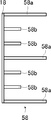
- FIG. 44 is a schematic cross-sectional view taken along line AA of the soundproof cell shown in FIG. 43. It is a top view of other examples of a soundproof member with a soundproof structure of the present invention.
- FIG. 46 is a schematic cross-sectional view of the soundproof member shown in FIG. 45 taken along line BB.
- FIG. 46 is a schematic cross-sectional view of the soundproof member shown in FIG. 45 taken along the line CC.
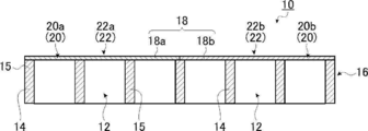
- FIG. 1 is a plan view schematically showing an example of a soundproof structure according to an embodiment of the present invention
- FIG. 2 is a schematic cross-sectional view taken along line II-II of the soundproof structure shown in FIG. is there.
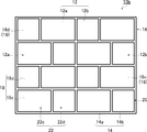
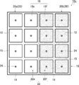
- 3 to 5 are plan views schematically showing an example of a soundproof structure according to another embodiment of the present invention.
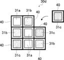
- the soundproof structure 10 of the present invention shown in FIGS. 1 and 2 has a plurality of (two) two-dimensionally arranged openings 16, each of which forms 36 frames 14 in the illustrated example, and each frame.
- the plurality (36 pieces) of the film 18 is composed of two types of films 18a and 18b, each having a plurality of thicknesses and / or 18 in the illustrated example, and having different thicknesses and / or types (physical properties such as Young's modulus and density).
- 20 is composed of sheet-like film bodies 20a and 20b that form a plurality (18 pieces) of films 18a and 18b, respectively.
- the soundproof structure 10 has a plurality of, in the illustrated example, 36 soundproof cells 22 arranged two-dimensionally.
- Each of the soundproof cells 22 includes a frame 14 and a film 18a, and includes a plurality of (18) soundproof cells 22a having a predetermined first resonance frequency, a frame 14 and a film 18b, and is different from the soundproof cell 22a.
- a plurality of (18) soundproof cells 22b having the first resonance frequency.
- These 18 soundproof cells 22a and 22b are arranged in 6 rows and 3 columns adjacent to the right and left sides in the figure, respectively.
- the first resonance frequency is the lowest-order resonance frequency of each soundproof cell 22a and 22b.
- the soundproof structure 10 of the present embodiment by using the films 18a and 18b having different thicknesses and / or types (physical properties), two types of soundproof cells 22a and 22b having different first resonance frequencies are formed. ing.
- the soundproof structure 10 of the present invention has a shielded peak frequency at which the transmission loss is maximized between the first resonance frequencies of the two kinds of soundproof cells 22a and 22b having different first resonance frequencies.
- the first resonance frequency of the two types of soundproof cells and the shielding peak frequency representing the shielding peak will be described later.
- the soundproof structure 10 in the illustrated example is constituted by two types of soundproof cells 22 (22a, 22b) having films having different thicknesses and / or types (physical properties), but the present invention is not limited to this. Instead, it may be composed of one soundproof cell 22a and 22b.
- a plurality (18) of soundproof cells 22a and a plurality (18) of soundproof cells 22b are gathered on both sides of one boundary line, and on the left and right in the illustrated example.
- the present invention is not limited to this, and the soundproof cell 22a and the soundproof cell 22b are arranged in a staggered manner as in the soundproof structure 10a shown in FIG. Also good.
- the plurality of soundproof cells 22a and 22b are continuously arranged in one different region of the two areas, respectively.
- the soundproof cells 22b are not continuous with each other, the soundproof cells 22b are arranged around the soundproof cells 22a (front and rear, left and right), and the soundproof cells 22a are arranged around the soundproof cells 22b (front and rear, right and left)
- this invention is not limited to this, You may arrange
- the soundproof cells 22a and 22b may be arranged in a mixed intermediate state. Further, like the soundproof structures 10 and 10a of the present invention, the number of soundproof cells 22a and 22b having different effective stiffnesses is preferably the same, but the present invention is not limited to this, and the shielding peak frequency described later is used. However, the number of the soundproof cells 22a and 22b may be different as long as it can be clearly present between the first resonance frequencies of two soundproof cells 22a and 22b described later.
- the film 18a of the soundproof cell 22a and the film 18b of the soundproof cell 22b have the same thickness and / or type (physical properties such as Young's modulus and density) of the film 18, as described above. Because of the difference, one soundproof cell 22a and the other soundproof cell 22b of the soundproof cell 22 of the frame-membrane structure in which the frame 14 and the film 18 are combined are of two types having different film rigidity as the frame-membrane structure. Frame-membrane structure.
- one structure exhibits a behavior on the mass law side and a sound wave transmitted through each other structure at a frequency at which the other structure behaves on the rigidity law side. Cancel each other, so that a strong sound insulation can be obtained in the soundproof structure 10 of the present embodiment.
- “stiffness” is determined not only by the Young's modulus, which is an index of the hardness of film properties, but also by the thickness of the film and / or the film type (film physical properties such as Young's modulus and density).
- the effective stiffness of the frame-membrane structure is not only the film thickness and / or film type (film physical properties such as Young's modulus and density), but also the size of the frame 14, that is, the opening 12 of the frame 14. Therefore, it may be determined by the size of the film 18 attached to the frame 14. In the example shown in FIG.
- soundproof cells 22 having a frame-membrane structure having films 18 (18a, 18b) having different effective stiffnesses, which are the soundproof cells 22a and 22b. It is not limited to this, and may be composed of three or more types of soundproof cells 22 having films 18 having different effective stiffnesses. Below, two types of soundproof cells are demonstrated as a representative example.
- the frame 14 is formed so as to be annularly surrounded by a frame member 15 that is a thick plate-like member, and has an opening 12 inside, and a film 18 (18a, 18a, 18) covers the opening 12 on at least one side.
- 18b In the following description, it is assumed that the reference numeral 18 is used except for the case where it is necessary to distinguish between the two), and the section of the membrane vibration of the membrane 18 fixed to the frame 14 It will be. Therefore, the frame 14 is higher in rigidity than the film 18. Specifically, both the mass and rigidity per unit area need to be high.
- the shape of the frame 14 is preferably a closed continuous shape that can fix the membrane 18 so that the entire outer periphery of the membrane 18 can be suppressed, but the present invention is not limited to this, and the frame 14 As long as it becomes a node of the membrane vibration of the membrane 18 fixed to the substrate, a part thereof may be cut and discontinuous. That is, the role of the frame 14 is to control the membrane vibration by fixing the membrane 18, so that even if there is a small cut in the frame 14 or there is a part that is not very slightly bonded, it is effective. Demonstrate.
- the shape of the opening 12 formed by the frame 14 is a planar shape, which is a square in the example shown in FIG. 1, but is not particularly limited in the present invention.
- Other quadrilaterals such as regular triangles, equilateral triangles, right triangles, polygons including regular polygons such as regular pentagons, regular hexagons, circles, ellipses, etc. It may be fixed.
- both ends of the opening 12 of the frame 14 are not closed, and both are open to the outside as they are.
- a film 18 is fixed to the frame 14 so as to cover the opening 12 at at least one end of the opened opening 12.
- the size of the frame 14 is a size in plan view, and can be defined as the size of the opening 12.
- the size of the frame 14 may be constant in all the frames 14 when two or more types of films 18 having different thicknesses and / or types (physical properties) are used. Although a frame having a different size (including a case where the shape is different) may be included, in this case, the average size of the frame 14 may be used as the size of the frame 14.
- the sizes of the frames 14 are different from each other as in the soundproof structure 10b shown in FIG. It may have two or more sizes.
- the soundproof structure 10b shown in FIG. 4 has a plurality of frame members 15 forming a rectangular opening 12a, eight frames 14a in the illustrated example, and the short side of the rectangular opening 12a as one side, and the size of the opening 12a is the same.
- a frame 16 having a plurality (16 pieces) of frames 14 consisting of a plurality of frame members 15 forming different square openings 12b, in the illustrated example, eight frames 14b, and openings 12a and all of all the frames 14a.
- the sheet-like film body 20 forms a plurality (16 pieces) of films 18 including a film 18c covering the opening 12a of the frame 14a and a film 18d covering the opening 12b of the frame 14b.
- the film 18c constitutes a soundproof cell 22c
- the frame 14b and the film 18d constitute a soundproof cell 22d.
- the frames 14a and 14b, and therefore, the film 18c and the film 18d form a rectangle and a square each having a common length, but the sizes of the frames 14a and 14b, and therefore
- the present invention is not limited to this as long as the size of the film 18 covering the opening 12 is different, and may be any shape or any size.
- the size of such a frame 14 is not particularly limited, and a soundproofing object to which the soundproofing structures 10, 10a, and 10b (hereinafter represented by the soundproofing structure 10) of the present invention are applied for soundproofing, for example, Copiers, blowers, air conditioners, ventilation fans, pumps, generators, ducts, and other industrial equipment such as coating machines, rotating machines, conveyors, etc. that emit sound, automobiles, trains, aircraft Set according to general household equipment such as transport equipment such as refrigerator, washing machine, dryer, television, copy machine, microwave oven, game machine, air conditioner, electric fan, PC, vacuum cleaner, air cleaner, etc. That's fine.
- the soundproof structure 10 itself can be used like a partition to be used for the purpose of blocking sounds from a plurality of noise sources.
- the size of the frame 14 can be selected from the frequency of the target noise.
- the soundproof structure 10 having the frame 14 and the film 18 and having two types of soundproof cells 22 (22a and 22b, 22c and 22d) having a frame-membrane structure having different effective stiffnesses.
- it is preferable to reduce the size of the frame 14.
- the average size of the frame 14 will be described in detail later, but in order to prevent sound leakage due to diffraction at the shielding peak of the soundproof structure 10 by the two types of soundproof cells 22 (22a and 22b, 22c and 22d), It is preferable that it is below the wavelength size corresponding to the shielding peak frequency mentioned later.
- the size of the frame 14 is preferably 0.5 mm to 200 mm, more preferably 1 mm to 100 mm, and most preferably 2 mm to 30 mm, even for the frames 14 a and 14 b having different sizes. preferable.
- the size of the frame 14 is the average size when different sizes are included in each frame 14. It may be expressed as
- the width and thickness of the frame 14 are not particularly limited as long as the film 18 can be fixed so as to surely suppress the film 18 and the film 18 can be reliably supported.
- the width and thickness are set according to the size of the frame 14. be able to.
- the width of the frame 14 is preferably 0.5 mm to 20 mm, more preferably 0.7 mm to 10 mm, and more preferably 1 mm to 5 mm when the size of the frame 14 is 0.5 mm to 50 mm. Most preferably. If the ratio of the width of the frame 14 to the size of the frame 14 becomes too large, the area ratio of the portion of the frame 14 occupying the whole increases, and there is a concern that the soundproof structure 10 as a device becomes heavy. On the other hand, if the ratio is too small, it is difficult to strongly fix the film with an adhesive or the like at the frame 14 portion.
- the width of the frame 14 is preferably 1 mm to 100 mm, more preferably 3 mm to 50 mm, and more preferably 5 mm to 20 mm when the size of the frame 14 is more than 50 mm and 200 mm or less. Most preferred.
- the thickness of the frame 14 is preferably 0.5 mm to 200 mm, more preferably 0.7 mm to 100 mm, and most preferably 1 mm to 50 mm. Note that the width and thickness of the frame 14 are preferably represented by an average width and an average thickness, respectively, when different widths and thicknesses are included in each frame 14.
- a plurality of, that is, two or more frames 14 are preferably configured as a frame body 16, preferably a single frame body 16, arranged so as to be two-dimensionally connected.
- the number of the frames 14 of the soundproof structure 10 of the present invention that is, in the illustrated example, the number of the frames 14 constituting the frame body 16 is 36.
- the number of the frames 14 may be set according to the size of the frame 14.
- the number of frames 14 is preferably 1 to 10000, more preferably 2 to 5000, and most preferably 4 to 1000 in the case of noise shielding in equipment.
- the size of the device is determined with respect to the size of a general device, and therefore the size of the pair of soundproof cells 22 (22a and 22b, 22c and 22d) is set to a size suitable for the noise frequency.
- the frame body 16 including a plurality of soundproof cells 22 In order to achieve this, it is often necessary to shield, i.e., reflect and / or absorb, the frame body 16 including a plurality of soundproof cells 22, and on the other hand, by increasing the number of soundproof cells 22, This is because the entire weight may increase.
- the number of frames 14 can be freely selected according to the required overall size.
- the number of the frames 14 of the soundproof structure 10 of the present invention is the number of the soundproof cells 22.
- metal materials such as aluminum, titanium, magnesium, tungsten, iron, steel, chromium, chromium molybdenum, nichrome molybdenum, and alloys thereof, acrylic resin, polymethyl methacrylate, polycarbonate, polyamideid, Resin materials such as polyarylate, polyetherimide, polyacetal, polyetheretherketone, polyphenylene sulfide, polysulfone, polyethylene terephthalate, polybutylene terephthalate, polyimide, triacetyl cellulose, carbon fiber reinforced plastics (CFRP: Carbon Fiber Reinforced Plastics) , Carbon fiber, glass fiber reinforced plastic (GFRP) and the like. Further, a plurality of types of materials of these frames 14 may be used in combination.
- CFRP Carbon Fiber Reinforced Plastics
- GFRP glass fiber reinforced plastic
- the film 18 is fixed to the frame 14 so as to cover the opening 12 inside the frame 14, and absorbs or reflects sound wave energy by vibrating the film in response to sound waves from the outside. Soundproofing. Therefore, the membrane 18 is preferably impermeable to air. By the way, since it is necessary for the membrane 18 to vibrate with the frame 14 as a node, the membrane 18 is fixed to the frame 14 so as to be surely suppressed, becomes an antinode of membrane vibration, and needs to absorb or reflect sound wave energy to prevent sound. There is. For this reason, the membrane 18 is preferably made of a flexible elastic material. Therefore, it can be said that the shape of the film 18 is the shape of the opening 12 of the frame 14 and the size of the film 18 is the size of the frame 14, more specifically, the size of the opening 12 of the frame 14. .
- the film 18 has two types of films 18 a and 18 b having different thicknesses and / or types (physical properties such as Young's modulus and density), or a frame size, and thus a size to be attached to the frame 14. It consists of two different types of films 18c and 18d.
- two kinds of soundproof cells 22 22a and 22b, 22c and 22d
- Two different types of membranes 18 (18a and 18b, 18c and 18d) fixed to the frame 14 (14a and 14b) each have the lowest transmission loss as the lowest natural vibration mode frequency (natural vibration frequency).
- the soundproof structures 10, 10a and 10b of the present invention have a maximum transmission loss between the two first resonance frequencies of the two types of films 18, that is, a shielding peak frequency that becomes a shielding peak.
- the soundproof structure of the present invention has two or more types of films having different sizes, thicknesses and / or types (physical properties), thereby having two or more types of soundproof cells having different first resonance frequencies.
- the shielding peak frequency at which the transmission loss is maximized is within a range that is not less than the lowest frequency among the first resonance frequencies of each soundproof cell and not more than the maximum frequency among the first resonance frequencies of each soundproof cell.
- the frame-membrane structure of the soundproof cell of the soundproof structure according to the present invention has the first resonance frequency, which is a frequency at which the sound wave is greatly transmitted due to resonance of the membrane surface.
- This first resonance frequency is determined by effective stiffness such as the above-described film thickness, film type (physical properties such as Young's modulus, density, etc.) and / or frame size (opening, film size).
- a stiffer structure has a resonance point at a higher frequency.
- this frame-membrane structure can be regarded as a connection between a capacitor (capacitor) and an inductance (coil).
- the wave amplitude is strengthened or canceled by interference.
- the phase-lag wave transmitted through the frame-membrane structure (soundproof cell) showing the rigidity law and the phase-advance wave transmitted through another frame-membrane structure (soundproof cell) showing the mass law are opposite in phase. Because it is oriented, it becomes a relationship of cancellation. Therefore, in the frequency region sandwiched between two first resonance frequencies of two different frame-membrane structures (soundproof cells), there is a canceling relationship, and in particular, the frequencies of the sound waves transmitted through the respective frame-membrane structures are equal. Then, the amplitudes of the waves are equal and the phases are inverted, and a very large shielding occurs.
- a frame-membrane structure that is two structures with different effective “stiffness”, for example, two types of membranes with the same frame but different thicknesses and / or two types of different physical properties Strong sound insulation can be achieved simply by applying a film.
- This is the principle of soundproofing of the soundproofing structure of the present invention.
- Such a feature of the present invention suffices if there are two or more types of frame-membrane structures (soundproof cells) having different rigidity, and the material and thickness of the membrane can be selected in various ways according to the application.
- a film having various characteristics can be used as a film to be attached to the frame, for example, other flame retardant, light transmissive, and / or heat insulating properties can be easily used.
- a soundproof structure having a function combined with physical properties or characteristics may be used.
- FIGS. 6 to 9 and FIGS. 18 to 19 described above are films having different thicknesses of the soundproof structure of the present invention, films having different physical properties, films having different sizes attached to frames having different sizes, and It is a graph which shows the simulation result of the sound insulation characteristic about the some combination of the film
- FIG. 10 and FIG. 13 are the sound insulation characteristics of the sound insulation structure of Example 1 of the sound insulation structure of this invention, and Example 2, respectively. Is a graph showing transmission loss with respect to frequency. The details of the simulation of the sound insulation characteristics of the soundproof structure of the present invention will be described later.
- the sound wave is the frequency at which the sound wave shakes the film vibration most due to the resonance phenomenon. This is the resonance frequency of the natural vibration mode that is largely transmitted.
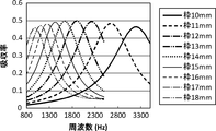
- FIG. 6 is a graph showing a simulation result of the sound insulation characteristics represented by transmission loss with respect to frequency for a plurality of combinations of films 18 (18a and 18b) having different thicknesses for the soundproof structure 10 shown in FIG.
- the size of the frame 14 is a square with a side of 20 mm
- the films 18a and 18b are PET (polyethylene terephthalate) films of the same type (same material and physical properties)
- the thickness of one film 18a is 100 ⁇ m. It shows the transmission loss when the thickness of the other film 18b is changed from 125 ⁇ m to 250 ⁇ m in increments of 25 ⁇ m.
- FIG. 6 shows the transmission loss when the thickness of the other film 18b is changed from 125 ⁇ m to 250 ⁇ m in increments of 25 ⁇ m.
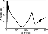
- the first resonance frequency of the soundproof cell 22 a including one 100 ⁇ m-thick film 18 a is about 830 Hz in the audible range where the transmission loss is 0 dB.
- the first resonance frequency of the soundproof cell 22b including the membrane 18b is about 1610 Hz in the audible range where the transmission loss is 0 dB, and the shielding is such that the transmission loss has a peak value of about 32 dB at about 1360 Hz between the first resonance frequencies. Therefore, a certain frequency band centered around 1360 Hz, which is the shielding peak frequency in the audible range, can be selectively shielded.
- FIG. 7 shows that in the soundproof structure 10 shown in FIG. 1, the size of the frame 14 is a square with a side of 25 mm, the film 18a and the film 18b are the same type of PET film, and the thickness of the film 18a is as thin as 50 ⁇ m.
- FIG. 6 is a graph showing a simulation result of sound insulation characteristics expressed by transmission loss with respect to frequency when the thickness of the other film 18b is changed from 80 ⁇ m to 120 ⁇ m in increments of 20 ⁇ m.
- both the first resonance frequencies of the soundproof cells 22a and 22b can be shifted to the lower frequency side compared to the example shown in FIG.
- a shielding peak frequency indicating a shielding peak can be taken.
- FIG. 6 and FIG. 7 are described as the sound insulation characteristics of the sound insulation structure 10 shown in FIG. 1.
- the sound insulation characteristics of the sound insulation structure 10a shown in FIG. 3 arranged in a staggered manner are the same as the sound insulation characteristics of the sound insulation structure 10 shown in FIG. It is confirmed in the embodiment described later that it is the same as FIG.
- the thickness of the film 18 can be set according to the size of the frame 14, that is, the size of the film.
- the thickness of the film 18 is preferably 0.005 mm (5 ⁇ m) to 5 mm, and preferably 0.007 mm (7 ⁇ m) to 2 mm when the size of the frame 14 is 0.5 mm to 50 mm.
- the thickness is 0.01 mm (10 ⁇ m) to 1 mm.
- the thickness of the film 18 is preferably 0.01 mm (10 ⁇ m) to 20 mm, and preferably 0.02 mm (20 ⁇ m) to 10 mm when the size of the frame 14 is more than 50 mm and 200 mm or less. Is more preferable, and 0.05 mm (50 ⁇ m) to 5 mm is most preferable. Note that the thickness of the film 18 is preferably expressed as an average thickness when the thickness of one film 18 is different, or when the thickness of each film 18 is different.
- FIG. 8 is a graph showing the simulation results of the sound insulation characteristics for a plurality of combinations of types 18, for example, films 18 (18 a and 18 b) having different Young's modulus, which are film properties, for the soundproof structure 10 shown in FIG. 1. .
- FIG. 8 shows that when the size of the frame 14 is a square with a side of 15 mm, the films 18a and 18b are PET films with a thickness of 100 ⁇ m, and the Young's modulus of one film 18b is 4.50 GPa, It represents the transmission loss when the Young's modulus is changed from 0.90 GPa to 4.50 GPa in increments of 0.90 GPa.
- the shielding peak frequency is on the lowest frequency side, the shielding peak is the highest, and as the Young's modulus of the film 18a increases, the first resonance frequency and the shielding peak frequency caused by the film 18a are It turns out that it shifts to the high frequency side and the peak of shielding becomes low.
- the film physical properties such as the Young's modulus of the film 18 of the soundproof cell 22 of the soundproof structure 10 different, a certain frequency band centered on the shielded peak frequency in the audible range can be selectively shielded.
- the shielding peak frequency existing between the two first resonance frequencies depending on the different films 18a and 18b is within the audible range.
- FIG. 18 is a graph showing a simulation result of the sound insulation characteristics represented by transmission loss with respect to frequency for a plurality of combinations of films 18 (18a and 18b) having different tensions for the soundproof structure 10 shown in FIG. .
- the size of the frame 14 is a square having a side of 20 mm
- the film 18 is a PET film
- the thickness of the film 18 is 100 ⁇ m
- a constant tension 130 (only for the film 18a, for example, only the film 18a.
- N / m) represents the transmission loss.
- the first resonance frequency of the soundproof cell 22a including the other membrane 18b to which no tension is applied is about 830 Hz in the audible range where the transmission loss becomes 0 dB as described above.
- the first resonance frequency of the soundproof cell 22a including the membrane 18a is about 1100 Hz in the audible range where the transmission loss is 0 dB, and the transmission loss has a peak value of about 38 dB at about 960 Hz between the first resonance frequencies. Since the peak of the shielding is shown, it is possible to selectively shield a certain frequency band centered on the shielding peak frequency of 960 Hz in the audible range.
- one frame-membrane structure complies with the rigidity law and the other frame-membrane structure obeys the mass rule, and two second films 18a and 18b fixed to the frame 14 are used.
- the two first resonance frequencies by the films 18a and 18b are both 10 Hz to 100,000 Hz corresponding to the human sound wave sensing range. It is more preferably 20 Hz to 20000 Hz, which is the audible range of the sound wave, still more preferably 40 Hz to 16000 Hz, and most preferably 100 Hz to 12000 Hz.
- the first resonance frequencies of the films 18a and 18b in the structure composed of the frame 14 and the film 18 (18a and 18b) are the geometric forms of the frames 14 of the plurality of soundproof cells 22.
- it can be determined by the shape and size (size) of the frame 14 and the rigidity of the films 18 (18a and 18b) of the plurality of soundproof cells 22, for example, physical properties such as film thickness and flexibility.
- this ratio [a 2 / t] is equal, for example, (t, a) is (50 ⁇ m, 7. 5 mm) and (200 ⁇ m, 15 mm)
- the first natural vibration mode has the same frequency, that is, the same first resonance frequency. That is, by setting the ratio [a 2 / t] to a constant value, the scaling rule is established, and an appropriate size can be selected.
- the film 18 should have elasticity capable of vibrating the membrane in order to absorb or reflect sound wave energy to prevent sound.
- the Young's modulus of the film 18 (18a and 18b) can be set according to the size of the frame 14, that is, the size of the film 18.
- the Young's modulus of the film 18 (18a and 18b) is preferably 1000 Pa to 3000 GPa, more preferably 10,000 Pa to 2000 GPa, and most preferably 1 MPa to 1000 GPa.
- the film 18 (18a and 18b) is not particularly limited as long as the film can vibrate in order to absorb or reflect sound wave energy to prevent sound.
- the film 18 (18a and 18b) is not particularly limited as long as the film can vibrate in order to absorb or reflect sound wave energy to prevent sound.
- the film 18 When the material of the film 18 is a film-like material or a foil-like material, the film 18 has strength suitable for application to the above-described soundproofing object, and is resistant to the soundproofing environment of the soundproofing object. As long as the film can vibrate in order to absorb or reflect sound wave energy to prevent sound, it is not particularly limited and can be selected according to the soundproof object and its soundproof environment.
- the material of the film 18 includes polyethylene terephthalate (PET), polyimide, polymethyl methacrylate, polycarbonate, acrylic (PMMA), polyamideide, polyarylate, polyetherimide, polyacetal, polyetheretherketone, polyphenylene sulfide, polysulfone.
- the film 18 may be individually fixed to each of the plurality of frames 14 of the frame body 16 of the soundproof structure 10 to constitute a sheet-like film body 20 as a whole.
- Each film 18 covering each frame 14 may be formed by one sheet-like film body 20 fixed so as to cover the frame. That is, the plurality of films 18 may be constituted by a single sheet-like film body 20 that covers the plurality of frames 14. Alternatively, as an intermediate between them, a sheet-like film body is fixed to a part of the frames 14 so as to cover a part of the plurality of frames 14, and a film 18 that covers each frame 14 is formed. You may comprise the sheet-like film body 20 which covers the whole some frame 14 (all the frames 14) using some bodies.
- the film 18 is fixed to the frame 14 so as to cover the opening on at least one side of the opening 12 of the frame 14. That is, the film 18 may be fixed to the frame 14 so as to cover the opening on one side, the other side, or both sides of the opening 12 of the frame 14.
- all the films 18 may be provided on the same side of the openings 12 of the plurality of frames 14 of the soundproof structure 10, or some of the films 18 may be one of the openings 12 of some of the plurality of frames 14.
- a part of the film 18 may be provided on the other side, and the other part of the remaining part of the openings 12 of the plurality of frames 14 may be provided on the other side.
- membrane provided in one side, the other side, and both sides may be mixed.
- the method for fixing the film 18 to the frame 14 is not particularly limited, and any method may be used as long as the film 18 can be fixed to the frame 14 so as to be a node of membrane vibration.
- a method using an adhesive or a physical And a method using a simple fixing tool.
- the adhesive is applied on the surface surrounding the opening 12 of the frame 14, the film 18 is placed thereon, and the film 18 is fixed to the frame 14 with the adhesive.
- adhesives examples include epoxy adhesives (Araldite (registered trademark) (manufactured by Nichiban Co., Ltd.)), cyanoacrylate adhesives (Aron Alpha (registered trademark) (manufactured by Toagosei Co., Ltd.), etc.), acrylic adhesives, etc. Can be mentioned.
- a film 18 disposed so as to cover the opening 12 of the frame 14 is sandwiched between the frame 14 and a fixing member such as a rod, and the fixing member is a fixing tool such as a screw or a screw.
- a method of fixing the frame 14 to the frame 14 by using the above can be used.
- FIG. 9 is a graph showing simulation results of sound insulation characteristics for a plurality of combinations of frames 14 (14a and 14b) having different sizes of the soundproof structure 10b shown in FIG.
- the film 18 (18c and 18d) is a PET film having a thickness of 100 ⁇ m
- the size of the frame 14a, and hence the size of the opening 12a and the film 18c is a square 3 of 20 mm ⁇ 15 mm, 20 mm, and 30 mm on one side.
- FIG. 9 shows that the film 18 (18c and 18d) is a PET film having a thickness of 100 ⁇ m
- the size of the frame 14a, and hence the size of the opening 12a and the film 18c is a square 3 of 20 mm ⁇ 15 mm, 20 mm, and 30 mm on one
- the first resonance frequency of the soundproof cells 22c and 22d due to the films 18c and 18d appears in the same vicinity of about 1200 Hz, but the shielding No peak appears, and it can be seen that the soundproof structure of the present invention is not obtained.
- the soundproof cell 22c is more effective than the soundproof cell 22d. The resonance frequency shifts to the high frequency side.
- the soundproof cell 22c is less effective than the soundproof cell 22d.
- the first resonance frequency of the soundproof cell 22c is shifted to the low frequency side. In this way, by changing the size of the frame 14 (membrane 18) of the soundproof cell 22 of the soundproof structure 10b, it is possible to selectively cut off a certain frequency band centered on the shield peak frequency in the audible range. .
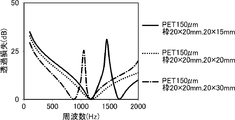
- FIG. 19 is a graph showing a simulation result of the sound insulation characteristic represented by the transmission loss with respect to the frequency for the combination of the three kinds of films 18 having different stiffnesses in the soundproof structure of the present invention.
- FIG. 19 shows transmission loss when the size of the frame 14 is a square with a side of 20 mm, the film 18 is a PET film, and the thickness of the film 18 is 100 ⁇ m, 150 ⁇ m, and 200 ⁇ m.
- the first resonance frequency of the soundproof cell 22 having the thickness of the membrane 18 of 100 ⁇ m is about 830 Hz in the audible range where the transmission loss is 0 dB as described above, and the soundproofing having the thickness of the membrane 18 of 150 ⁇ m.
- the first resonance frequency of the cell 22 is about 1150 Hz in the audible range where the transmission loss is 0 dB, and the first resonance frequency of the soundproof cell 22 in which the thickness of the film 18 is 200 ⁇ m is in the audible range where the transmission loss is 0 dB.
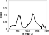
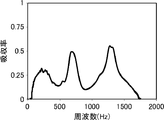
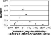
- each of the first and second embodiments of the soundproof structure of the present invention shown in FIGS. Since two first resonance frequencies due to the cells (22a and 22b) appear, and between these two first resonance frequencies, a shielding peak frequency at which the transmission loss is maximized appears at 1000 Hz to 1300 Hz in the audible range. It shows that a certain frequency band centered on each shielding peak frequency can be selectively sound-insulated.
- the sound absorption rate is maximized in the vicinity of two first resonance frequencies corresponding to two different types of soundproof cells (22a and 22b). As a result, broadband sound absorption is achieved.
- the measuring method of the transmission loss (dB) and the absorptance in the Example of the soundproof structure of this invention is mentioned later.
- the membrane 18 (including 18a and 18b and 18c and 18d) seals the opening 12 (including 12a and 12b) of the frame 14 (including 14a and 14b).
- this invention is not limited to this, Size, thickness, and / or kind (physical property etc.) differ like the soundproof structure 10c of embodiment shown in FIG.
- One or more through holes 24 may be formed in the film 18 made of the films 18e and 18f.
- the soundproof structure 10 c of the present embodiment including the different soundproof cells 22 e and 22 f shown in FIG. 5 is also the soundproof structure 10, 10 a shown in FIGS.
- the thickness, type (physical properties) and / or the size of the frame 14 are made different from each other regardless of the presence or absence of the through hole 24.
- the first resonance frequency appears in each of the soundproof cells 22e and 22f, and a transmission loss peak where the shielding becomes a peak (maximum) appears between these two first resonance frequencies, and this shielding (transmission loss) is the peak.
- the frequency that becomes (maximum) is the shielding peak frequency.
- the through holes 24 are provided on the lower frequency side than the first resonance frequency on the low frequency side.
- the soundproof structure 10c of the present embodiment not only has the shielding peak between the two first resonance frequencies by the two types of soundproof cells 22 having different effective stiffnesses, but also the first on the low frequency side. Since there is a new shielding peak due to the through hole 24 on the lower frequency side than the resonance frequency, the sound insulation can be improved.
- one or more through holes 24 may be perforated in the film 18 (18 e and 18 f) covering the opening 12 of the soundproof cell 22 (22 e and 22 f). Further, the drilling position of the through hole 24 may be in the middle of the membrane 18, that is, the soundproof cell 22 (hereinafter, represented by the soundproof cell 22) as shown in FIG. 5, but the present invention is not limited to this. First, as shown in FIG. 5, it does not need to be in the middle of the soundproof cell 22, and may be perforated at any position. That is, simply changing the drilling position of the through hole 24 does not change the sound insulation characteristic of the soundproof structure 10c of the present embodiment.
- the through hole 24 is preferably perforated in a region within a range exceeding 20% of the dimension of the surface of the membrane 18 from the fixed end of the peripheral edge of the opening 12. Most preferably, it is provided.
- the number of through holes 24 in the soundproof cell 22 may be one for one soundproof cell 22, but the present invention is not limited to this. It may be more than one (that is, a plurality).
- the through hole 24 of each soundproof cell 22 is comprised with one through hole 24. As shown in FIG. The reason is that, when the aperture ratio is constant, the ease of passage of air as wind is greater when one hole is large and the viscosity at the boundary does not work greatly.
- the sound insulation characteristic of the soundproof structure 10 c of the present embodiment shows a sound insulation characteristic corresponding to the total area of the plurality of through holes 24. Therefore, the total area of the plurality of through holes 24 in one soundproof cell 22 (or film 18) is equal to the area of the through hole 24 having only one in another soundproof cell 22 (or film 18).
- the present invention is not limited to this.
- the aperture ratio of the through holes 24 in the soundproof cell 22 the total area ratio of all the through holes 24 to the area of the film 18 covering the openings 12 (the ratio of the total area of all the through holes 24)
- the same soundproof structure 10 c is obtained with the single through hole 24 and the plurality of through holes 24, various soundproof structures can be produced even if they are fixed to a certain size of the through hole 24.
- the aperture ratio (area ratio) of the through holes (all through holes) 24 in the soundproof cell 22 is not particularly limited, and may be appropriately set according to the sound insulation characteristics. It is preferably from ⁇ 70%, more preferably from 0.000005% to 50%, and preferably from 0.00001% to 30%. By setting the aperture ratio of all the through holes 24 within the above range, it is possible to appropriately adjust the sound insulation peak frequency and the sound transmission loss of the sound insulation peak, which are the center of the sound insulation frequency band to be selectively insulated.
- the soundproof structure 10c of this embodiment preferably has a plurality of through holes 24 of the same size in one soundproof cell 22 from the viewpoint of manufacturability. That is, it is preferable to drill a plurality of through holes 24 of the same size in each soundproof cell 22. Furthermore, in the soundproof structure 10c of the present embodiment, it is preferable that the through holes 24 of all the soundproof cells 22 have the same size.
- the through hole 24 is preferably drilled by a processing method that absorbs energy, for example, laser processing, or is preferably drilled by a machining method by physical contact, for example, punching or needle processing. .
- a processing method that absorbs energy for example, laser processing
- a machining method by physical contact for example, punching or needle processing.
- holes are formed by laser processing, punching, or needle processing.
- the size (size) of the through hole 24 in the soundproof cell 22 (or film 18) is the same for each soundproof cell 22 (or film 18).
- the size of the through hole 24 is not particularly limited as long as it can be appropriately drilled by the above-described processing method.
- the size of the through hole 24 is, on the lower limit side, from the viewpoint of manufacturing suitability such as laser processing accuracy such as laser aperture accuracy, processing accuracy such as punching processing or needle processing, and ease of processing. It is preferably 2 ⁇ m or more, more preferably 5 ⁇ m or more, and most preferably 10 ⁇ m or more. Since the upper limit value of the size of these through holes 24 needs to be smaller than the size of the frame 14, the size of the frame 14 is usually on the order of mm, and the size of the through hole 24 can be set on the order of ⁇ m. For example, the upper limit value of the size of the through hole 24 does not exceed the size of the frame 14, but if it exceeds, the upper limit value of the size of the through hole 24 may be set to be equal to or smaller than the size of the frame 14. .
- the film 18 is fixed to the frame 14 so as to cover the opening on one side of the opening 12 of the frame 14, but the present invention is not limited to this, and is shown in FIG.
- a soundproof cell hereinafter also referred to as a first soundproof cell 22h in which a film 18g is provided only on one side of the opening 12 of the frame 14, and on both sides of the opening 12 of the frame 14
- the soundproof cell (first soundproof cell) 22j provided with the film 18i only on one side of the opening 12 of the 14 and the frame size different from the soundproof cell 22j provided on both sides of the opening 12 of the frame 14, that is, the film A film 18j having a size different from that of 18i is provided.
- Soundproof cell may be made of (second soundproof cell) 22k.
- films 18 (18 a and 18 b, 18 c and 18 d, 18 e and 18 f) having different thicknesses, types (physical properties) and / or film sizes from each other are framed 14.
- a two-dimensionally arranged combination of two types of soundproof cells having different first resonance frequencies covering one side of the opening 12 of the film like the soundproof structure 10d of the embodiment shown in FIG.
- the soundproof cell 22i having a layer) film may be combined. Further, as shown in the soundproof structure 10e of the embodiment shown in FIG. 23, the soundproof cell 22j provided with a soundproof cell in which the film 18i covers only one of the openings 12 of the frame 14, that is, a single layer film (single layer film); The film 18j may be a combination of a soundproof cell covering both sides of the opening 12 of the frame 14, that is, a soundproof cell 22k having a two-layer film (multilayer film). In the example shown in FIGS. 22 and 23, the soundproof cells 22j and 22k have a two-layer film, but the present invention is not limited to this, and the soundproof cell has a multilayer film of two or more layers. It may be a cell.
- FIGS. 22 and 23 is a combination of the soundproof cell 22 of the single layer film 18 and the soundproof cell 22 (22h and 22i, 22j and 22k) of the double layer film 18 having different first resonance frequencies. , Utilizing such an action.
- the first resonance frequency of one layer of the soundproof cell (first soundproof cell) 22h or 22j and the soundproof cell (second soundproof cell) 22j or 22k The frame size, the frame thickness, and the distance between the two layers (between the films) are adjusted so that the higher-order resonance frequencies match. Specifically, among the first resonance frequency of one layer of the soundproof cell (first soundproof cell) 22h or 22j and the resonance frequency of the higher order mode of the soundproof cell (second soundproof cell) 22j or 22k, 2 The film thickness, the frame size, the frame thickness, and the distance between two layers (between films) are adjusted so that the resonance frequency of the resonance mode in which the displacement of the layer film moves in the opposite direction is matched.
- the first soundproof cell includes the first soundproof cell and the second soundproof cell by matching the first resonance frequency of the first soundproof cell with the higher-order resonance frequency of the second soundproof cell.
- the soundproof structure in which the second soundproof cell and the second soundproof cell are disposed adjacent to each other has a specific frequency indicating the maximum absorption rate of sound at a specific frequency, that is, the maximum absorption rate.
- a specific frequency indicating the maximum absorption rate can be referred to as a maximum absorption frequency.
- the maximum absorption frequency is a higher-order resonance frequency of the second soundproof cell or substantially equal to a higher-order resonance frequency of the second soundproof cell.
- the first resonance frequency of the first soundproof cell and the higher-order resonance frequency of the second soundproof cell match means that the first resonance frequency of the first soundproof cell and the second soundproofing cell. It is preferable that the difference (shift) from the higher-order resonance frequency of the cell is within ⁇ 1/3 of the higher-order resonance frequency of the second soundproof cell. The difference between the first resonance frequency of the first soundproof cell and the higher order resonance frequency of the second soundproof cell is within ⁇ 1/7 of the higher order resonance frequency of the second soundproof cell. More preferably, it is more preferably within ⁇ 1/17, and most preferably within ⁇ 1/33.
- the soundproof structure including the first soundproof cell and the second soundproof cell has a maximum absorption frequency at which the maximum sound absorption rate is obtained, that is, when the second-order resonance frequency of the second soundproof cell is 1650 Hz, for example, ⁇ 550 Hz Within ⁇ 250 Hz, more preferably within ⁇ 100 Hz, even more preferably within ⁇ 100 Hz, and most preferably within ⁇ 50 Hz.
- the soundproof structures 10d and 10e of the embodiment shown in FIGS. 22 and 23 have two types of soundproof cells (22h and 22h) as in the embodiments 10, 10a, 10b and 10c shown in FIGS. Since the first resonance frequencies 22i, 22j and 22k) are different, a shielding peak frequency at which the transmission loss is maximized can be generated between the first resonance frequencies of the two types of soundproof cells.
- the soundproof structures 10d and 10e of the embodiment shown in FIGS. 22 and 23 are similar to the soundproof structures 10, 10a, 10b and 10c of the embodiment shown in FIGS. 1 to 5 of the soundproof cells 22h and 22i.
- the frequency becomes the shielding peak frequency.
- the soundproof structures 10d and 10e of the embodiment shown in FIGS. 22 and 23 cause one peak of the transmission loss, and in addition, one soundproof cell of two types of soundproof cells having different first resonance frequencies, that is, one layer.
- the two match.
- the higher frequency for example, the higher order resonance frequency of the other soundproof cell, it is possible to obtain a sound absorption rate far exceeding 50% that cannot be achieved by a soundproof structure consisting of a single soundproof cell. Can be achieved. That is, the soundproof structures 10d and 10e of the embodiment shown in FIGS.
- the 22 and 23 are designed so that the first resonance frequency of the one-layer film matches the higher-order resonance frequency of the two-layer film. Even if the frame size or frame thickness of the soundproof cell frame and the distance between the two layers (films) are less than 1/4 of the wavelength of the sound wave, the sound absorption rate far exceeds 50%. can do. In particular, in the soundproof structure 10d of the embodiment shown in FIG. 22, even if the frame size or frame thickness of the soundproof cell is less than 1/10 of the wavelength of the sound wave, the sound absorption rate is 90% or more. Can be achieved.
- 2 and R
- the sound absorptance of a single-layer film structure is usually 50% or less. Also in the case of a two-layer film structure, if the distance between two layers (between films) is much smaller than the wavelength of sound, specifically, less than 1/4, the transmitted wave Since it is difficult to make the phases cancel each other, the sound absorption rate remains at about 50%. This is because, in FIG. 25 showing the sound absorption characteristics of the soundproof structure of Example 5, which will be described later, the first resonance frequency corresponding to the soundproof cell 22i having two layers of films exists at 760 Hz. It can also be seen from the fact that the absorptivity is about 50%. As described above, according to the soundproof structure of the present embodiment, it is possible to obtain the sound absorption rate far exceeding the conventional absorption rate only by changing the frame size or adjusting the frame thickness.
- the film 18h-1 and the film 18h-2 of the soundproof cell 22i are configured with the same film thickness, but the present invention is not limited to this, and films with different film thicknesses are used. You can also.
- the film 18i of the soundproof cell 22i, the film 18j-1 and the film 18j-2 of the soundproof cell 22k are all the same film thickness, but the present invention is not limited to this.
- the film 18i and 18j-2 that cover one side of the opening 12 of the frame 14 of the two soundproof cells need only have the same film thickness, and the film thickness of the soundproof cell 18j-1 is equal to the film 18i and 18j ⁇ . It may be different from the film thickness of 2.
- two or more first resonance frequencies are applied to the film 18 having the frame-membrane structure including the frame 14 and the film 18.
- the shielding peak frequency at which the transmission loss reaches a peak is determined by two or more types of soundproof cells 22 in which at least one of the thickness, the type of film 18 (physical properties), and the size of the frame 14 (size of the film 18) is different. It depends on the effective stiffness of the cell 22.
- the inventors of the present invention provide the circle 14 of the frame 14 (14a, 14b) in the soundproof cells 22 (22a, 22b, 22c, 22d, 22e, 22f) of the soundproof structures 10, 10a, 10b, and 10c of the present invention.
- the equivalent radius is R (m)
- the thickness of the film 18 (18a, 18b, 18c, 18d, 18e, 18f) is t (m)
- the Young's modulus of the film 18 is E (Pa)
- the density of the film 18 is d (kg).
- the first resonance frequency (Hz) of the cell 22 is the equivalent circle radius R (m) of the soundproof cell 22, the thickness t (m) of the film 18, the Young's modulus E (Pa) of the film 18, and the density d ( kg / m 3 ) is changed in a substantially linear relationship as shown in FIG. As shown in FIG. 21, it has been found that it is represented by the formula represented by the following formula (2).
- B t / R 2 * ⁇ (E / d) (1)
- y 0.7278x 0.9566 (2)
- y is the first resonance frequency (Hz)
- x is the parameter B.
- FIG. 20 shows a first resonance frequency (Hz) and a parameter B for a soundproof cell 22 comprising a frame 14 having openings 12 having various opening shapes and sizes, and a film 18 having physical properties such as various thicknesses, densities and Young's modulus.
- the points representing the relationship between the parameter B and the first resonance frequency (Hz) of the soundproof structure are plotted on the substantially same straight line, and the above equation (which can be regarded as a substantially linear equation) ( 2).
- FIG. 2 shows a substantially linear equation
- FIG. 21 shows the first resonance frequency (Hz) and parameters for one soundproof cell 22 comprising a frame (square frame) 14 having a square shape of the soundproof structure of the present invention shown in Tables 1 to 3 and a film 18.
- B represents an exponent display with a base of 10.
- 1.00E-04 represents 1.00 ⁇ 10 ⁇ 4 .
- the soundproof structure of the present invention is provided with a soundproof cell 22 composed of a square-shaped frame (square frame) 14 and a film 18, the parameter B and the first resonance frequency (Hz) of the soundproof structure. It can be understood that it can be said that the point representing the relationship with is on the same straight line as the straight line represented by the above formula (2) which can be regarded as a substantially linear expression shown in FIG.
- the equivalent circle radius R (m) of the soundproof cell 22 the thickness t (m) of the film 18, the Young's modulus E (Pa) of the film 18, and the density d of the film 18
- the point representing the relationship between the parameter B and the first resonance frequency (Hz) of the soundproof structure 10 on the two-dimensional (xy) coordinates is It is expressed by the above formula (2) that can be regarded as a substantially linear expression, and it can be seen that all the points are on substantially the same straight line.
- Table 1 shows parameter B values for a plurality of values of the first resonance frequency between 10 Hz and 10 5 (100,000) Hz.
- the parameter B corresponds to the first resonance frequency. Therefore, in the present invention, the parameter B is preferably 15.47 (1.547 ⁇ 10) or more and 2.350 ⁇ 10 5 or less. 31.94 (3.194 ⁇ 10) to 4.369 ⁇ 10 4 , more preferably 65.92 (6.592 ⁇ 10) to 3.460 ⁇ 10 4 , Most preferably, it is 171.8 (1.718 ⁇ 10 2 ) to 2.562 ⁇ 10 4 .
- the first resonance frequency of the soundproof cell on one side which is the lower limit on the low frequency side of the shield peak frequency, and the shield peak frequency
- the first resonance frequency of a different soundproof cell on the other side which is the upper limit on the high frequency side
- the shielding peak frequency that is the center of the frequency band to be selectively sound-insulated can be determined.
- the soundproofing of the present invention having two or more different first resonance frequencies that can have a shielding peak frequency at the center of a frequency band to be selectively sound-insulated. You can set the structure.
- the soundproof structure of the present invention Since the soundproof structure of the present invention is configured as described above, it enables low-frequency shielding, which has been difficult in the conventional soundproof structure, and further adapts to noise of various frequencies from low frequencies to frequencies exceeding 1000 Hz. It also has the feature that it can design a structure that provides strong sound insulation. In addition, since the soundproof structure of the present invention is a sound insulation principle that does not depend on the mass (mass law) of the structure, it is possible to realize a very light and thin sound insulation structure compared to the conventional soundproof structure. Therefore, it can be applied to a soundproofing object for which sufficient sound insulation is difficult.
- the soundproof structure of the present invention compared with most conventional sound insulation materials and sound insulation structures, requires a heavy sound insulation structure due to shielding by the mass law, but it may be a simple frame-membrane structure. Can be lightened.
- the soundproof structure of the present invention can obtain a strong shielding peak without using a weight that needs to be attached later with an adhesive as in the technique described in Patent Document 2, and has a simpler configuration. .
- the soundproof structure of the present invention does not require a weight in the frame-membrane structure, as in the technique described in Patent Document 2, and is suitable for manufacturing only by making the film or the frame different, and has high robustness as a sound insulating material. It has the characteristic of being a structure.
- Patent Document 2 performs sound insulation on the structural mechanical principle that the average value of membrane vibration in a unit cell is 0, the soundproof structure of the present invention vibrates the membrane itself, The sound insulation peak is caused by the acoustic wave dynamic principle that the sound is extinguished by the interference of the transmitted sound wave, so the principle is completely different, and the sound of any specific frequency, particularly the sound on the low frequency side, can be selectively erased .
- the soundproof structure of the present invention performs sound insulation by a technique that does not exist in the technique described in Patent Document 1 in which a strong sound insulation peak is generated and the target frequency is erased. It can be said that there is a great performance improvement that a strong shielding peak can be aimed at an arbitrary frequency by changing.
- the soundproof structure of the present invention uses a technique of performing sound insulation by combining a plurality of cells, various sound insulations can be achieved compared to the conventional technique in which a sound insulation effect is produced by a device in one unit cell. Adaptable and versatile.
- it is not necessary to add an extra structure such as a weight as a technique for strongly shielding an arbitrary frequency in the audible range from low to medium frequencies. Since it is composed of a frame-membrane structure, it has excellent manufacturing suitability and is advantageous from the viewpoint of cost.
- the soundproofing effect is determined by the hardness, density, and / or thickness of the film, and does not depend on other physical properties.
- radio wave transmission the combination of a frame material with no electrical conductivity such as acrylic and a dielectric film ensures radio wave transmission, while the frame material with a high electrical conductivity such as aluminum or a metal film covers the entire surface. Thus, radio waves can be shielded.
- the film is preferably flame retardant.
- the film include Lumirror (registered trademark) non-halogen flame retardant type ZV series (manufactured by Toray Industries, Inc.), Teijin Tetron (registered trademark) UF (manufactured by Teijin Limited), and / or flame retardant, which are flame retardant PET films.
- the frame is also preferably a flame retardant material, such as a metal such as aluminum, an inorganic material such as a semi-rack, a glass material, a flame retardant polycarbonate (for example, PCMUPY 610 (manufactured by Takiron)), and / or slightly difficult.
- flame retardant plastics such as flammable acrylic (for example, Acrylite (registered trademark) FR1 (manufactured by Mitsubishi Rayon Co., Ltd.)).
- the method of fixing the film to the frame includes a flame-retardant adhesive (ThreeBond 1537 series (manufactured by ThreeBond)), a soldering method, or a mechanical fixing method such as sandwiching and fixing the film between two frames. preferable.
- the material constituting the structural member is preferably heat resistant, particularly low heat shrinkable.
- Teijin Tetron (registered trademark) film SLA manufactured by Teijin DuPont
- PEN film Teonex registered trademark
- Lumirror registered trademark
- a metal film such as aluminum having a smaller coefficient of thermal expansion than the plastic material.
- the frame is made of a heat-resistant plastic such as polyimide resin (TECASINT4111 (manufactured by Enzinger Japan)) and / or glass fiber reinforced resin (TECAPEEKGF30 (manufactured by Enzinger Japan)), and / or aluminum. It is preferable to use an inorganic material such as a metal or ceramic, or a glass material.
- the adhesive is also a heat-resistant adhesive (TB3732 (manufactured by ThreeBond), a super heat-resistant one-component shrinkable RTV silicone adhesive sealant (manufactured by Momentive Performance Materials Japan), and / or a heat-resistant inorganic adhesive Aron. Ceramic (registered trademark) (manufactured by Toa Gosei Co., Ltd.) is preferably used.
- TB3732 manufactured by ThreeBond
- Ceramic registered trademark
- the amount of expansion and contraction can be reduced by setting the thickness to 1 ⁇ m or less.
- the membrane is a special polyolefin film (Art Ply (registered trademark) (manufactured by Mitsubishi Plastics)), an acrylic resin film (Acryprene (manufactured by Mitsubishi Rayon)), and / or Scotch film (trademark) (manufactured by 3M).
- the frame material is preferably made of a plastic having high weather resistance such as polyvinyl chloride or polymethylmethacryl (acrylic), a metal such as aluminum, an inorganic material such as ceramic, and / or a glass material.
- a plastic having high weather resistance such as polyvinyl chloride or polymethylmethacryl (acrylic), a metal such as aluminum, an inorganic material such as ceramic, and / or a glass material.
- an adhesive having high weather resistance such as epoxy resin and / or Dreiflex (manufactured by Repair Care International).
- the moisture resistance it is preferable to appropriately select a film, a frame, and an adhesive having high moisture resistance. In terms of water absorption and chemical resistance, it is preferable to select an appropriate film, frame, and adhesive as appropriate.
- a fluororesin film (Dynock Film (trademark) (manufactured by 3M)) and / or a hydrophilic film (Miraclean (manufactured by Lifeguard)), RIVEX (manufactured by Riken Technos), and / or SH2CLHF (manufactured by 3M) )
- Miraclean manufactured by Lifeguard
- RIVEX manufactured by Riken Technos
- SH2CLHF manufactured by 3M
- the use of a photocatalytic film (Laclean (manufactured by Kimoto)) can also prevent the film from being soiled. The same effect can be obtained by applying a spray containing these conductive, hydrophilic and / or photocatalytic properties and / or a spray containing a fluorine compound to the film.
- a cover on the film.
- a thin film material such as Saran Wrap (registered trademark)
- Saran Wrap registered trademark
- a mesh having a mesh size that does not allow passage of dust, a nonwoven fabric, urethane, airgel, a porous film, or the like can be used.
- the soundproof structure 10c having the through hole 24 serving as a ventilation hole in the film 18 as shown in FIG. 5 the soundproof members 30a and 30b shown in FIG. 35 and FIG.
- the cover 32 provided in the above is provided with a hole 34 so that wind and dust do not directly hit the film 18.
- the dust can be removed by emitting a sound having a resonance frequency of the film and strongly vibrating the film. The same effect can be obtained by using a blower or wiping.
- Wind pressure When the strong wind hits the film, the film is pushed and the resonance frequency may change. Therefore, the influence of wind can be suppressed by covering the membrane with a nonwoven fabric, urethane, and / or a film.
- the cover 32 provided on the film 18 is also provided with a hole 34 so that the wind does not directly hit the film 18.
- the soundproof structures 10, 10a, 10b, and 10c of the present invention shown in FIGS. 1 to 5 are configured by a single frame 16 in which a plurality of frames 14 are continuous, but the present invention is not limited to this, It may be a soundproof cell as a unit unit cell having one frame and one film attached thereto, or having a through-hole formed in the one frame, one film and the film. That is, the soundproofing member having the soundproofing structure of the present invention does not necessarily need to be configured by one continuous frame, and has a frame structure and a film structure attached thereto as a unit unit cell, or one frame.
- It may be a soundproof cell having a structure and a single membrane structure and a hole structure formed in the membrane structure, and such unit unit cells are used independently or a plurality of unit unit cells are used in combination. You can also.
- a magic tape registered trademark; hereinafter the same
- magnets magnets, buttons, suction cups, and / or uneven portions may be attached to the frame body portion.
- a plurality of unit unit cells can also be connected using a tape or the like.
- the soundproof member may be attached with a desorption mechanism comprising a magnetic body, a magic tape, a button, a sucker, and the like.
- a desorption mechanism comprising a magnetic body, a magic tape, a button, a sucker, and the like.
- the attachment / detachment mechanism 36 is attached to the bottom surface of the outer frame 14 of the frame 16 of the soundproofing member 30c, and the attachment / detachment mechanism 36 attached to the soundproofing member 30c is attached to the wall 38 to provide soundproofing.
- the member 30c may be attached to the wall 38, or, as shown in FIG. 38, the detaching mechanism 36 attached to the soundproof member 30c is detached from the wall 38, and the soundproof member 30c is detached from the wall 38. Also good.
- the soundproofing characteristics of the soundproofing member 30d are adjusted by combining the soundproofing cells 31a, 31b and 31c having different resonance frequencies, for example, as shown in FIG.
- And 31c are preferably attached to each soundproof cell 31a, 31b, and 31c with a detaching mechanism 40 such as a magnetic material, a velcro tape, a button, or a suction cup.
- a detaching mechanism 40 such as a magnetic material, a velcro tape, a button, or a suction cup.
- the soundproof cell 31d is provided with a convex portion 42a
- the soundproof cell 31e is provided with a concave portion 42b
- the convex portion 42a and the concave portion 42b are engaged with each other.
- the soundproof cell 31d and the soundproof cell 31e may be detached. As long as a plurality of soundproof cells can be combined, one soundproof cell may be provided with both convex portions and concave portions. Furthermore, the soundproof cell may be attached and detached by combining the above-described detaching mechanism 40 shown in FIG. 39 with the concavo-convex portion, convex portion 42a and concave portion 42b shown in FIG.
- FIGS. 45 to 47 by changing or combining the frame thickness in the plane, high rigidity can be ensured and the weight can be reduced.
- FIG. 45 As in the soundproof member 52 having the soundproof structure of the present invention shown in FIG. 45, as shown in FIG. 46, which is a cross-sectional schematic view of the soundproof member 52 shown in FIG.
- the frame members 58a on both outer sides and the center of the frame body 58 including a plurality of frames 56 are made thicker than the other frame members 58b.
- FIG. 45 which is a cross-sectional schematic view of the soundproof member 52 shown in FIG.
- each soundproof cell shown in FIGS. 37 to 47 is not provided with a through hole, but the present invention is not limited to this, and the soundproof cell 22 of the embodiment shown in FIG. Of course, the through hole 24 may be provided.
- the weight which is a factor that increases the mass is not necessary as compared with the technique described in Patent Document 2, as described above.
- a lighter sound insulation structure it has the following features. 1. Since the film can be punched at high speed and easily by laser processing or punch holes, it has manufacturability. 2. Since the sound insulation characteristics hardly depend on the position and shape of the hole, stability in manufacturing is high. 3. The presence of the hole makes it possible to realize a structure in which the membrane has air permeability, that is, a sound is shielded while passing wind and heat.
- the soundproof structure 10 of the present invention shown in FIG. 1 is manufactured as follows. First, a frame body 16 having a plurality of, for example, 225 frames 14, a sheet-like film body 20 a covering all the openings 12 of the half frames 14 of all the frames 14, and the remaining half frames 14. A sheet-like film body 20b having a thickness different from that of the film body 20a and covering all the openings 12 is prepared. Next, a sheet-like film body 20a is adhered and fixed to the half frame 14 of all the frames 14 of the frame body 16 with an adhesive, and a film 18a covering each of the openings 12 of the half frame 14 is formed. A plurality of soundproof cells 22a having a structure composed of the frame 14 and the film 18a are formed.
- a sheet-like film body 20b is affixed and fixed to the remaining half frame 14 of all the frames 14 of the frame body 16 with an adhesive, and a film 18b that covers each of the openings 12 of the remaining half frame 14 is formed.
- a plurality of soundproof cells 22b having a structure composed of the frame 14 and the film 18b are formed.
- the soundproof structure 10 of the present invention can be manufactured.
- the film 18a and the film 18b are attached to the frame 14 so as to form a staggered arrangement, and in the case of the soundproof structure 10 of the present invention shown in FIG. Different.
- a frame body 16 having a frame 14 having a different frame size and a sheet-like film body 20 are prepared, and the frame size of the frame body 16 is prepared. 1 is different from the case of the soundproof structure 10 of the present invention shown in FIG.
- a laser is applied to each of the film 18a of the half soundproof cell 22a and the film 18b of the other half of the soundproof cell 22b of the soundproof structure 10 of the present invention shown in FIG.
- One or more through holes 24 are respectively drilled by a machining method that absorbs energy such as machining, or a mechanical machining method such as punching or needle machining, and the through holes 24 are formed in each soundproof cell 22. .
- the soundproof structure of the present invention is basically configured as described above.
- the soundproof structure of the present invention can be used as the following soundproof member.
- Soundproof material for building materials Soundproof material used for building materials
- Sound-proofing material for air-conditioning equipment Sound-proofing material installed in ventilation openings, air-conditioning ducts, etc.
- Soundproof member for external opening Soundproof member installed in the window of the room to prevent noise from inside or outside the room
- Soundproof member for ceiling Soundproof member that is installed on the ceiling in the room and controls the sound in the room
- Soundproof member for floor Soundproof member that is installed on the floor and controls the sound in the room
- Soundproof member for internal openings Soundproof member installed at indoor doors and bran parts to prevent noise from each room
- Soundproof material for toilets Installed in the toilet or door (indoor / outdoor), to prevent noise from the toilet
- Soundproof material for balcony Soundproof material installed on the balcony to prevent noise from your own balcony or the adjacent balcony
- Indoor sound-adjusting member Sound-proofing member for controlling the sound of the room
- Simple soundproof room material Soundproof material that can be easily assembled and moved easily.
- Soundproof room members for pets Soundproof members that surround pet rooms and prevent noise
- Amusement facilities Game center, sports center, concert hall, soundproofing materials installed in movie theaters
- Soundproof member for temporary enclosure for construction site Soundproof member to prevent noise leakage around the construction site
- Soundproof member for tunnel Soundproof member that is installed in a tunnel and prevents noise leaking inside and outside the tunnel can be mentioned.
- the soundproof structure of the present invention will be specifically described based on examples.
- the design of the soundproof structure by simulation will be described before the experiment of manufacturing the embodiment of the present invention and measuring the acoustic characteristics. Since this soundproof structure system is an interaction system between membrane vibration and sound waves in the air, analysis was performed using a coupled analysis of sound and vibration. Specifically, the design was performed using an acoustic module of COMSOL ver5.0 which is analysis software of the finite element method. First, the first resonance frequency was obtained by natural vibration analysis. Next, acoustic structure coupling analysis by frequency sweep was performed in the boundary of the periodic structure, and transmission loss at each frequency with respect to the sound wave incident from the front was obtained. Based on this design, the shape and material of the sample were determined. The shielding peak frequency in the experimental result and the predicted shielding peak frequency from the simulation agreed well as in the experimental result and the simulation result of Example 1 shown in FIG.
- the correspondence between the first resonance frequency and each physical property was obtained by taking advantage of the characteristics of the simulation that can freely change the material characteristics and the film thickness.
- the thickness t (m) of the film 18 By changing the thickness t (m) of the film 18, the size (or radius) R (m) of the frame 14, the Young's modulus E (Pa) of the film, and the density d (kg / m 3 ) of the film as parameters B Asked.
- the results are shown in FIGS.
- Example S1 First, regarding the simulation of the soundproof structure 10 of the present invention in which two types of PET films having different thicknesses as the film 18 are fixed to the 20 mm frame 14, the PET film of one film 18a is 100 ⁇ m, and the PET film of the other film 18b is 125, 150.
- the transmission loss for thicknesses of 175, 200, 225, and 250 ⁇ m is shown in FIG.
- the size of the frame 14 is a square of 20 mm
- the first resonance frequency of the soundproof cell 22a of the PET film 100 ⁇ m of the one film 18a is 800 Hz
- the first resonance of the soundproof cell 22b of the PET film having a different thickness of the other film 18b The frequency is on the higher frequency side, and a maximum value of transmission loss appears at an intermediate frequency.
- the frequency indicating the maximum value is the shielding peak frequency. From FIG. 6, as described above, in the soundproof structure 10 of the present invention, when the PET film of the other film 18b becomes thicker, the first resonance frequency on the high frequency side shifts to the higher frequency side, and the shielding peak frequency also increases on the higher frequency side. It can be seen that the peak of shielding increases.
- the size of the frame 14 is a 25 mm square
- the film thickness of the PET film of one film 18a is 50 ⁇ m
- the size of the frame 14 is 25 mm.
- One resonance frequency was set to a low frequency.
- a simulation was performed by combining a 25 mm square frame 14 and a PET film having a thickness of 80, 100, or 120 ⁇ m on the other film 18b, and the frequency dependence of transmission loss was obtained. The results are shown in FIG. It was found that the maximum value of transmission loss appears even on the low frequency side where the frequency is between 300 Hz and 500 Hz. From FIG. 7, it can be seen that the soundproof structure 10 of the present invention shows the same tendency as in FIG. 6 even when the film thickness of the PET film is reduced as a whole.
- Example S3 a combination of a PET film having a thickness of 100 ⁇ m with a film 18 a and a film having a Young's modulus set with a thickness of 100 ⁇ m of the film 18 b in a 15 mm square frame 14 was calculated.
- the set Young's modulus was 0.9, 1.8, 2, 7, 3.6, 4.5 GPa, and other Poisson's ratio and density parameters were the same as those of the PET film of the film 18a.
- the Young's modulus of the PET film itself was 4.5 GPa.
- the first resonance frequency when the film 18b has a low Young's modulus is on the low frequency side.
- the PET film frame-film structure of the film 18a A maximum value of transmission loss appeared between the first resonance frequency and the first resonance frequency.
- the Young's modulus was equal to 4.5 GPa between the film 18a and the film 18b, only one first resonance frequency appeared, and no shielding peak frequency appeared. From FIG.
- Example S4 As a simulation when the areas of the frame 14 are different, a structure having two types of unit frames, a 20 mm square square frame 14 b and a square frame 14 a with a side 20 mm ⁇ a side x mm (x is 15, 20, and 30 mm, respectively). A simulation was performed in which a PET film having a thickness of 150 ⁇ m was fixed as the film body 20 (films 18e and 18f).
- Example S5 In order to see the effect of tension, the transmission loss of a model in which tension was applied to one soundproof cell 22 was calculated by the above-described COMSOL.
- the size of the frame 14 of the soundproof cell 22 is a 20 mm square
- the thickness of the film 18 is 100 ⁇ m
- a constant tension 130 (N / m) is applied only to the film 18 of the soundproof cell 22 on one side, for example 18a.
- the material of the film 18 is the physical property value of a PET film.
- the transmission loss obtained from the calculation result is shown in FIG.
- first resonance frequencies There are two transmission loss minimum values (first resonance frequencies) corresponding to the natural vibrations of the cell structure of each of the soundproof cells 22 (22a, 22b), and a large transmission loss peak appears in the frequency between them.
- first resonance frequencies By applying the tension of the film 18 (18a) of the soundproofing cell 22 (22a), the first resonance frequency is shifted from the first resonance frequency of the original cell structure of the soundproofing cell 22 (22b) to which no tension is applied. Therefore, it was shown that even if the soundproof cells originally have the same properties, the first resonance frequencies are different between the soundproof cells having different tensions, and a strong transmission loss appears at the frequency between them.
- Example S6 In order to see the effect when the hardness of three or more types of membranes is different, the transmission loss of the soundproof cell 22 having a frame-membrane structure having three levels of membrane thickness was calculated by the above-mentioned COMSOL.
- the size of the frame 14 of all the soundproof cells 22 of the model is a square shape of 20 mm square, and the thickness of each film 18 is 100 ⁇ m, 150 ⁇ m, and 200 ⁇ m, and the periphery of the film 18 is fixedly restrained to the frame 14.
- the material of the film 18 is the physical property value of a PET film.
- the transmission loss obtained from the calculation result is shown in FIG.
- Example 1 First, as shown in FIG. 1, a soundproof structure 10 having soundproof cells 22a and 22b having a structure in which the films 18a and 18b are PET films of 100 ⁇ m and 188 ⁇ m, respectively, and the size of the frame 14 is 20 mm square was manufactured. The creation procedure is shown below. As the films 18a and 18b, 100 ⁇ m and 188 ⁇ m PET films (Toray Industries, Inc.) were used.
- the frame 14 aluminum having a thickness of 3 mm ⁇ width of 2 mm was used, and the shape of the frame 14 was set to a square, and one processed by setting one side of the square opening 12 to 20 mm was used.
- the opening 12 which penetrates a frame structure has a total of 36 of 6x6 pieces.
- a 100 ⁇ m thick PET film is fixed to 3 ⁇ 6 frame regions with an adhesive, and then a 188 ⁇ m thick PET film is bonded to the remaining 3 ⁇ 6 frame regions.
- a soundproof structure 10 shown in FIG. 1 having two kinds of soundproof cells having a frame-film structure composed of a frame and two kinds of films was produced.
- the acoustic characteristics were measured by the transfer function method using four microphones in a self-made aluminum acoustic tube. This method follows “ASTM E2611-09: Standard Test Method for Measurement of Normal Incidence Sound Transmission of Acoustical Materials Based on the Transfer Matrix Method”.
- the acoustic tube has the same measurement principle as, for example, WinZac manufactured by Nittobo Acoustic Engineering Co., Ltd. With this method, sound transmission loss can be measured in a wide spectral band.
- the soundproof structure 10 having a frame-membrane structure was placed at the measurement site of the acoustic tube, and the sound transmission loss was measured in the range of 100 Hz to 2000 Hz. The measurement results of the transmission loss are shown in FIGS.
- FIGS. 10 and 17 there are two different first resonance frequencies corresponding to the two types of soundproof cells at about 800 Hz and about 1400 Hz, respectively. It was found that extremely strong shielding occurs at a shielding peak frequency near 1300 Hz. At the shielding peak frequency of 1284 Hz, the peak value of the transmission loss at the shielding peak frequency was 24 dB.
- Example 1 using the transmittance and reflectance measured in Example 1, the frequency dependence of the sound absorption rate of Example 1 was determined.
- the results are shown in FIG.
- FIG. 10 In the soundproof structure of the first embodiment, as shown in FIG. 10, there are two different first resonance frequencies corresponding to the two types of soundproof cells. However, as shown in FIG. It can be seen that there is a maximum absorptance at one resonance frequency, and as a result, broadband sound absorption is achieved.
- the sound transmission loss of the soundproof structure having the configuration of Example 1 was obtained by simulation in the range of 100 Hz to 2000 Hz.
- the simulation result is shown in FIG.
- FIG. 12 shows the measurement results of the transmission loss by the experiment shown in FIG. As shown in FIG. 12, it can be seen that the measurement result of the transmission loss by the experiment and the prediction result of the transmission loss by the simulation are in good agreement.
- a sample preparation method is shown.
- Example 1 In Example 1 described above, instead of using two types of membranes, one of them, a 188 ⁇ m-thick PET film, was fixed to 6 ⁇ 6 frame regions with an adhesive. The sound transmission loss was measured for the soundproof structure having this single type of soundproof cell. Sound insulation by general mass law and rigidity law was obtained.
- FIG. 17 shows the measurement result of the transmission loss of Comparative Example 1.
- FIG. 17 shows the frequency dependence of the shielding coefficient of Comparative Example 1.
- Comparative Example 2 In Example 1 above, instead of using two types of films, a PET film having a thickness of 100 ⁇ m, which is the other one of the films, was fixed to 6 ⁇ 6 frame regions with an adhesive. The sound transmission loss was measured for the soundproof structure having this single type of soundproof cell.
- FIG. 17 shows the measurement result of the transmission loss of Comparative Example 2.
- FIG. 17 also shows the frequency dependence of the shielding coefficient of Comparative Example 2.
- the soundproof structure of Comparative Example 2 has a smaller film thickness, and thus less stiffness. For this reason, as shown in FIG. 17, the first resonance frequency appeared on the lower frequency side as compared with Comparative Example 1.
- FIG. 17 shows the frequency dependence of the shielding coefficient, which is a measurement result of all the shielding loss in Example 1, Comparative Example 1, and Comparative Example 2. From FIG. 17, it can be seen that in the vicinity of 1300 Hz, the PET 188 ⁇ m soundproof cell of Comparative Example 1 exhibits the rigidity law, and the PET 100 ⁇ m soundproof cell of Comparative Example 2 exhibits the behavior of the mass law. When the transmission amplitudes from the two soundproof cells are equal, a large shielding peak appears in the structure of the first embodiment comprising the two soundproof cells. This shows that the transmitted waves from the two types of soundproof cells cancel each other out, and a great sound insulation effect is obtained.
- Example 2 the soundproof structure 10 having the soundproof cells 22a and 22b of the structure in which the films 18a and 18b shown in FIG. 1 are PET films of 100 ⁇ m and 250 ⁇ m, respectively, and the size of the frame 14 is 25 mm square was manufactured.
- Lumirror was used as the PET film of the films 18a and 18b as in Example 1.
- the frame 14 as in Example 1, an aluminum thickness of 3 mm ⁇ width of 2 mm was used, and the shape of the frame 14 was a square and one side of the square opening 12 was processed with a side of 25 mm.
- the opening 12 that penetrates the frame structure has a total of 16 4 ⁇ 4.
- FIG. 13 the measurement result of the transmission loss of Example 2 was shown. Moreover, the obtained sound absorption coefficient of the sound of Example 2 is shown in FIG.
- the soundproof structure of the second embodiment as shown in FIG. 13, there are two different first resonance frequencies corresponding to the two kinds of soundproof cells at about 600 Hz and about 1300 Hz, respectively. It was found that extremely strong shielding occurred in a frequency region centered on the shielding peak frequency near 1100 Hz. At the shielding peak frequency of 1100 Hz, the peak value of the transmission loss at the shielding peak frequency was 30 dB.
- FIG. 14 in the soundproof structure of Example 2, the maximum of the absorption factor resulting from the two types of first resonance frequencies of the two types of soundproof cells 22a and 22b also appeared in this case.
- Example 3 A through hole 24 having a diameter of 1 mm was formed in the film 18 of each soundproof cell 22 having the soundproof structure of Example 2 described above.
- the through hole 24 was dynamically formed using a punch. It was confirmed using an optical microscope that the diameter of the through hole 24 was 1 mm.
- the soundproof structure 10c having the soundproof cells 22e and 22f with through holes 24 having different effective stiffness schematically shown in FIG. 5 was formed.
- the acoustic measurement was performed in the same manner as in Example 1.
- FIG. 15 shows the measurement results of transmission loss.
- the two first resonance frequencies of about 600 Hz and about 1300 Hz due to the two different film thicknesses found in Example 2 remain, and the vicinity of 1100 Hz, which is the shielding peak frequency between the first resonance frequencies, remains.
- the shielding peak also remained, and the peak value of the transmission loss was 24 dB at a shielding peak frequency of 1150 Hz.
- a new shielding peak due to the provision of the through hole 24 occurred on the low frequency side.
- the shielding peak due to the through hole 24 appeared in the vicinity of 400 Hz, and a transmission loss of 25 dB was shown as the shielding peak value at 380 Hz.
- the transmission loss at 380 Hz was 12 dB.
- the result of the measurement of the sound absorption rate is shown in FIG. Also in this case, the maximum of the absorption factor due to the two first resonance frequencies of the two types of soundproof cells appeared, and the embodiment was further implemented in a lower frequency region than the shielding peak on the low frequency side due to the provision of the through hole. Absorption that was not in 2 also appeared.
- Example 4 With the same combination of film thicknesses as in Example 1, the soundproof cells 22 having different film thicknesses are arranged differently for each soundproof cell, as in the soundproof structure 10a shown in FIG. A sample having a checkered pattern in which the soundproof cells 22 having different film thicknesses were arranged was produced.
- the transmission loss and the sound absorption rate were measured in the same manner as in Example 1.
- the size of the 6 ⁇ 3 structure of the soundproof cell 22 is less than the wavelength in the current frequency measurement range also in the first embodiment, and therefore in the structure of the first embodiment and the structure of the fourth embodiment.
- the basic unit of size is less than the wavelength, diffraction and scattering do not occur, and it is considered that the function of the sound wave did not change because the structure was coarse-grained when viewed from the sound wave.
- a soundproof structure 10 d composed of soundproof cells 22 h and 22 i of a structure in which the thickness (frame thickness) L 1 of the frame 14 is 15 mm and the size (frame size) of the frame 14 is 20 mm each square.
- the PET film film 18g is edge-fixed with an adhesive so as to cover one side of the opening 12 of the frame 14, and then, both sides of the opening 12 of the frame 14 are covered.
- the soundproof structure 10d having two types of soundproof cells 22h and 22i is manufactured by fixing the edge of the PET film film 18h with an adhesive so that the distance between the two layers (between the films) is 15 mm. did.
- a PET film having a thickness (film thickness) of 188 ⁇ m was used for the film 18g, and a PET film having a thickness (film thickness) of 100 ⁇ m was used for the film 18h.
- the frame thickness, frame size, and film thickness described above are designed so that the first resonance frequency of the soundproof cell 22h matches the higher-order resonance frequency of the soundproof cell 22i.
- the sound insulation characteristics were measured in the same manner as in Example 1. This sound insulation characteristic is obtained by measuring a transmission loss at each frequency with respect to a sound wave incident from below in FIG.
- Example 5 the measurement result of the transmission loss of Example 5 was shown.
- the calculated sound transmittance, reflectance, and absorption rate of Example 5 are shown in FIG.
- the first resonance frequency corresponding to the soundproof cell 22h exists at 1410 Hz
- the first resonance frequency corresponding to the soundproof cell 22i exists at 760 Hz. It was found that a large transmission loss with a peak of shielding occurred in the vicinity of 1090 Hz.
- Example 5 produced a large transmission loss of 30 dB or more in the vicinity of 1410 Hz as shown in FIG. This is because a shielding peak appears at a frequency at which the first resonance frequency of the soundproof cell 22h matches the high (2) order resonance frequency of the soundproof cell 22i. From the reflectance and absorptance in the vicinity of a frequency of 1410 Hz shown in FIG. 25, this transmission loss is not caused by large reflection but is caused by large absorption, and the absorptance reaches 93% at the maximum. I understood it.
- the wavelength of 1410 Hz at which this maximum absorption rate is obtained is approximately 240 mm. It was found that a very high sound absorption rate was achieved with a size of less than 10.
- FIG. 26 shows the result of analyzing the sound insulation characteristics by simulation for each of the sound insulation structure 10d and the sound insulation cells 22h and 22i of Example 5.
- the analysis was performed using the acoustic module of COMSOLver5.0 which is the analysis software of the finite element method described above.
- the soundproof structure 10d of Example 5 is designed so that the first resonance frequency of the soundproof cell 22h matches the higher-order resonance frequency of the soundproof cell 22i.
- the absorption rate of each of the soundproof cell 22h and the soundproof cell 22i is only about 50%, but by arranging these two soundproof cells next to each other to form the soundproof structure 10d, the absorption rate is about 90%. Was shown to be.
- the acoustic structure interaction is calculated by coupling the transmission of sound waves and the vibration of the structure. Therefore, the vibration behavior of the diaphragm is also calculated from the structure calculation, and the pressure and the direction of the local velocity at each position can be output from the sound wave calculation.
- FIG. 27 shows the film displacement and its schematic diagram that occur when a sound wave is incident on the soundproof structure 10d from the direction indicated by the arrow, that is, from the lower side of FIG. 22, and FIG. 28 shows its local velocity.
- the vibration of the film in the normal first resonance frequency mode that is, large vibration in the center of the film 18g due to the incident sound pressure.
- a resonance mode film displacement occurs in which the displacement of the two-layer film 18h moves in the opposite direction due to the incident sound pressure.
- the film 18g and the film 18h-1 are arranged on the sound wave output side, that is, the sound wave incident direction. This is because the phase of the sound wave is reversed on the opposite side, and the wave transmitted through the film 18h-1 and the wave transmitted through the film 18h-2 interfere with each other between the film 18h-1 and the film 18h-2. . Also from FIG. 28, the sound wave transmitted through the film 18g of the soundproof cell 22h is inverted in phase and incident on the film 18h-2 of the soundproof cell 22i, and the sound wave transmitted through the film 18h-1 is canceled and transmitted. You can see that the waves get smaller.
- the size of the frame 14 is 14 mm each square, the other is the size of the frame 14 (frame size) 20 mm each square, and the frame thickness L 2 is 10 mm for both.
- the soundproof cell 22j is created by edge-fixing the PET film film 18i with an adhesive so as to cover one side of the opening 12 of the frame 14 with respect to this frame structure.
- the soundproof cell 22k was produced by edge-fixing the PET film film 18j with an adhesive so as to cover both sides of the 12 and the distance between the two layers (between the films) was 10 mm.
- the films 18i and 18j were both PET films having a thickness (film thickness) of 100 ⁇ m. Therefore, after the adhesive is applied to the frame, the part that hits the film 18i and the part that hits the film 18j-1 can be created simply by attaching them so as to cover the whole with the same PET film.
- the above-described frame thickness, frame size, and film thickness are designed so that the first resonance frequency of the soundproof cell 22j matches the higher-order resonance frequency of the soundproof cell 22k.
- FIG. 29 shows the result of analysis of sound insulation characteristics by simulation for the soundproof structure 10e of Example 6.
- the analysis was performed using the acoustic module of COMSOLver5.0 which is the analysis software of the finite element method described above. According to FIG. 29, it can be seen that, similarly to the result of Example 5, the sound absorption rate of the soundproof structure 10e of Example 6 shows an absorption rate of 82%, far exceeding 50%.
- FIG. 30 shows the film displacement that occurs when sound waves are incident on the soundproof structure 10e from the direction indicated by the arrow, that is, from the lower side of FIG. 23, and FIG. 31 shows the local velocity.
- the soundproof cell 22j having one layer (single layer) film similarly to the result of the soundproof structure 10d of the fifth embodiment, in the soundproof cell 22j having one layer (single layer) film, the displacement of the film in the normal first resonance frequency mode, that is, the incident sound Due to the pressure, a large vibration state is generated at the center of the film 18i.
- the displacement of the resonance mode film in which the displacement of the two-layer film 18j moves in the opposite direction due to the incident sound pressure is generated.
- the sound wave transmitted through the film 18i of the soundproof cell 22j is inverted in phase and incident on the film 18j-2 of the soundproof cell 22k, and cancels out the sound wave transmitted through the film 18j-1. It can be seen that the transmitted wave becomes smaller.
- Table 5 summarizes the structural conditions of the soundproof structures of Examples 5 and 6. As shown in Table 5, by appropriately setting the frame thickness, layer structure, frame size and film thickness of the two types of soundproof cells, the soundproof structure of the present invention has a sound absorption rate far exceeding 50%. Can be realized.
- Example 7 Next, as shown in Table 6, the soundproof cell (first soundproof cell) when the frame size of the soundproof cell 22j of the soundproof structure 10e of Example 6 shown in FIG. 23 is changed in increments of 1 mm from 10 to 18 mm. The first resonance frequency of each soundproof cell was determined. Further, as shown in FIG. 23, a soundproof structure in which each soundproof cell (first soundproof cell) and soundproof cell (second soundproof cell) 22k are disposed adjacent to each other is prepared, and the maximum absorption rate of the sound is obtained. I asked for each. The results are shown in Table 6. FIG. 32 shows each absorption spectrum of each produced soundproof cell (first soundproof cell). FIG.
- each soundproof cell is based on Table 6, the frame size of each soundproof cell (first soundproof cell), and the soundproof structure in which each soundproof cell (first soundproof cell) and soundproof cell (second soundproof cell) 22k are arranged adjacent to each other.
- Each graph shows the relationship between the maximum absorption rate of sound and the sound.
- the absorption rate is about 50% and maximum when the frame size is 12 to 14 mm, but does not increase beyond 50%. I understand that.
- an absorption factor will be 50% of the maximum in frequency 1650Hz.
- the maximum absorption rate of 82% was confirmed in all of the manufactured soundproof structures.
- the soundproof cell (first soundproof cell) and the second soundproof cell with a frame size of 14 mm were confirmed.
- the cell 22k is adjacent to the soundproof structure, and the first resonance frequency of the first soundproof cell is 1650 Hz. That is, this indicates that the second (2) order resonance frequency of the second soundproof cell 22k is also 1650 Hz.
- the difference (deviation) between the first resonance frequency of each manufactured first soundproof cell and the maximum absorption frequency at which the soundproof structure exhibits the maximum absorption rate for example, 1650 Hz, which is the higher-order resonance frequency of the second soundproof cell. Is shown in Table 6.
- the maximum sound absorption rate of the soundproof structure is the difference between the first resonance frequency of the first soundproof cell and the higher order resonance frequency of the second soundproof cell from which the maximum absorption rate of the soundproof structure is obtained. It was found that the (displacement) is symmetric about positive and negative with the maximum absorption rate of “0” as the center, and the smaller the difference (deviation), the greater the absorption rate.
- the soundproof structure of the present invention including the simulation examples S1 to S6 and the experimental examples 1 to 7, is different from the comparative examples 1 and 2, and has two types of effective stiffness. Since there are two different first resonance frequencies of the soundproofing cell, and there is a shielding peak at which the transmission loss peaks at the shielding peak frequency between these two first resonance frequencies, the shielding peak frequency is the center. The frequency band of a certain width can be selectively insulated. As is clear from the results of Examples 5 to 7 shown in FIGS.
- the soundproof structure of the present invention includes two types of soundproof cells having different first resonance frequencies.
- the soundproof structure of the present invention has an excellent sound insulation characteristic of being able to shield the specific frequency component aimed at very strongly, and can further increase the absorption of the component on the lower frequency side. I understood. From the above, the effect of the soundproof structure of the present invention is clear.
Abstract
L'invention fournit une structure d'insonorisation qui possède une pluralité de cellules d'insonorisation disposée en deux dimensions, chacune de ces cellules d'insonorisation est équipée : d'un cadre qui est constitué d'un matériau de cadre dans lequel est formée une ouverture ; et d'une membrane fixée sur le cadre. Parmi la pluralité de cellules d'insonorisation, des cellules d'insonorisation d'au moins deux sortes présentant des premières fréquences de résonance différentes, existent. La structure d'insonorisation présente une fréquence pic de blindage telle qu'un indice d'affaiblissement acoustique est extrême à l'intérieur d'une plage supérieure ou égale à la fréquence minimum parmi les premières fréquences de résonance de toutes les cellules d'insonorisation, et inférieure ou égale à la fréquence maximum parmi les premières fréquences de résonance de toutes les cellules d'insonorisation. Ainsi, la structure d'insonorisation est légère et fine, et présente une solidité élevée en tant que matériau d'isolation phonique indépendamment de caractéristiques d'isolation phonique telles que la fréquence de blindage, la dimension, ou similaire. En outre, la structure d'insonorisation est stable, s'adapte à une application à un appareil, à une automobile et à une maison ordinaire, et présente une excellente aptitude à la fabrication.
Priority Applications (2)
| Application Number | Priority Date | Filing Date | Title |
|---|---|---|---|
| JP2017524922A JP6570633B2 (ja) | 2015-06-22 | 2016-06-21 | 防音構造、及び防音構造の製造方法 |
| US15/802,784 US10704255B2 (en) | 2015-06-22 | 2017-11-03 | Soundproof structure and soundproof structure manufacturing method |
Applications Claiming Priority (4)
| Application Number | Priority Date | Filing Date | Title |
|---|---|---|---|
| JP2015124639 | 2015-06-22 | ||
| JP2015-124639 | 2015-06-22 | ||
| JP2016090881 | 2016-04-28 | ||
| JP2016-090881 | 2016-04-28 |
Related Child Applications (1)
| Application Number | Title | Priority Date | Filing Date |
|---|---|---|---|
| US15/802,784 Continuation US10704255B2 (en) | 2015-06-22 | 2017-11-03 | Soundproof structure and soundproof structure manufacturing method |
Publications (1)
| Publication Number | Publication Date |
|---|---|
| WO2016208580A1 true WO2016208580A1 (fr) | 2016-12-29 |
Family
ID=57584964
Family Applications (1)
| Application Number | Title | Priority Date | Filing Date |
|---|---|---|---|
| PCT/JP2016/068392 WO2016208580A1 (fr) | 2015-06-22 | 2016-06-21 | Structure d'insonorisation, et procédé de fabrication de celle-ci |
Country Status (3)
| Country | Link |
|---|---|
| US (1) | US10704255B2 (fr) |
| JP (1) | JP6570633B2 (fr) |
| WO (1) | WO2016208580A1 (fr) |
Cited By (7)
| Publication number | Priority date | Publication date | Assignee | Title |
|---|---|---|---|---|
| CN108385849A (zh) * | 2017-11-14 | 2018-08-10 | 同济大学 | 三维双声阻抗微穿孔周期超宽频带表面平齐吸声结构 |
| WO2018151067A1 (fr) * | 2017-02-14 | 2018-08-23 | 富士フイルム株式会社 | Structure insonorisée |
| CN108978128A (zh) * | 2017-05-31 | 2018-12-11 | 青岛海尔智能技术研发有限公司 | 一种洗衣机的降噪装置的设计方法 |
| WO2019074061A1 (fr) * | 2017-10-11 | 2019-04-18 | 富士フイルム株式会社 | Structure d'insonorisation en forme de boîtier et unité de transport |
| CN110588683A (zh) * | 2019-08-16 | 2019-12-20 | 哈工大机电工程(嘉善)研究院 | 一种面向厢体结构低频宽带降噪的复合板 |
| JPWO2019093202A1 (ja) * | 2017-11-07 | 2020-11-19 | 富士フイルム株式会社 | 防音構造体 |
| EP3751557A4 (fr) * | 2018-02-06 | 2021-03-31 | Fujifilm Corporation | Structure d'insonorisation |
Families Citing this family (23)
| Publication number | Priority date | Publication date | Assignee | Title |
|---|---|---|---|---|
| JP6043407B2 (ja) | 2015-02-27 | 2016-12-14 | 富士フイルム株式会社 | 防音構造、及び防音構造の製造方法 |
| EP3550558B1 (fr) * | 2016-11-29 | 2021-09-15 | FUJIFILM Corporation | Structure d'insonorisation |
| CN110235195B (zh) * | 2017-02-08 | 2020-06-09 | 富士胶片株式会社 | 防音结构体及开口结构体 |
| EP3761305A4 (fr) * | 2018-02-27 | 2021-04-21 | FUJIFILM Corporation | Structure d'insonorisation |
| CN108417195B (zh) * | 2018-06-13 | 2023-11-10 | 山东理工大学 | 一种基于共振腔的中低频吸声超材料结构 |
| WO2020013784A2 (fr) * | 2018-07-11 | 2020-01-16 | Arcelik Anonim Sirketi | Plaque d'isolation comprenant un élément d'amortissement sonore |
| WO2020036028A1 (fr) * | 2018-08-17 | 2020-02-20 | 富士フイルム株式会社 | Matériau de cloisonnement, véhicule et dispositif électronique |
| BE1026597B1 (fr) * | 2018-09-10 | 2020-04-09 | Gab Services Sprl | Elément de construction |
| US11231234B2 (en) | 2018-10-26 | 2022-01-25 | Toyota Motor Engineering & Manufacturing North America, Inc. | Acoustic panel with vapor chambers |
| US11227573B2 (en) * | 2018-10-26 | 2022-01-18 | Toyota Motor Engineering & Manufacturing North America, Inc. | Acoustic panel with acoustic unit layer |
| US11662048B2 (en) | 2020-03-30 | 2023-05-30 | Toyota Motor Engineering & Manufacturing North America, Inc. | Compact duct sound absorber |
| USD943785S1 (en) * | 2020-06-26 | 2022-02-15 | Corsair Memory, Inc. | Acoustic panel |
| USD943391S1 (en) * | 2020-06-26 | 2022-02-15 | Corsair Memory, Inc. | Mounting element and bracket combination for an acoustic panel |
| TWD214631S (zh) * | 2020-06-26 | 2021-10-11 | 美商海盜船記憶體股份有限公司 | 吸音板總成 |
| USD943784S1 (en) * | 2020-06-26 | 2022-02-15 | Corsair Memory, Inc. | Acoustic panel |
| USD946787S1 (en) * | 2020-06-26 | 2022-03-22 | Corsair Memory, Inc. | Acoustic panel |
| USD943783S1 (en) * | 2020-06-26 | 2022-02-15 | Corsair Memory, Inc. | Acoustic panel |
| USD943390S1 (en) * | 2020-06-26 | 2022-02-15 | Corsair Memory, Inc. | Mounting element for an acoustic panel |
| USD994149S1 (en) * | 2020-06-26 | 2023-08-01 | Corsair Memory, Inc. | Acoustic panel |
| USD933262S1 (en) * | 2021-01-05 | 2021-10-12 | Guangzhou Rantion Technology Co., Ltd. | Soundproofing foam |
| KR102238144B1 (ko) * | 2021-01-20 | 2021-04-09 | 재단법인 파동에너지 극한제어 연구단 | 차음판 및 이를 이용하는 차음 구조체 |
| USD963206S1 (en) * | 2021-02-14 | 2022-09-06 | STP North America LLC | Sound deadening mat |
| US20230203805A1 (en) * | 2021-12-27 | 2023-06-29 | Calum W. Smeaton | Apparatus with Interchangeable Panels for Varying Acoustic and Esthetic Treatments or Effects |
Citations (3)
| Publication number | Priority date | Publication date | Assignee | Title |
|---|---|---|---|---|
| JPH0850489A (ja) * | 1994-08-05 | 1996-02-20 | Nissan Motor Co Ltd | 吸音構造体 |
| JP2009139556A (ja) * | 2007-12-05 | 2009-06-25 | Yamaha Corp | 吸音体 |
| JP2009139555A (ja) * | 2007-12-05 | 2009-06-25 | Yamaha Corp | 音響拡散体 |
Family Cites Families (11)
| Publication number | Priority date | Publication date | Assignee | Title |
|---|---|---|---|---|
| KR100787297B1 (ko) * | 2003-09-05 | 2007-12-20 | 가부시키가이샤 고베 세이코쇼 | 흡음 구조체 및 그 제조 방법 |
| US7395898B2 (en) | 2004-03-05 | 2008-07-08 | Rsm Technologies Limited | Sound attenuating structures |
| JP2007069816A (ja) * | 2005-09-08 | 2007-03-22 | Kobe Steel Ltd | 二重壁構造体 |
| WO2008010554A1 (fr) * | 2006-07-20 | 2008-01-24 | Kabushiki Kaisha Kobe Seiko Sho | Structure de réduction du son de structure |
| JP4832245B2 (ja) | 2006-10-13 | 2011-12-07 | リケンテクノス株式会社 | 吸音体 |
| US20090223738A1 (en) * | 2008-02-22 | 2009-09-10 | Yamaha Corporation | Sound absorbing structure and vehicle component having sound absorption property |
| TW201133468A (en) * | 2010-03-31 | 2011-10-01 | Ind Tech Res Inst | An unit with sound isolation/shock isolation structure, array employing the same, and method for fabricating the same |
| JP2012071662A (ja) * | 2010-09-28 | 2012-04-12 | Pacific Ind Co Ltd | エンジンアンダーカバー及びその製造方法 |
| CA2861604A1 (fr) * | 2011-12-28 | 2013-07-04 | Hollister Incorporated | Materiau non tisse insonorisant, film multicouche insonorisant et leurs stratifies fabriques |
| US8869933B1 (en) * | 2013-07-29 | 2014-10-28 | The Boeing Company | Acoustic barrier support structure |
| JP6043407B2 (ja) * | 2015-02-27 | 2016-12-14 | 富士フイルム株式会社 | 防音構造、及び防音構造の製造方法 |
-
2016
- 2016-06-21 WO PCT/JP2016/068392 patent/WO2016208580A1/fr active Application Filing
- 2016-06-21 JP JP2017524922A patent/JP6570633B2/ja active Active
-
2017
- 2017-11-03 US US15/802,784 patent/US10704255B2/en active Active
Patent Citations (3)
| Publication number | Priority date | Publication date | Assignee | Title |
|---|---|---|---|---|
| JPH0850489A (ja) * | 1994-08-05 | 1996-02-20 | Nissan Motor Co Ltd | 吸音構造体 |
| JP2009139556A (ja) * | 2007-12-05 | 2009-06-25 | Yamaha Corp | 吸音体 |
| JP2009139555A (ja) * | 2007-12-05 | 2009-06-25 | Yamaha Corp | 音響拡散体 |
Cited By (17)
| Publication number | Priority date | Publication date | Assignee | Title |
|---|---|---|---|---|
| CN110337688B (zh) * | 2017-02-14 | 2021-03-30 | 富士胶片株式会社 | 防音结构体 |
| CN110337688A (zh) * | 2017-02-14 | 2019-10-15 | 富士胶片株式会社 | 防音结构体 |
| WO2018151067A1 (fr) * | 2017-02-14 | 2018-08-23 | 富士フイルム株式会社 | Structure insonorisée |
| JPWO2018151067A1 (ja) * | 2017-02-14 | 2019-11-07 | 富士フイルム株式会社 | 防音構造体 |
| US10847133B2 (en) | 2017-02-14 | 2020-11-24 | Fujifilm Corporation | Soundproof structure |
| CN108978128A (zh) * | 2017-05-31 | 2018-12-11 | 青岛海尔智能技术研发有限公司 | 一种洗衣机的降噪装置的设计方法 |
| WO2019074061A1 (fr) * | 2017-10-11 | 2019-04-18 | 富士フイルム株式会社 | Structure d'insonorisation en forme de boîtier et unité de transport |
| EP3696809A4 (fr) * | 2017-10-11 | 2020-12-09 | FUJIFILM Corporation | Structure d'insonorisation en forme de boîtier et unité de transport |
| CN111213201A (zh) * | 2017-10-11 | 2020-05-29 | 富士胶片株式会社 | 箱型隔音结构体及运输设备 |
| CN111213201B (zh) * | 2017-10-11 | 2024-03-05 | 富士胶片株式会社 | 箱型隔音结构体及运输设备 |
| JPWO2019093202A1 (ja) * | 2017-11-07 | 2020-11-19 | 富士フイルム株式会社 | 防音構造体 |
| EP3709291A4 (fr) * | 2017-11-07 | 2020-12-30 | FUJIFILM Corporation | Structure insonorisée |
| US11551656B2 (en) | 2017-11-07 | 2023-01-10 | Fujifilm Corporation | Soundproof structure |
| CN108385849A (zh) * | 2017-11-14 | 2018-08-10 | 同济大学 | 三维双声阻抗微穿孔周期超宽频带表面平齐吸声结构 |
| EP3751557A4 (fr) * | 2018-02-06 | 2021-03-31 | Fujifilm Corporation | Structure d'insonorisation |
| US11705099B2 (en) | 2018-02-06 | 2023-07-18 | Fujifilm Corporation | Soundproof structure |
| CN110588683A (zh) * | 2019-08-16 | 2019-12-20 | 哈工大机电工程(嘉善)研究院 | 一种面向厢体结构低频宽带降噪的复合板 |
Also Published As
| Publication number | Publication date |
|---|---|
| JPWO2016208580A1 (ja) | 2018-03-01 |
| US20180051462A1 (en) | 2018-02-22 |
| JP6570633B2 (ja) | 2019-09-04 |
| US10704255B2 (en) | 2020-07-07 |
Similar Documents
| Publication | Publication Date | Title |
|---|---|---|
| JP6570633B2 (ja) | 防音構造、及び防音構造の製造方法 | |
| JP6450003B2 (ja) | 防音構造 | |
| JP6510653B2 (ja) | 防音構造 | |
| JP6570641B2 (ja) | 防音構造 | |
| US10676919B2 (en) | Soundproof structure, louver, and partition | |
| JP6574840B2 (ja) | 防音構造、ルーバ及び防音壁 | |
| JP6585314B2 (ja) | 防音構造 | |
| WO2018038043A1 (fr) | Structure d'insonorisation | |
| US10878794B2 (en) | Soundproofing structure | |
| JP6592620B2 (ja) | 防音構造体および開口構造体 | |
| WO2018147129A1 (fr) | Élément d'insonorisation | |
| JP6577681B2 (ja) | 防音構造 |
Legal Events
| Date | Code | Title | Description |
|---|---|---|---|
| 121 | Ep: the epo has been informed by wipo that ep was designated in this application |
Ref document number: 16814350 Country of ref document: EP Kind code of ref document: A1 |
|
| ENP | Entry into the national phase |
Ref document number: 2017524922 Country of ref document: JP Kind code of ref document: A |
|
| NENP | Non-entry into the national phase |
Ref country code: DE |
|
| 122 | Ep: pct application non-entry in european phase |
Ref document number: 16814350 Country of ref document: EP Kind code of ref document: A1 |