WO2016208303A1 - ブレーキ装置 - Google Patents
ブレーキ装置 Download PDFInfo
- Publication number
- WO2016208303A1 WO2016208303A1 PCT/JP2016/064847 JP2016064847W WO2016208303A1 WO 2016208303 A1 WO2016208303 A1 WO 2016208303A1 JP 2016064847 W JP2016064847 W JP 2016064847W WO 2016208303 A1 WO2016208303 A1 WO 2016208303A1
- Authority
- WO
- WIPO (PCT)
- Prior art keywords
- pump
- brake
- shutoff valve
- oil passage
- brake device
- Prior art date
- Legal status (The legal status is an assumption and is not a legal conclusion. Google has not performed a legal analysis and makes no representation as to the accuracy of the status listed.)
- Ceased
Links
Images

Classifications
-
- B—PERFORMING OPERATIONS; TRANSPORTING
- B60—VEHICLES IN GENERAL
- B60T—VEHICLE BRAKE CONTROL SYSTEMS OR PARTS THEREOF; BRAKE CONTROL SYSTEMS OR PARTS THEREOF, IN GENERAL; ARRANGEMENT OF BRAKING ELEMENTS ON VEHICLES IN GENERAL; PORTABLE DEVICES FOR PREVENTING UNWANTED MOVEMENT OF VEHICLES; VEHICLE MODIFICATIONS TO FACILITATE COOLING OF BRAKES
- B60T13/00—Transmitting braking action from initiating means to ultimate brake actuator with power assistance or drive; Brake systems incorporating such transmitting means, e.g. air-pressure brake systems
- B60T13/10—Transmitting braking action from initiating means to ultimate brake actuator with power assistance or drive; Brake systems incorporating such transmitting means, e.g. air-pressure brake systems with fluid assistance, drive, or release
- B60T13/12—Transmitting braking action from initiating means to ultimate brake actuator with power assistance or drive; Brake systems incorporating such transmitting means, e.g. air-pressure brake systems with fluid assistance, drive, or release the fluid being liquid
- B60T13/16—Transmitting braking action from initiating means to ultimate brake actuator with power assistance or drive; Brake systems incorporating such transmitting means, e.g. air-pressure brake systems with fluid assistance, drive, or release the fluid being liquid using pumps directly, i.e. without interposition of accumulators or reservoirs
-
- B—PERFORMING OPERATIONS; TRANSPORTING
- B60—VEHICLES IN GENERAL
- B60T—VEHICLE BRAKE CONTROL SYSTEMS OR PARTS THEREOF; BRAKE CONTROL SYSTEMS OR PARTS THEREOF, IN GENERAL; ARRANGEMENT OF BRAKING ELEMENTS ON VEHICLES IN GENERAL; PORTABLE DEVICES FOR PREVENTING UNWANTED MOVEMENT OF VEHICLES; VEHICLE MODIFICATIONS TO FACILITATE COOLING OF BRAKES
- B60T13/00—Transmitting braking action from initiating means to ultimate brake actuator with power assistance or drive; Brake systems incorporating such transmitting means, e.g. air-pressure brake systems
- B60T13/10—Transmitting braking action from initiating means to ultimate brake actuator with power assistance or drive; Brake systems incorporating such transmitting means, e.g. air-pressure brake systems with fluid assistance, drive, or release
- B60T13/66—Electrical control in fluid-pressure brake systems
- B60T13/662—Electrical control in fluid-pressure brake systems characterised by specified functions of the control system components
-
- B—PERFORMING OPERATIONS; TRANSPORTING
- B60—VEHICLES IN GENERAL
- B60T—VEHICLE BRAKE CONTROL SYSTEMS OR PARTS THEREOF; BRAKE CONTROL SYSTEMS OR PARTS THEREOF, IN GENERAL; ARRANGEMENT OF BRAKING ELEMENTS ON VEHICLES IN GENERAL; PORTABLE DEVICES FOR PREVENTING UNWANTED MOVEMENT OF VEHICLES; VEHICLE MODIFICATIONS TO FACILITATE COOLING OF BRAKES
- B60T13/00—Transmitting braking action from initiating means to ultimate brake actuator with power assistance or drive; Brake systems incorporating such transmitting means, e.g. air-pressure brake systems
- B60T13/10—Transmitting braking action from initiating means to ultimate brake actuator with power assistance or drive; Brake systems incorporating such transmitting means, e.g. air-pressure brake systems with fluid assistance, drive, or release
- B60T13/66—Electrical control in fluid-pressure brake systems
- B60T13/68—Electrical control in fluid-pressure brake systems by electrically-controlled valves
- B60T13/686—Electrical control in fluid-pressure brake systems by electrically-controlled valves in hydraulic systems or parts thereof
-
- B—PERFORMING OPERATIONS; TRANSPORTING
- B60—VEHICLES IN GENERAL
- B60T—VEHICLE BRAKE CONTROL SYSTEMS OR PARTS THEREOF; BRAKE CONTROL SYSTEMS OR PARTS THEREOF, IN GENERAL; ARRANGEMENT OF BRAKING ELEMENTS ON VEHICLES IN GENERAL; PORTABLE DEVICES FOR PREVENTING UNWANTED MOVEMENT OF VEHICLES; VEHICLE MODIFICATIONS TO FACILITATE COOLING OF BRAKES
- B60T17/00—Component parts, details, or accessories of power brake systems not covered by groups B60T8/00, B60T13/00 or B60T15/00, or presenting other characteristic features
- B60T17/04—Arrangements of piping, valves in the piping, e.g. cut-off valves, couplings or air hoses
-
- B—PERFORMING OPERATIONS; TRANSPORTING
- B60—VEHICLES IN GENERAL
- B60T—VEHICLE BRAKE CONTROL SYSTEMS OR PARTS THEREOF; BRAKE CONTROL SYSTEMS OR PARTS THEREOF, IN GENERAL; ARRANGEMENT OF BRAKING ELEMENTS ON VEHICLES IN GENERAL; PORTABLE DEVICES FOR PREVENTING UNWANTED MOVEMENT OF VEHICLES; VEHICLE MODIFICATIONS TO FACILITATE COOLING OF BRAKES
- B60T17/00—Component parts, details, or accessories of power brake systems not covered by groups B60T8/00, B60T13/00 or B60T15/00, or presenting other characteristic features
- B60T17/18—Safety devices; Monitoring
-
- B—PERFORMING OPERATIONS; TRANSPORTING
- B60—VEHICLES IN GENERAL
- B60T—VEHICLE BRAKE CONTROL SYSTEMS OR PARTS THEREOF; BRAKE CONTROL SYSTEMS OR PARTS THEREOF, IN GENERAL; ARRANGEMENT OF BRAKING ELEMENTS ON VEHICLES IN GENERAL; PORTABLE DEVICES FOR PREVENTING UNWANTED MOVEMENT OF VEHICLES; VEHICLE MODIFICATIONS TO FACILITATE COOLING OF BRAKES
- B60T7/00—Brake-action initiating means
- B60T7/12—Brake-action initiating means for automatic initiation; for initiation not subject to will of driver or passenger
- B60T7/22—Brake-action initiating means for automatic initiation; for initiation not subject to will of driver or passenger initiated by contact of vehicle, e.g. bumper, with an external object, e.g. another vehicle, or by means of contactless obstacle detectors mounted on the vehicle
-
- B—PERFORMING OPERATIONS; TRANSPORTING
- B60—VEHICLES IN GENERAL
- B60T—VEHICLE BRAKE CONTROL SYSTEMS OR PARTS THEREOF; BRAKE CONTROL SYSTEMS OR PARTS THEREOF, IN GENERAL; ARRANGEMENT OF BRAKING ELEMENTS ON VEHICLES IN GENERAL; PORTABLE DEVICES FOR PREVENTING UNWANTED MOVEMENT OF VEHICLES; VEHICLE MODIFICATIONS TO FACILITATE COOLING OF BRAKES
- B60T8/00—Arrangements for adjusting wheel-braking force to meet varying vehicular or ground-surface conditions, e.g. limiting or varying distribution of braking force
- B60T8/17—Using electrical or electronic regulation means to control braking
-
- B—PERFORMING OPERATIONS; TRANSPORTING
- B60—VEHICLES IN GENERAL
- B60T—VEHICLE BRAKE CONTROL SYSTEMS OR PARTS THEREOF; BRAKE CONTROL SYSTEMS OR PARTS THEREOF, IN GENERAL; ARRANGEMENT OF BRAKING ELEMENTS ON VEHICLES IN GENERAL; PORTABLE DEVICES FOR PREVENTING UNWANTED MOVEMENT OF VEHICLES; VEHICLE MODIFICATIONS TO FACILITATE COOLING OF BRAKES
- B60T8/00—Arrangements for adjusting wheel-braking force to meet varying vehicular or ground-surface conditions, e.g. limiting or varying distribution of braking force
- B60T8/32—Arrangements for adjusting wheel-braking force to meet varying vehicular or ground-surface conditions, e.g. limiting or varying distribution of braking force responsive to a speed condition, e.g. acceleration or deceleration
- B60T8/321—Arrangements for adjusting wheel-braking force to meet varying vehicular or ground-surface conditions, e.g. limiting or varying distribution of braking force responsive to a speed condition, e.g. acceleration or deceleration deceleration
- B60T8/3255—Systems in which the braking action is dependent on brake pedal data
- B60T8/3275—Systems with a braking assistant function, i.e. automatic full braking initiation in dependence of brake pedal velocity
-
- B—PERFORMING OPERATIONS; TRANSPORTING
- B60—VEHICLES IN GENERAL
- B60T—VEHICLE BRAKE CONTROL SYSTEMS OR PARTS THEREOF; BRAKE CONTROL SYSTEMS OR PARTS THEREOF, IN GENERAL; ARRANGEMENT OF BRAKING ELEMENTS ON VEHICLES IN GENERAL; PORTABLE DEVICES FOR PREVENTING UNWANTED MOVEMENT OF VEHICLES; VEHICLE MODIFICATIONS TO FACILITATE COOLING OF BRAKES
- B60T8/00—Arrangements for adjusting wheel-braking force to meet varying vehicular or ground-surface conditions, e.g. limiting or varying distribution of braking force
- B60T8/32—Arrangements for adjusting wheel-braking force to meet varying vehicular or ground-surface conditions, e.g. limiting or varying distribution of braking force responsive to a speed condition, e.g. acceleration or deceleration
- B60T8/34—Arrangements for adjusting wheel-braking force to meet varying vehicular or ground-surface conditions, e.g. limiting or varying distribution of braking force responsive to a speed condition, e.g. acceleration or deceleration having a fluid pressure regulator responsive to a speed condition
- B60T8/36—Arrangements for adjusting wheel-braking force to meet varying vehicular or ground-surface conditions, e.g. limiting or varying distribution of braking force responsive to a speed condition, e.g. acceleration or deceleration having a fluid pressure regulator responsive to a speed condition including a pilot valve responding to an electromagnetic force
- B60T8/3615—Electromagnetic valves specially adapted for anti-lock brake and traction control systems
- B60T8/3675—Electromagnetic valves specially adapted for anti-lock brake and traction control systems integrated in modulator units
- B60T8/368—Electromagnetic valves specially adapted for anti-lock brake and traction control systems integrated in modulator units combined with other mechanical components, e.g. pump units, master cylinders
- B60T8/3685—Electromagnetic valves specially adapted for anti-lock brake and traction control systems integrated in modulator units combined with other mechanical components, e.g. pump units, master cylinders characterised by the mounting of the modulator unit onto the vehicle
-
- B—PERFORMING OPERATIONS; TRANSPORTING
- B60—VEHICLES IN GENERAL
- B60T—VEHICLE BRAKE CONTROL SYSTEMS OR PARTS THEREOF; BRAKE CONTROL SYSTEMS OR PARTS THEREOF, IN GENERAL; ARRANGEMENT OF BRAKING ELEMENTS ON VEHICLES IN GENERAL; PORTABLE DEVICES FOR PREVENTING UNWANTED MOVEMENT OF VEHICLES; VEHICLE MODIFICATIONS TO FACILITATE COOLING OF BRAKES
- B60T8/00—Arrangements for adjusting wheel-braking force to meet varying vehicular or ground-surface conditions, e.g. limiting or varying distribution of braking force
- B60T8/32—Arrangements for adjusting wheel-braking force to meet varying vehicular or ground-surface conditions, e.g. limiting or varying distribution of braking force responsive to a speed condition, e.g. acceleration or deceleration
- B60T8/34—Arrangements for adjusting wheel-braking force to meet varying vehicular or ground-surface conditions, e.g. limiting or varying distribution of braking force responsive to a speed condition, e.g. acceleration or deceleration having a fluid pressure regulator responsive to a speed condition
- B60T8/40—Arrangements for adjusting wheel-braking force to meet varying vehicular or ground-surface conditions, e.g. limiting or varying distribution of braking force responsive to a speed condition, e.g. acceleration or deceleration having a fluid pressure regulator responsive to a speed condition comprising an additional fluid circuit including fluid pressurising means for modifying the pressure of the braking fluid, e.g. including wheel driven pumps for detecting a speed condition, or pumps which are controlled by means independent of the braking system
- B60T8/4072—Systems in which a driver input signal is used as a control signal for the additional fluid circuit which is normally used for braking
- B60T8/4081—Systems with stroke simulating devices for driver input
-
- B—PERFORMING OPERATIONS; TRANSPORTING
- B60—VEHICLES IN GENERAL
- B60T—VEHICLE BRAKE CONTROL SYSTEMS OR PARTS THEREOF; BRAKE CONTROL SYSTEMS OR PARTS THEREOF, IN GENERAL; ARRANGEMENT OF BRAKING ELEMENTS ON VEHICLES IN GENERAL; PORTABLE DEVICES FOR PREVENTING UNWANTED MOVEMENT OF VEHICLES; VEHICLE MODIFICATIONS TO FACILITATE COOLING OF BRAKES
- B60T2201/00—Particular use of vehicle brake systems; Special systems using also the brakes; Special software modules within the brake system controller
- B60T2201/03—Brake assistants
Definitions
- the present invention relates to a brake device.
- Patent Document 1 discloses a brake device in which a shutoff valve is provided in a hydraulic circuit connecting a master cylinder and a wheel cylinder, and a discharge portion of a pump is connected between the shutoff valve and the wheel cylinder.
- a shutoff valve is provided in a hydraulic circuit connecting a master cylinder and a wheel cylinder, and a discharge portion of a pump is connected between the shutoff valve and the wheel cylinder.
- a desired brake fluid pressure can be obtained regardless of the driver's brake operation.
- An object of the present invention is to provide a brake system capable of obtaining a desired brake fluid pressure when an open failure of a shutoff valve occurs.
- connection position between the first pump for supplying the brake fluid to the hydraulic circuit connecting the master cylinder and the wheel cylinder, the discharge position of the first pump in the hydraulic circuit, and the master A first shutoff valve provided between the cylinder and the second shutoff valve provided between the first shutoff valve and the master cylinder.
- FIG. 1 is a perspective view of a brake device of a first embodiment.
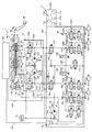
- FIG. 1 is a hydraulic circuit diagram of a brake system of a first embodiment.
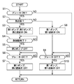
- 7 is a flowchart showing a flow of boost control in the boost control unit 41d of the first embodiment.
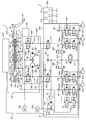
- FIG. 7 is a hydraulic circuit diagram of a brake system of a third embodiment.
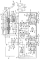
- FIG. 10 is a hydraulic circuit diagram of a brake system of a fourth embodiment.
- FIG. 1 is a perspective view of the brake device of the first embodiment.
- the brake system of the first embodiment is mounted on an electric vehicle having a motor generator such as a hybrid vehicle or an electric vehicle as a power source.
- a motor generator such as a hybrid vehicle or an electric vehicle as a power source.
- regenerative braking that brakes the vehicle can be performed by converting kinetic energy of the vehicle into electrical energy by a regenerative braking device that includes a motor generator.
- the brake device supplies brake fluid to a brake actuation unit provided in each wheel to generate a brake fluid pressure, thereby applying a braking force to each wheel.
- the brake device has a master cylinder unit 1, a hydraulic pressure control unit 2 and a second pump unit 3.
- Master cylinder unit 1 and hydraulic pressure control unit 2 are connected by primary piping (hydraulic pressure circuit) 4P, secondary piping (hydraulic pressure circuit) 4S, reservoir piping 4R1, and back pressure chamber piping 4B.
- the 2nd pump unit 3 is provided in the middle of primary piping 4P and secondary piping 4S.
- Master cylinder unit 1 and second pump unit 3 are connected by reservoir piping 4R2.
- Master cylinder unit 1 has a brake pedal BP (see FIG. 2), a reservoir RSV, a master cylinder M / C, and a stroke simulator SS (see FIG. 2).
- the brake pedal BP receives an input of a driver's brake operation.
- the reservoir RSV internally stores the brake fluid.
- the inside of the reservoir RSV is open to the atmosphere.
- Master cylinder M / C receives supply of brake fluid from reservoir RSV and is actuated by the driver's brake operation to generate fluid pressure.
- the stroke simulator SS generates a pedal reaction force and a pedal stroke by the inflow of the brake fluid according to the driver's brake operation.
- the fluid pressure control unit 2 has a plurality of solenoid valves, a first pump P1 (see FIG.
- the plurality of solenoid valves, the first pump P1 and the electronic control unit ECU are provided in a hydraulic pressure control unit housing (first housing) HG1.
- the plurality of solenoid valves are driven when generating the brake fluid pressure independently of the driver's brake operation.
- the first pump P1 pressurizes the brake fluid sucked from the reservoir RSV.
- the electronic control unit ECU controls the operation of a second pump P2 and a second shutoff valve 38, which will be described later, in addition to the plurality of solenoid valves and the first pump P1.
- the fluid pressure control unit 2 supplies the brake fluid to the brake actuation unit provided in each wheel via the wheel cylinder piping 4FL, 4FR, 4RL, 4RR.
- FIG. 2 is a hydraulic circuit diagram of the brake device of the first embodiment.
- Master cylinder unit 1 is not provided with an engine negative pressure booster that boosts the brake operation force using the intake negative pressure generated by the engine of the vehicle.
- the push rod PR is rotatably connected to the brake pedal BP.
- Master cylinder M / C is a tandem type master cylinder.
- the master cylinder M / C has a primary piston 5P and a free piston secondary piston 5S connected to the push rod PR as pistons that move in the axial direction according to the driver's brake operation.
- the primary piston 5P is provided with a stroke sensor 6 for detecting the stroke of the brake pedal BP.
- the brake actuation unit including the wheel cylinder W / C is a so-called disc type.
- the brake actuation unit has a brake disc and a caliper (hydraulic brake caliper).
- the brake disc is a brake rotor that rotates integrally with the tire.
- the caliper is disposed with a predetermined clearance with respect to the brake disk, and generates a braking force by moving by the wheel cylinder hydraulic pressure to contact the brake disk.
- the brake system has brake piping of two systems (primary P system and secondary S system).
- the brake piping system adopts, for example, an X piping system.
- subscripts P and S are added to the end of the respective reference numerals.
- the fluid pressure control unit 2 is provided between the master cylinder unit 1 and the wheel cylinder W / C.
- the fluid pressure control unit 2 individually controls the brake fluid supplied to each wheel cylinder W / C.
- the fluid pressure control unit 2 operates the wheel cylinder fluid pressure by the fluid pressure generated by at least one of the first pump P1 and the second pump P2 in a state where the communication between the master cylinder M / C and the wheel cylinder W / C is shut off. Control to increase pressure is possible.
- fluid pressure sensors 7, 8 and 9 are provided in the fluid pressure control unit housing HG1.
- the first pump P1 sucks in the brake fluid stored in the reservoir RSV through the reservoir pipe 4R1 by the rotational drive of the first motor M1 and discharges it toward the wheel cylinder W / C.
- the first pump P1 is a high pressure low flow type, for example, a gear pump.
- the first pump P1 is commonly used in the P system and the S system.
- the first pump P1 is driven by a first motor M1.
- the first motor M1 is, for example, a brushless motor, but may be a brushed motor.
- the master cylinder M / C is connected to the wheel cylinder W / C via the primary pipe 4P, the secondary pipe 4S and an oil passage (hydraulic circuit) 10 described later.
- Master cylinder M / C can increase the wheel cylinder hydraulic pressure of left front wheel FL and right rear wheel RR via oil path 10P of P system by the master cylinder hydraulic pressure generated in primary fluid chamber 11P.
- the master cylinder M / C can increase the wheel cylinder hydraulic pressure of the left rear wheel RL and the right front wheel FR through the oil passage 11S of the S system by the master cylinder hydraulic pressure generated in the secondary fluid chamber 11S.
- the primary piston 5P and the secondary piston 5S of the master cylinder M / C are axially movably inserted along the inner peripheral surface of the bottomed cylindrical cylinder 15.
- the cylinder 15 includes, in each system, a discharge port 12 connected to the fluid pressure control unit 2 and provided to be able to communicate with the wheel cylinder W / C, and a replenishment port 13 connected to and communicated with the reservoir RSV.
- a coil spring 14P is installed in the primary fluid chamber 11P in a compressed state.
- the coil spring 14S is set in the secondary fluid chamber 11S in a contracted and contracted state.
- the discharge port 12 is always open in both liquid chambers 11P and 11S.
- a stroke simulator oil passage 17 connected to the positive pressure chamber 16a of the stroke simulator SS is connected to the secondary fluid chamber 11S of the master cylinder M / C.
- the cylinder 15 has a back pressure chamber port 18 always open to the back pressure chamber 16 b of the stroke simulator SS.
- the back pressure chamber port 18 is connected to the back pressure chamber piping 4B. Between the positive pressure chamber 16a and the back pressure chamber 16b, the brake fluid can not move between each other.
- the stroke simulator SS has a spring 16c in the back pressure chamber 16b, and generates an operation reaction force on the brake pedal BP in accordance with the stroke of the piston 16d.
- Oil path 10P of P system connects primary piping 4P and wheel cylinders W / C of left front wheel FL and right rear wheel RR.
- the oil path 10S of the S system connects the secondary pipe 4S and the wheel cylinder W / C of the left rear wheel RL and the right front wheel FR.
- the oil passage 10 is provided with a normally open first shutoff valve 19.
- a normally open pressure increase valve 20 is provided corresponding to each wheel.
- the suction oil passage 21 connects a liquid reservoir 32 provided in the suction portion 24a of the first pump P1 and a pressure reduction oil passage 22 described later.
- the discharge oil passage (first discharge oil passage) 23 connects between the first shutoff valve 19 and the pressure increase valve 20 in the oil passage 10, and the discharge portion 24b of the first pump P1.
- the discharge oil passage (first discharge oil passage) 25P connects the downstream side of the discharge oil passage 23 and the oil passage 10P of the P system.
- the connection position 50P of the discharge oil passage 25P in the oil passage 10P is a connection position of the oil passage 10P with the discharge portion 24b of the first pump P1.
- the discharge oil passage 25P is provided with a normally closed primary communication valve 26P.
- the discharge oil passage (first discharge oil passage) 25S connects the downstream side of the discharge oil passage 23 and the oil passage 10S of the S system.
- the connection position 50S of the discharge oil passage 25S in the oil passage 10S is a connection position of the oil passage 10S with the discharge portion 24b of the first pump P1.
- the discharge oil passage 25S is provided with a normally closed secondary communication valve 26S.
- the first pressure reducing oil passage 27 connects the suction oil passage 21 between the discharge oil passage 25P and the discharge oil passage 25S.
- the first pressure reducing oil passage 27 is provided with a pressure regulating valve 28 that is normally open.
- the second pressure reducing oil passage 22 connects the wheel cylinder W / C side and the suction oil passage 21 with respect to the pressure increasing valve 20 in the oil passage 10.
- the pressure reducing oil passage 22 is provided with a normally closed pressure reducing valve 29.
- the second simulator oil passage 47 includes a stroke simulator in valve 30 and a stroke simulator out valve between the back pressure chamber piping 4B and the first shutoff valve 19S and the pressure increasing valves 20RL and 20FR in the oil passage 10S, and the suction oil passage 21. Connect via 31
- a liquid reservoir 32 is provided at a portion where the reservoir pipe 4R1 is connected to the suction oil passage 21 of the first pump P1.
- the discharge oil passages 25P and 25S constitute a communication passage connecting the P-system oil passage 10P and the S-system oil passage 10S.
- the first pump P1 is connected to the wheel cylinder W / C via the communication passage (discharge oil passages 25P, 25S) and the oil passages 10P, 10S.
- the first shutoff valve 19, the pressure increasing valve 20, the pressure regulating valve 28, and the pressure reducing valve 29 are proportional control valves in which the opening degree of the valve is adjusted according to the current supplied to the solenoid, It is an ON / OFF valve that is controlled to switch.
- the oil passage 10 is provided with a bypass oil passage 33 in parallel with the pressure increasing valve 20.
- the bypass oil passage 33 is provided with a check valve 34.
- the check valve 34 only allows the flow of brake fluid from the wheel cylinder W / C side to the master cylinder M / C side.
- a hydraulic pressure sensor 7 for detecting the hydraulic pressure at this point (the hydraulic pressure in the stroke simulator SS, the master cylinder pressure) is provided ing.
- a hydraulic pressure sensor 8 is provided between the first shutoff valve 19 and the pressure increasing valve 20 in the oil passage 10 for detecting the hydraulic pressure (foil cylinder hydraulic pressure) at this point.
- a hydraulic pressure sensor 9 for detecting the hydraulic pressure (pump discharge pressure) at this point is provided between the discharge oil passage 25 and the communication valve 26.
- the second pump unit 3 has a second pump P2.
- the second pump P2 is provided in a second pump housing (second housing) HG2.
- the second pump P2 is provided in each of the P system and the S system.
- the second pump P2 sucks the brake fluid stored in the reservoir RSV through the reservoir pipe 4R2 by the rotational drive of the second motor M2, and an oil path (hydraulic circuit) 37 formed in the second pump housing HG2 Discharge toward.
- the oil passage 37 is provided in the middle of the primary piping 4P and the secondary piping 4S.
- the second pump P2 is, for example, a gear pump of low pressure and high flow rate type.
- the second pump P2 has a larger specific discharge amount, which is a discharge amount per rotation, and a larger discharge amount per unit time than the first pump P1.
- the second pump P2 is driven by one second motor M2.
- the second motor M2 is, for example, a brushless motor, but may be a brushed motor.
- An intake oil passage 35 is provided in the second pump housing HG2.
- the suction oil passage 35 connects the reservoir pipe 4R2 and the suction portion 36a of the second pump P2.
- the oil passage 37 is provided with a normally open second shutoff valve 38.
- the second shutoff valve 38 is provided in the second pump housing HG2.
- the second shutoff valve 38 is a proportional control valve in which the opening degree of the valve is adjusted according to the current supplied to the solenoid.
- a discharge oil passage (second discharge oil passage) 39 is provided in the second pump housing HG2.
- the discharge oil passage 39 connects the oil passage 37 and the discharge portion 36b of the second pump P2.
- the connection position 51 of the discharge oil passage 39 in the oil passage 37 is a connection position of the oil passage 37 with the discharge portion 36 b of the second pump P2.
- the electronic control unit ECU receives the detection values of the stroke sensor 6 and the fluid pressure sensors 7, 8 and 9, and information on the traveling state (each wheel speed, lateral acceleration, etc.) sent from the vehicle side.
- the electronic control unit ECU controls the brake operation force of the driver by controlling the opening / closing operation of each solenoid valve of the hydraulic control unit 2 and the second pump unit 3 and the discharge amount of each pump based on the built-in program.
- the electronic control unit ECU and all the actuators (the first motor M1, the first shutoff valve 19, the pressure increasing valve 20, the communication valve 26, the pressure regulating valve 28, the pressure reducing valve 29, the second pump P2 and the second shutoff valve 38) is supplied with power from one battery 40.
- the battery 40 is a 14V battery.
- the brake system connecting both fluid chambers 11P and 11S of the master cylinder M / C and the wheel cylinder W / C when all the actuators are off (non-energized) as shown in FIG.
- the wheel cylinder fluid pressure is generated by the master cylinder fluid pressure generated using the pedal depression force, and the depression force brake (non-boost control) is realized.
- the first shutoff valve 19, the stroke simulator in valve 30 and the stroke simulator out valve 31 are turned ON, the first shutoff valve 19 is controlled in the valve closing direction, and the stroke simulator in valve 30 and the stroke simulator out
- the valve 31 is controlled in the valve opening direction, the volume of the brake system connecting the secondary fluid chamber 11S of the master cylinder M / C and the wheel cylinder W / C is reduced along with the movement of the piston 16d of the stroke simulator SS.
- the wheel hydraulic pressure is generated using the brake hydraulic pressure that has flowed out of the back pressure chamber 16b to realize the (second) depression force brake.
- the reservoir RSV and the wheel cylinder are controlled.
- the brake system intake oil passage 21, discharge oil passage 23, etc.
- W / C generates wheel cylinder hydraulic pressure by the hydraulic pressure generated using the first pump P1, and boost control, automatic brake control And a so-called brake-by-wire system capable of realizing regenerative coordinated control and the like.
- boost control automatic brake control
- a so-called brake-by-wire system capable of realizing regenerative coordinated control and the like.
- the second depression force brake it may be switched to the boost control or the automatic brake control.
- the brake system of the first embodiment includes the second pump unit 3 having the second pump P 2 and the second shutoff valve 38. Similar to the first pump P1, the second pump P2 sucks the brake fluid from the reservoir RSV, and discharges the pressurized brake fluid toward the primary pipe 4P and the secondary pipe 4S. That is, the second pump P2 is provided in parallel to the first pump P1 with respect to the hydraulic circuit (4P, 4S, 10P, 10S) connecting the master cylinder M / C and the wheel cylinder W / C. Further, the second shutoff valve 38 is provided between the first shutoff valve 19 and the master cylinder M / C. That is, the second shutoff valve 38 is provided in series with the first shutoff valve 19 on the hydraulic circuit.
- the second pump P2 and the second shutoff valve 38 can function as a standby redundant system of the first pump P1 and the first shutoff valve 19.
- the electronic control unit ECU controls the second shutoff valve 38 instead of the first shutoff valve 19 when the first shutoff valve 19 breaks down.
- the wheel cylinder hydraulic pressure can be increased by closing the second shutoff valve 38. Therefore, execution and continuation of boost control and automatic brake control are possible.
- the electronic control unit ECU can drive the second pump P2 to increase the wheel cylinder hydraulic pressure. In this case, the first shutoff valve 19 is turned off and the second shutoff valve 38 is turned on.
- the electronic control unit ECU includes a vehicle state detection unit 41a, a target wheel cylinder hydraulic pressure calculation unit 41b, a depression force brake control unit 41c, a boost control unit 41d, and a boost control switching unit 41e.
- the vehicle state detection unit 41a detects ON / OFF of the brake from the detection value of the stroke sensor 6, and also detects a sudden braking state.
- the vehicle state detection unit 41 a detects the target wheel cylinder hydraulic pressure calculated by the target wheel cylinder hydraulic pressure calculation unit 41 b and the previous value of the target wheel cylinder hydraulic pressure when the change speed of the brake pedal stroke exceeds a predetermined speed threshold. If the deviation of V exceeds the predetermined deviation threshold value, it is determined that the braking state is sudden.
- the target wheel cylinder hydraulic pressure calculation unit 41b calculates a target wheel cylinder hydraulic pressure. Specifically, based on the stroke of the brake pedal BP, an ideal relationship characteristic between the predetermined boost ratio, that is, the pedal stroke and the driver's requested brake fluid pressure (vehicle deceleration requested by the driver) is realized. Calculate the target wheel cylinder hydraulic pressure. At the time of regenerative coordinated brake control, the target wheel cylinder hydraulic pressure is calculated by subtracting the hydraulic pressure conversion value of the execution regenerative braking force from the driver's requested brake hydraulic pressure. In automatic brake control, a target wheel cylinder hydraulic pressure of each wheel capable of achieving a desired vehicle motion state is calculated based on the detected traveling state of the vehicle and the surrounding state.
- the treading force brake control unit 41c does not function the stroke simulator SS by controlling the first shutoff valve 19 in the valve opening direction, the stroke simulator in valve 30 in the valve closing direction, and the stroke simulator out valve 31 in the valve closing direction.
- the present invention realizes a depression brake that generates wheel cylinder fluid pressure by master cylinder fluid pressure.
- the boost control unit 41d makes the state of the fluid pressure control unit 2 a state in which the wheel cylinder fluid pressure can be generated by the first pump P1, and boost control is performed. Run.
- the boost control unit 41 d controls each actuator to realize a target wheel cylinder hydraulic pressure.
- the electronic control unit ECU controls the stroke simulator in valve 30 in the valve closing direction, and controls the stroke simulator out valve 31 in the valve opening direction to cause the stroke simulator SS to function.
- the boost control switching unit 41 e switches the depression force brake and the boost control by controlling the operation of the master cylinder M / C based on the calculated target wheel cylinder hydraulic pressure.
- the wheel cylinder is generated by the depression force generation unit 41c. Generate hydraulic pressure.
- the boost control unit 41d generates a wheel cylinder hydraulic pressure.
- the boost control switching unit 41e generates the wheel cylinder hydraulic pressure by the second depression force brake, and thereafter, the wheel by the boost control unit 41d. It is also possible to switch to generate cylinder fluid pressure.
- FIG. 3 is a flow chart showing the flow of boost control in the boost control unit 41d of the first embodiment.
- step S1 it is determined whether or not the brake ON is detected in the vehicle state detection unit 41a. In the case of YES, the process proceeds to step S2, and in the case of NO, the process proceeds to return.
- step S2 it is determined whether a sudden braking state is detected in the vehicle state detection unit 41a.
- step S3 the process proceeds to step S3, and in the case of NO, the process proceeds to step S8.
- step S4 the first pump P1, the second pump P2 and the second shutoff valve 38 are turned on.
- step S4 it is determined whether the end of the sudden braking state has been detected in the vehicle state detection unit 41a. In the case of YES, the process proceeds to step S5, and in the case of NO, step S4 is repeated.
- step S5 the second pump P2 is turned off.
- step S6 it is determined whether or not the brake off has been detected in the vehicle state detection unit 41a. In the case of YES, the process proceeds to step S7, and in the case of NO, step S6 is repeated.
- step S7 the first pump P1 and the second shutoff valve 38 are turned off.
- step S8 the first pump P1 and the first shutoff valve 19 are turned on.
- step S9 it is determined whether or not the brake OFF has been detected in the vehicle state detection unit 41a. In the case of YES, the process proceeds to step S10, and in the case of NO, step S9 is repeated.
- step S10 the first pump P1 and the first shutoff valve 19 are turned off.
- the boost control unit 41 d controls the first shutoff valve 19 in the valve closing direction and drives only the first pump P ⁇ b> 1 during non-sustained braking.
- the boost control unit 41d controls the second shutoff valve 38 in the valve closing direction at the time of sudden braking to drive the first pump P1 and the second pump P2 together, and then, when the non-quick braking state is achieved, the second The pump P2 is stopped and only the first pump P1 is driven.
- the braking force occurs in earnest after the clearance between the brake disc and the brake pad is clogged
- the amount of liquid consumed is large. That is, in the low pressure region until the clearance is clogged, the gradient in which the hydraulic pressure increases with the increase in the liquid amount is small as compared with the high pressure region after the clearance is clogged. That is, since the amount of fluid consumed to generate the fluid pressure in the low pressure region is larger than that in the high pressure region, the fluid pressure does not easily increase even if the same fluid amount is supplied.
- the clearance can be quickly packed in the low pressure region where the amount of liquid consumed is large, the pressure increase response of the wheel cylinder can be effectively improved.
- the clearance tends to be set relatively large in order to suppress the deterioration of the fuel efficiency caused by the friction between the brake disc and the brake pad. Therefore, in the electric vehicle, if the clearance can be quickly packed, the pressure increase response can be significantly improved. The same applies to a drum-type brake operating unit.
- the wheel cylinder W / C is pressurized only with the first pump P1 in the normal use area (during non-sudden braking), while it is added to the first pump P1 during the sudden braking.
- the pump P2 is operated to increase the wheel cylinder pressure. Since high responsiveness is not necessary at the time of non-sudden braking, the necessary braking force can be secured only by the discharge amount of the high-pressure low-flow type first pump P1.
- the second pump P2 of low pressure and high flow rate type the clearance can be quickly packed in the low pressure region where the amount of liquid consumption is large, and pressure increase response can be improved. .
- the second pump P2 does not correspond to the high pressure region, the consumption flow rate in the high pressure region is small, so that the necessary responsiveness can be secured with only the first pump P1. Also, even if automatic brake control is performed to always operate the pump such as following vehicle and automatic operation, the second pump P2 operates only at the time of sudden braking, so only the first pump P1 It will always operate. Since the first pump P1 is a high-pressure low-flow type pump, problems such as the consumption of the battery 40 and the cost increase of the power supply harness do not occur. That is, the brake device of the first embodiment can secure the pressure increase response of the wheel cylinder W / C at the time of sudden braking while suppressing the consumption of the battery and the cost increase of the harness.
- a desired brake hydraulic pressure can be obtained by closing the second shutoff valve 38 and driving the first pump P1.
- the brake device according to (1) further including a second pump P2 provided in the hydraulic circuit and supplying brake fluid in parallel with the first pump P1 to the wheel cylinder W / C;
- the shutoff valve 38 is provided between the connection position 51 with the discharge portion 36b of the second pump P2 in the hydraulic pressure circuit and the master cylinder M / C. Therefore, even when the first shutoff valve 19 has an open failure, a desired brake hydraulic pressure can be obtained by closing the second shutoff valve 38 and driving at least one of the first pump P1 and the second pump P2.
- the second shutoff valve 38 is controlled in the valve closing direction when at least the second pump P2 is actuated. Therefore, by controlling the second shutoff valve 38 in the valve closing direction, it is possible to prevent the brake fluid discharged from the second pump P2 from flowing to the master cylinder M / C side, so the wheel cylinder hydraulic pressure can be increased. .
- the first pump P1 and the second pump P2 are detected according to the detection result of the vehicle state detection unit 41a that detects the vehicle state (sudden braking, non-sudden braking).
- the electronic control unit ECU that controls the first shutoff valve 19 and / or the second shutoff valve 38. Therefore, each pump P1 and P2 and each cutoff valve 19 and 38 can be arbitrarily controlled according to a vehicle state.
- the second pump P2 has a larger specific discharge amount than the first pump P1. Therefore, the pressure increase responsiveness of the wheel cylinder W / C can be obtained by supplying the brake fluid by the second pump P2.
- the second pump P2 has a larger discharge amount per unit time than the first pump P1. Therefore, the pressure increase responsiveness of the wheel cylinder W / C can be obtained by supplying the brake fluid by the second pump P2.
- the electronic control unit ECU controls the second shutoff valve 38 in the valve closing direction when the vehicle state detection unit 41a detects sudden braking, and the first pump Drive both P1 and the second pump P2. Therefore, the pressure increase response of the wheel cylinder W / C at the time of sudden braking is enhanced, and the necessary braking force can be obtained more reliably.
- a first discharge oil passage (discharge oil passage 23, discharge oil passage 25) connecting the discharge portion 24b of the first pump P1 and the hydraulic circuit;
- a second discharge oil passage 39 connecting between the connection position 50 at which the first discharge oil passage is connected to the hydraulic pressure circuit and the master cylinder M / C, and the discharge portion 36b of the second pump P2 is provided.
- the first shutoff valve 19 has a connection position 50 with the discharge portion 24b of the first pump P1 and a discharge portion 36b of the second pump P2.
- the electronic control unit ECU is provided between the connection position 51 and the electronic control unit ECU controls at least one of the first shutoff valve 19 and the second shutoff valve 38 in the valve closing direction when sudden braking is not detected by the vehicle state detection unit 41a.
- the first pump P1 is driven and the second pump P2 is not driven. Therefore, power consumption can be suppressed by driving only the first pump P1 at the time of non-sustained braking, which does not require high responsiveness.
- the first pump P1 and the first shutoff valve 19 are provided in the hydraulic pressure control unit housing HG1, and the second pump P2 and the second shutoff valve 38 are hydraulically operated. It is provided in a second pump housing HG2 provided separately from the control unit housing HG1. Therefore, since the individual housings can be arranged small and separated, the degree of freedom of mounting on the vehicle can be expanded as compared with the case where both the pumps P1 and P2 and the shutoff valves 19 and 38 are provided in one housing.
- the second pump P2 for supplying the brake fluid to the wheel cylinder W / C through the two discharge oil passages 39 and the second discharge oil passage 39, and the connection position 50 of the first discharge oil passage of the hydraulic circuit and the second Provided between the first shutoff valve 19 provided between the discharge oil passage 39 and the connection position 51, and between the second discharge oil passage 39 of the hydraulic circuit and the master cylinder M / C
- the second shut-off valve 38 and the electronic control unit ECU that controls the shut-off valves 19 and 38 in accordance with the operating states of the pumps P1 and P2 are provided. Therefore, even when the first shutoff valve 19 has an open failure, a desired brake hydraulic pressure can be obtained by closing the second shutoff valve 38 and driving at least one of the first pump P1 and the second pump P2. Be Further, even when the first pump P1 fails, a desired brake fluid pressure can be obtained by driving the second pump P2.
- the second pump P2 which supplies the brake fluid to the wheel cylinder W / C via the 2 discharge oil passage 39 and the second discharge oil passage 39 and has a specific discharge amount larger than that of the first pump P1, and A first shutoff valve 19 provided between the connection position 50 of the first discharge oil passage and the connection position 51 of the second discharge oil passage 39, and a second discharge oil passage 39 of the hydraulic circuit.
- a second shut-off valve 38 which is provided between the connection position 51 and the master cylinder M / C, and the electronic control unit ECU for selectively controlling the respective shut-off valves 19,38, a. Therefore, even when the first shutoff valve 19 has an open failure, the desired brake fluid pressure can be obtained by closing the second shutoff valve 38 and driving one of the first pump P1 and the second pump P2. . Further, even when the first pump P1 fails, a desired brake fluid pressure can be obtained by driving the second pump P2. Furthermore, power consumption can be suppressed by selectively using the first shutoff valve 19 and the second shutoff valve 38.
- Example 2 Next, Example 2 will be described. Since the basic configuration is the same as that of the first embodiment, only different points will be described.
- the electronic control unit (control unit) ECU according to the second embodiment is configured to control the first pump P1 and the second pump P2, the first shutoff valve 19 and the second pump P2 according to the vehicle type during boost control, automatic brake control and regenerative coordination control. 2) control the shutoff valve 38; Specifically, the boost control unit 41d of the electronic control unit ECU controls the first shutoff valve 19 in the valve closing direction when the vehicle size is equal to or less than the preset vehicle model, and the first pump P1 Drive.
- the boost control unit 41d controls the second shutoff valve 38 in the valve closing direction to drive the first pump P1 and the second pump P2.
- the total length of the vehicle, the wheel base, the displacement, etc. can be used as the parameters of the vehicle specifications representing the vehicle design.
- the electronic control unit ECU controls the first pump P1 and the second pump P2 and the first shutoff valve 19 and the second shutoff valve 38 according to the vehicle size. Equipped. Therefore, the first pump P1, the second pump P2, the first shutoff valve 19, and the second shutoff valve 38 can be arbitrarily controlled according to the vehicle specifications.
- the electronic control unit ECU controls the second shutoff valve 38 in the valve closing direction when the vehicle size is larger than the preset vehicle size, and the first pump Drive both P1 and the second pump P2. Therefore, when the vehicle size is large, the necessary braking force can be obtained more reliably by driving the first pump P1 and the second pump P2.
- FIG. 4 is a hydraulic circuit diagram of the brake device of the third embodiment.
- the brake system of the third embodiment includes two batteries 40a and 40b.
- the first battery (first power supply) 40a supplies electric power to the actuators (the first motor M1, the first shutoff valve 19, the pressure increasing valve 20, the communication valve 26, the pressure regulating valve 28, and the pressure reducing valve 29) of the hydraulic pressure control unit 2.
- the second battery (second power supply) 40 b supplies power to each actuator (second pump P 2 and second shutoff valve 38) of the second pump unit 3.
- the batteries 40a and 40b are both 14V batteries.
- the second pump unit 3 also has an electronic control unit 42.
- the electronic control unit 42 receives the supply of power from the second battery 40b.
- the electronic control unit ECU fails and the first pump P1 and the first shutoff valve 19 become uncontrollable
- the electronic control unit 42 controls the second pump P2 and the second shutoff valve 38 so that the wheel cylinder is operated. Increase the fluid pressure.
- the brake device according to (2) above includes the first battery 40 a that supplies power to the first shutoff valve 19 and the second battery 40 b that supplies power to the second shutoff valve 38. Therefore, even if one battery fails, the wheel cylinder hydraulic pressure can be increased by controlling the pump and the shutoff valve that receive power supply from the other normal battery.
- FIG. 5 is a hydraulic circuit diagram of the brake device of the fourth embodiment.
- the second shutoff valve 38 is provided in the hydraulic pressure control unit 2.
- the second shutoff valve 38 is disposed closer to the master cylinder M / C than the first shutoff valve 19 in the oil passage 10.
- the discharge portion 36 b of the second pump P 2 is connected to the discharge oil passage 23 via the discharge oil passage 43, the pipe 44, and the discharge oil passage 45. That is, in the fourth embodiment, the connection position 50 of the oil passage 10 with the discharge portion 24b of the first pump P1 matches the connection position 51 of the discharge portion 36b of the second pump P2.
- the discharge oil passage 43 is formed in the second pump housing HG2, and the discharge oil passage 45 is formed in the fluid pressure control unit housing HG1.
- the pipe 44 connects the discharge oil passage 43 and the discharge oil passage 45.
- the first pump P1 is a plunger pump having five plungers excellent in sound vibration performance and the like.
- the stroke simulator SS of the fourth embodiment includes a piston 46a, a first spring 46b, a retainer member 46c, a second spring 46d, and a damper 46e.
- the piston 46a is provided so that the inside of the stroke simulator SS is separated into two chambers (a positive pressure chamber 16a and a back pressure chamber 16b) so as to be axially movable in the chambers.
- the first spring 46b biases the piston 46a toward the positive pressure chamber 16a (in the direction to reduce the volume of the positive pressure chamber 16a and enlarge the volume of the back pressure chamber 16b).
- the retainer member 46c holds the first spring 46b.
- the second spring 46d always biases the retainer member 46c toward the positive pressure chamber 16a.
- the biasing force of the second spring 46 d is larger than the biasing force of the first spring 46 b.
- the damper 46e is a cushioning material for generating a bottomed feeling of the pedal.
- the second shutoff valve 38 is controlled in the valve closing direction to operate at least one of the first pump P1 and the second pump P2. Thus, the desired brake fluid pressure can be obtained.
- Example 5 will now be described. Since the basic configuration is the same as that of the first embodiment, only different points will be described.
- the electronic control unit ECU (control unit) of the fifth embodiment boosts the wheel cylinder W / C with only the second pump P2 in the low pressure region at the time of sudden braking, and operates the wheel cylinder with only the first pump P1 in the high pressure region Increase W / C pressure. Therefore, in the fifth embodiment, power consumption can be suppressed by selectively using the first pump P1 and the second pump P2.
- the said control unit controls each said pump and each said shut-off valve according to the detection result of the vehicle state detection part which detects a vehicle state. Therefore, each pump and each shutoff valve can be arbitrarily controlled according to the vehicle state.
- the second pump has a specific discharge amount larger than that of the first pump. Therefore, the pressure increase response of the wheel cylinder can be obtained by supplying the brake fluid by the second pump.
- the control unit controls the second shutoff valve in the valve closing direction and drives both the first pump and the second pump when sudden braking is detected by the vehicle state detection unit.
Landscapes
- Engineering & Computer Science (AREA)
- Transportation (AREA)
- Mechanical Engineering (AREA)
- Physics & Mathematics (AREA)
- Fluid Mechanics (AREA)
- Electromagnetism (AREA)
- Regulating Braking Force (AREA)
- Braking Systems And Boosters (AREA)
- Valves And Accessory Devices For Braking Systems (AREA)
Abstract
Description
本発明の目的は、遮断弁の開故障時に所望のブレーキ液圧が得られるブレーキ装置を提供することにある。
図1は、実施例1のブレーキ装置の斜視図である。
実施例1のブレーキ装置は、ハイブリッド車や電気自動車等のモータジェネレータを動力源とする電動車両に搭載されている。電動車両においては、モータジェネレータを含む回生制動装置により、車両の運動エネルギーを電気エネルギーに変換することで車両を制動する回生制動を実行可能である。ブレーキ装置は、各輪に設けられたブレーキ作動ユニットにブレーキ液を供給し、ブレーキ液圧を発生させることで、各輪に制動力を付与する。ブレーキ装置は、マスタシリンダユニット1、液圧制御ユニット2および第2ポンプユニット3を有する。マスタシリンダユニット1および液圧制御ユニット2は、プライマリ配管(液圧回路)4P、セカンダリ配管(液圧回路)4S、リザーバ配管4R1および背圧室配管4Bにより接続されている。第2ポンプユニット3は、プライマリ配管4Pおよびセカンダリ配管4Sの途中に設けられている。マスタシリンダユニット1と第2ポンプユニット3は、リザーバ配管4R2により接続されている。
マスタシリンダユニット1は、車両のエンジンが発生する吸気負圧を利用してブレーキ操作力を倍力するエンジン負圧ブースタを備えていない。プッシュロッドPRは、ブレーキペダルBPに回動自在に接続されている。マスタシリンダM/Cは、タンデム型のマスタシリンダである。マスタシリンダM/Cは、運転者のブレーキ操作に応じて軸方向移動するピストンとして、プッシュロッドPRに接続されるプライマリピストン5Pおよびフリーピストン型のセカンダリピストン5Sを有する。プライマリピストン5Pには、ブレーキペダルBPのストロークを検出するストロークセンサ6が設けられている。
ホイルシリンダW/Cを含むブレーキ作動ユニットはいわゆるディスク式である。ブレーキ作動ユニットは、ブレーキディスクおよびキャリパ(油圧式ブレーキキャリパ)を有する。ブレーキディスクは、タイヤと一体に回転するブレーキロータである。キャリパは、ブレーキディスクに対し所定クリアランスをもって配置され、ホイルシリンダ液圧によって移動してブレーキディスクに接触することで制動力を発生する。ブレーキ装置は2系統(プライマリP系統およびセカンダリS系統)のブレーキ配管を有する。ブレーキ配管形式は、例えばX配管形式を採用している。なお、前後配管等、他の配管形式を採用してもよい。以下、P系統に対応して設けられた部材とS系統に対応する部材とを区別する場合は、それぞれの符号の末尾に添字P,Sを付す。
第1ポンプP1は、第1モータM1の回転駆動によりリザーバ配管4R1を介してリザーバRSV内に貯留されたブレーキ液を吸入し、ホイルシリンダW/Cに向けて吐出する。第1ポンプP1は、高圧低流量型の、例えばギアポンプである。第1ポンプP1は、P系統およびS系統で共通に用いられる。第1ポンプP1は、第1モータM1で駆動される。第1モータM1は、例えばブラシレスモータであるが、ブラシ付きモータでもよい。
P系統の油路10Pは、プライマリ配管4Pと左前輪FLおよび右後輪RRのホイルシリンダW/Cとを接続する。S系統の油路10Sは、セカンダリ配管4Sと左後輪RLおよび右前輪FRのホイルシリンダW/Cとを接続する。油路10には、常開の第1遮断弁19が設けられている。油路10における第1遮断弁19よりもホイルシリンダW/C側には、各輪に対応して常開の増圧弁20が設けられている。吸入油路21は、第1ポンプP1の吸入部24aに設けられた液溜まり32と後述する減圧油路22とを接続する。吐出油路(第1吐出油路)23は、油路10における第1遮断弁19と増圧弁20との間と、第1ポンプP1の吐出部24bとを接続する。吐出油路(第1吐出油路)25Pは、吐出油路23の下流側とP系統の油路10Pとを接続する。油路10Pにおける吐出油路25Pの接続位置50Pは、油路10Pにおける第1ポンプP1の吐出部24bとの接続位置である。吐出油路25Pには、常閉のプライマリ連通弁26Pが設けられている。吐出油路(第1吐出油路)25Sは、吐出油路23の下流側とS系統の油路10Sとを接続する。油路10Sにおける吐出油路25Sの接続位置50Sは、油路10Sにおける第1ポンプP1の吐出部24bとの接続位置である。吐出油路25Sには、常閉のセカンダリ連通弁26Sが設けられている。第1減圧油路27は、吐出油路25Pと吐出油路25Sとの間と吸入油路21とを接続する。第1減圧油路27には、常開の調圧弁28が設けられている。第2減圧油路22は、油路10における増圧弁20よりもホイルシリンダW/C側と吸入油路21とを接続する。減圧油路22には、常閉の減圧弁29が設けられている。第2シミュレータ油路47は、背圧室配管4Bと油路10Sにおける第1遮断弁19Sと増圧弁20RL,20FRとの間、および吸入油路21とをストロークシミュレータイン弁30およびストロークシミュレータアウト弁31を介して接続する。
油路10には、増圧弁20と並列にバイパス油路33が設けられている。バイパス油路33には、チェック弁34が設けられている。チェック弁34は、ホイルシリンダW/C側からマスタシリンダM/C側へのブレーキ液の流れのみを許容する。油路10の第1遮断弁19よりもマスタシリンダM/C側には、この箇所の液圧(ストロークシミュレータSS内の液圧であり、マスタシリンダ圧)を検出する液圧センサ7が設けられている。油路10における第1遮断弁19と増圧弁20との間には、この箇所の液圧(ホイルシリンダ液圧)を検出する液圧センサ8が設けられている。吐出油路25と連通弁26との間には、この箇所の液圧(ポンプ吐出圧)を検出する液圧センサ9が設けられている。
車両状態検出部41aは、ストロークセンサ6の検出値からブレーキのON/OFFを検出すると共に、急制動状態を検出する。車両状態検出部41aは、ブレーキペダルストロークの変化速度が所定の速度閾値を超える場合や、目標ホイルシリンダ液圧算出部41bにより算出された目標ホイルシリンダ液圧と目標ホイルシリンダ液圧の前回値との偏差が所定の偏差閾値を超える場合に、急制動状態と判定する。
目標ホイルシリンダ液圧算出部41bは、目標ホイルシリンダ液圧を算出する。具体的には、ブレーキペダルBPのストロークに基づき、所定の倍力比、すなわちペダルストロークと運転者の要求ブレーキ液圧(運転者が要求する車両減速度)との間の理想の関係特性を実現する目標ホイルシリンダ液圧を算出する。回生協調ブレーキ制御時には、運転者の要求ブレーキ液圧から実行回生制動力の液圧換算値を減じて目標ホイルシリンダ液圧を算出する。自動ブレーキ制御では、検出された車両の走行状態や周囲の状態に基づき、所望の車両運動状態を実現可能な各輪の目標ホイルシリンダ液圧を算出する。
踏力ブレーキ制御部41cは、第1遮断弁19を開弁方向に、ストロークシミュレータイン弁30を閉弁方向に、ストロークシミュレータアウト弁31を閉弁方向に制御することで、ストロークシミュレータSSが機能しないように構成し、マスタシリンダ液圧によりホイルシリンダ液圧を発生させる踏力ブレーキを実現する。
倍力制御切り替え部41eは、算出された目標ホイルシリンダ液圧に基づき、マスタシリンダM/Cの作動を制御して、踏力ブレーキと倍力制御とを切り替える。具体的には、車両状態検出部41aによりブレーキ操作の開始が検出されると、算出された目標ホイルシリンダ液圧が踏力ブレーキのみで達成可能である場合には、踏力ブレーキ発生部41cによりホイルシリンダ液圧を発生させる。一方、ブレーキ踏み込み操作時に算出された目標ホイルシリンダ液圧が踏力ブレーキのみで達成不能な場合には、倍力制御部41dによりホイルシリンダ液圧を発生させる。また、倍力制御切り替え部41eは、車両状態検出部41aにより急制動状態が検出された場合には、第2の踏力ブレーキによりホイルシリンダ液圧を発生させ、その後、倍力制御部41dによりホイルシリンダ液圧を発生させるよう切り替えることもできる。
図3は、実施例1の倍力制御部41dにおける倍力制御の流れを示すフローチャートである。
ステップS1では、車両状態検出部41aにおいてブレーキONが検出されたかを判定する。YESの場合はステップS2へ進み、NOの場合はリターンへ進む。
ステップS2では、車両状態検出部41aにおいて急制動状態が検出されたかを判定する。YESの場合はステップS3へ進み、NOの場合はステップS8へ進む。
ステップS3では、第1ポンプP1、第2ポンプP2および第2遮断弁38をONする。
ステップS4では、車両状態検出部41aにおいて急制動状態の終了が検出されたかを判定する。YESの場合はステップS5へ進み、NOの場合はステップS4を繰り返す。
ステップS5では、第2ポンプP2をOFFする。
ステップS6では、車両状態検出部41aにおいてブレーキOFFが検出されたかを判定する。YESの場合はステップS7へ進み、NOの場合はステップS6を繰り返す。
ステップS7では、第1ポンプP1および第2遮断弁38をOFFする。
ステップS8では、第1ポンプP1および第1遮断弁19をONする。
ステップS9では、車両状態検出部41aにおいてブレーキOFFが検出されたかを判定する。YESの場合はステップS10へ進み、NOの場合はステップS9を繰り返す。
ステップS10では、第1ポンプP1および第1遮断弁19をOFFする。
以上のように、倍力制御部41dは、非急制動時には第1遮断弁19を閉弁方向に制御して第1ポンプP1のみを駆動する。一方、倍力制御部41dは、急制動時には第2遮断弁38を閉弁方向に制御して第1ポンプP1および第2ポンプP2を共に駆動し、その後、非急制動状態となったら第2ポンプP2を停止して第1ポンプP1のみを駆動する。
ディスク式のブレーキ作動ユニットにおいて、ホイルシリンダの液圧と液量との関係を見ると、ブレーキ液の供給開始後、ブレーキディスクとブレーキパッドとのクリアランスが詰まった後に制動力が本格的に発生するに至るまでの領域で、消費液量が多い。すなわち、クリアランスが詰まるまでの低圧領域では、クリアランスが詰まった後の高圧領域と比較して、液量の増大に対して液圧が増大する勾配が小さい。つまり、低圧領域では液圧を発生させるために消費する液量が高圧領域と比べて多いため、同じ液量を供給してもなかなか液圧が増大しない。換言すると、消費液量が多い低圧領域でクリアランスを素早く詰めることができれば、ホイルシリンダの増圧応答性を効果的に向上できる。特に、回生制動を実行する電動車両においては、ブレーキディスクとブレーキパッドとの摩擦に伴う燃費の悪化を抑制するために、クリアランスが比較的大きく設定される傾向にある。よって、電動車両では、クリアランスを素早く詰めることができれば、増圧応答性を顕著に向上できる。なお、ドラム式のブレーキ作動ユニットについても同様である。
(1) 運転者のブレーキ操作に応じてブレーキ液を加圧するマスタシリンダM/Cとブレーキ液圧に応じて車輪FL,FR,RL,RRに制動力を付与するホイルシリンダW/Cとを接続する液圧回路(プライマリ配管4P,セカンダリ配管4S,油路10,油路37)と、液圧回路にブレーキ液を供給する第1ポンプP1と、液圧回路における第1ポンプP1の吐出部24bとの接続位置50とマスタシリンダM/Cとの間に設けられた第1遮断弁19と、第1遮断弁19とマスタシリンダM/Cとの間に設けられた第2遮断弁38と、を備えた。
よって、第1遮断弁19が開故障した場合であっても、第2遮断弁38を閉じて第1ポンプP1を駆動することにより、所望のブレーキ液圧が得られる。
(2) 上記(1)に記載のブレーキ装置において、液圧回路に設けられ、ホイルシリンダW/Cに対して第1ポンプP1と並列にブレーキ液を供給する第2ポンプP2を備え、第2遮断弁38は、液圧回路における第2ポンプP2の吐出部36bとの接続位置51とマスタシリンダM/Cとの間に設けられている。
よって、第1遮断弁19が開故障した場合であっても、第2遮断弁38を閉じて第1ポンプP1と第2ポンプP2の少なくとも一方を駆動することにより、所望のブレーキ液圧が得られる。また、第1ポンプP1が故障した場合であっても、第2ポンプP2を駆動することにより、所望のブレーキ液圧が得られる。
(3) 上記(2)に記載のブレーキ装置において、第2遮断弁38は、少なくとも第2ポンプP2が作動すると閉弁方向に制御される。
よって、第2遮断弁38を閉弁方向に制御することにより、第2ポンプP2から吐出されたブレーキ液がマスタシリンダM/C側に流れるのを阻止できるため、ホイルシリンダ液圧を増圧できる。
よって、車両状態に応じて各ポンプP1,P2および各遮断弁19,38を任意に制御できる。
(5) 上記(4)に記載のブレーキ装置において、第2ポンプP2は、第1ポンプP1よりも固有吐出量が多い。
よって、第2ポンプP2でブレーキ液を供給することでホイルシリンダW/Cの増圧応答性が稼げる。
(6) 上記(4)に記載のブレーキ装置において、第2ポンプP2は、第1ポンプP1よりも単位時間当たりの吐出量が多い。
よって、第2ポンプP2でブレーキ液を供給することでホイルシリンダW/Cの増圧応答性が稼げる。
(7) 上記(4)に記載のブレーキ装置において、電子制御ユニットECUは、車両状態検出部41aにより急制動が検出されると、第2遮断弁38を閉弁方向に制御し、第1ポンプP1と第2ポンプP2の両方を駆動する。
よって、急制動時におけるホイルシリンダW/Cの増圧応答性が高められ、必要な制動力がより確実に得られる。
よって、油路を簡素化できる。
(9) 上記(2)に記載のブレーキ装置において、第1遮断弁19は、液圧回路において、第1ポンプP1の吐出部24bとの接続位置50と第2ポンプP2の吐出部36bとの接続位置51との間に設けられ、電子制御ユニットECUは、車両状態検出部41aにより急制動が検出されない場合は、第1遮断弁19または第2遮断弁38の少なくとも一方を閉弁方向に制御し、第1ポンプP1を駆動し、第2ポンプP2を非駆動とする。
よって、高応答性が不要な非急制動時には第1ポンプP1のみを駆動することで消費電力を抑制できる。
(10) 上記(2)に記載のブレーキ装置において、第1ポンプP1と第1遮断弁19は、液圧制御ユニットハウジングHG1に設けられ、第2ポンプP2と第2遮断弁38は、液圧制御ユニットハウジングHG1とは別に設けられた第2ポンプハウジングHG2に設けられている。
よって、個々のハウジングを小さく、かつ、離して配置できるため、両ポンプP1,P2および両遮断弁19,38を1つのハウジングに設けた場合と比べて、車両搭載性の自由度を拡大できる。
よって、第1遮断弁19が開故障した場合であっても、第2遮断弁38を閉じて第1ポンプP1と第2ポンプP2の少なくとも一方を駆動することにより、所望のブレーキ液圧が得られる。また、第1ポンプP1が故障した場合であっても、第2ポンプP2を駆動することにより、所望のブレーキ液圧が得られる。
よって、第1遮断弁19が開故障した場合であっても、第2遮断弁38を閉じて第1ポンプP1と第2ポンプP2の一方を駆動することにより、所望のブレーキ液圧が得られる。また、第1ポンプP1が故障した場合であっても、第2ポンプP2を駆動することにより、所望のブレーキ液圧が得られる。さらに、第1遮断弁19と第2遮断弁38とを選択的に使うことで消費電力を抑制できる。
次に、実施例2について説明する。基本的な構成は実施例1と同じであるため、異なる点についてのみ説明する。実施例2の電子制御ユニット(コントロールユニット)ECUは、倍力制御、自動ブレーキ制御や回生協調制御に際し、車格に応じて第1ポンプP1および第2ポンプP2と、第1遮断弁19および第2遮断弁38とを制御する。具体的には、電子制御ユニットECUの倍力制御部41dは、車格があらかじめ設定された車格以下である場合には、第1遮断弁19を閉弁方向に制御し、第1ポンプP1を駆動する。一方、倍力制御部41dは、車格があらかじめ設定された車格よりも大きい場合には、第2遮断弁38を閉弁方向に制御し、第1ポンプP1および第2ポンプP2を駆動する。ここで、車格を表す車両諸元のパラメータは、例えば、車両の全長、ホイルベース、排気量等を用いることができる。
(13) 上記(2)に記載のブレーキ装置において、車格に応じて、第1ポンプP1および第2ポンプP2と、第1遮断弁19および第2遮断弁38とを制御する電子制御ユニットECUを備えた。
よって、車両諸元に応じて第1ポンプP1、第2ポンプP2、第1遮断弁19および第2遮断弁38を任意に制御できる。
(14) 上記(13)に記載のブレーキ装置において、電子制御ユニットECUは、車格があらかじめ設定された車格よりも大きい場合、第2遮断弁38を閉弁方向に制御し、第1ポンプP1と第2ポンプP2の両方を駆動する。
よって、車格が大きい場合には第1ポンプP1および第2ポンプP2を駆動することにより、必要な制動力がより確実に得られる。
次に、実施例3について説明する。基本的な構成は実施例1と同じであるため、異なる点についてのみ説明する。図4は、実施例3のブレーキ装置の油圧回路図である。
実施例3のブレーキ装置は、2つのバッテリ40a,40bを備える。第1バッテリ(第1電源)40aは、液圧制御ユニット2の各アクチュエータ(第1モータM1、第1遮断弁19、増圧弁20、連通弁26、調圧弁28、減圧弁29)に電力を供給する。第2バッテリ(第2電源)40bは、第2ポンプユニット3の各アクチュエータ(第2ポンプP2および第2遮断弁38)に電力を供給する。バッテリ40a,40bは、いずれも14Vバッテリである。また、第2ポンプユニット3は、電子制御ユニット42を有する。電子制御ユニット42は第2バッテリ40bから電力の供給を受ける。電子制御ユニット42は、電子制御ユニットECUが失陥して第1ポンプP1および第1遮断弁19が制御不能となった場合、第2ポンプP2および第2遮断弁38を制御することでホイルシリンダ液圧を増圧する。
実施例3にあっては、以下の効果を奏する。
(15) 上記(2)に記載のブレーキ装置において、第1遮断弁19に電力を供給する第1バッテリ40aと、第2遮断弁38に電力を供給する第2バッテリ40bと、を備えた。
よって、一方のバッテリが失陥した場合であっても、他方の正常なバッテリから電力の供給を受けるポンプおよび遮断弁を制御してホイルシリンダ液圧を増圧できる。
次に、実施例4について説明する。基本的な構成は実施例1と同じであるため、異なる点についてのみ説明する。図5は、実施例4のブレーキ装置の油圧回路図である。
実施例4では、第2遮断弁38が液圧制御ユニット2に設けられている。第2遮断弁38は、油路10において第1遮断弁19よりもマスタシリンダM/C側に配置されている。また、第2ポンプP2の吐出部36bは、吐出油路43、配管44、吐出油路45を介して吐出油路23と接続されている。つまり、実施例4では、油路10における第1ポンプP1の吐出部24bとの接続位置50と、第2ポンプP2の吐出部36bとの接続位置51とが一致する。吐出油路43は第2ポンプハウジングHG2に形成され、吐出油路45は液圧制御ユニットハウジングHG1に形成されている。配管44は吐出油路43と吐出油路45とを接続する。第1ポンプP1は、音振性能等で優れた5つのプランジャを有するプランジャポンプである。
実施例4のストロークシミュレータSSは、ピストン46a、第1スプリング46b、リテーナ部材46c、第2スプリング46dおよびダンパ46eを有する。ピストン46aは、ストロークシミュレータSSの内部を2室(正圧室16a,背圧室16b)に分離して室内を軸方向移動可能に設けられている。第1スプリング46bは、ピストン46aを正圧室16a側(正圧室16aの容積を縮小し、背圧室16bの容積を拡大する方向)に付勢する。リテーナ部材46cは、第1スプリング46bを保持する。第2スプリング46dは、リテーナ部材46cを正圧室16a側に常時付勢する。第2スプリング46dの付勢力は、第1スプリング46bの付勢力よりも大きい。ダンパ46eは、ペダルの底付き感を生成するためのクッション材である。
実施例4のブレーキ装置においても、第1遮断弁19が開故障した場合には、第2遮断弁38を閉弁方向に制御し、第1ポンプP1と第2ポンプP2の少なくとも一方を作動させることで、所望のブレーキ液圧が得られる。
次に、実施例5について説明する。基本的な構成は実施例1と同じであるため、異なる点についてのみ説明する。実施例5の電子制御ユニットECU(コントロールユニット)は、急制動時において、低圧領域では第2ポンプP2のみでホイルシリンダW/Cの増圧を行い、高圧領域では第1ポンプP1のみでホイルシリンダW/Cの増圧を行う。よって、実施例5では、第1ポンプP1と第2ポンプP2とを選択的に使うことで消費電力を抑制できる。
(16) 請求項14に記載のブレーキ装置において、
前記コントロールユニットは、車両状態を検出する車両状態検出部の検出結果に応じて、前記各ポンプと前記各遮断弁を制御することを特徴とするブレーキ装置。
よって、車両状態に応じて各ポンプおよび各遮断弁を任意に制御できる。
(17) 上記(16)に記載のブレーキ装置において、
前記第2ポンプは、前記第1ポンプよりも固有吐出量が多いことを特徴とするブレーキ装置。
よって、第2ポンプでブレーキ液を供給することでホイルシリンダの増圧応答性が稼げる。
(18) 上記(16)に記載のブレーキ装置において、
前記コントロールユニットは、前記車両状態検出部により急制動が検出されると、前記第2遮断弁を閉弁方向に制御し、前記第1ポンプと前記第2ポンプの両方を駆動することを特徴とするブレーキ装置。
よって、急制動時におけるホイルシリンダの増圧応答性が高められ、必要な制動力がより確実に得られる。
(19) 請求項14に記載のブレーキ装置において、
前記第1ポンプと前記第1遮断弁に電力を供給する第1電源と、
前記第2ポンプと前記第2遮断弁に電力を供給する第2電源と、
を備えたことを特徴とするブレーキ装置。
よって、一方の電源が失陥した場合であっても、他方の正常な電源から電力の供給を受けるポンプおよび遮断弁を制御してホイルシリンダ液圧を増圧できる。
Claims (19)
- ブレーキ装置であって、
運転者のブレーキ操作に応じてブレーキ液を加圧するマスタシリンダとブレーキ液圧に応じて車輪に制動力を付与するホイルシリンダとを接続する液圧回路と、
前記液圧回路にブレーキ液を供給する第1ポンプと、
前記液圧回路における前記第1ポンプの吐出部との接続位置と前記マスタシリンダとの間に設けられた第1遮断弁と、
前記第1遮断弁と前記マスタシリンダとの間に設けられた第2遮断弁と、
を備えたことを特徴とするブレーキ装置。 - 請求項1に記載のブレーキ装置において、
前記液圧回路に設けられ、前記ホイルシリンダに対して前記第1ポンプと並列にブレーキ液を供給する第2ポンプを備え、
前記第2遮断弁は、前記液圧回路における前記第2ポンプの吐出部との接続位置と前記マスタシリンダとの間に設けられていることを特徴とするブレーキ装置。 - 請求項2に記載のブレーキ装置において、
前記第2遮断弁は、少なくとも前記第2ポンプが作動すると閉弁方向に制御されることを特徴とするブレーキ装置。 - 請求項3に記載のブレーキ装置において、
車両状態を検出する車両状態検出部の検出結果に応じて、前記第1ポンプと、第2ポンプと、前記第1遮断弁および/または前記第2遮断弁を制御するコントロールユニットを備えたことを特徴とするブレーキ装置。 - 請求項4に記載のブレーキ装置において、
前記第2ポンプは、前記第1ポンプよりも固有吐出量が多いことを特徴とするブレーキ装置。 - 請求項4に記載のブレーキ装置において、
前記第2ポンプは、前記第1ポンプよりも単位時間当たりの吐出量が多いことを特徴とするブレーキ装置。 - 請求項4に記載のブレーキ装置において、
前記コントロールユニットは、前記車両状態検出部により急制動が検出されると、前記第2遮断弁を閉弁方向に制御し、前記第1ポンプと前記第2ポンプの両方を駆動することを特徴とするブレーキ装置。 - 請求項2に記載のブレーキ装置において、
前記第1ポンプの吐出部と前記液圧回路との間を接続する第1吐出油路と、
前記第1吐出油路が前記液圧回路に接続する接続位置と前記マスタシリンダとの間と、前記第2ポンプの吐出部との間を接続する第2吐出油路と、
を備えたことを特徴とするブレーキ装置。 - 請求項2に記載のブレーキ装置において、
前記第1遮断弁は、前記液圧回路において、前記第1ポンプの吐出部との接続位置と前記第2ポンプの吐出部との接続位置との間に設けられ、
前記コントロールユニットは、前記車両状態検出部により急制動が検出されない場合は、前記第1遮断弁または前記第2遮断弁の少なくとも一方を閉弁方向に制御し、前記第1ポンプを駆動し、前記第2ポンプを非駆動とすることを特徴とするブレーキ装置。 - 請求項2に記載のブレーキ装置において、
前記第1ポンプと前記第1遮断弁は、第1ハウジングに設けられ、
前記第2ポンプと前記第2遮断弁は、前記第1ハウジングとは別に設けられた第2ハウジングに設けられていることを特徴とするブレーキ装置。 - 請求項2に記載のブレーキ装置において、
車格に応じて、前記第1ポンプおよび/または前記第2ポンプと、前記第1遮断弁および/または前記第2遮断弁とを制御するコントロールユニットを備えたことを特徴とするブレーキ装置。 - 請求項11に記載のブレーキ装置において、
前記コントロールユニットは、車格があらかじめ設定された車格よりも大きい場合、前記第2遮断弁を閉弁方向に制御し、前記第1ポンプと前記第2ポンプの両方を駆動することを特徴とするブレーキ装置。 - 請求項2に記載のブレーキ装置において、
前記第1遮断弁に電力を供給する第1電源と、
前記第2遮断弁に電力を供給する第2電源と、
を備えたことを特徴とするブレーキ装置。 - 運転者のブレーキ操作に応じてブレーキ液を加圧するマスタシリンダとブレーキ液圧に応じて車輪に制動力を付与するホイルシリンダとを接続する液圧回路と、
前記液圧回路に接続する第1吐出油路と、
前記第1吐出油路を介して、前記ホイルシリンダにブレーキ液を供給する第1ポンプと、
前記第1吐出油路が前記液圧回路に接続する接続位置よりも前記マスタシリンダ側で前記液圧回路に接続する第2吐出油路と、
前記第2吐出油路を介して、前記ホイルシリンダにブレーキ液を供給する第2ポンプと、
前記液圧回路の前記第1吐出油路の接続位置と前記第2吐出油路の接続位置との間に設けられた第1遮断弁と、
前記液圧回路の前記第2吐出油路と前記マスタシリンダとの間に設けられた第2遮断弁と、
前記各ポンプの作動状態に応じて前記各遮断弁を制御するコントロールユニットと、
を備えたことを特徴とするブレーキ装置。 - 請求項14に記載のブレーキ装置において、
前記コントロールユニットは、車両状態を検出する車両状態検出部の検出結果に応じて、前記各ポンプと前記各遮断弁を制御することを特徴とするブレーキ装置。 - 請求項15に記載のブレーキ装置において、
前記第2ポンプは、前記第1ポンプよりも固有吐出量が多いことを特徴とするブレーキ装置。 - 請求項15に記載のブレーキ装置において、
前記コントロールユニットは、前記車両状態検出部により急制動が検出されると、前記第2遮断弁を閉弁方向に制御し、前記第1ポンプと前記第2ポンプの両方を駆動することを特徴とするブレーキ装置。 - 請求項14に記載のブレーキ装置において、
前記第1ポンプと前記第1遮断弁に電力を供給する第1電源と、
前記第2ポンプと前記第2遮断弁に電力を供給する第2電源と、
を備えたことを特徴とするブレーキ装置。 - 運転者のブレーキ操作に応じてブレーキ液を加圧するマスタシリンダとブレーキ液圧に応じて車輪に制動力を付与するホイルシリンダとを接続する液圧回路と、
前記液圧回路に接続する第1吐出油路と、
前記第1吐出油路を介して、前記ホイルシリンダにブレーキ液を供給する第1ポンプと、
前記第1吐出油路が前記液圧回路に接続する接続位置よりも前記マスタシリンダ側で前記液圧回路に接続する第2吐出油路と、
前記第2吐出油路を介して、前記ホイルシリンダにブレーキ液を供給し、前記第1ポンプよりも固有吐出量の多い第2ポンプと、
前記液圧回路の前記第1吐出油路の接続位置と前記第2吐出油路の接続位置との間に設けられた第1遮断弁と、
前記液圧回路の前記第2吐出油路の接続位置と前記マスタシリンダとの間に設けられた第2遮断弁と、
前記各ポンプおよび/または前記各遮断弁を選択的に制御するコントロールユニットと、
を備えたことを特徴とするブレーキ装置。
Priority Applications (4)
| Application Number | Priority Date | Filing Date | Title |
|---|---|---|---|
| CN201680036741.2A CN107735294A (zh) | 2015-06-23 | 2016-05-19 | 制动装置 |
| US15/738,334 US20180162332A1 (en) | 2015-06-23 | 2016-05-19 | Brake Apparatus |
| DE112016002845.8T DE112016002845B4 (de) | 2015-06-23 | 2016-05-19 | Bremsvorrichtung |
| KR1020177036736A KR101973892B1 (ko) | 2015-06-23 | 2016-05-19 | 브레이크 장치 |
Applications Claiming Priority (2)
| Application Number | Priority Date | Filing Date | Title |
|---|---|---|---|
| JP2015125416A JP6432942B2 (ja) | 2015-06-23 | 2015-06-23 | ブレーキ装置 |
| JP2015-125416 | 2015-06-23 |
Publications (1)
| Publication Number | Publication Date |
|---|---|
| WO2016208303A1 true WO2016208303A1 (ja) | 2016-12-29 |
Family
ID=57585448
Family Applications (1)
| Application Number | Title | Priority Date | Filing Date |
|---|---|---|---|
| PCT/JP2016/064847 Ceased WO2016208303A1 (ja) | 2015-06-23 | 2016-05-19 | ブレーキ装置 |
Country Status (6)
| Country | Link |
|---|---|
| US (1) | US20180162332A1 (ja) |
| JP (1) | JP6432942B2 (ja) |
| KR (1) | KR101973892B1 (ja) |
| CN (1) | CN107735294A (ja) |
| DE (1) | DE112016002845B4 (ja) |
| WO (1) | WO2016208303A1 (ja) |
Cited By (2)
| Publication number | Priority date | Publication date | Assignee | Title |
|---|---|---|---|---|
| IT201700057996A1 (it) * | 2017-05-29 | 2018-11-29 | Freni Brembo Spa | Pompa freno integrata per impianto frenante di tipo brake by wire e relativo impianto frenante di tipo brake by wire |
| WO2019017202A1 (ja) * | 2017-07-21 | 2019-01-24 | 日立オートモティブシステムズ株式会社 | 車両制動装置、車両制動方法および車両制動システム |
Families Citing this family (22)
| Publication number | Priority date | Publication date | Assignee | Title |
|---|---|---|---|---|
| DE102014225958A1 (de) * | 2014-12-16 | 2016-06-16 | Continental Teves Ag & Co. Ohg | Bremsanlage für ein Kraftfahrzeug |
| JP6756440B2 (ja) * | 2016-05-27 | 2020-09-16 | 日立オートモティブシステムズ株式会社 | 液圧制御装置およびブレーキシステム |
| USD867239S1 (en) * | 2017-01-31 | 2019-11-19 | Nissin Kogyo Co., Ltd. | Brake control unit |
| DE102017113563A1 (de) * | 2017-06-20 | 2018-12-20 | Ipgate Ag | Bremssystem |
| DE102017212016A1 (de) * | 2017-07-13 | 2019-01-17 | Continental Teves Ag & Co. Ohg | Modular aufgebaute elektrohydraulische Bremsbestätigungseinrichtung für eine Kraftfahrzeugbremsanlage |
| CN107336702B (zh) * | 2017-08-03 | 2023-07-14 | 眉山中车制动科技股份有限公司 | 轨道车辆用集成制动装置的连接结构及系统 |
| JP7002251B2 (ja) * | 2017-08-31 | 2022-01-20 | 川崎重工業株式会社 | 取り外し判定装置、及び制御ユニット |
| JP7093276B2 (ja) * | 2018-09-13 | 2022-06-29 | 日立Astemo株式会社 | ブレーキ制御装置 |
| CN118269915A (zh) | 2018-12-20 | 2024-07-02 | 爱皮加特股份公司 | 用于车辆的制动系统、车辆动力学系统、车辆和用于操作制动系统或车辆的方法 |
| DE102018222488A1 (de) * | 2018-12-20 | 2020-06-25 | Robert Bosch Gmbh | Elektrohydraulische Fremdkraft-Fahrzeugbremsanlage für ein autonom fahrendes Landfahrzeug |
| CN118478853A (zh) * | 2018-12-20 | 2024-08-13 | 爱皮加特股份公司 | 制动系统、车辆动力学系统、车辆和用于操作制动系统或车辆动力学系统的方法 |
| KR102635286B1 (ko) * | 2019-03-11 | 2024-02-08 | 에이치엘만도 주식회사 | 전자식 브레이크 시스템 |
| KR102668949B1 (ko) * | 2019-04-26 | 2024-05-24 | 현대모비스 주식회사 | 차량용 제동장치 |
| DE102019208404A1 (de) * | 2019-06-08 | 2020-12-10 | Robert Bosch Gmbh | Verfahren und Vorrichtung zum Betreiben eines hydraulischen Bremssystems, Bremssystem und Fahrzeug |
| DE102019118723A1 (de) * | 2019-07-10 | 2021-01-14 | Ipgate Ag | Druckversorgungseinheit für ein Hydrauliksystem mit mindestens einem Verbraucherkreis und mit mindestens einer Rotationspumpe |
| JP7484154B2 (ja) * | 2019-12-13 | 2024-05-16 | 株式会社デンソー | 車両用ブレーキシステム |
| DE102020214482A1 (de) * | 2020-11-18 | 2022-05-19 | Robert Bosch Gesellschaft mit beschränkter Haftung | Verfahren zum Betreiben eines Bremssystems eines Fahrzeugs, Steuergerät für ein Bremssystem, Bremssystem |
| US12017623B2 (en) * | 2021-01-27 | 2024-06-25 | Advics Co., Ltd. | Series-connected brake actuators and automatic brake hold method employing same |
| DE102021201536A1 (de) * | 2021-02-18 | 2022-08-18 | Robert Bosch Gesellschaft mit beschränkter Haftung | Elektrohydraulische Fremdkraftbremsanlage für ein autonom fahrendes Kraftfahrzeug |
| KR20230065817A (ko) * | 2021-11-05 | 2023-05-12 | 현대모비스 주식회사 | 차량용 전동식 브레이크 및 그 제어방법 |
| CN115289271B (zh) * | 2022-08-19 | 2025-06-20 | 中船发动机有限公司 | Scr系统中反应器的阀门控制元件集成式安装结构及方法 |
| DE102024114617A1 (de) * | 2023-06-27 | 2025-01-02 | Scania Cv Ab | Verfahren und Steueranordnung zum Steuern eines Bremssystems in einem Fahrzeug |
Citations (3)
| Publication number | Priority date | Publication date | Assignee | Title |
|---|---|---|---|---|
| JP2005119425A (ja) * | 2003-10-16 | 2005-05-12 | Hitachi Ltd | ブレーキ制御装置 |
| JP2013022994A (ja) * | 2011-07-19 | 2013-02-04 | Toyota Motor Corp | ブレーキ制御装置 |
| US20150130266A1 (en) * | 2013-11-14 | 2015-05-14 | Mando Corporation | Hydraulic braking device and method for controlling the same |
Family Cites Families (8)
| Publication number | Priority date | Publication date | Assignee | Title |
|---|---|---|---|---|
| WO1994025591A1 (en) * | 1993-04-29 | 1994-11-10 | Unilever N.V. | PRODUCTION OF ANTIBODIES OR (FUNCTIONALIZED) FRAGMENTS THEREOF DERIVED FROM HEAVY CHAIN IMMUNOGLOBULINS OF $i(CAMELIDAE) |
| CN100372713C (zh) * | 2004-09-15 | 2008-03-05 | 株式会社日立制作所 | 制动控制系统 |
| KR100976216B1 (ko) * | 2005-11-17 | 2010-08-17 | 주식회사 만도 | 차량용 브레이크 시스템 |
| JP2008230326A (ja) | 2007-03-19 | 2008-10-02 | Hitachi Ltd | ブレーキ制御装置 |
| JP2008273440A (ja) | 2007-05-01 | 2008-11-13 | Hitachi Ltd | ブレーキ液圧制御装置 |
| JP2009040162A (ja) * | 2007-08-07 | 2009-02-26 | Toyota Motor Corp | ブレーキ制御装置及びブレーキ制御方法 |
| KR20110011939A (ko) * | 2009-07-29 | 2011-02-09 | 주식회사 만도 | 전자제어 유압제동 시스템 |
| DE102010042362A1 (de) * | 2010-10-13 | 2012-04-19 | Robert Bosch Gmbh | Schlupfgeregelte, hydraulische Fahrzeugbremsanlage |
-
2015
- 2015-06-23 JP JP2015125416A patent/JP6432942B2/ja active Active
-
2016
- 2016-05-19 US US15/738,334 patent/US20180162332A1/en not_active Abandoned
- 2016-05-19 WO PCT/JP2016/064847 patent/WO2016208303A1/ja not_active Ceased
- 2016-05-19 CN CN201680036741.2A patent/CN107735294A/zh active Pending
- 2016-05-19 KR KR1020177036736A patent/KR101973892B1/ko active Active
- 2016-05-19 DE DE112016002845.8T patent/DE112016002845B4/de active Active
Patent Citations (3)
| Publication number | Priority date | Publication date | Assignee | Title |
|---|---|---|---|---|
| JP2005119425A (ja) * | 2003-10-16 | 2005-05-12 | Hitachi Ltd | ブレーキ制御装置 |
| JP2013022994A (ja) * | 2011-07-19 | 2013-02-04 | Toyota Motor Corp | ブレーキ制御装置 |
| US20150130266A1 (en) * | 2013-11-14 | 2015-05-14 | Mando Corporation | Hydraulic braking device and method for controlling the same |
Cited By (5)
| Publication number | Priority date | Publication date | Assignee | Title |
|---|---|---|---|---|
| IT201700057996A1 (it) * | 2017-05-29 | 2018-11-29 | Freni Brembo Spa | Pompa freno integrata per impianto frenante di tipo brake by wire e relativo impianto frenante di tipo brake by wire |
| WO2018220453A1 (en) * | 2017-05-29 | 2018-12-06 | Freni Brembo S.P.A. | Integrated master-cylinder for brake-by-wire braking system and brake-by-wire braking system weith the same |
| US11491961B2 (en) | 2017-05-29 | 2022-11-08 | Freni Brembo S.P.A. | Integrated master-cylinder for brake-by-wire braking system and brake-by-wire braking system with the same |
| WO2019017202A1 (ja) * | 2017-07-21 | 2019-01-24 | 日立オートモティブシステムズ株式会社 | 車両制動装置、車両制動方法および車両制動システム |
| US11618424B2 (en) | 2017-07-21 | 2023-04-04 | Hitachi Astemo, Ltd. | Vehicle braking apparatus, vehicle braking method, and vehicle braking system |
Also Published As
| Publication number | Publication date |
|---|---|
| DE112016002845B4 (de) | 2023-11-09 |
| KR101973892B1 (ko) | 2019-04-29 |
| KR20180011205A (ko) | 2018-01-31 |
| JP6432942B2 (ja) | 2018-12-05 |
| US20180162332A1 (en) | 2018-06-14 |
| CN107735294A (zh) | 2018-02-23 |
| JP2017007524A (ja) | 2017-01-12 |
| DE112016002845T5 (de) | 2018-03-15 |
Similar Documents
| Publication | Publication Date | Title |
|---|---|---|
| JP6432942B2 (ja) | ブレーキ装置 | |
| US9428168B2 (en) | Brake device | |
| JP6063824B2 (ja) | ブレーキ制御装置 | |
| US9527486B2 (en) | Brake device | |
| US9522668B2 (en) | Brake apparatus | |
| JP6413138B2 (ja) | 液圧制御装置及びブレーキシステム | |
| JP6439170B2 (ja) | ブレーキ装置 | |
| CN107206982A (zh) | 制动装置以及制动系统 | |
| WO2016035742A1 (ja) | ブレーキ装置 | |
| KR20090090452A (ko) | 시뮬레이션 기능을 가진 전자제어식 브레이크 시스템 | |
| WO2017006631A1 (ja) | ブレーキ制御装置およびブレーキシステム | |
| WO2017068968A1 (ja) | ブレーキ制御装置 | |
| JP6245696B2 (ja) | ブレーキ液圧発生装置 | |
| WO2018096978A1 (ja) | ブレーキ装置、及びブレーキ装置の制御方法 | |
| KR102016372B1 (ko) | 전자식 브레이크 시스템 | |
| JP7093276B2 (ja) | ブレーキ制御装置 | |
| JP6674006B2 (ja) | ブレーキ装置 | |
| JP2020090144A (ja) | ブレーキ制御装置 | |
| KR100865486B1 (ko) | 하이브리드 전기 차량의 전자 제어 유압 제동 시스템 | |
| JP6205629B2 (ja) | ブレーキ装置 | |
| JP2018176757A (ja) | ブレーキ装置、ブレーキシステムおよびブレーキ装置の制御方法 | |
| JP2018144673A (ja) | ブレーキ装置、ブレーキ装置の制御方法およびブレーキシステム |
Legal Events
| Date | Code | Title | Description |
|---|---|---|---|
| 121 | Ep: the epo has been informed by wipo that ep was designated in this application |
Ref document number: 16814074 Country of ref document: EP Kind code of ref document: A1 |
|
| ENP | Entry into the national phase |
Ref document number: 20177036736 Country of ref document: KR Kind code of ref document: A |
|
| WWE | Wipo information: entry into national phase |
Ref document number: 15738334 Country of ref document: US |
|
| WWE | Wipo information: entry into national phase |
Ref document number: 112016002845 Country of ref document: DE |
|
| 122 | Ep: pct application non-entry in european phase |
Ref document number: 16814074 Country of ref document: EP Kind code of ref document: A1 |