WO2016206624A1 - 用于留置针的安全机构以及带有该安全机构的留置针 - Google Patents
用于留置针的安全机构以及带有该安全机构的留置针 Download PDFInfo
- Publication number
- WO2016206624A1 WO2016206624A1 PCT/CN2016/087002 CN2016087002W WO2016206624A1 WO 2016206624 A1 WO2016206624 A1 WO 2016206624A1 CN 2016087002 W CN2016087002 W CN 2016087002W WO 2016206624 A1 WO2016206624 A1 WO 2016206624A1
- Authority
- WO
- WIPO (PCT)
- Prior art keywords
- arm
- button
- handle
- indwelling needle
- hub
- Prior art date
Links
Images


Classifications
-
- A—HUMAN NECESSITIES
- A61—MEDICAL OR VETERINARY SCIENCE; HYGIENE
- A61M—DEVICES FOR INTRODUCING MEDIA INTO, OR ONTO, THE BODY; DEVICES FOR TRANSDUCING BODY MEDIA OR FOR TAKING MEDIA FROM THE BODY; DEVICES FOR PRODUCING OR ENDING SLEEP OR STUPOR
- A61M5/00—Devices for bringing media into the body in a subcutaneous, intra-vascular or intramuscular way; Accessories therefor, e.g. filling or cleaning devices, arm-rests
- A61M5/14—Infusion devices, e.g. infusing by gravity; Blood infusion; Accessories therefor
- A61M5/158—Needles for infusions; Accessories therefor, e.g. for inserting infusion needles, or for holding them on the body
-
- A—HUMAN NECESSITIES
- A61—MEDICAL OR VETERINARY SCIENCE; HYGIENE
- A61M—DEVICES FOR INTRODUCING MEDIA INTO, OR ONTO, THE BODY; DEVICES FOR TRANSDUCING BODY MEDIA OR FOR TAKING MEDIA FROM THE BODY; DEVICES FOR PRODUCING OR ENDING SLEEP OR STUPOR
- A61M25/00—Catheters; Hollow probes
- A61M25/01—Introducing, guiding, advancing, emplacing or holding catheters
- A61M25/06—Body-piercing guide needles or the like
- A61M25/0612—Devices for protecting the needle; Devices to help insertion of the needle, e.g. wings or holders
- A61M25/0631—Devices for protecting the needle; Devices to help insertion of the needle, e.g. wings or holders having means for fully covering the needle after its withdrawal, e.g. needle being withdrawn inside the handle or a cover being advanced over the needle
-
- A—HUMAN NECESSITIES
- A61—MEDICAL OR VETERINARY SCIENCE; HYGIENE
- A61M—DEVICES FOR INTRODUCING MEDIA INTO, OR ONTO, THE BODY; DEVICES FOR TRANSDUCING BODY MEDIA OR FOR TAKING MEDIA FROM THE BODY; DEVICES FOR PRODUCING OR ENDING SLEEP OR STUPOR
- A61M5/00—Devices for bringing media into the body in a subcutaneous, intra-vascular or intramuscular way; Accessories therefor, e.g. filling or cleaning devices, arm-rests
- A61M5/14—Infusion devices, e.g. infusing by gravity; Blood infusion; Accessories therefor
- A61M5/158—Needles for infusions; Accessories therefor, e.g. for inserting infusion needles, or for holding them on the body
- A61M2005/1585—Needle inserters
-
- A—HUMAN NECESSITIES
- A61—MEDICAL OR VETERINARY SCIENCE; HYGIENE
- A61M—DEVICES FOR INTRODUCING MEDIA INTO, OR ONTO, THE BODY; DEVICES FOR TRANSDUCING BODY MEDIA OR FOR TAKING MEDIA FROM THE BODY; DEVICES FOR PRODUCING OR ENDING SLEEP OR STUPOR
- A61M5/00—Devices for bringing media into the body in a subcutaneous, intra-vascular or intramuscular way; Accessories therefor, e.g. filling or cleaning devices, arm-rests
- A61M5/14—Infusion devices, e.g. infusing by gravity; Blood infusion; Accessories therefor
- A61M5/158—Needles for infusions; Accessories therefor, e.g. for inserting infusion needles, or for holding them on the body
- A61M2005/1586—Holding accessories for holding infusion needles on the body
-
- A—HUMAN NECESSITIES
- A61—MEDICAL OR VETERINARY SCIENCE; HYGIENE
- A61M—DEVICES FOR INTRODUCING MEDIA INTO, OR ONTO, THE BODY; DEVICES FOR TRANSDUCING BODY MEDIA OR FOR TAKING MEDIA FROM THE BODY; DEVICES FOR PRODUCING OR ENDING SLEEP OR STUPOR
- A61M5/00—Devices for bringing media into the body in a subcutaneous, intra-vascular or intramuscular way; Accessories therefor, e.g. filling or cleaning devices, arm-rests
- A61M5/178—Syringes
- A61M5/31—Details
- A61M5/32—Needles; Details of needles pertaining to their connection with syringe or hub; Accessories for bringing the needle into, or holding the needle on, the body; Devices for protection of needles
- A61M5/3205—Apparatus for removing or disposing of used needles or syringes, e.g. containers; Means for protection against accidental injuries from used needles
- A61M5/321—Means for protection against accidental injuries by used needles
- A61M5/322—Retractable needles, i.e. disconnected from and withdrawn into the syringe barrel by the piston
- A61M5/3234—Fully automatic needle retraction, i.e. in which triggering of the needle does not require a deliberate action by the user
- A61M2005/3241—Needle retraction energy is accumulated inside of a hollow plunger rod
- A61M2005/3242—Needle retraction by vacuum
-
- A—HUMAN NECESSITIES
- A61—MEDICAL OR VETERINARY SCIENCE; HYGIENE
- A61M—DEVICES FOR INTRODUCING MEDIA INTO, OR ONTO, THE BODY; DEVICES FOR TRANSDUCING BODY MEDIA OR FOR TAKING MEDIA FROM THE BODY; DEVICES FOR PRODUCING OR ENDING SLEEP OR STUPOR
- A61M25/00—Catheters; Hollow probes
- A61M25/01—Introducing, guiding, advancing, emplacing or holding catheters
- A61M25/06—Body-piercing guide needles or the like
- A61M25/0606—"Over-the-needle" catheter assemblies, e.g. I.V. catheters
-
- A—HUMAN NECESSITIES
- A61—MEDICAL OR VETERINARY SCIENCE; HYGIENE
- A61M—DEVICES FOR INTRODUCING MEDIA INTO, OR ONTO, THE BODY; DEVICES FOR TRANSDUCING BODY MEDIA OR FOR TAKING MEDIA FROM THE BODY; DEVICES FOR PRODUCING OR ENDING SLEEP OR STUPOR
- A61M25/00—Catheters; Hollow probes
- A61M25/01—Introducing, guiding, advancing, emplacing or holding catheters
- A61M25/06—Body-piercing guide needles or the like
- A61M25/0612—Devices for protecting the needle; Devices to help insertion of the needle, e.g. wings or holders
Definitions
- the utility model relates to a safety mechanism for an indwelling needle and an indwelling needle with the safety mechanism.
- venous indwelling needles also known as venous trocars
- existing indwelling needles typically include a puncture needle and a catheter that can be placed in the blood vessel. During use, the catheter is inserted into the blood vessel along with the puncture needle. When the catheter is fully inserted into the blood vessel, the puncture needle is retracted, and only the catheter is placed in the blood vessel for subsequent treatment.
- the positioning of the indwelling needle is very important during use. After the puncture needle penetrates the patient's blood vessel, the patient's blood pressure will cause a small amount of blood to flow into the hollow puncture needle. When the user observes a small amount of blood at the back of the puncture needle, it can be determined that the indwelling needle is positioned and the puncture needle can be retracted. . But a bloody needle can pose a lot of risks to health care workers and other people who may be exposed to medical waste, such as infectious diseases.
- the utility model provides a safety mechanism for an indwelling needle and an indwelling needle with the safety mechanism, which can safely retract the puncture needle after the catheter and the puncture needle of the indwelling needle are properly penetrated into the blood vessel. Avoid user contact with used puncture again
- the needle has high safety, simple structure and cost-effectiveness.
- a safety mechanism for an indwelling needle comprising a hollow handle and a needle hub at least partially located within the handle for receiving a puncture needle
- the safety mechanism comprising: a card holder on the inner side of the hollow handle; at least one elastic arm disposed radially outwardly on the needle seat, the end portion of the elastic arm having a radially outwardly protruding engaging portion, the engaging portion being used for Engaging with the card; a button disposed on the distal portion of the handle, the button pressing the resilient arm in a radially inward direction when the button is depressed, such that the engaging portion of the resilient arm disengages from the card
- the needle seat and the puncture needle extending outside the handle are retracted into the hollow handle.
- the card table is disposed on an inner wall of the distal portion of the hollow handle, the resilient arms being flared radially outwardly and extending from a proximal side of the hub to a distal direction.
- the button includes a pressing portion and at least one pressing arm extending radially from the pressing portion, the end of the pressing arm having a thickened portion, which is pressed when the button is not pressed
- the arm extends into the gap between the main body of the needle seat and the elastic arm that is radially outwardly opened from the main body, and the elastic arm is pressed against the card table by the thickened portion, and the pressing arm is increased after the button is pressed down.
- the thick portion extends beyond the gap and no longer presses the resilient arm radially outward.
- the button further includes at least one driving arm extending radially from the pressing portion, the driving arm having an inclined end and disposed outside the pressing arm when the button is not pressed
- the drive arm is located outside but not in contact with the end of the resilient arm.
- the width of the end of the resilient arm is less than the width of the body portion of the resilient arm.
- the button has at least one drive arm extending in a radial direction, the drive arm having an inclined end and disposed on an outer side of the resilient arm, the tilt of the drive arm after the button is depressed The inclined side of the end gradually squeezes the ball radially inward Sexual arm.
- the resilient arms are two and the drive arms are one or two.
- the card table is disposed on an inner wall of a distal portion of the hollow handle, the resilient arms being flared radially outwardly and extending from a distal side of the hub to a proximal direction.
- the button has at least one drive arm extending in a radial direction, the drive arm having an inclined end and disposed on an outer side of the resilient arm, the tilt of the drive arm after the button is depressed The inclined side of the end gradually presses the resilient arm radially inward.
- the drive arms are two.
- the hollow handle includes a cylindrical ferrule disposed therein, an edge of the ferrule extending to a distal portion of the handle and an edge formed as the card table, the resilient arm radial Open outward and extend from the distal side of the hub to the proximal direction.
- the button is formed by a sidewall of the distal portion of the handle that pushes the engagement portion of the resilient arm away from the edge of the ferrule when the lower button is depressed.
- the distal portion of the hollow handle and the hub are made of a transparent material.
- an indwelling needle comprising:
- a hub that is at least partially located within the handle
- the security mechanism comprising:
- a card table disposed on the handle; at least one elastic arm disposed on the needle seat and extending radially outwardly, the end portion of the elastic arm having a radially outwardly protruding engaging portion, the engaging portion For engaging with the card; a button is disposed on the distal portion of the handle, and when the button is pressed, the button will push the elastic arm in a radially inward direction, such that the engaging portion and the card of the elastic arm Disengaged while relying on the true inside the hollow handle The suction force causes the puncture needle extending out of the handle to retract into the hollow handle.
- a vacuum sealing plug is disposed between the base of the hub and the interior of the hollow handle to create a vacuum within the handle.
- a vacuum sealing plug is disposed between the base of the hub and the inner cavity of the ferrule of the hollow handle to create a vacuum within the ferrule of the handle.
- the concept is ingenious and the safety is high.
- the indwelling needle with the safety mechanism according to the present invention is not only safe, but also simple and convenient to operate, and can effectively prevent the indwelling needle from causing damage to the user or any contact person during use and after use.
- 1A and 1B are perspective views of unused indwelling needles viewed from different directions in accordance with a first embodiment of the present invention.
- 1C to 1G illustrate a use process of an indwelling needle according to a first embodiment of the present invention.
- FIGS. 1A and 1B are longitudinal cross-sectional views of the indwelling needle of the first embodiment shown in Figs. 1A and 1B along different cross sections.
- 3A and 3B are a perspective view and a longitudinal cross-sectional view, respectively, of the protective cover of the indwelling needle of the first embodiment shown in Figs. 1A and 1B.
- FIGS. 4A, 4B, 4C, and 4D are a perspective view of a needle holder of the indwelling needle of the first embodiment shown in Figs. 1A and 1B, respectively, and a longitudinal cross-sectional view taken from a different cross section.
- FIGS. 5A and 5B are perspective views, respectively, of different directions of the distal portion of the handle of the indwelling needle of the first embodiment shown in Figs. 1A and 1B.
- 6A, 6B, and 6C are a perspective view and a plan view, respectively, of the button of the indwelling needle of the first embodiment shown in Figs. 1A and 1B.
- Figure 7 is a cross-sectional view of the vacuum sealing plug of the indwelling needle of the first embodiment shown in Figures 1A and 1B.
- 8A, 8B, 8C, 8D, and 8E are the different directions of the catheter and catheter hub assembly of the indwelling needle of the first embodiment shown in Figs. 1A and 1B, respectively.
- 9A, 9B, and 9C are the buttons of the first embodiment of the first embodiment shown in FIGS. 1A and 1B, respectively, after the catheter is inserted into the blood vessel after use, and the button of the safety mechanism has not been pressed after pushing the catheter and the catheter hub assembly distally.
- 10A, 10B, 10C, 10D, 10E, 10F, 10G, and 10H are the indwelling needles of the first embodiment shown in Figs. 1A and 1B, respectively, which are inserted into the blood vessel and are distally inserted during use.
- 11A and 11B are perspective views of unused indwelling needles viewed from different directions in accordance with a second embodiment of the present invention.
- FIGS. 12A and 12B are longitudinal cross-sectional views of the indwelling needle of the second embodiment shown in Figs. 11A and 11B taken along different cross sections.
- FIGS. 11A and 11B are a perspective view and a cross-sectional view, respectively, of the protective cover of the indwelling needle of the second embodiment shown in Figs. 11A and 11B.
- 14A, 14B, 14C, and 14D are a perspective view of a needle holder of the indwelling needle of the second embodiment shown in Figs. 11A and 11B, respectively, and a longitudinal cross-sectional view taken from a different cross section.
- 15A, 15B, 15C, 15D, and 15E are a perspective view of the base of the indwelling needle of the second embodiment shown in Figs. 11A and 11B, respectively, and a cross-sectional view taken from a different direction.
- FIG. 17A and 17B are perspective views of the distal portion of the handle of the indwelling needle of the second embodiment shown in Figs. 11A and 11B, respectively.
- FIGS. 18A, 18B, 18C, 18D, 18E and 18F are diagrams showing a state of use of the indwelling needle of the second embodiment shown in Figs. 11A and 11B, wherein Fig. 18A shows that the protective sleeve has not been removed.
- the indwelling needle, Fig. 18B is the indwelling needle from which the protective sheath has been removed
- Fig. 18C is the indwelling needle that pushes the catheter and the catheter hub assembly distally
- Fig. 18D is the indwelling needle that presses the button of the lower safety mechanism
- Figs. 18E and 18F are respectively Puncture needle
- the indwelling needle is retracting and retracting.
- FIGS. 19A and 19B are views showing the interaction between the driving arm of the button and the elastic arm of the needle holder when the button of the indwelling needle of the second embodiment shown in Figs. 11A and 11B is pressed.
- FIG. 20 is a perspective view of an indwelling needle that has not been used but has been removed from the protective cover in accordance with a third embodiment of the present invention.
- 21A and 21B are longitudinal cross-sectional views of unused indwelling needles cut from different cross-sections in accordance with a third embodiment of the present invention.
- 22A, 22B, and 22C are respectively a perspective view of a needle holder of the indwelling needle of the third embodiment shown in Fig. 20, and a longitudinal cross-sectional view taken from a different side.
- 23A and 23B are perspective views of the distal portion of the handle of the indwelling needle of the third embodiment shown in Fig. 20, respectively.
- Fig. 24 is a cross-sectional view showing the hub base of the indwelling needle of the third embodiment shown in Fig. 20;
- Figure 25 is a partial enlarged view of Figure 21A showing the mating relationship between the button, the resilient arm of the hub and the ferrule when the safety mechanism is not activated.
- Fig. 26 is a cross-sectional view showing the puncture needle of the indwelling needle of the third embodiment shown in Fig. 20 retracted into the handle after pressing the button.
- 27A, 27B, and 27C are cross-sectional views, a needle base, and an O-ring seal, respectively, of a fourth embodiment of the indwelling needle, in accordance with a fourth embodiment of the present invention.
- proximal refers to the side of the medical device that is close to the operator
- distal refers to the side of the medical device that is remote from the operator
- upper,Bottom, “left”, and “right” are relative to the longitudinal axis of the instrument, as indicated with respect to the drawings. Further, the same components are denoted by the same reference numerals.
- FIGS. 1A and 1B are perspective views of an unused indwelling needle 10 viewed obliquely from above and obliquely downward, in accordance with a first embodiment of the present invention.
- 2A and 2B are longitudinal cross-sectional views of the indwelling needle 10 of the first embodiment shown in Figs. 1A and 1B, taken along different cross sections.
- the indwelling needle 10 has a longitudinal axis X-X (as shown in Figures 2A and 2B).
- the indwelling needle 10 includes: a hollow handle 20; a needle and hub assembly 30 at least partially within the handle 20; a catheter and catheter hub assembly 80 located distally of the handle 20 and surrounding a portion of the needle and hub assembly 30; Safety agency 100.
- the indwelling needle 10 further includes a protective sheath 11 at the distal end of the indwelling needle for preventing the unused indwelling needle from stabbing the contact.
- FIG. 1C-1G illustrate the use of the indwelling needle 10 in accordance with the present invention.
- the protective cover 11 is first removed from the indwelling needle 10, and the puncture needle of the indwelling needle 10 is inserted into the blood vessel (see Figs. 1C and 1D).
- the catheter and catheter hub assembly 80 is advanced distally (as shown in Figure 1E). After the catheter is in place, the catheter and the tabs of the catheter hub assembly 80 are held with one hand and the other hand is pressed against the safety mechanism 100 (see Figure 1F).
- the button of the safety mechanism 100 disengages the needle and hub assembly 30 from the catheter and catheter hub assembly 80, and the puncture needle is retracted into the lumen of the handle 20 by the vacuum within the hollow handle 20, thereby preventing the user from The puncture needle used is stabbed to improve safety.
- the specific structure and joining manner and the manner of use of the components of the indwelling needle 10 will be described in detail below.
- the hollow handle 20 has a lumen 21, a proximal portion 22 and a distal portion 23.
- the proximal portion 22 of the handle 20 is generally cylindrical, with the proximal end of the barrel closed and the distal end open for engagement with the distal portion 23 of the handle 20.
- 5A and 5B are perspective views of the distal portion 23 of the handle 20 of the indwelling needle of the first embodiment shown in Figs. 1A and 1B, respectively, as seen from different directions.
- the distal portion 23 of the handle 20 has an open proximal end 24 for engaging the open distal end of the proximal portion 22.
- the distal end 25 of the distal portion 23 is closed and the distal end 25 has a flower aperture 26.
- the so-called flower The hole is formed with a plurality of notches 26a on the circumference of a common circular hole.
- the shape of the flower hole 26 is not limited thereto as long as it is fitted with a corresponding portion of the needle holder (which will be described in detail later).
- the side wall of the distal portion 23 has a button aperture 27 for receiving a button 110 of the safety mechanism 100.
- the inner wall of the distal portion 23 has an inwardly projecting card table 28 (see Figs. 9B and 10C) for engaging the resilient arms of the hub, as will be described in detail later.
- an end surface of the distal end 25 of the distal portion 23 of the handle 20 (i.e., on the end surface on which the flower aperture 26 is formed) is also formed with a distally extending projection 29 (see figure). 5A, FIG. 9A, FIG. 9B, FIG. 10B, and FIG. 10C).
- the needle and hub assembly 30 includes a puncture needle 31 and a needle hub 32.
- the puncture needle 31 is hollow and has a sharp distal end for puncturing the patient's skin.
- the proximal end of the puncture needle 31 is fixed to the distal end of the needle hub 32.
- 4A, 4B, 4C, and 4D are a perspective view of a needle holder of the indwelling needle of the first embodiment shown in Figs. 1A and 1B, respectively, and a longitudinal cross-sectional view taken from a different cross section.
- the hub 32 is a hub body of a generally hollow cylinder having a base 38 on the proximal side of the hub body, a reduced diameter portion 33 on the distal side of the hub body, and a hub
- the body also has a resilient arm 35 that flares radially outward.
- Two resilient arms 35 are shown, but those skilled in the art will appreciate that the number of resilient arms 35 can also be one or more than two, as long as it can be mated with a corresponding portion of the handle 20, and the hub 32
- the cylinder of the hub body is preferably a cylinder, but may be other prisms.
- a plurality of ribs or ribs 33a are provided around the reduced diameter portion 33 of the hub 32, and the number of ribs or ribs 33a corresponds to the number of the notches 26a of the flower hole 26 or less than the number of the notches 26a. .
- the reduced diameter portion 33 is formed with a shoulder 34 with respect to other portions of the hub body.
- the base 38 of the hub 32 is two flanges 39 and 40 that extend radially from the body of the hub.
- the flanges 39 and 40 are sized to fit within the handle 20, and while Figures 4A and 4B show that the diameter of the flange 39 is greater than the diameter of the flange 40, those skilled in the art will appreciate that for two projections
- the relative diameter relationship of the rims 39, 40 is not limited, and the diameter of the flange 39 may be smaller than the diameter of the flange 40.
- the flange 40 may form a slope 40a on the bottom side to facilitate assembly of the vacuum sealing plug 120 (See Figures 2A, 2B, and 7).
- the resilient arms 35 of the hub 32 are flared radially outward from the hub body and leave sufficient clearance 50 between the resilient arms 35 and the hub body.
- the formation of the void 50 may be because the wall thickness of the hub body is thinned here to form a large gap 50 with the elastic arm (as shown in FIGS. 4B and 4C). This is because the elastic arms 35 are flared outwardly to a sufficient size. As shown in Figures 4A and 4B, the resilient arms 35 are radially outwardly flared from the hub body and extend from the proximal to the distal direction, having a radially outwardly convex shape on the distal side of the resilient arms.
- the engaging portion 36 has a tip 37 at the end.
- the tip 37 shown in the figure is a rounded small protrusion.
- the tip 37 can also be trapezoidal or the like.
- the width of the tip 37 is smaller than the width of the arm body of the resilient arm 35. As will be described later, this facilitates the faster passage of the squeeze arms of the buttons of the security mechanism 100 through the gaps 50.
- the hub 32 is hollow with a lumen therethrough.
- 4C and 4D show that the lumen of the hub 32 is divided into segments, wherein the distal segment lumen 45 at the reduced diameter portion 33 of the hub 32 is used to receive and secure the puncture needle 31, whereby the hollow needle
- the lumen of 31 is in communication with the midsection lumen 46 and the proximal section lumen 47 of the hub 32 such that blood can flow into the midsection lumen 46 and the proximal section lumen 47 of the hub 32 after the needle 31 has penetrated into the vessel.
- the proximal end of the hub 32 i.e., the side of the base 38, is blocked by a plug 48 (see Figures 2A and 2B) to prevent blood from flowing out.
- the reduced diameter portion 33 of the hub 32 passes through the flower hole 26 in the distal end 25 of the distal portion 23 of the handle, the rib of the reduced diameter portion 33 or The ribs 33a extend into the corresponding notches 26a of the flower holes 26, thereby preventing the needle holder 32 from rotating.
- the needle holder 32 can be caught at the flower hole 26, preventing the needle holder 32 from excessively protruding to Outside the handle 20.
- the base 38 of the hub 32 engages the vacuum sealing plug 120.
- the vacuum sealing plug 120 is a conventional sealing plug.
- the vacuum sealing plug 120 For assembly with the base 38, as shown in FIG. 7, the vacuum sealing plug 120 has a substantially bowl shape, and its outer diameter is interference-fitted with the inner diameter of the inner cavity 21 of the handle 20 (see FIG. 9B). And FIG. 10C) to create a vacuum within the interior 21 of the handle 20.
- the vacuum sealing plug 120 has a lumen 121 And a protrusion 122 projecting inwardly from the bowl-shaped inner bowl portion for snapping onto the flange 40.
- a slope 123 may be formed on the upper side of the protrusion 122.
- the catheter and catheter hub assembly 80 includes a catheter 81 and a catheter hub 82.
- the catheter 81 includes a catheter body 81a, a tapered portion 81b at the distal end of the catheter body 81a, and a catheter lumen 81c therethrough.
- the catheter hub 82 includes a cylindrical catheter hub body 83. At the distal end of the cylindrical catheter hub body 83 there is a radially reduced cylindrical catheter receiving portion 84 extending distally for receiving the proximal portion of the catheter 81.
- a projection 86 is provided on one side or upper side of the catheter hub body 83 or away from the patient's skin side during use so that the user can push the catheter and catheter hub assembly 80 distally during use.
- a flap 85 is provided on the opposite side of the projection 86 or on the skin side of the patient in use, and when the catheter and catheter hub assembly 80 are in place, the user can press the flap 85 with one hand to hold the catheter and catheter hub assembly Position 80, while pressing the safety mechanism 100 with the other hand to retract the puncture needle 31; furthermore, after the indwelling needle has been placed, the flap 85 can be passed through the medical tape (thereby making the catheter and catheter hub assembly) Adhere to the patient's skin.
- the catheter and catheter hub assembly 80 is assembled with the handle 20 and the needle and hub assembly 30, the proximal end face of the catheter hub body 83 mates with the end face of the distal end 25 of the distal portion 23 of the handle 20, the hub 32 The reduced diameter portion 33 extends through the flower aperture 26 in the distal end 25 of the distal portion 23 of the handle and extends into the lumen 89 of the cylindrical catheter hub body 83.
- the diameter of the needle 31 is reduced from the diameter of the needle hub 32.
- the portion 33 extends out into the catheter hub 82 and through the catheter lumen 81c of the catheter 81, and the sharp end of the puncture needle 31 projects from the tapered end 81b of the catheter 81 while the position of the notch 88 is aligned with the distal end of the handle 20.
- the projection 29 on the end face of the distal end 25 of the side portion 23 thereby prevents rotation of the catheter and catheter hub assembly 80 relative to the handle 20 by the engagement of the notch 88 and the projection 29, while determining the relative position between the portions.
- notch 88 is a notch occupying a quarter of a circumference, it will be understood by those skilled in the art that the size of the notch 88 is not limited thereto as long as it can be end face with the distal end 25 of the distal portion 23 of the handle 20. On The protrusions cooperate to prevent the catheter and catheter hub assembly 80 from rotating.
- the assembled connection relationship between the distal portion 23 of the handle 20 and the catheter and catheter hub assembly 80 is not limited thereto.
- An additional aperture may be formed in the distal end 25 of the distal portion 23 of the handle 20, and a proximal end surface of the catheter hub body 83 is formed with a protrusion, the distal portion 23 of the handle 20 being conduitd through the engagement of the aperture and the projection Connected to the catheter hub assembly 80, it is not rotatable but can be moved relative to each other in the longitudinal direction by pushing the projections 86 on the catheter hub 82.
- 3A and 3B show the protective cover 11 of the indwelling needle 10 of the present invention.
- the shape of the protective sheath 11 generally conforms to the shape of the distal portion of the indwelling needle 10 (or the distal portion of the handle 20 and the catheter and catheter hub assembly).
- the protective sheath 11 is shown to include a small cylindrical portion 12, a large cylindrical portion 14 and a tapered transition portion 13 therebetween. There may be a pattern 12a on the outer side surface of the small cylindrical portion 12 to facilitate gripping when the protective cover 11 is removed.
- the large cylindrical portion 14 and the tapered transition portion 13 remove a portion of the underside for ease of nesting to the distal portion of the indwelling needle while leaving a slit 15 at the tapered transition portion 13 for snapping into the catheter and catheter hub assembly 80 on the flap 85. It is also conceivable by those skilled in the art to configure the protective cover in other ways as long as the puncture needle of the unused indwelling needle can be prevented from stabbing the contact person.
- the safety mechanism 100 includes a card table 28 disposed on an inner side wall of the distal portion 23 of the hollow handle 20; at least one elastic portion radially outwardly disposed on the needle seat 32
- the arm 35, the end portion of the resilient arm has a convex engaging portion 36 for engaging with the card table 28; the button 110 is disposed on the distal portion 23 of the handle 20 when the button 110 is depressed The button 110 will urge the resilient arm 35 in a radially inward direction such that the latching portion 36 of the resilient arm 35 disengages from the card post 28.
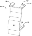
- FIGS. 6A-6C are a perspective view and a plan view, respectively, of the button 110 of the indwelling needle 10 of the first embodiment shown in Figs. 1A and 1B.
- the button 110 according to the present invention includes a pressing portion 111 and at least one pressing arm 112 extending from the pressing portion 111 in the radial direction (ie, the radial direction of the handle 20).
- the number of the pressing arms 112 is the same as the number of the elastic arms 35 of the needle holder 32 so as to cooperate with each other to enhance safety.
- the button 110 includes two squeeze arms 112. The end of each of the squeeze arms 112 has a thickened portion 113.
- the button 110 also includes at least one drive arm 114 that extends radially from the pressing portion 111 (ie, the radial direction of the handle 20).
- the number of the driving arms 114 is at least one, and may be less than or equal to the number of the elastic arms 35 of the needle holder 32 so as to cooperate with each other.
- the button 110 includes two drive arms 114, and the drive arm 114 is located outside of the squeeze arm 112.
- the drive arm 114 has an angled end 115. When the button 110 is depressed, the drive arm 114 will urge the resilient arm 35 in a radially inward direction to disengage the resilient arm 35 from engagement with the card 28.
- the drive arm 114 disengages the resilient arm 35 from engagement with the card 28 and the squeeze arm 112 is used to press the resilient arm 35 further against the card 28, Therefore, in some embodiments, the button may be provided with no pressing arm, but only the driving arm, and the elastic arm is pressed against the card by its own elastic force.
- 9A, 9B, and 9C show the cooperative relationship between the button and other members in the case where the safety mechanism of the indwelling needle of the first embodiment is not depressed.
- 10A to 10H show the cooperative relationship between the button and other members in the case where the safety mechanism of the indwelling needle of the first embodiment is just pressed.
- FIG. 9B is an enlarged view of a portion inside the two-dot chain line frame of FIG. 9A
- FIG. 9C is a cross-sectional view taken along line 9AA-9AA of FIG. 9B.
- the thickened portion 113 at the end pushes the resilient arm 35 radially outward, thereby causing the radially outwardly projecting engagement portion 36 of the resilient arm 35 to snap onto the inner wall of the distal portion 23 of the handle 20.
- the card is at 28.
- the driving arm 114 is located outside the elastic arm 35 (see FIGS. 9B and 9C) and has not been in contact with the elastic arm 35. Due to the pushing of the thickened portion 113 of the end of the pressing arm 112 and the elasticity of the elastic arm 35 itself, the elastic arm 35 firmly abuts against the card table 28, thereby the needle and the needle The seat assembly 30 remains in this position and the puncture needle 31 extends beyond the catheter 81.
- FIGS. 10C, 10D, 10E, and 10F show in detail the relationship between the resilient arm 35, the distal portion 23 of the handle 20, and the button 110 just after the button 110 has been depressed. Where only a portion of the button 110 is shown in FIG.
- a portion of the drive arm 114 is removed to show the rearwardly squeezed arm 112, and a portion of the upper portion of the squeeze arm 112 is removed for clear display and the end of the resilient arm 35. 37 relationship.
- Fig. 10F is the same as that shown in Fig. 10E except that it is viewed from the other side. As shown in FIGS. 10C to 10F, after the button 110 is pressed, the pressing arm 112 of the button 110 moves forward, and the thickened portion 113 that previously abuts against the elastic arm 35 moves through the gap 50 to the end of the elastic arm 35.
- the thickness of the end 37 of the resilient arm 35 is smaller than the width of the body portion of the resilient arm 35 to facilitate the thickening of the portion 113 through the gap 50
- the elastic arm 35 is no longer pressed radially outward to the card table 28, and the elastic arm 35 is inwardly elasticized due to its own elasticity. Back, off the deck 28.
- both the pressing arm 112 and the driving arm 114 are moved forward, and the inclined end portion 115 of the driving arm 114 is brought close to the elastic arm.
- the end 37 of the 35, the inclined side of the inclined end 115 gradually urges the resilient arm 35 to move radially inwardly, thereby assisting the engagement portion 36 of the resilient arm 35 from disengaging from the card 28. Since the resilient arm 35 is disengaged from the distal portion 23 of the handle 20 and the interior of the handle 20 is vacuumed, the needle and hub assembly 30 is retracted into the lumen 21 of the handle 20, as shown in Figure 10G and 10H is shown.
- 11A and 11B are perspective views of an unused indwelling needle 10' viewed from different directions in accordance with a second embodiment of the present invention.
- 12A and 12B are longitudinal cross-sectional views of the indwelling needle of the second embodiment shown in Figs. 11A and 11B taken along different cross sections.
- the structure and configuration of the proximal portion of the handle 20', the catheter and catheter hub assembly 80', etc. are the same as those of the first embodiment of the present invention, and the same portion will not Let me repeat. Only different features are described.
- 13A, 13B, and 13C are a perspective view and a cross-sectional view, respectively, of the protective cover 11' of the indwelling needle 10' of the second embodiment shown in Figs. 11A and 11B.
- the shape of the protective sheath 11' is also substantially the same as the shape of the distal portion of the indwelling needle 10' (or the distal portion of the handle 20' and the catheter and catheter hub assembly), and the underside of the protective sheath 11' has A portion is removed to fit over the distal portion of the indwelling needle 10' and a slit 15' is left over the protective sheath 11' for snapping onto the tab 85' of the catheter and catheter hub assembly 80'.
- the distal portion of the handle of the indwelling needle of the second embodiment, the needle hub, and the button of the safety mechanism are specifically described below.
- 14A, 14B, 14C, and 14D are a perspective view of the needle hub 32' of the indwelling needle 10' of the second embodiment shown in Figs. 11A and 11B, respectively, and a longitudinal cross-sectional view taken from a different direction.
- the hub 32' also has a hub body having a generally hollow cylinder having a reduced diameter portion 33' on the distal side of the hub body, and the hub body also has a resilient arm that flares radially outwardly. 35'.
- the number of resilient arms 35' may also be one or more than two, as long as it can be mated with a corresponding portion of the handle 20', and
- the cylinder of the hub body of the hub 32' is preferably a cylinder, but may be other prisms.
- a plurality of ribs or ribs 33a' are provided around the reduced diameter portion 33' of the hub 32', and the number of ribs or ribs 33a' corresponds to the notch 26a' of the flower hole 26' or Less than the number of notches 26a'.
- the reduced diameter portion 33' is formed with a shoulder 34' with respect to the hub body.
- the resilient arms 35' of the hub 32' are flared radially outward from the hub body and leave sufficient clearance 50' between the resilient arms 35' and the hub body. It will be understood by those skilled in the art that the formation of the void may be because the elastic arm 35' is flared outwardly, as shown in FIGS.
- the thinning is made to form a large gap with the elastic arm.
- the resilient arm 35' is radially outwardly flared from the hub body and extends from the distal to the proximal direction, having a latching portion 36' on the distal side of the resilient arm, the latching portion 36' having a radially outward direction Protrusion 37'. Further, at the proximal end of the hub 32', there is an engaging piece 47' on one side of the hub body.
- the hub 32' is hollow with a lumen therethrough.
- the penetrating lumen is divided into two segments, wherein the distal segment lumen 45' at the reduced diameter portion 33' of the hub 32' is adapted to receive and secure the puncture needle 31', whereby the hollow needle 31'
- the lumen communicates with the proximal section lumen 46' of the hub 32' such that blood can flow into the proximal section lumen 46' of the hub 32' after the needle 31' has been punctured into the vessel, prompting the user .
- 15A, 15B, 15C, 15D, and 15E are perspective views of the base 38' of the hub 32' of the indwelling needle 10' of the second embodiment shown in Figs. 11A and 11B, respectively, and from different cross sections. Cut longitudinal section view.
- the base 38' includes an upper disc 39', a lower disc 40', and a cylindrical section 41' connecting the upper disc 39' and the lower disc 40'.
- a plunger 43' is eccentrically disposed on the upper surface of the upper disc 39', and at least one engaging piece 42' is also provided, and two engaging pieces 42' are shown.
- the lower disc 40' may be provided with an inclined portion 40a' to facilitate assembly with a vacuum sealing plug.
- a reinforcing rib or rib 44' may be provided on the lower surface of the upper disc 39'.
- the plunger 43' blocks the proximal end of the lumen of the hub 32', preventing flow into the hub. Blood leaks within the proximal segment lumen 46' of 32'.
- the engaging piece 47' of the hub body of the hub 32' and the engaging piece 42' of the upper disc 39' of the base 38' are engaged with each other, preventing the hub body of the hub 32' from being opposite to the base 38' motion.
- the safety mechanism 100' includes a card table 28' disposed on the inner side wall of the distal portion 23' of the hollow handle 20'; at least one elastically disposed radially outwardly of the needle seat 32'
- the arm 35', the end portion of the resilient arm has a convex engaging portion 36' for engaging the card table 28';
- the button 110' is disposed at the distal portion 23' of the handle 20' Above, when the button 110' is depressed, the button 110' will push the resilient arm 35' radially inwardly such that the engaging portion 36' of the resilient arm 35' disengages from the card post 28'.
- buttons 16A and 16B are perspective views of the button 110' of the indwelling needle 10' of the second embodiment shown in Figs. 11A and 11B, respectively.
- the button 110' according to the present invention includes a curved sheet-like pressing portion 111' and at least one driving arm 114' extending from a lower portion of the pressing portion 111'.
- the number of the driving arms 114' and the number of the elastic arms 35 of the hub 32 are Consistent so that they work together.
- button 110' includes two drive arms 114' and drive arm 114' has an angled end 115'.
- the pressing portion 111' of the button 110' also has an engaging portion 112' for engaging with the receiving portion 25a' of the distal portion 23' of the handle 20'.
- Two joint portions 112' are shown in the drawing, and one of the joint portions 112' has a positioning protrusion 112a'.
- the joint can be at least one and can be other shapes as long as the button 110' is engaged to the receiving portion of the distal portion 23' of the handle 20'.
- FIG. 17A and 17B are perspective views of the distal portion 23' of the handle 20' of the indwelling needle 10' of the second embodiment shown in Figs. 11A and 11B, respectively.
- the distal portion 23' has an open proximal end 24' for engaging the open distal end of the proximal portion 22'.
- the distal end 25' of the distal portion 23' has a flower hole 26' formed therein, as shown in Figs. 17A and 17B, a plurality of notches 26a' are formed in the flower hole 26'.
- the shape of the flower hole 26' is not limited thereto as long as it is engaged with a corresponding portion of the needle holder.
- the side wall of the distal portion 23' has a button hole 27' for receiving the button 110' of the safety mechanism 100'.
- the inner wall of the distal portion 23' has an inwardly projecting card post 28' (see Fig. 17A) for engaging the resilient arm 35' of the hub 32'.
- the distal end of the distal end portion 25' of the distal portion 23' of the handle 20' i.e., the end surface on which the flower aperture 26' is formed
- a projection 29' is also formed to extend distally.
- the catheter and catheter hub assembly 80' When the catheter and catheter hub assembly 80' is assembled with the handle 20' and the needle and hub assembly 30', the proximal end face of the catheter hub body 83' and the distal end 25' of the distal portion 23' of the handle 20' The end face fits, the reduced diameter portion 33' of the hub 32' extends through the flower hole 26' in the distal end 25' of the distal portion 23' of the handle and extends into the lumen of the cylindrical catheter hub body 83'.
- the puncture needle 31' projects from the reduced diameter portion 33' of the hub 32', enters the catheter hub 82' and passes through the catheter lumen 81c' of the catheter 81', and the sharp end of the puncture needle 31' is from the catheter 81.
- the tapered end 81b' extends while the notch 88' is aligned with the projection 29' on the end face of the distal end 25' of the distal portion 23' of the handle 20', the button 110' being placed distal to the handle 20' In the side portion 23', wherein the pressing portion 111' of the button 110' is fitted into the button hole 27' of the distal portion 23', and the surface of the pressing portion 111' is not pressed when not pressed The two side edges of the distal portion 23' are flush.
- the engaging portion 36' of the resilient arm 35' of the hub 32' abuts against the card 28' on the inner wall of the distal portion 23'.
- FIGS. 11A and 11B are diagrams showing a state of use of the indwelling needle of the second embodiment shown in Figs. 11A and 11B, wherein Fig. 18A shows the indwelling needle 10' from which the protective sheath 11' has not been removed, and Fig. 18B has been removed.
- 18C is the indwelling needle 10' which pushes the catheter and the catheter hub assembly 80' distally
- Fig. 18D is the indwelling needle 10' which presses the button 110' of the lower safety mechanism 100'.
- 18E and 18F are the indwelling needles 10' in which the puncture needle 31' is in the retracted state and has been retracted, respectively.
- 19A and 19B are views showing the interaction between the driving arm of the button and the elastic arm of the needle holder when the button of the indwelling needle of the second embodiment shown in Figs. 11A and 11B is pressed.
- Figure 20 is a perspective view of an indwelling needle 10" that has not been used but has been removed, in accordance with a third embodiment of the present invention.
- Figures 21A and 21B are cut from different cross-sections in accordance with a third embodiment of the present invention.
- the structure and configuration of the proximal portion of the handle 20", the catheter and catheter hub assembly 80", and the like are the same as those of the first and second embodiments of the present invention, and the same portions will not be described again. Only different features are described.
- the distal portion of the handle of the indwelling needle of the third embodiment, the ferrule of the handle, the needle hub, and the button of the safety mechanism are specifically described below.
- 22A, 22B, and 22C are a perspective view of the needle hub 32" of the indwelling needle 10" of the third embodiment shown in Fig. 20, respectively, and a longitudinal cross-sectional view taken from a different side.
- the hub 32" also has a generally hollow cylindrical body for the body of the hub.
- the distal side has a reduced diameter portion 33"
- the hub body also has a resilient arm 35" that flares radially outward.
- the figure shows a resilient arm 35", but those skilled in the art will appreciate that the number of resilient arms 35" may also be one or more than two, as long as it can be mated with a corresponding portion of the handle 20" and the needle
- the cylinder of the hub body of the seat 32" is preferably a cylinder, but may be other prisms.
- the diametrically reduced portion 33" of the hub 32" is provided with a plurality of ribs or ribs 33a", the number of ribs or ribs 33a” and the distal end face of the distal portion 23" of the handle 20"
- the notch 26a" of the upper flower hole 26" corresponds to or is smaller than the number of the notches 26a".
- the reduced diameter portion 33" is formed with a shoulder 34" with respect to the hub body.
- the resilient arm 35" of the hub 32" is self-contained The hub body flares radially outwardly and leaves sufficient clearance 50" between the resilient arms 35" and the hub body.
- the voids may be formed either because the resilient arms 35" are outwardly
- the opening is large, as shown in Fig. 23A. It may also be because the wall thickness of the hub body is thinned here to form a large gap with the elastic arm.
- the resilient arm 35" is radially outwardly flared from the hub body and extends from the distal to the proximal direction, having a latching portion 36" on the distal side of the resilient arm, the latching portion 36" having a radially outward direction
- the raised card table 36a" and the wedge portion 37" extending from the card table 36a" in the longitudinal direction.
- Figure 24 is a cross-sectional view of the hub base 38" of the indwelling needle 10" of the third embodiment shown in Figure 20 .
- the base 38" includes an upper disc 39", a lower disc 40", and a cylindrical section 41" connecting the upper disc 39" and the lower disc 40".
- the upper surface of the upper disc 39" is concentrically provided with a plunger 43".
- the lower disc 40" may be provided with a sloped portion 40a" to facilitate assembly with a vacuum sealing plug.
- the plunger 43" blocks the proximal end of the lumen of the hub 32", preventing the flow into the hub. Blood leaks within the 32" proximal segment lumen 46".
- the handle 20" further includes a ferrule 20a" for engaging the engagement portion 36" of the resilient arm 35".
- the ferrule 20a” shown in Figure 21A is of cylindrical configuration, placed within the handle 20", the bottom of the barrel being placed at the proximal end of the handle 20" and the open end facing the hub 32" for receiving the hub 32", A vacuum is formed in the ferrule 20a" by the vacuum sealing plug 120". The edge 20a1" of the ferrule 20a" is engaged with the card 36a" (see figure). 25).
- the form of the ferrule 20a" is not limited thereto, and it may also be, for example, a cylinder that is open at both ends in the proximal portion of the handle 20", still forming a vacuum by the lumen 21" of the handle 20".
- FIG. 23A and 23B are perspective views of the distal portion 23" of the indwelling needle 10" of the third embodiment shown in Fig. 20, respectively.
- the distal portion 23" of the handle 20" is similar to that of the first embodiment, but the button 110" is formed by a portion of the side wall of the distal portion 23" that can be accessed by the distal end face and the side wall of the distal portion 23"
- the interposed hinge portion 111a" is pressed radially inwardly to urge the engaging portion 36" of the resilient arm 35" inwardly away from the ferrule 20a".
- Figure 25 is a partial enlarged view of Figure 21A showing the mating relationship between the button 110", the resilient arm 35" of the hub 32" and the ferrule 20a” when the safety mechanism is not activated.
- the reduced diameter portion 33" of the hub 32" disposed within the handle 20" extends from the flower opening 26" on the distal end face of the distal portion 23" of the handle 20"
- the elastic arm 35" of the needle seat 32" is opened radially outward, and is engaged at the edge 20a1" of the ferrule 20a” through the card table 36a
- the base of the needle seat 32" 38” is engaged with the vacuum sealing plug 120", and a vacuum is formed in the ferrule 20a”.
- the safety mechanism 100" is activated, that is, the button 110" (see Fig. 25) is pressed to retract the puncture needle 31".
- the button 110" is rotated inwardly about the hinge portion 111a
- the elastic arm is 35" is urged radially inwardly, thereby causing 35" to move radially inwardly, and the card table 36a" is disengaged from the edge 20a1" of the ferrule 20a", and the needle holder 32" and the puncture needle 31" are retracted by vacuum.
- Fig. 26 is a cross-sectional view showing the puncture needle of the indwelling needle of the third embodiment shown in Fig. 20 retracted into the handle after pressing the button.
- 27A, 27B, and 27C illustrate cross-sectional views of the indwelling needle 10"" of the fourth embodiment, the hub base 38"", and the O-ring, respectively, in accordance with a fourth embodiment of the present invention. Cutaway view.
- the fourth embodiment according to the present invention is substantially identical in structure to the third embodiment except that the structure of the base 38'' of the hub is different.
- the hub 32'' The base 38"" is a cylinder, and a small cylinder 39"" protrudes from the upper surface of the cylinder for blocking the proximal end of the hub 32'".
- a plurality of cylinders are formed on the circumference of the cylinder.
- the groove 40''' is for accommodating the O-ring 41''.
- the working principle of the fourth embodiment is identical to that of the third embodiment.
- the indwelling needle according to the present invention as previously described can be made of any suitable material, and the distal portion of the handle and the needle hub are transparent so as to be viewable by the user after the blood has entered the indwelling needle.
Landscapes
- Health & Medical Sciences (AREA)
- Life Sciences & Earth Sciences (AREA)
- Animal Behavior & Ethology (AREA)
- General Health & Medical Sciences (AREA)
- Biomedical Technology (AREA)
- Heart & Thoracic Surgery (AREA)
- Hematology (AREA)
- Engineering & Computer Science (AREA)
- Veterinary Medicine (AREA)
- Anesthesiology (AREA)
- Public Health (AREA)
- Vascular Medicine (AREA)
- Biophysics (AREA)
- Pulmonology (AREA)
- Infusion, Injection, And Reservoir Apparatuses (AREA)
- Media Introduction/Drainage Providing Device (AREA)
Abstract
Description
Claims (28)
- 一种用于留置针的安全机构,所述留置针包括中空手柄和至少部分地位于手柄内用于接收穿刺针的针座,其特征在于所述安全机构包括:设置于中空手柄的内侧的卡台;设置于针座上的径向向外张开的至少一个弹性臂,弹性臂的末端部分具有径向向外凸出的卡合部,所述卡合部用于与卡台接合;按钮,设置在手柄的远侧部分上,当按下按钮,按钮将沿径向向内方向推压所述弹性臂,使得所述弹性臂的卡合部与卡台脱离接合,同时借助中空手柄内的真空,使得针座以及伸出在手柄外的穿刺针缩回到中空手柄内。
- 如权利要求1所述的用于留置针的安全机构,其中,所述卡台设置在中空手柄的远侧部分的内壁上,所述弹性臂径向向外张开并从针座的近侧向远侧方向延伸。
- 如权利要求2所述的用于留置针的安全机构,其中,所述按钮包括按压部以及从按压部沿径向延伸的至少一个挤压臂,所述挤压臂的末端具有增厚部分,在按钮未被按压下时,挤压臂伸入针座的主体和从主体径向向外张开的弹性臂之间的空隙,利用增厚部分将弹性臂压靠到卡台上,当按钮被按压下之后,挤压臂的增厚部分伸出所述空隙之外,不再径向向外挤压弹性臂。
- 如权利要求3所述的用于留置针的安全机构,其中,所述按钮还包括从按压部沿径向延伸的至少一个驱动臂,所述驱动臂具有倾斜的端部并且布置在挤压臂的外侧,在按钮未被按压下时,驱动臂位于弹性臂的端头外侧但并未与之接触,当按钮被按压下之后,随着挤压臂的增厚部分伸出所述空隙之外不再径向向外挤压弹性臂,位于外侧的驱动臂的倾斜的端部的倾斜侧逐渐径向向内挤压弹性臂。
- 如权利要求3或4所述的用于留置针的安全机构,其中,所 述弹性臂的端头的宽度小于弹性臂的主体部分的宽度。
- 如权利要求2所述的用于留置针的安全机构,其中,所述按钮具有沿径向延伸的至少一个驱动臂,所述驱动臂具有倾斜的端部并且布置在弹性臂的外侧,当按钮被按压下之后,驱动臂的倾斜的端部的倾斜侧逐渐径向向内挤压弹性臂。
- 如权利要求3或4所述的用于留置针的安全机构,其中,所述弹性臂为两个,所述驱动臂为一个或两个。
- 如权利要求1所述的用于留置针的安全机构,其中,所述卡台设置在中空手柄的远侧部分的内壁上,所述弹性臂径向向外张开并从针座的远侧向近侧方向延伸。
- 如权利要求8所述的用于留置针的安全机构,其中,所述按钮具有沿径向延伸的至少一个驱动臂,所述驱动臂具有倾斜的端部并且布置在弹性臂的外侧,当按钮被按压下之后,驱动臂的倾斜的端部的倾斜侧逐渐径向向内挤压弹性臂。
- 如权利要求9所述的用于留置针的安全机构,其中,所述驱动臂为两个。
- 如权利要求1所述的用于留置针的安全机构,其中,所述中空手柄包括设置在其内部的筒形的卡套,卡套的边缘延伸到手柄的远侧部分处并且边缘形成为所述卡台,所述弹性臂径向向外张开并从针座的远侧向近侧方向延伸。
- 如权利要求11所述的用于留置针的安全机构,其中,所述按钮由手柄的远侧部分的侧壁形成,当按压下按钮时,按钮将弹性臂的卡合部推离卡套的边缘。
- 如权利要求1所述的用于留置针的安全机构,其中,所述中空手柄的远侧部分和针座是透明材料制成的。
- 一种留置针,所述留置针包括:中空的手柄;至少部分地位于手柄内的针座;固定于所述针座的远端的穿刺针;设置在穿刺针外部的导管和导管毂;安全机构,所述安全机构包括:设置于所述手柄的内侧的卡台;设置于针座上的径向向外张开的至少一个弹性臂,弹性臂的末端部分具有径向向外凸出的卡合部,所述卡合部用于与卡台接合;按钮,设置在手柄的远侧部分上,当按下按钮,按钮将沿径向向内方向推压所述弹性臂,使得所述弹性臂的卡合部与卡台脱离接合,同时借助中空手柄内的真空,使得伸出在手柄外的穿刺针缩回到中空手柄内。
- 如权利要求14所述的留置针,其中,所述卡台设置在中空手柄的远侧部分的内壁上,所述弹性臂径向向外张开并从针座的近侧向远侧方向延伸。
- 如权利要求15所述的留置针,其中,所述按钮包括按压部以及从按压部沿径向延伸的至少一个挤压臂,所述挤压臂的末端具有增厚部分,在按钮未被按压下时,挤压臂伸入针座的主体和从主体径向向外张开的弹性臂之间的空隙,利用增厚部分将弹性臂压靠到卡台上,当按钮被按压下之后,挤压臂的增厚部分伸出所述空隙之外,不再径向向外挤压弹性臂。
- 如权利要求16所述的留置针,其中,所述按钮还包括从按压部沿径向延伸的至少一个驱动臂,所述驱动臂具有倾斜的端部并且布置在挤压臂的外侧,在按钮未被按压下时,驱动臂位于弹性臂的端头外侧但并未与之接触,当按钮被按压下之后,随着挤压臂的增厚部分伸出所述空隙之外不再径向向外挤压弹性臂,位于外侧的驱动臂的倾斜的端部的倾斜侧逐渐径向向内挤压弹性臂。
- 如权利要求16或17所述的留置针,其中,所述弹性臂的端头的宽度小于弹性臂的主体部分的宽度。
- 如权利要求15所述的留置针,其中,所述按钮具有沿径向延伸的至少一个驱动臂,所述驱动臂具有倾斜的端部并且布置在弹性臂的外侧,当按钮被按压下之后,驱动臂的倾斜的端部的倾斜侧逐渐径向向内挤压弹性臂。
- 如权利要求16或17所述的留置针,其中,所述弹性臂为两个,所述驱动臂为一个或两个。
- 如权利要求14所述的留置针,其中,所述卡台设置在中空手柄的远侧部分的内壁上,所述弹性臂径向向外张开并从针座的远侧向近侧方向延伸。
- 如权利要求21所述的留置针,其中,所述按钮具有至少一个驱动臂,所述驱动臂具有倾斜的端部并且布置在弹性臂的外侧,当按钮被按压下之后,驱动臂的倾斜的端部的倾斜侧逐渐径向向内挤压弹性臂。
- 如权利要求22所述的留置针,其中,所述驱动臂为两个。
- 如权利要求14所述的留置针,其中,所述中空手柄包括设置在其内部的筒形的卡套,卡套的边缘延伸到手柄的远侧部分处并且边缘形成为所述卡台,所述弹性臂径向向外张开并从针座的远侧向近侧方向延伸。
- 如权利要求24所述的留置针,其中,所述按钮由手柄的远侧部分的侧壁形成,当按压下按钮时,按钮将弹性臂的卡合部推离卡套的边缘。
- 如权利要求14所述的留置针,其中,所述中空手柄的远侧部分和针座是透明材料制成的。
- 如权利要求14所述的留置针,其中,所述针座的基座和中空手柄的内腔之间设置有真空密封塞,以便在手柄内形成真空。
- 如权利要求24所述的留置针,其中,所述针座的基座和中空手柄的卡套的内腔之间设置有真空密封塞,以便在手柄的卡套内形成真空。
Priority Applications (3)
| Application Number | Priority Date | Filing Date | Title |
|---|---|---|---|
| EP16813740.4A EP3315152A4 (en) | 2015-06-25 | 2016-06-24 | SECURITY MECHANISM FOR REMAINING NEEDLE AND REMAINING NEEDLE THEREOF |
| JP2017564368A JP6789249B2 (ja) | 2015-06-25 | 2016-06-24 | 留置針のための安全機構及び安全機構を有する留置針 |
| US15/580,461 US10773018B2 (en) | 2015-06-25 | 2016-06-24 | Safety mechanism for a retaining needle and a retaining needle having the safety mechanism |
Applications Claiming Priority (2)
| Application Number | Priority Date | Filing Date | Title |
|---|---|---|---|
| CN201520454957.3U CN205041892U (zh) | 2015-06-25 | 2015-06-25 | 用于留置针的安全机构以及带有该安全机构的留置针 |
| CN201520454957.3 | 2015-06-25 |
Publications (1)
| Publication Number | Publication Date |
|---|---|
| WO2016206624A1 true WO2016206624A1 (zh) | 2016-12-29 |
Family
ID=55335513
Family Applications (1)
| Application Number | Title | Priority Date | Filing Date |
|---|---|---|---|
| PCT/CN2016/087002 WO2016206624A1 (zh) | 2015-06-25 | 2016-06-24 | 用于留置针的安全机构以及带有该安全机构的留置针 |
Country Status (7)
| Country | Link |
|---|---|
| US (1) | US10773018B2 (zh) |
| EP (1) | EP3315152A4 (zh) |
| JP (1) | JP6789249B2 (zh) |
| CN (1) | CN205041892U (zh) |
| AR (1) | AR105123A1 (zh) |
| TW (1) | TWI661848B (zh) |
| WO (1) | WO2016206624A1 (zh) |
Families Citing this family (4)
| Publication number | Priority date | Publication date | Assignee | Title |
|---|---|---|---|---|
| CN205041892U (zh) | 2015-06-25 | 2016-02-24 | 千禧光医疗有限公司 | 用于留置针的安全机构以及带有该安全机构的留置针 |
| CN106310446B (zh) * | 2015-06-25 | 2021-01-01 | 千禧光医疗有限公司 | 用于留置针的安全机构以及带有该安全机构的留置针 |
| CN106362263A (zh) * | 2016-08-30 | 2017-02-01 | 苏州鱼跃医疗科技有限公司 | 用于导管组件的引入针保护装置、导管组件及留置针 |
| EP3603706A4 (en) | 2017-03-24 | 2020-10-07 | Sol-Millennium Medical HK Limited | SAFE INJECTION DEVICE AND SECURITY MECHANISM APPLIED TO IT |
Citations (6)
| Publication number | Priority date | Publication date | Assignee | Title |
|---|---|---|---|---|
| CN1171745A (zh) * | 1995-01-10 | 1998-01-28 | 特殊健康产品公司 | 自行收回医用针头装置和方法 |
| CN1277874A (zh) * | 1999-06-22 | 2000-12-27 | 刘文能 | 多用途安全自动输液静脉留置针 |
| CN1803209A (zh) * | 2005-01-12 | 2006-07-19 | 宇仁医疗器材科技股份有限公司 | 安全静脉留置针导管 |
| US20070073237A1 (en) * | 2003-07-31 | 2007-03-29 | Aaron Rodd | Cannula/catheter introducer |
| CN103239775A (zh) * | 2012-02-13 | 2013-08-14 | 王治明 | 静脉留置针 |
| CN205041892U (zh) * | 2015-06-25 | 2016-02-24 | 千禧光医疗有限公司 | 用于留置针的安全机构以及带有该安全机构的留置针 |
Family Cites Families (11)
| Publication number | Priority date | Publication date | Assignee | Title |
|---|---|---|---|---|
| US5823997A (en) | 1995-01-10 | 1998-10-20 | Specialized Health Products, Inc. | Medical needle safety apparatus and methods |
| US5487734A (en) | 1995-01-10 | 1996-01-30 | Specialized Health Products, Inc. | Self retracting catheter needle apparatus and methods |
| US5656031A (en) | 1995-01-10 | 1997-08-12 | Specialized Health Products, Inc. | Medical syringe and self retracting needle apparatus |
| US5836917A (en) | 1995-01-10 | 1998-11-17 | Specialized Health Products, Inc. | Self retracting medical needle apparatus and methods |
| US5672161A (en) | 1996-09-20 | 1997-09-30 | Becton, Dickinson And Company | Needle assembly having single-handedly activated needle barrier |
| US6015397A (en) | 1997-06-20 | 2000-01-18 | Elson; Edward E. | Needle point guard safety cap assembly |
| US6086563A (en) * | 1999-01-13 | 2000-07-11 | Becton, Dickinson And Company | Needle retraction mechanism with push start retraction |
| CA2645972A1 (en) | 2007-12-14 | 2009-06-14 | Tyco Healthcare Group Lp | Safety needle assembly |
| US10300215B2 (en) | 2014-08-04 | 2019-05-28 | Nipro Corporation | Needle assembly |
| CN106237454A (zh) | 2016-08-30 | 2016-12-21 | 昆山翔和元自动化科技有限公司 | 一种安全针结构 |
| EP3603706A4 (en) | 2017-03-24 | 2020-10-07 | Sol-Millennium Medical HK Limited | SAFE INJECTION DEVICE AND SECURITY MECHANISM APPLIED TO IT |
-
2015
- 2015-06-25 CN CN201520454957.3U patent/CN205041892U/zh not_active Expired - Fee Related
-
2016
- 2016-06-24 EP EP16813740.4A patent/EP3315152A4/en not_active Withdrawn
- 2016-06-24 US US15/580,461 patent/US10773018B2/en active Active
- 2016-06-24 TW TW105120031A patent/TWI661848B/zh not_active IP Right Cessation
- 2016-06-24 WO PCT/CN2016/087002 patent/WO2016206624A1/zh active Application Filing
- 2016-06-24 AR ARP160101906A patent/AR105123A1/es unknown
- 2016-06-24 JP JP2017564368A patent/JP6789249B2/ja active Active
Patent Citations (6)
| Publication number | Priority date | Publication date | Assignee | Title |
|---|---|---|---|---|
| CN1171745A (zh) * | 1995-01-10 | 1998-01-28 | 特殊健康产品公司 | 自行收回医用针头装置和方法 |
| CN1277874A (zh) * | 1999-06-22 | 2000-12-27 | 刘文能 | 多用途安全自动输液静脉留置针 |
| US20070073237A1 (en) * | 2003-07-31 | 2007-03-29 | Aaron Rodd | Cannula/catheter introducer |
| CN1803209A (zh) * | 2005-01-12 | 2006-07-19 | 宇仁医疗器材科技股份有限公司 | 安全静脉留置针导管 |
| CN103239775A (zh) * | 2012-02-13 | 2013-08-14 | 王治明 | 静脉留置针 |
| CN205041892U (zh) * | 2015-06-25 | 2016-02-24 | 千禧光医疗有限公司 | 用于留置针的安全机构以及带有该安全机构的留置针 |
Non-Patent Citations (1)
| Title |
|---|
| See also references of EP3315152A4 * |
Also Published As
| Publication number | Publication date |
|---|---|
| TWI661848B (zh) | 2019-06-11 |
| TW201700121A (zh) | 2017-01-01 |
| EP3315152A1 (en) | 2018-05-02 |
| JP6789249B2 (ja) | 2020-11-25 |
| CN205041892U (zh) | 2016-02-24 |
| US20180318500A1 (en) | 2018-11-08 |
| JP2018518275A (ja) | 2018-07-12 |
| EP3315152A4 (en) | 2019-03-27 |
| AR105123A1 (es) | 2017-09-06 |
| US10773018B2 (en) | 2020-09-15 |
Similar Documents
| Publication | Publication Date | Title |
|---|---|---|
| US10406328B2 (en) | Needle for bloodless IV | |
| WO2016206624A1 (zh) | 用于留置针的安全机构以及带有该安全机构的留置针 | |
| US20200146605A1 (en) | Releaseable catheter hub retainer | |
| JP3796514B2 (ja) | 収納自在な穿刺針を備えた医療用器具及び同医療用器具の製造方法 | |
| US10548522B2 (en) | Releaseable catheter hub retainer | |
| JP3958579B2 (ja) | 血液採集セット | |
| US11865320B2 (en) | Safe cannulation devices, methods, and systems | |
| US20140200522A1 (en) | Safe vein detained needle | |
| WO2021168781A1 (zh) | 一种安全胰岛素笔针 | |
| JP2022546064A (ja) | 延長留置、正中線カテーテルおよび関連する方法 | |
| CN106310446B (zh) | 用于留置针的安全机构以及带有该安全机构的留置针 | |
| CN212415738U (zh) | 一种采血针封闭接头组件 | |
| GB2400323A (en) | Safety syringe | |
| JP2016077424A (ja) | 留置針組立体 | |
| WO2018209498A1 (zh) | 前伸针杆安全型开放式留置针 | |
| JPH0357248Y2 (zh) | ||
| CN211512955U (zh) | 一种一次性卡扣型安全胰岛素针头 | |
| JP3035912U (ja) | 注射針保護キャップ | |
| CN212522678U (zh) | 一次性使用经外周穿刺中等长度导管 | |
| CN216797780U (zh) | 一种助针器 | |
| CN217612292U (zh) | 一种具备防刺功能头皮针 | |
| CN203935471U (zh) | 自排气静脉针 | |
| CN115252958A (zh) | 一次性使用的长导管套针留置装置 | |
| CN111408021A (zh) | 一次性使用经外周穿刺中等长度导管 | |
| WO2020077899A1 (zh) | 一种按压式采血针 |
Legal Events
| Date | Code | Title | Description |
|---|---|---|---|
| 121 | Ep: the epo has been informed by wipo that ep was designated in this application |
Ref document number: 16813740 Country of ref document: EP Kind code of ref document: A1 |
|
| WWE | Wipo information: entry into national phase |
Ref document number: 15580461 Country of ref document: US |
|
| ENP | Entry into the national phase |
Ref document number: 2017564368 Country of ref document: JP Kind code of ref document: A |
|
| NENP | Non-entry into the national phase |
Ref country code: DE |
|
| WWE | Wipo information: entry into national phase |
Ref document number: 2016813740 Country of ref document: EP |