WO2016204252A1 - 内視鏡 - Google Patents
内視鏡 Download PDFInfo
- Publication number
- WO2016204252A1 WO2016204252A1 PCT/JP2016/068008 JP2016068008W WO2016204252A1 WO 2016204252 A1 WO2016204252 A1 WO 2016204252A1 JP 2016068008 W JP2016068008 W JP 2016068008W WO 2016204252 A1 WO2016204252 A1 WO 2016204252A1
- Authority
- WO
- WIPO (PCT)
- Prior art keywords
- distal end
- treatment instrument
- endoscope
- ultrasonic
- endoscope according
- Prior art date
Links
Images


Classifications
-
- A—HUMAN NECESSITIES
- A61—MEDICAL OR VETERINARY SCIENCE; HYGIENE
- A61B—DIAGNOSIS; SURGERY; IDENTIFICATION
- A61B8/00—Diagnosis using ultrasonic, sonic or infrasonic waves
- A61B8/12—Diagnosis using ultrasonic, sonic or infrasonic waves in body cavities or body tracts, e.g. by using catheters
-
- A—HUMAN NECESSITIES
- A61—MEDICAL OR VETERINARY SCIENCE; HYGIENE
- A61B—DIAGNOSIS; SURGERY; IDENTIFICATION
- A61B1/00—Instruments for performing medical examinations of the interior of cavities or tubes of the body by visual or photographical inspection, e.g. endoscopes; Illuminating arrangements therefor
- A61B1/00002—Operational features of endoscopes
- A61B1/00011—Operational features of endoscopes characterised by signal transmission
-
- A—HUMAN NECESSITIES
- A61—MEDICAL OR VETERINARY SCIENCE; HYGIENE
- A61B—DIAGNOSIS; SURGERY; IDENTIFICATION
- A61B1/00—Instruments for performing medical examinations of the interior of cavities or tubes of the body by visual or photographical inspection, e.g. endoscopes; Illuminating arrangements therefor
- A61B1/00064—Constructional details of the endoscope body
- A61B1/00071—Insertion part of the endoscope body
- A61B1/0008—Insertion part of the endoscope body characterised by distal tip features
- A61B1/00097—Sensors
-
- A—HUMAN NECESSITIES
- A61—MEDICAL OR VETERINARY SCIENCE; HYGIENE
- A61B—DIAGNOSIS; SURGERY; IDENTIFICATION
- A61B1/00—Instruments for performing medical examinations of the interior of cavities or tubes of the body by visual or photographical inspection, e.g. endoscopes; Illuminating arrangements therefor
- A61B1/00064—Constructional details of the endoscope body
- A61B1/00071—Insertion part of the endoscope body
- A61B1/0008—Insertion part of the endoscope body characterised by distal tip features
- A61B1/00098—Deflecting means for inserted tools
-
- A—HUMAN NECESSITIES
- A61—MEDICAL OR VETERINARY SCIENCE; HYGIENE
- A61B—DIAGNOSIS; SURGERY; IDENTIFICATION
- A61B1/00—Instruments for performing medical examinations of the interior of cavities or tubes of the body by visual or photographical inspection, e.g. endoscopes; Illuminating arrangements therefor
- A61B1/005—Flexible endoscopes
- A61B1/0051—Flexible endoscopes with controlled bending of insertion part
-
- A—HUMAN NECESSITIES
- A61—MEDICAL OR VETERINARY SCIENCE; HYGIENE
- A61B—DIAGNOSIS; SURGERY; IDENTIFICATION
- A61B1/00—Instruments for performing medical examinations of the interior of cavities or tubes of the body by visual or photographical inspection, e.g. endoscopes; Illuminating arrangements therefor
- A61B1/012—Instruments for performing medical examinations of the interior of cavities or tubes of the body by visual or photographical inspection, e.g. endoscopes; Illuminating arrangements therefor characterised by internal passages or accessories therefor
- A61B1/018—Instruments for performing medical examinations of the interior of cavities or tubes of the body by visual or photographical inspection, e.g. endoscopes; Illuminating arrangements therefor characterised by internal passages or accessories therefor for receiving instruments
-
- G—PHYSICS
- G02—OPTICS
- G02B—OPTICAL ELEMENTS, SYSTEMS OR APPARATUS
- G02B23/00—Telescopes, e.g. binoculars; Periscopes; Instruments for viewing the inside of hollow bodies; Viewfinders; Optical aiming or sighting devices
- G02B23/24—Instruments or systems for viewing the inside of hollow bodies, e.g. fibrescopes
- G02B23/2476—Non-optical details, e.g. housings, mountings, supports
-
- A—HUMAN NECESSITIES
- A61—MEDICAL OR VETERINARY SCIENCE; HYGIENE
- A61B—DIAGNOSIS; SURGERY; IDENTIFICATION
- A61B1/00—Instruments for performing medical examinations of the interior of cavities or tubes of the body by visual or photographical inspection, e.g. endoscopes; Illuminating arrangements therefor
- A61B1/00002—Operational features of endoscopes
- A61B1/00004—Operational features of endoscopes characterised by electronic signal processing
- A61B1/00009—Operational features of endoscopes characterised by electronic signal processing of image signals during a use of endoscope
- A61B1/000095—Operational features of endoscopes characterised by electronic signal processing of image signals during a use of endoscope for image enhancement
-
- A—HUMAN NECESSITIES
- A61—MEDICAL OR VETERINARY SCIENCE; HYGIENE
- A61B—DIAGNOSIS; SURGERY; IDENTIFICATION
- A61B1/00—Instruments for performing medical examinations of the interior of cavities or tubes of the body by visual or photographical inspection, e.g. endoscopes; Illuminating arrangements therefor
- A61B1/00064—Constructional details of the endoscope body
-
- A—HUMAN NECESSITIES
- A61—MEDICAL OR VETERINARY SCIENCE; HYGIENE
- A61B—DIAGNOSIS; SURGERY; IDENTIFICATION
- A61B1/00—Instruments for performing medical examinations of the interior of cavities or tubes of the body by visual or photographical inspection, e.g. endoscopes; Illuminating arrangements therefor
- A61B1/00163—Optical arrangements
- A61B1/00165—Optical arrangements with light-conductive means, e.g. fibre optics
-
- A—HUMAN NECESSITIES
- A61—MEDICAL OR VETERINARY SCIENCE; HYGIENE
- A61B—DIAGNOSIS; SURGERY; IDENTIFICATION
- A61B1/00—Instruments for performing medical examinations of the interior of cavities or tubes of the body by visual or photographical inspection, e.g. endoscopes; Illuminating arrangements therefor
- A61B1/005—Flexible endoscopes
- A61B1/0051—Flexible endoscopes with controlled bending of insertion part
- A61B1/0057—Constructional details of force transmission elements, e.g. control wires
-
- A—HUMAN NECESSITIES
- A61—MEDICAL OR VETERINARY SCIENCE; HYGIENE
- A61B—DIAGNOSIS; SURGERY; IDENTIFICATION
- A61B1/00—Instruments for performing medical examinations of the interior of cavities or tubes of the body by visual or photographical inspection, e.g. endoscopes; Illuminating arrangements therefor
- A61B1/012—Instruments for performing medical examinations of the interior of cavities or tubes of the body by visual or photographical inspection, e.g. endoscopes; Illuminating arrangements therefor characterised by internal passages or accessories therefor
-
- G—PHYSICS
- G02—OPTICS
- G02B—OPTICAL ELEMENTS, SYSTEMS OR APPARATUS
- G02B23/00—Telescopes, e.g. binoculars; Periscopes; Instruments for viewing the inside of hollow bodies; Viewfinders; Optical aiming or sighting devices
- G02B23/24—Instruments or systems for viewing the inside of hollow bodies, e.g. fibrescopes
- G02B23/26—Instruments or systems for viewing the inside of hollow bodies, e.g. fibrescopes using light guides
Definitions
- the present invention relates to an endoscope.
- Patent Literature 1 includes a multi-joint structure treatment instrument elevator in which flat members are sequentially connected in a rotatable manner, and a raising operation wire connected to the distal end of the treatment instrument elevator.
- An endoscope is disclosed. In this endoscope, when the wire is pulled to the proximal end side by a raising operation of a user such as a doctor, the plate-like member of the treatment instrument raising base is sequentially rotated to raise the treatment instrument.
- the present invention has been made in view of the above, and an object thereof is to provide an endoscope having good cleaning efficiency.
- an endoscope includes an insertion portion that is inserted into a subject and an operation that is connected to the proximal end side of the insertion portion.
- a treatment instrument inserted at the distal end of the insertion portion, and an observation means for observing the subject, and a treatment instrument for treating the subject.
- the distal end bending portion is independent of a direction in which the observation means observes a direction in which the treatment tool protrudes in response to the raising operation of the operation portion. It is characterized by changing.
- an endoscope according to an aspect of the present invention includes one wire that is disposed along a direction in which the insertion portion extends and is connected to the operation portion, and the distal end portion of the wire includes the wire It is characterized by being covered with an exterior part.
- the endoscope according to one aspect of the present invention is characterized in that the tip bending portion has an elliptical cross section perpendicular to a direction in which the insertion portion extends.
- the endoscope according to one aspect of the present invention is characterized in that it includes two wires respectively disposed along a direction in which the insertion portion extends.
- the endoscope according to one aspect of the present invention includes four wires respectively disposed along a direction in which the insertion portion extends.
- the endoscope according to one aspect of the present invention is characterized in that the distal end bending portion has a pipe made of a super elastic alloy in which a slit for reducing power required for the bending operation is formed.
- an endoscope includes a hard distal end portion that is disposed on a distal end side of the insertion portion and has an opening formed therein, and in a cross section orthogonal to a direction in which the insertion portion extends, The tip bending portion in an initial state that is not curved is accommodated in the opening.
- the observation unit includes an optical system that collects the light reflected by the observation target and an imaging element that converts the collected light and outputs an electrical signal.
- An imaging unit or an ultrasonic transducer unit that receives an ultrasonic wave reflected from an observation target and outputs an electrical signal is included.
- an endoscope with good cleaning efficiency can be realized.
- FIG. 1 is a schematic diagram showing a configuration of an ultrasonic diagnostic system including an ultrasonic endoscope according to Embodiment 1 of the present invention.
- FIG. 2 is a schematic partial cross-sectional view of the distal end hard portion of the ultrasonic endoscope shown in FIG.
- FIG. 3 is a cross-sectional view corresponding to the line A1-A1 of FIG. 4 is a cross-sectional view corresponding to the line B1-B1 of FIG.
- FIG. 5 is a view for explaining the structure of the distal end bending portion of FIG.
- FIG. 6 is a schematic partial cross-sectional view showing a state in which the distal end portion of the treatment instrument channel of FIG. 2 raises the treatment instrument.
- FIG. 1 is a schematic diagram showing a configuration of an ultrasonic diagnostic system including an ultrasonic endoscope according to Embodiment 1 of the present invention.
- FIG. 2 is a schematic partial cross-sectional view of the distal end hard portion of the ultrasonic
- FIG. 7 is a view for explaining another structure of the distal end bending portion of FIG.
- FIG. 8 is a schematic diagram illustrating a configuration of a main part of an ultrasonic diagnostic system including the ultrasonic endoscope according to the second embodiment of the present invention.
- FIG. 9 is a cross-sectional view corresponding to line B2-B2 of FIG.
- FIG. 10 is a schematic diagram illustrating a configuration of a main part of an ultrasonic diagnostic system including the ultrasonic endoscope according to the third embodiment of the present invention.
- FIG. 11 is a cross-sectional view corresponding to the line B3-B3 in FIG.
- FIG. 12 is a view for explaining the structure of the distal bending portion of FIG.
- an ultrasonic endoscope having an ultrasonic transducer for observing an observation target with ultrasonic waves will be described as an example.
- the present invention is a puncture needle for performing treatment in a subject.
- the present invention can be generally applied to endoscopes using treatment tools such as the above.
- FIG. 1 is a schematic diagram showing a configuration of an ultrasonic diagnostic system including an ultrasonic endoscope according to Embodiment 1 of the present invention.
- An ultrasonic diagnostic system 1 shown in FIG. 1 includes an ultrasonic endoscope 2, an endoscope observation device 3, an ultrasonic observation device 4, a display device 5, a light source device 6, and an ultrasonic endoscope 2.
- the ultrasonic endoscope 2 is an imaging unit having an optical system that collects light reflected from the observation object and an imaging device that converts the collected light and outputs an electric signal as observation means for observing the observation object. And an ultrasonic transducer unit that receives an ultrasonic wave reflected from an observation target and outputs an electrical signal.
- the endoscope observation apparatus 3 controls an endoscope observation function and processes an output signal output from the ultrasonic endoscope 2 by endoscopic observation.
- the ultrasonic observation device 4 controls an ultrasonic observation function and processes an output signal output from the ultrasonic endoscope 2 by ultrasonic observation.
- the display device 5 acquires, for example, signals output from the endoscope observation device 3 and the ultrasound observation device 4, and appropriately displays at least one of an endoscope image and an ultrasonic tomographic image.
- the light source device 6 includes a light source for supplying illumination light for performing endoscopic observation.
- the ultrasonic endoscope 2 is provided with an observation means at the distal end, an insertion portion 10 to be inserted into a subject, an operation portion 11 connected to the proximal end side of the insertion portion 10, and the operation portion.
- 11 is provided with a universal cord 12 extending from the side portion 11 and a connector portion 13 that is connected to the universal cord 12 and is connected to the video cable 7, the ultrasonic cable 8, and the light source cable 9.
- insertion direction the direction in which the insertion portion 10 is inserted
- distal side described below means the distal end side in the insertion direction.
- “Side” means the side opposite to the tip side in the insertion direction (the operation unit 11 side).
- the insertion portion 10 includes, in order from the distal end side, a distal end portion 10a, a bending portion 10b configured to be bendable according to a rotation operation of the bending knob 11a provided in the operation portion 11, and a flexible flexible tube portion. 10c.
- the proximal end of the flexible tube portion 10 c is connected to the distal end side of the operation portion 11.
- the distal end portion 10a is provided with a distal end portion of a treatment instrument channel for projecting a distal end of a treatment instrument to be described later.
- the operation unit 11 has a bending knob 11a. Furthermore, the operation unit 11 is provided with a treatment instrument insertion port 11b for introducing a puncture needle or the like, which is a treatment instrument for performing treatment on the subject, into the subject.
- a treatment instrument insertion passage which will be described later, is provided inside the insertion portion 10, and the treatment instrument insertion port 11b is an insertion port for the treatment instrument insertion passage.
- the ultrasonic endoscope 2 and the endoscope observation apparatus 3 are electrically connected by a video cable 7 connected to the connector unit 13.
- the ultrasonic endoscope 2 and the ultrasonic observation apparatus 4 are electrically connected by an ultrasonic cable 8 connected to the connector unit 13.
- the light source cable 9 is an optical fiber cable.
- the ultrasonic endoscope 2 and the light source device 6 guide illumination light from the light source of the light source device 6 to the ultrasonic endoscope 2 through a light source cable 9 connected to the connector unit 13.
- FIG. 2 is a schematic partial cross-sectional view of the distal end hard portion of the ultrasonic endoscope shown in FIG.
- the distal end portion 10 a is located on the distal end side of the ultrasonic transducer portion 102, the distal end rigid portion 101 positioned on the distal end side of the insertion portion 10, the ultrasonic transducer portion 102 disposed at the distal end of the distal end rigid portion 101.
- a connected signal cable 103 is a connected signal cable 103.
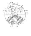
- FIG. 3 is a cross-sectional view corresponding to the line A1-A1 of FIG.
- the distal end portion 10 a includes a distal end portion of the treatment instrument channel 104 through which the treatment instrument 14 is inserted, an illumination section 105, an imaging section 106, and an air / water supply port 107.
- . 4 is a cross-sectional view corresponding to the line B1-B1 of FIG.
- the distal end portion 10 a includes a screw 108.
- 2 is a cross section corresponding to the line C1-C1 in FIGS. Further, in the present specification, “upper” described below means the upper part of the drawing as shown in FIG. 2, and “lower” means the lower part of the drawing as shown in FIG. To do.
- the tip hard portion 101 is made of a hard member such as various metals or hard resin.
- the distal end rigid portion 101 is formed with an opening 101 a for accommodating the distal end portion of the treatment instrument channel 104.
- the ultrasonic transducer unit 102 includes an ultrasonic transducer that transmits ultrasonic waves and receives ultrasonic waves (ultrasonic echoes) reflected from the observation target.
- the observation direction of the ultrasonic transducer section 102 is a predetermined range on the side of the insertion section 10 (above the paper surface of FIG. 2).
- the observation direction of the ultrasonic transducer section 102 can be changed by the bending operation of the bending section 10b.
- a signal cable 103 that is electrically connected to the ultrasonic observation apparatus 4 via the universal cord 12 and the ultrasonic cable 8 is connected to the ultrasonic transducer unit 102.
- the treatment instrument channel 104 has a tubular shape, and causes the treatment instrument 14 inserted from the treatment instrument insertion port 11b of the operation section 11 to protrude from the distal end portion 10a of the insertion section 10.
- the treatment instrument channel 104 in an initial state before the treatment instrument 14 described below is raised is accommodated in the opening 101 a in a cross section orthogonal to the insertion direction. If there is a portion where the treatment instrument channel 104 protrudes from the opening 101a, the protrusion of the treatment instrument channel 104 may interfere with the insertion of the insertion section 10 when the insertion section 10 is inserted into the subject. It is.
- a gap G is provided between the distal end hard portion 101 and the treatment instrument channel 104.
- the gap G is preferably 0.1 mm or more and 3 mm or less, for example.
- the illumination unit 105 irradiates the observation target (the surface of an organ or the like) with illumination light from the light source device 6.
- the imaging unit 106 includes an optical system that collects reflected light reflected on the surface of an observation target such as an organ, and an imaging device that performs O / E conversion on the collected light and outputs the electrical signal.
- the observation direction of the imaging unit 106 is an oblique direction of the insertion unit 10 (upper left in FIG. 2).
- the observation direction of the imaging unit 106 can be changed by the bending operation of the bending unit 10b.
- the air / water supply port 107 supplies or supplies gas or liquid into the subject.
- the screw 108 is screwed into the screw hole of the distal end hard portion 101 to fix the treatment instrument channel 104 in the distal end hard portion 101. Further, the screw hole is sealed with an adhesive or the like so that water tightness is maintained.
- the distal end portion of the treatment instrument channel 104 includes a treatment instrument insertion passage 104a communicating with the treatment instrument insertion port 11b of the operation section 11, and a distal end disposed on the outer periphery of the distal end of the treatment instrument insertion passage 104a.
- the treatment instrument insertion passage 104a is a flexible tubular member made of resin or the like.
- the treatment instrument 14 inserted from the treatment instrument insertion port 11b of the operation unit 11 can be inserted into the treatment instrument insertion path 104a, and the treatment instrument 14 is protruded from the opening of the distal end hard portion 101.
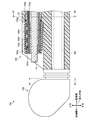
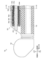
- FIG. 5 is a view for explaining the structure of the tip bending portion of FIG.
- FIG. 5 shows a state in which the treatment instrument 14 and the treatment instrument insertion path 104a are removed from FIG.
- the tip bending portion 104b has a node ring structure in which a ring-shaped member 104ba is caulked with a pin 104bb so as to be rotatably connected.
- the ring-shaped member 104ba becomes narrower in the upper direction above the pin 104bb.
- a gap 104bc whose width becomes narrower downward is formed in the distal end bending portion 104b.
- the ring-shaped member 104ba has a constant width below the pin 104bb. As a result, a gap 104bd having a constant width is formed in the tip bending portion 104b. Further, the ring-shaped member 104ba encloses the treatment instrument insertion passage 104a having a circular cross section in the cross section of FIG. 4 (cross section orthogonal to the insertion direction) and the wire 104d disposed only above the treatment instrument insertion passage 104a. In this cross section, an elliptical cross section having a major axis in the vertical direction is formed.
- the ring-shaped member 104ba and the pin 104bb are members made of metal such as stainless steel.
- the tip member 104c is an annular member made of, for example, resin or various metals, and is bonded to the treatment instrument insertion path 104a.
- One end of the wire 104d is fixed to the tip member 104c by adhesion, brazing, or the like, and the other end is connected to operation means such as a lever of the operation unit 11.
- the wire 104d can be moved along the insertion direction when a user such as a doctor raises the operation means.
- the blade 104e is a cylindrical member knitted with metal, and is disposed on the outer periphery of the tip bending portion 104b.
- the blade 104e prevents the curved rubber 104f from being sandwiched between the ring-shaped members 104ba of the distal bending portion 104b or the like when performing the raising operation of the distal end portion of the treatment instrument channel 104 described later.
- the curved rubber 104f is provided so as to cover the outer periphery of the distal bending portion 104b, and is bonded to the proximal end portion of the distal bending portion 104b on the proximal end side and the distal end member 104c on the distal end side. As a result, the curved rubber 104f covers the distal curved portion 104b and the wire 104d and keeps them watertight.
- the O-ring 104g is made of an elastic member such as silicon, and is fitted in a groove formed at the base end portion of the distal end bending portion 104b, and seals between the distal end hard portion 101 and the distal end bending portion 104b in a watertight manner.
- the operation of the distal end portion of the treatment instrument channel 104 will be described.
- the tip member 104c and the ring-shaped member 104ba of the tip bending portion 104b are interlocked with the wire 104d.
- the upper part moves to the proximal side.
- the ring-shaped member 104ba of the tip bending portion 104b rotates around the pin 104bb.
- FIG. 6 is a schematic partial sectional view showing a state where the distal end portion of the treatment instrument channel of FIG. 2 raises the treatment instrument.
- the broken line represents the initial state of the distal end portion of the treatment instrument channel 104.
- the ring-shaped member 104ba of the tip bending portion 104b rotates, the width of the gap 104bc at the top of the tip bending portion 104b is narrowed, and the width of the gap 104bd at the bottom of the tip bending portion 104b is widened.
- the bending portion 104b is bent upward.
- the treatment instrument insertion path 104a and the bending rubber 104f having flexibility together with the distal bending portion 104b are bent in conjunction with the distal bending portion 104b, and the entire distal end portion of the treatment instrument channel 104 is bent.
- the treatment instrument 14 inserted through the treatment instrument channel 104 is raised in conjunction with the operation of the distal end portion of the treatment instrument channel 104.
- the observation directions of the imaging unit 106 and the ultrasonic transducer unit 102 are maintained. Therefore, the ultrasonic endoscope 2 can independently change the direction in which the treatment instrument 14 projects from the treatment instrument channel 104 (projection direction) and the observation direction of the imaging unit 106 and the ultrasonic transducer unit 102. it can.
- the movable portion having a complicated configuration such as the distal end bending portion 104 b having the function of raising the treatment instrument 14 and the wire 104 d is watertightly covered with the bending rubber 104 f. That is, the distal end portion of the treatment instrument channel 104 is configured to be watertight and bendable.
- the ultrasonic endoscope 2 does not have a complicated configuration in a portion that needs to be cleaned that is not kept watertight, and has good cleaning efficiency. Therefore, the ultrasonic endoscope 2 according to the first embodiment is an endoscope with good cleaning efficiency.
- the gap G is provided between the distal end hard portion 101 and the treatment instrument channel 104, so that the periphery of the distal end portion of the treatment instrument channel 104 is provided. It can be cleaned directly with a brush and the cleaning efficiency is good.
- interval G has a width
- the gap G is not too wide from the viewpoint of miniaturization of the distal end portion 10a. From these requests, the gap G is set to 0.1 mm or more and 3 mm or less.
- the treatment instrument channel 104 of the ultrasonic endoscope 2 has one wire 104d only above the distal end bending portion 104b.
- the tip bending portion 104b has an elliptical cross section, and the tip bending portion 104b can be made thinner than a structure having a plurality of wires to be described later.
- the wire 104d may be formed only on the lower side.
- a treatment instrument raising base of an endoscope is configured to perform a raising operation with a single wire, and has, for example, an operation lever as an operation means for raising the wire. Since the ultrasound endoscope 2 performs the raising operation of the distal end portion of the treatment instrument channel 104 with one wire 104d, an operation lever having a conventional configuration can be used as it is.
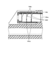
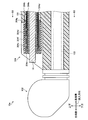
- FIG. 7 is a view for explaining another structure of the distal end bending portion of FIG.
- FIG. 7 shows a state in which the treatment instrument 14 and the treatment instrument insertion path 104a are removed from FIG.
- the distal end bending portion 104b includes a tubular member 104be that is a pipe made of, for example, a superelastic alloy.
- the tubular member 104be is formed with a gap 104bc and a gap 104bd as slits for reducing the power required for the bending operation input to the operation unit 11.
- the distal end bending portion 104b is configured by a single member connected by a connecting portion 104bf.
- the width of the gap 104bc becomes narrower downward above the connecting portion 104bf, and the width of the gap 104bd is constant below the connecting portion 104bf.
- the tubular member 104be is bent around the connecting portion 104bf, the width of the gap 104bc above the tubular member 104be is narrowed, and the gap 104bd below the tubular member 104be.
- the distal end bending portion 104b bends upward.
- the raising operation is also possible using the tip bending portion 104b having such a configuration.
- tip bending part 104b can be comprised with one member, manufacturing cost can be reduced by simplification of a process.
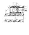
- FIG. 8 is a schematic diagram illustrating a configuration of a main part of an ultrasonic diagnostic system including the ultrasonic endoscope according to the second embodiment of the present invention. Since the ultrasonic endoscope according to the second embodiment is the same as the ultrasonic endoscope 2 according to the first embodiment except for the configuration of the distal end portion of the treatment instrument channel 204, description thereof will be omitted as appropriate.
- the distal end portion of the treatment instrument channel 204 includes a treatment instrument insertion path 204a communicating with the treatment instrument insertion port 11b of the operation section 11, a distal end bending portion 204b disposed on the outer periphery of the distal end of the treatment instrument insertion path 204a, and a treatment instrument.
- a distal end member 204c disposed at the distal end of the insertion path 204a in the insertion direction, a wire 204d disposed along the insertion direction and connected to the distal end member 204c, and the distal bending portion 204b and the wire 204d via the blade 204e.
- a curved rubber 204f as an exterior portion that covers the water tightly, and an O-ring 204g that tightly seals between the distal end hard portion 101 and the distal curved portion 204b.
- FIG. 9 is a cross-sectional view corresponding to line B2-B2 of FIG. 8 is a cross section corresponding to the line C2-C2 in FIG.
- the wire 204d has two wires arranged one above the other on the top and bottom curved portions 204b.
- the treatment instrument channel 204 of the second embodiment operates more smoothly than the treatment instrument channel 104 of the ultrasonic endoscope 2 according to the first embodiment having one wire.
- the direction in which the treatment instrument 14 projects from the treatment instrument channel 204 (projection direction) and the observation direction of the imaging unit 106 and the ultrasonic transducer unit 102 are independent. Can be changed.
- the wire 204d is suitable for transmitting a pulling operation rather than a pushing operation, in the ultrasonic endoscope according to the second embodiment, the wire is more particularly inverted than a single ultrasonic endoscope. The operation can be performed smoothly.
- the upper wire 204d and the lower wire 204d may be linked to each other, or may be movable independently of each other.
- the distal end bending portion 204b having the function of raising the treatment instrument 14, the wire 204d, and the like are watertightly covered with the bending rubber 204f. That is, the distal end portion of the treatment instrument channel 204 is configured to be watertight and bendable.
- the ultrasonic endoscope according to the second embodiment does not have a complicated configuration in a portion that requires cleaning that is not kept watertight, and has good cleaning efficiency. Therefore, the ultrasonic endoscope according to the second embodiment is an endoscope with good cleaning efficiency.
- FIG. 10 is a schematic diagram illustrating a configuration of a main part of an ultrasonic diagnostic system including the ultrasonic endoscope according to the third embodiment of the present invention. Since the ultrasonic endoscope according to the third embodiment is the same as the ultrasonic endoscope 2 according to the first embodiment except for the configuration of the distal end portion of the treatment instrument channel 304, description thereof will be omitted as appropriate.
- the distal end portion of the treatment instrument channel 304 includes a treatment instrument insertion passage 304a that communicates with the treatment instrument insertion port 11b of the operation section 11, a distal bending portion 304b that is disposed on the outer periphery of the distal end of the treatment instrument insertion passage 304a, and a treatment instrument.
- a distal end member 304c disposed at the distal end of the insertion path 304a in the insertion direction, a wire 304d disposed along the insertion direction and connected to the distal end member 304c, and the distal bending portion 304b and the wire 304d via the blade 304e.
- Curved rubber 304f as an exterior portion that covers the water tightly, and an O-ring 304g that tightly seals the space between the distal end hard portion 101 and the distal curved portion 304b.
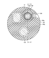
- FIG. 11 is a cross-sectional view corresponding to line B3-B3 in FIG.
- the cross section in FIG. 10 is a cross section corresponding to the line C3-C3 in FIG.
- the wire 304d has four wires arranged one by one on the top, bottom, left, and right of the distal end bending portion 304b.
- FIG. 12 is a view for explaining the structure of the tip bending portion of FIG. FIG. 12 shows a state in which the treatment instrument 14 and the treatment instrument insertion path 304a are removed from FIG.
- the tubular member 304ba is integrally formed by being connected by a connecting portion 304bb in the horizontal direction (the front-rear direction in FIG. 12) and a connecting portion 304bc in the vertical direction.
- the tubular member 304ba has a gap 304bd whose width becomes narrower downward above the connecting part 304bb and a gap 304be whose width is constant below the connecting part 304bb.
- the tubular member 304ba has a gap 304bf that decreases in width toward the connecting portion 304bc.
- the distal end portion of the treatment instrument channel 304 can raise the treatment instrument 14 with the upper and lower wires 304d and can move the treatment instrument 14 to the left and right with the left and right wires 304d. Therefore, the ultrasonic endoscope according to the third embodiment can change the protruding direction of the treatment instrument 14 independently of the observation direction of the endoscope.
- the ultrasonic endoscope according to the third embodiment adjusts the left and right positions of the treatment instrument 14 when, for example, a puncture needle is inserted into the treatment instrument channel 304 to puncture a region of interest of the subject. It has a function that cannot be obtained with a conventional treatment instrument elevator.
- the distal end bending portion 304b having a function of raising the treatment instrument 14, the wire 304d, and the like are watertightly covered with the bending rubber 304f. That is, the distal end portion of the treatment instrument channel 304 is configured to be watertight and bendable.
- the ultrasonic endoscope according to the third embodiment does not have a complicated configuration in a portion that is not kept watertight and requires cleaning, and has high cleaning efficiency. Therefore, the ultrasonic endoscope according to the third embodiment is an endoscope with good cleaning efficiency.
- the tip bending portion of the present invention is not particularly limited as long as it is a bendable structure.
- a nodal ring structure as shown in FIG. 5 may be used as the distal bending portion 304b.
- the perspective type endoscope in which the observation direction of the imaging unit is oblique has been described, but the present invention is not limited to this.
- a direct-view type endoscope that observes a direction along the insertion direction or a side-view type endoscope that observes a direction orthogonal to the insertion direction may be used.
- the protruding direction of the treatment tool 14 can be changed independently of the observation direction of the endoscope by applying the configuration of the above embodiment.
Abstract
内視鏡は、被検体内に挿入される挿入部と、前記挿入部の基端側に連設された操作部と、前記挿入部の先端に配設され、前記被検体を観察する観察手段と、前記被検体に対して処置を施す処置具を挿通し、前記挿入部の先端部から突出させる処置具挿通路と、前記処置具挿通路の先端に配設され、前記操作部の起上操作に応じて湾曲し、前記処置具を起上させる先端湾曲部と、前記先端湾曲部を覆うように設けられた外装部と、を備える。これにより、洗浄効率が良好な内視鏡を提供する。
Description
本発明は、内視鏡に関する。
従来、被検体の体内に挿入されて被検部位の観察等を行う内視鏡が知られており、医療分野等で広く利用されている。近年の内視鏡には、被検体内の処置を行なう穿刺針等の処置具を患部へ向けて送り出すための処置具起上台を備えたものがある。例えば、特許文献1には、平板状の部材を回動可能に順次接続した多関節構造の処置具起上台と、処置具起上台の先端に接続された起上操作用のワイヤと、を備える内視鏡が開示されている。この内視鏡では、医師等のユーザの起上操作によりワイヤが基端側に引っ張られることによって、処置具起上台の平板状の部材が順次回動し、処置具を起上させる。
しかしながら、上述した従来の処置具起上台を有する内視鏡では、平板状の部材の接続部やワイヤの接続部などが複雑な構成を有するために洗浄効率が悪いという課題があった。
本発明は、上記に鑑みてなされたものであって、洗浄効率が良好な内視鏡を提供することを目的とする。
上述した課題を解決し、目的を達成するために、本発明の一態様に係る内視鏡は、被検体内に挿入される挿入部と、前記挿入部の基端側に連設された操作部と、前記挿入部の先端に配設され、前記被検体を観察する観察手段と、前記被検体に対して処置を施す処置具を挿通し、前記挿入部の先端部から突出させる処置具挿通路と、前記処置具挿通路の先端に配設され、前記操作部の起上操作に応じて湾曲し、前記処置具を起上させる先端湾曲部と、前記先端湾曲部を覆うように設けられた外装部と、を備えることを特徴とする。
また、本発明の一態様に係る内視鏡は、前記先端湾曲部は、前記操作部の前記起上操作に応じて前記処置具が突出する方向を前記観察手段が観察する方向とは独立して変更することを特徴とする。
また、本発明の一態様に係る内視鏡は、前記挿入部が伸びる方向に沿って配設されるとともに前記操作部に接続される1本のワイヤを備え、前記ワイヤの先端部は、前記外装部で覆われていることを特徴とする。
また、本発明の一態様に係る内視鏡は、前記先端湾曲部は、前記挿入部が伸びる方向と直交する断面が楕円形をなすことを特徴とする。
また、本発明の一態様に係る内視鏡は、前記挿入部が伸びる方向に沿ってそれぞれ配設された2本のワイヤを備えることを特徴とする。
また、本発明の一態様に係る内視鏡は、前記挿入部が伸びる方向に沿ってそれぞれ配設された4本のワイヤを備えることを特徴とする。
また、本発明の一態様に係る内視鏡は、前記先端湾曲部は、前記湾曲動作に必要な動力を低減するスリットが形成された超弾性合金からなるパイプを有することを特徴とする。
また、本発明の一態様に係る内視鏡は、前記挿入部の先端側に配設され、開口部が形成された先端硬質部を備え、前記挿入部が伸びる方向と直交する断面において、前記湾曲していない初期状態の前記先端湾曲部が前記開口部内に収まることを特徴とする。
また、本発明の一態様に係る内視鏡は、前記観察手段は、観察対象で反射した光を集光する光学系と集光した光を変換して電気信号を出力する撮像素子とを有する撮像部、又は、観察対象で反射した超音波を受信して電気信号を出力する超音波振動子部を含むことを特徴とする。
本発明によれば、洗浄効率が良好な内視鏡を実現することができる。
以下に、図面を参照して本発明に係る内視鏡の実施の形態を説明する。なお、これらの実施の形態により本発明が限定されるものではない。以下の実施の形態においては、観察対象を超音波で観察する超音波振動子を有する超音波内視鏡を例示して説明するが、本発明は、被検体内の処置を行なうための穿刺針等の処置具を用いる内視鏡一般に適用することができる。
また、図面の記載において、同一又は対応する要素には適宜同一の符号を付している。また、図面は模式的なものであり、各要素の寸法の関係、各要素の比率などは、現実と異なる場合があることに留意する必要がある。図面の相互間においても、互いの寸法の関係や比率が異なる部分が含まれている場合がある。
(実施の形態1)
図1は、本発明の実施の形態1に係る超音波内視鏡を備えた超音波診断システムの構成を示す模式図である。図1に示す超音波診断システム1は、超音波内視鏡2と、内視鏡観察装置3と、超音波観察装置4と、表示装置5と、光源装置6と、超音波内視鏡2と内視鏡観察装置3を接続するビデオケーブル7と、超音波内視鏡2と超音波観察装置4とを接続する超音波ケーブル8と、超音波内視鏡2と光源装置6とを接続する光源ケーブル9と、を備える。
図1は、本発明の実施の形態1に係る超音波内視鏡を備えた超音波診断システムの構成を示す模式図である。図1に示す超音波診断システム1は、超音波内視鏡2と、内視鏡観察装置3と、超音波観察装置4と、表示装置5と、光源装置6と、超音波内視鏡2と内視鏡観察装置3を接続するビデオケーブル7と、超音波内視鏡2と超音波観察装置4とを接続する超音波ケーブル8と、超音波内視鏡2と光源装置6とを接続する光源ケーブル9と、を備える。
超音波内視鏡2は、観察対象を観察する観察手段として、観察対象で反射した光を集光する光学系と集光した光を変換して電気信号を出力する撮像素子とを有する撮像部と、観察対象で反射した超音波を受信して電気信号を出力する超音波振動子部と、を有する内視鏡である。内視鏡観察装置3は、内視鏡観察機能を制御するとともに、内視鏡観察により超音波内視鏡2から出力された出力信号を処理する。超音波観察装置4は、超音波観察機能を制御するとともに、超音波観察により超音波内視鏡2から出力された出力信号を処理する。表示装置5は、例えば内視鏡観察装置3及び超音波観察装置4から出力された信号を取得し、内視鏡画像と超音波断層像とのうちの少なくとも一方を適宜表示する。光源装置6は、内視鏡観察を行うための照明光を供給するための光源を備えている。
超音波内視鏡2は、先端に観察手段が配設され、被検体内に挿入される挿入部10と、この挿入部10の基端側に連設された操作部11と、この操作部11の側部から延出するユニバーサルコード12と、ユニバーサルコード12に連設され、ビデオケーブル7、超音波ケーブル8、及び光源ケーブル9とそれぞれ接続されるコネクタ部13と、を備える。なお、本明細書において、図1に示すように、挿入部10を挿入する方向を「挿入方向」とし、以下に記載する「先端側」は、挿入方向における先端側を意味し、「基端側」は、挿入方向における先端側と反対側(操作部11側)を意味する。
挿入部10は、先端側から順に、先端部10aと、操作部11に設けた湾曲ノブ11aの回転操作に応じて湾曲自在に構成された湾曲部10bと、可撓性を有する可撓管部10cと、を有する。可撓管部10cの基端は、操作部11の先端側に連設されている。先端部10aには、後述する処置具の先端を突出させるための処置具チャンネルの先端部が配設される。
操作部11は、湾曲ノブ11aを有する。さらに、操作部11には、被検体に対して処置を施す処置具である穿刺針等を被検体内へと導入するための処置具挿入口11bが設けられている。挿入部10の内部には後述する処置具挿通路が設けられており、処置具挿入口11bは、処置具挿通路の挿入口になっている。
超音波内視鏡2と内視鏡観察装置3とは、コネクタ部13に接続されるビデオケーブル7によって電気的に接続される。超音波内視鏡2と超音波観察装置4とは、コネクタ部13に接続される超音波ケーブル8によって電気的に接続される。光源ケーブル9は光ファイバーケーブルである。超音波内視鏡2と光源装置6とは、コネクタ部13に接続される光源ケーブル9によって光源装置6の光源からの照明光を超音波内視鏡2に導く。
図2は、図1に示す超音波内視鏡の先端硬質部の模式的な部分断面図である。先端部10aは、挿入部10の先端側に位置する先端硬質部101と、先端硬質部101の先端に配設された超音波振動子部102と、超音波振動子部102の基端側に接続された信号ケーブル103と、を備える。
図3は、図2のA1-A1線に対応する断面図である。図2、図3に示すように、先端部10aは、処置具14が挿通される処置具チャンネル104の先端部と、照明部105と、撮像部106と、送気送水口107と、を備える。図4は、図2のB1-B1線に対応する断面図である。図4に示すように、先端部10aは、ネジ108を備える。なお、図2の断面は、図3、図4のC1-C1線に対応する断面である。また、本明細書において、以下に記載する「上方」は、図2に記載するような各図の紙面上方を意味し、「下方」は図2に記載するような各図の紙面下方を意味する。
先端硬質部101は、各種金属、硬質な樹脂等の硬質部材からなる。先端硬質部101には、処置具チャンネル104の先端部を収容する開口部101aが形成されている。
超音波振動子部102は、超音波を送信するとともに観察対象において反射された超音波(超音波エコー)を受信する超音波振動子を有する。超音波振動子部102の観察方向は、挿入部10の側方(図2の紙面上方)の所定の範囲である。この超音波振動子部102の観察方向は、湾曲部10bの湾曲動作によって変更可能である。また、超音波振動子部102には、ユニバーサルコード12及び超音波ケーブル8を介して超音波観察装置4に電気的に接続する信号ケーブル103が接続されている。
処置具チャンネル104は、管状をなし、操作部11の処置具挿入口11bから挿入された処置具14を挿入部10の先端部10aから突出させる。図3からわかるように挿入方向と直交する断面において、後述する処置具14を起上状態とする前の初期状態の処置具チャンネル104が開口部101a内に収まることが好ましい。処置具チャンネル104が開口部101aから突出している部分があると、挿入部10が被検体内に挿入される際に、処置具チャンネル104の突出部が挿入部10の挿入を妨げる場合があるからである。また、図3からわかるように、先端硬質部101と処置具チャンネル104との間には隙間Gが設けられている。隙間Gは、例えば0.1mm以上3mm以下であることが好ましい。
照明部105は光源装置6からの照明光を観察対象(臓器等の表面)に照射する。撮像部106は、臓器等の観察対象の表面において反射された反射光を集光する光学系と、集光した光をO/E変換して電気信号として出力する撮像素子と、を有する。撮像部106の観察方向は、挿入部10の斜方(図2の紙面左上)である。この撮像部106の観察方向は、湾曲部10bの湾曲動作によって変更可能である。
送気送水口107は被検体内へ気体又は液体を送気又は送水する。ネジ108は、図4に示すように、先端硬質部101のネジ穴に螺合されて、処置具チャンネル104を先端硬質部101内に固定する。また、ネジ穴は、接着剤等によって水密が保たれるように封止される。
次に、処置具チャンネル104の先端部の構成について詳細に説明する。図2に示すように、処置具チャンネル104の先端部は、操作部11の処置具挿入口11bに連通する処置具挿通路104aと、処置具挿通路104aの先端の外周に配設された先端湾曲部104bと、処置具挿通路104aの先端に配設される先端部材104cと、挿入方向に沿って配設され、先端部材104cに接続されるワイヤ104dと、ブレード104eを介して先端湾曲部104b及びワイヤ104dを覆う外装部としての湾曲ゴム104fと、先端硬質部101と先端湾曲部104bとの間を封止するOリング104gと、を備える。
処置具挿通路104aは、樹脂等からなる可撓性を有する管状部材である。処置具挿通路104aには、操作部11の処置具挿入口11bから挿入された処置具14を挿通可能であり、処置具14を先端硬質部101の開口部から突出させる。
図5は、図2の先端湾曲部の構造を説明するための図である。また、図5は、図2から処置具14と処置具挿通路104aとを取り除いた状態を表す。図2、図5を参照して、先端湾曲部104bの構成について詳細に説明する。先端湾曲部104bは、輪状部材104baをピン104bbでかしめて回転可能に連結した節輪構造を有する。輪状部材104baは、ピン104bbより上方において上方に向かって幅が狭くなる。その結果、先端湾曲部104bには、下方に向かって幅が狭くなる隙間104bcが形成されている。一方、輪状部材104baは、ピン104bbより下方において幅が一定である。その結果、先端湾曲部104bには、幅が一定の隙間104bdが形成されている。また、輪状部材104baは、図4の断面(挿入方向と直交する断面)において円形断面を有する処置具挿通路104aと処置具挿通路104aの上方のみに配設されたワイヤ104dとを内包するため、この断面において上下方向に長軸を有する楕円形の断面をなす。輪状部材104ba及びピン104bbは、例えばステンレス等の金属からなる部材である。
先端部材104cは、例えば樹脂や各種金属からなる環状部材であって、処置具挿通路104aに接着される。
ワイヤ104dは、一端が先端部材104cに接着、ろう付け等で固着され、他端が操作部11のレバー等の操作手段に接続される。そして、ワイヤ104dは、医師等のユーザが操作手段を起上操作することにより挿入方向に沿って移動可能である。
ブレード104eは、金属を編み込んだ筒状部材であり、先端湾曲部104bの外周に配設される。ブレード104eは、後述する処置具チャンネル104の先端部の起上動作を行う際に、湾曲ゴム104fが先端湾曲部104bの輪状部材104baの間等に挟まれることを防止する。
湾曲ゴム104fは、先端湾曲部104bの外周を覆うように設けられ、基端側で先端湾曲部104bの基端部と、先端側で先端部材104cとそれぞれ接着される。その結果、湾曲ゴム104fは、先端湾曲部104bとワイヤ104dとを覆いこれらを水密に保つ。
Oリング104gは、シリコン等の弾性部材からなり、先端湾曲部104bの基端部に形成された溝に嵌装され、先端硬質部101と先端湾曲部104bとの間を水密に封止する。
次に、処置具チャンネル104の先端部の動作について説明する。まず、図2の初期状態において、操作部11の操作手段の起上操作によりワイヤ104dが基端側に引っ張られると、ワイヤ104dに連動して先端部材104c及び先端湾曲部104bの輪状部材104baの上部が基端側に移動する。すると、先端湾曲部104bの輪状部材104baは、ピン104bbを中心に回転する。
図6は、図2の処置具チャンネルの先端部が処置具を起上した様子を表す模式的な部分断面図である。図6において、破線は処置具チャンネル104の先端部の初期状態を表している。図6に示すように、先端湾曲部104bの輪状部材104baが回転すると、先端湾曲部104bの上部の隙間104bcの幅が狭められるとともに、先端湾曲部104bの下部の隙間104bdの幅が広がり、先端湾曲部104bが上方に湾曲する。すると、先端湾曲部104bとともに可撓性を有する処置具挿通路104a及び湾曲ゴム104f等が先端湾曲部104bに連動して湾曲し、処置具チャンネル104の先端部全体が湾曲する。そして、処置具チャンネル104の先端部の動作に連動して処置具チャンネル104に挿通された処置具14が起上される。このとき、撮像部106及び超音波振動子部102の観察方向は維持されている。従って、超音波内視鏡2は、処置具14が処置具チャンネル104から突出する方向(突出方向)と、撮像部106及び超音波振動子部102の観察方向とを独立して変更することができる。
ここで、超音波内視鏡2では、処置具14を起上させる機能を有する先端湾曲部104b及びワイヤ104d等の複雑な構成を有する可動部が湾曲ゴム104fによって水密に外装されている。すなわち、処置具チャンネル104の先端部は、水密に外装され、かつ湾曲可能な構成である。その結果、超音波内視鏡2は、水密に保たれていない洗浄が必要となる部分に複雑な構成を有さず、洗浄効率が良好である。従って、本実施の形態1に係る超音波内視鏡2は、洗浄効率が良好な内視鏡である。
また、超音波内視鏡2では、図3に示すように、先端硬質部101と処置具チャンネル104との間に隙間Gが設けられていることにより、処置具チャンネル104の先端部の周囲をブラシで直接洗浄することができ、さらに洗浄効率が良好である。なお、隙間Gは、洗浄効率の観点から、少なくともブラシの毛が入る程度の幅を有することが好ましい。一方で隙間Gは、先端部10aの小型化の観点から幅が広すぎないことが好ましい。これらの要請から、隙間Gは、0.1mm以上3mm以下とされている。
また、実施の形態1に係る超音波内視鏡2の処置具チャンネル104は、先端湾曲部104bの上方のみに1本のワイヤ104dを有する。その結果、図4に示すように、先端湾曲部104bは、楕円形の断面を有し、後述する複数のワイヤを有する構造に比べて先端湾曲部104bを細径化することができ、先端部10aの小型化に有利な構成である。なお、ワイヤ104dは、下方にのみ形成される構成であってもよい。また、従来、内視鏡の処置具起上台は1本のワイヤで起上動作を行う構成であり、このワイヤを起上操作するための操作手段として例えば操作レバーを有する。超音波内視鏡2では、1本のワイヤ104dで処置具チャンネル104の先端部の起上操作を行うため、従来の構成の操作レバーをそのまま利用することができる。
また、先端湾曲部104bの構成は、図5に示す節輪構造に限られない。図7は、図2の先端湾曲部の他の構造を説明するための図である。図7は、図5と同様に図2から処置具14と処置具挿通路104aとを取り除いた状態を表す。この先端湾曲部104bは、たとえば超弾性合金からなるパイプである管状部材104beを有する。そして、管状部材104beには、操作部11に入力する湾曲動作に必要な動力を低減するスリットとして、隙間104bcと隙間104bdとが形成されている。また、先端湾曲部104bは、連結部104bfにより連結された1つの部材で構成されている。
隙間104bcは、連結部104bfより上方において下方に向かって幅が狭くなり、隙間104bdは、連結部104bfより下方において幅が一定である。このとき、ワイヤ104dが基端側に引っ張られると、連結部104bfを中心に管状部材104beが湾曲し、管状部材104beの上方の隙間104bcの幅が狭められるとともに、管状部材104beの下方の隙間104bdの幅が広がり、先端湾曲部104bが上方に湾曲する。このような構成の先端湾曲部104bを用いても起上動作が可能である。なお、この構成では、先端湾曲部104bを1つの部材で構成することができるため、工程の簡易化により製造コストを削減することができる。
(実施の形態2)
次に、本発明の実施の形態2について説明する。図8は、本発明の実施の形態2に係る超音波内視鏡を備えた超音波診断システムの要部の構成を示す模式図である。実施の形態2に係る超音波内視鏡は、処置具チャンネル204の先端部の構成以外は実施の形態1に係る超音波内視鏡2と同一であるので適宜説明を省略する。
次に、本発明の実施の形態2について説明する。図8は、本発明の実施の形態2に係る超音波内視鏡を備えた超音波診断システムの要部の構成を示す模式図である。実施の形態2に係る超音波内視鏡は、処置具チャンネル204の先端部の構成以外は実施の形態1に係る超音波内視鏡2と同一であるので適宜説明を省略する。
処置具チャンネル204の先端部は、操作部11の処置具挿入口11bに連通する処置具挿通路204aと、処置具挿通路204aの先端の外周に配設された先端湾曲部204bと、処置具挿通路204aの挿入方向の先端に配設される先端部材204cと、挿入方向に沿って配設され、先端部材204cに接続されるワイヤ204dと、ブレード204eを介して先端湾曲部204b及びワイヤ204dを水密に覆う外装部としての湾曲ゴム204fと、先端硬質部101と先端湾曲部204bとの間を水密に封止するOリング204gと、を有する。
図9は、図8のB2-B2線に対応する断面図である。図8の断面は、図9のC2-C2線に対応する断面である。図9に示すように、ワイヤ204dは、先端湾曲部204bの上下にそれぞれ1本ずつ配設された2本のワイヤを有する。そして、処置具チャンネル204の先端部を起上する際に、上方のワイヤ204dを基端側に引っ張るとともに連動して下方のワイヤ204dを先端側に押し出す。そのため、実施の形態2の処置具チャンネル204は、ワイヤが1本の実施の形態1に係る超音波内視鏡2の処置具チャンネル104よりも動作がスムーズである。従って、実施の形態2に係る超音波内視鏡は、処置具14が処置具チャンネル204から突出する方向(突出方向)と、撮像部106及び超音波振動子部102の観察方向とを独立して変更することができる。
なお、処置具チャンネル204を起上状態から初期状態に倒置するには、下方のワイヤ204dを基端側に引っ張るとともに連動して上方のワイヤ204dを先端側に押し出せばよい。ここで、ワイヤ204dは、押し込む操作より引っ張る操作を伝達するのに適しているため、実施の形態2に係る超音波内視鏡では、ワイヤが1本の超音波内視鏡よりも特に倒置する動作をスムーズに行うことができる。
また、上方のワイヤ204dと下方のワイヤ204dとは、連動する構成であってもよいが、互いに独立して移動可能な構成であってもよい。
ここで、実施の形態2に係る超音波内視鏡では、処置具14を起上させる機能を有する先端湾曲部204b及びワイヤ204d等が湾曲ゴム204fによって水密に外装されている。すなわち、処置具チャンネル204の先端部は、水密に外装され、かつ湾曲可能な構成である。その結果、実施の形態2に係る超音波内視鏡は、水密に保たれていない洗浄が必要となる部分に複雑な構成を有さず、洗浄効率が良好である。従って、本実施の形態2に係る超音波内視鏡は、洗浄効率が良好な内視鏡である。
(実施の形態3)
次に、本発明の実施の形態3について説明する。図10は、本発明の実施の形態3に係る超音波内視鏡を備えた超音波診断システムの要部の構成を示す模式図である。実施の形態3に係る超音波内視鏡は、処置具チャンネル304の先端部の構成以外は実施の形態1に係る超音波内視鏡2と同一であるので適宜説明を省略する。
次に、本発明の実施の形態3について説明する。図10は、本発明の実施の形態3に係る超音波内視鏡を備えた超音波診断システムの要部の構成を示す模式図である。実施の形態3に係る超音波内視鏡は、処置具チャンネル304の先端部の構成以外は実施の形態1に係る超音波内視鏡2と同一であるので適宜説明を省略する。
処置具チャンネル304の先端部は、操作部11の処置具挿入口11bに連通する処置具挿通路304aと、処置具挿通路304aの先端の外周に配設された先端湾曲部304bと、処置具挿通路304aの挿入方向の先端に配設される先端部材304cと、挿入方向に沿って配設され、先端部材304cに接続されるワイヤ304dと、ブレード304eを介して先端湾曲部304b及びワイヤ304dを水密に覆う外装部としての湾曲ゴム304fと、先端硬質部101と先端湾曲部304bとの間を水密に封止するOリング304gと、を有する。
図11は、図10のB3-B3線に対応する断面図である。図10の断面は、図11のC3-C3線に対応する断面である。図11に示すように、ワイヤ304dは、先端湾曲部304bの上下左右にそれぞれ1本ずつ配設された4本のワイヤを有する。
図12は、図10の先端湾曲部の構造を説明するための図である。図12は、図10から処置具14と処置具挿通路304aとを取り除いた状態を表す。先端湾曲部304bでは、管状部材304baが水平方向(図12の紙面前後方向)の連結部304bb及び上下方向の連結部304bcにより連結されて一体として構成されている。そして、管状部材304baは、連結部304bbより上方において下方に向かって幅が狭くなる隙間304bdと、連結部304bbより下方において幅が一定の隙間304beと、を有する。さらに、管状部材304baは、連結部304bcに向かって幅が狭くなる隙間304bfを有する。この構成により、処置具チャンネル304の先端部は、上下のワイヤ304dで処置具14の起上動作を行うとともに、左右のワイヤ304dで処置具14を左右に動かすことができる。従って、本実施の形態3に係る超音波内視鏡は、処置具14の突出方向を内視鏡の観察方向と独立して変更することができる。そして、本実施の形態3に係る超音波内視鏡は、例えば処置具チャンネル304に穿刺針を挿入して、被検体の関心部位に穿刺を行う場合に、処置具14の左右の位置を調整することができるという従来の処置具起上台では得られない機能を有する。
ここで、実施の形態3に係る超音波内視鏡では、処置具14を起上させる機能を有する先端湾曲部304b及びワイヤ304d等が湾曲ゴム304fによって水密に外装されている。すなわち、処置具チャンネル304の先端部は、水密に外装され、かつ湾曲可能な構成である。その結果、実施の形態3に係る超音波内視鏡は、水密に保たれていない洗浄が必要となる部分に複雑な構成を有さず、洗浄効率が良好である。従って、本実施の形態3に係る超音波内視鏡は、洗浄効率が良好な内視鏡である。
なお、本発明の先端湾曲部は、湾曲可能な構造であればよく、特にその構造は限定されない。例えば、実施の形態3に係る超音波内視鏡においても、先端湾曲部304bとして図5に示すような節輪構造を用いてもよい。
また、上記実施の形態では、ワイヤの数が1本(実施の形態1)、2本(実施の形態2)、4本(実施の形態3)の例を記載したが、ワイヤの本数は特に限定されない。
また、上記実施の形態では、撮像部の観察方向が斜方である斜視型の内視鏡について説明したが、これに限られない。例えば、挿入方向に沿った方向を観察する直視型や、挿入方向に直交する方向を観察する側視型の内視鏡であってもよい。直視型又は側視型の内視鏡の場合においても、上記実施の形態の構成を適用することで、処置具14の突出方向を内視鏡の観察方向と独立して変更することができる。
さらなる効果や変形例は、当業者によって容易に導き出すことができる。よって、本発明のより広範な態様は、以上のように表わしかつ記述した特定の詳細及び代表的な実施形態に限定されるものではない。従って、添付のクレーム及びその均等物によって定義される総括的な発明の概念の精神又は範囲から逸脱することなく、様々な変更が可能である。
1 超音波診断システム
2 超音波内視鏡
3 内視鏡観察装置
4 超音波観察装置
5 表示装置
6 光源装置
7 ビデオケーブル
8 超音波ケーブル
9 光源ケーブル
10 挿入部
10a 先端部
10b 湾曲部
10c 可撓管部
11 操作部
11a 湾曲ノブ
11b 処置具挿入口
12 ユニバーサルコード
13 コネクタ部
14 処置具
101 先端硬質部
101a 開口部
102 超音波振動子部
103 信号ケーブル
104、204、304 処置具チャンネル
104a、204a、304a 処置具挿通路
104b、204b、304b 先端湾曲部
104c、204c、304c 先端部材
104d、204d、304d ワイヤ
104e、204e、304e ブレード
104f、204f、304f 湾曲ゴム
104g、204g、304g Oリング
105 照明部
106 撮像部
107 送気送水口
108 ネジ
Claims (9)
- 被検体内に挿入される挿入部と、
前記挿入部の基端側に連設された操作部と、
前記挿入部の先端に配設され、前記被検体を観察する観察手段と、
前記被検体に対して処置を施す処置具を挿通し、前記挿入部の先端部から突出させる処置具挿通路と、
前記処置具挿通路の先端に配設され、前記操作部の起上操作に応じて湾曲し、前記処置具を起上させる先端湾曲部と、
前記先端湾曲部を覆うように設けられた外装部と、
を備えることを特徴とする内視鏡。 - 前記先端湾曲部は、前記操作部の前記起上操作に応じて前記処置具が突出する方向を前記観察手段が観察する方向とは独立して変更することを特徴とする請求項1に記載の内視鏡。
- 前記挿入部が伸びる方向に沿って配設されるとともに前記操作部に接続される1本のワイヤを備え、
前記ワイヤの先端部は、前記外装部で覆われていることを特徴とする請求項1又は2に記載の内視鏡。 - 前記先端湾曲部は、前記挿入部が伸びる方向と直交する断面が楕円形をなすことを特徴とする請求項3に記載の内視鏡。
- 前記挿入部が伸びる方向に沿ってそれぞれ配設された2本のワイヤを備えることを特徴とする請求項1又は2に記載の内視鏡。
- 前記挿入部が伸びる方向に沿ってそれぞれ配設された4本のワイヤを備えることを特徴とする請求項1又は2に記載の内視鏡。
- 前記先端湾曲部は、前記湾曲動作に必要な動力を低減するスリットが形成された超弾性合金からなるパイプを有することを特徴とする請求項1~6のいずれか1つに記載の内視鏡。
- 前記挿入部の先端側に配設され、開口部が形成された先端硬質部を備え、
前記挿入部が伸びる方向と直交する断面において、前記湾曲していない初期状態の前記先端湾曲部が前記開口部内に収まることを特徴とする請求項1~7のいずれか1つに記載の内視鏡。 - 前記観察手段は、観察対象で反射した光を集光する光学系と集光した光を変換して電気信号を出力する撮像素子とを有する撮像部、又は、観察対象で反射した超音波を受信して電気信号を出力する超音波振動子部を含むことを特徴とする請求項1~8のいずれか1つに記載の内視鏡。
Priority Applications (4)
| Application Number | Priority Date | Filing Date | Title |
|---|---|---|---|
| JP2017502728A JP6104492B1 (ja) | 2015-06-18 | 2016-06-16 | 内視鏡 |
| CN201680004653.4A CN107106135B (zh) | 2015-06-18 | 2016-06-16 | 内窥镜 |
| EP16811726.5A EP3311751A4 (en) | 2015-06-18 | 2016-06-16 | ENDOSCOPE |
| US15/614,865 US10172511B2 (en) | 2015-06-18 | 2017-06-06 | Endoscope |
Applications Claiming Priority (2)
| Application Number | Priority Date | Filing Date | Title |
|---|---|---|---|
| JP2015123095 | 2015-06-18 | ||
| JP2015-123095 | 2015-06-18 |
Related Child Applications (1)
| Application Number | Title | Priority Date | Filing Date |
|---|---|---|---|
| US15/614,865 Continuation US10172511B2 (en) | 2015-06-18 | 2017-06-06 | Endoscope |
Publications (1)
| Publication Number | Publication Date |
|---|---|
| WO2016204252A1 true WO2016204252A1 (ja) | 2016-12-22 |
Family
ID=57546207
Family Applications (1)
| Application Number | Title | Priority Date | Filing Date |
|---|---|---|---|
| PCT/JP2016/068008 WO2016204252A1 (ja) | 2015-06-18 | 2016-06-16 | 内視鏡 |
Country Status (5)
| Country | Link |
|---|---|
| US (1) | US10172511B2 (ja) |
| EP (1) | EP3311751A4 (ja) |
| JP (1) | JP6104492B1 (ja) |
| CN (1) | CN107106135B (ja) |
| WO (1) | WO2016204252A1 (ja) |
Families Citing this family (3)
| Publication number | Priority date | Publication date | Assignee | Title |
|---|---|---|---|---|
| CN116369831A (zh) * | 2018-01-26 | 2023-07-04 | 富士胶片株式会社 | 内窥镜 |
| CN110384520A (zh) * | 2018-04-18 | 2019-10-29 | 深圳开立生物医疗科技股份有限公司 | 超声波成像系统及其导管 |
| CN109044248B (zh) * | 2018-06-29 | 2021-02-19 | 华南师范大学 | 基于蛇骨变向的弯曲腔体内三维光声内窥镜及其成像方法 |
Citations (4)
| Publication number | Priority date | Publication date | Assignee | Title |
|---|---|---|---|---|
| JPH05123288A (ja) * | 1991-11-06 | 1993-05-21 | Asahi Optical Co Ltd | 内視鏡の処置具起上装置 |
| JPH07184831A (ja) * | 1993-12-27 | 1995-07-25 | Olympus Optical Co Ltd | 内視鏡カバー方式の内視鏡装置 |
| JPH08215140A (ja) * | 1995-02-10 | 1996-08-27 | Olympus Optical Co Ltd | 内視鏡装置 |
| JP2008173369A (ja) * | 2007-01-22 | 2008-07-31 | Olympus Medical Systems Corp | 内視鏡用処置具 |
Family Cites Families (8)
| Publication number | Priority date | Publication date | Assignee | Title |
|---|---|---|---|---|
| GB2161389B (en) * | 1984-07-05 | 1988-06-08 | Wolf Gmbh Richard | Instrument insert for a uretero-renoscope |
| US5343853A (en) * | 1991-09-20 | 1994-09-06 | Fuji Photo Optical Co., Ltd. | Side-looking type electronic endoscope which allows manipulating tool to be inserted thereinto |
| US5460168A (en) * | 1992-12-25 | 1995-10-24 | Olympus Optical Co., Ltd. | Endoscope cover assembly and cover-system endoscope |
| JP3212788B2 (ja) * | 1993-12-27 | 2001-09-25 | オリンパス光学工業株式会社 | 内視鏡 |
| JP2000116598A (ja) | 1998-10-19 | 2000-04-25 | Toshiba Corp | 内視鏡装置 |
| US7815564B2 (en) * | 2006-02-21 | 2010-10-19 | Boston Scientific Scimed, Inc. | Positioning system for manipulating a channel within a medical device |
| US20070265494A1 (en) * | 2006-05-10 | 2007-11-15 | Boston Scientific Scimed Inc. | Flexible and retractable endoscope elevator |
| US20110112365A1 (en) * | 2009-06-03 | 2011-05-12 | Gyrus Acmi, Inc. | Endoscope shaft |
-
2016
- 2016-06-16 WO PCT/JP2016/068008 patent/WO2016204252A1/ja active Application Filing
- 2016-06-16 EP EP16811726.5A patent/EP3311751A4/en not_active Withdrawn
- 2016-06-16 CN CN201680004653.4A patent/CN107106135B/zh active Active
- 2016-06-16 JP JP2017502728A patent/JP6104492B1/ja active Active
-
2017
- 2017-06-06 US US15/614,865 patent/US10172511B2/en active Active
Patent Citations (4)
| Publication number | Priority date | Publication date | Assignee | Title |
|---|---|---|---|---|
| JPH05123288A (ja) * | 1991-11-06 | 1993-05-21 | Asahi Optical Co Ltd | 内視鏡の処置具起上装置 |
| JPH07184831A (ja) * | 1993-12-27 | 1995-07-25 | Olympus Optical Co Ltd | 内視鏡カバー方式の内視鏡装置 |
| JPH08215140A (ja) * | 1995-02-10 | 1996-08-27 | Olympus Optical Co Ltd | 内視鏡装置 |
| JP2008173369A (ja) * | 2007-01-22 | 2008-07-31 | Olympus Medical Systems Corp | 内視鏡用処置具 |
Non-Patent Citations (1)
| Title |
|---|
| See also references of EP3311751A4 * |
Also Published As
| Publication number | Publication date |
|---|---|
| US20170265718A1 (en) | 2017-09-21 |
| CN107106135B (zh) | 2020-02-28 |
| EP3311751A4 (en) | 2019-06-05 |
| US10172511B2 (en) | 2019-01-08 |
| EP3311751A1 (en) | 2018-04-25 |
| JPWO2016204252A1 (ja) | 2017-06-29 |
| JP6104492B1 (ja) | 2017-03-29 |
| CN107106135A (zh) | 2017-08-29 |
Similar Documents
| Publication | Publication Date | Title |
|---|---|---|
| US5551945A (en) | Endoscope system including endoscope and protection cover | |
| JP6249978B2 (ja) | 内視鏡 | |
| US6461304B1 (en) | Ultrasound inspection apparatus detachably connected to endoscope | |
| JP5153476B2 (ja) | 内視鏡装置 | |
| JP5489418B2 (ja) | 超音波プローブ用フード及び超音波プローブ | |
| US10485411B2 (en) | Endoscope | |
| JP6104492B1 (ja) | 内視鏡 | |
| JP4725162B2 (ja) | 超音波内視鏡 | |
| CN109069125B (zh) | 具有声波可视化能力的系统 | |
| JP2000139927A (ja) | 超音波内視鏡装置 | |
| EP3656276A1 (en) | Endoscope | |
| WO2014010283A1 (ja) | 超音波内視鏡 | |
| JP4300378B2 (ja) | 分離可能型超音波内視鏡 | |
| EP3701851A1 (en) | Endoscope | |
| EP3656281B1 (en) | Endoscope | |
| JP4441232B2 (ja) | 外付けチャンネル及びこれを備えた内視鏡装置 | |
| US20190008369A1 (en) | Endoscope | |
| JP3462597B2 (ja) | 超音波内視鏡の先端部 | |
| JP2020174748A (ja) | 超音波内視鏡 | |
| JP2018171257A (ja) | 超音波内視鏡および超音波内視鏡用フード | |
| JP2001170054A (ja) | 超音波内視鏡 | |
| JP2001087262A (ja) | 内視鏡着脱型超音波検査装置 | |
| JP2002345740A (ja) | 内視鏡 | |
| WO2018179758A1 (ja) | 超音波内視鏡 | |
| JPS647778B2 (ja) |
Legal Events
| Date | Code | Title | Description |
|---|---|---|---|
| ENP | Entry into the national phase |
Ref document number: 2017502728 Country of ref document: JP Kind code of ref document: A |
|
| 121 | Ep: the epo has been informed by wipo that ep was designated in this application |
Ref document number: 16811726 Country of ref document: EP Kind code of ref document: A1 |
|
| NENP | Non-entry into the national phase |
Ref country code: DE |
|
| WWE | Wipo information: entry into national phase |
Ref document number: 2016811726 Country of ref document: EP |