WO2016203904A1 - 伸びフランジ成形部品の製造方法 - Google Patents
伸びフランジ成形部品の製造方法 Download PDFInfo
- Publication number
- WO2016203904A1 WO2016203904A1 PCT/JP2016/065154 JP2016065154W WO2016203904A1 WO 2016203904 A1 WO2016203904 A1 WO 2016203904A1 JP 2016065154 W JP2016065154 W JP 2016065154W WO 2016203904 A1 WO2016203904 A1 WO 2016203904A1
- Authority
- WO
- WIPO (PCT)
- Prior art keywords
- outer peripheral
- peripheral edge
- concave outer
- line
- flange
- Prior art date
- Legal status (The legal status is an assumption and is not a legal conclusion. Google has not performed a legal analysis and makes no representation as to the accuracy of the status listed.)
- Ceased
Links
Images





Classifications
-
- B—PERFORMING OPERATIONS; TRANSPORTING
- B21—MECHANICAL METAL-WORKING WITHOUT ESSENTIALLY REMOVING MATERIAL; PUNCHING METAL
- B21D—WORKING OR PROCESSING OF SHEET METAL OR METAL TUBES, RODS OR PROFILES WITHOUT ESSENTIALLY REMOVING MATERIAL; PUNCHING METAL
- B21D19/00—Flanging or other edge treatment, e.g. of tubes
- B21D19/08—Flanging or other edge treatment, e.g. of tubes by single or successive action of pressing tools, e.g. vice jaws
-
- B—PERFORMING OPERATIONS; TRANSPORTING
- B21—MECHANICAL METAL-WORKING WITHOUT ESSENTIALLY REMOVING MATERIAL; PUNCHING METAL
- B21D—WORKING OR PROCESSING OF SHEET METAL OR METAL TUBES, RODS OR PROFILES WITHOUT ESSENTIALLY REMOVING MATERIAL; PUNCHING METAL
- B21D22/00—Shaping without cutting, by stamping, spinning, or deep-drawing
- B21D22/20—Deep-drawing
- B21D22/26—Deep-drawing for making peculiarly, e.g. irregularly, shaped articles
-
- B—PERFORMING OPERATIONS; TRANSPORTING
- B21—MECHANICAL METAL-WORKING WITHOUT ESSENTIALLY REMOVING MATERIAL; PUNCHING METAL
- B21D—WORKING OR PROCESSING OF SHEET METAL OR METAL TUBES, RODS OR PROFILES WITHOUT ESSENTIALLY REMOVING MATERIAL; PUNCHING METAL
- B21D53/00—Making other particular articles
- B21D53/88—Making other particular articles other parts for vehicles, e.g. cowlings, mudguards
Definitions
- the present invention has a concave outer peripheral edge that is curved so that a part of the outer peripheral edge is indented inward on the top plate, thereby manufacturing an elongated flange-molded part in which the flange is manufactured with stretch flange molding.
- stretch flange molded parts for example, press-molded parts used as body frame parts of automobiles, and parts having an L-shaped part or a T-shaped part in plan view can be exemplified.
- the present invention is a technique that is particularly suitable for production by press molding using a super high tensile material of 980 MPa or more as a raw material.
- Parts having an L-shaped part (see FIG. 11) or a T-shaped part (see FIG. 12) such as a front pillar reinforcement and a center pillar reinforcement, which are car body frame parts, are pressed from a flat metal plate.
- generally drawing or bending is employed. Drawing is usually performed using a die consisting of a punch, die, and wrinkle presser (blank holder), and the distance between the punch and die is set with the die and blank holder pressed around the metal plate. This is a method of drawing a metal plate close to it. Bending is usually performed by using a die composed of a punch, a pad, and a die, and bending is performed by relatively moving the die while the metal plate is sandwiched between the punch and the pad.
- an L-shaped part or a T-shaped part that is bent sharply is formed only by the above-described drawing, cracks and wrinkles are likely to occur.
- the strength of a metal plate that is a molding material has been increasing in order to achieve improved safety and weight reduction of an automobile body, and such a high-strength metal plate is a soft steel plate that has been conventionally used. Therefore, measures against cracks and wrinkles during press molding are important.
- the part where cracks are particularly likely to occur due to the press forming is the stretch flange forming part of the curved part. In this part, it will be in the deformation
- Patent Document 1 there is a technique described in Patent Document 1.
- a part having an L-shape when a part having an L-shape is press-molded, a vertical wall portion and a flange are formed while sliding a part of a metal material on a portion corresponding to a top plate portion in a die mold. The part is formed.
- this patent document 1 since the site
- Patent Document 1 since the metal material corresponding to a part of the top plate portion is slid, there is a place where stress is concentrated on the end surface of the metal material, and the crack of the end surface in addition to the stretch flange crack of the curved portion. Is likely to occur. For this reason, the method of Patent Document 1 is difficult to apply to a steel plate having high strength.
- the present invention has been made paying attention to such problems, and an object of the present invention is to provide a stretch flange molded part manufacturing method capable of manufacturing stretch flange molded parts manufactured with stretch flange molding while suppressing stretch flange cracking. Yes.
- a top plate portion having a concave outer peripheral portion curved so that a part of the outer peripheral portion is recessed inward, and the concave outer peripheral portion of the top plate portion.
- An elongated flange comprising a continuous vertical wall portion, and a flange portion having a concave outer peripheral edge portion that is bent toward the top plate portion side continuously to the vertical wall portion and curved so that a part of the outer peripheral edge is recessed inwardly.
- a manufacturing method for manufacturing a molded part When the concave outer peripheral edge portion of the top plate portion is defined as a first concave outer peripheral edge portion, and the concave outer peripheral edge portion of the flange portion is defined as a second concave outer peripheral edge portion, Forming the vertical wall portion after forming a step shape portion in which a ridge line extends and bends in the thickness direction so as to surround the second concave outer peripheral edge portion at a position to be the flange portion, When the contour shape of the second concave outer peripheral edge is defined by two straight portions and a concave curved portion that connects the two straight portions, it is formed by the extended lines of the two straight portions.
- the intersecting angle on the second concave outer peripheral edge side is 60 degrees or more and 90 degrees or less, Of each extension line of the two straight parts, each extension line part to the position where both extension lines intersect is used as a reference line, respectively.
- the perpendicular perpendicular bisector formed by the two reference lines is a center line
- a region located between two orthogonal lines perpendicular to the center line at a distance from the intersection with the second concave outer peripheral edge in the center line of 20 mm and 50 mm is defined as a first step forming region
- the ridge line of the step shape portion is continuous with the first ridge line extending in the direction along the second concave outer peripheral edge in the first step formation area AR1 and the end of the first ridge line, respectively. It is a manufacturing method of the stretch flange molding component characterized by being comprised from the 2nd ridgeline on either side extended along each reference line.
- a top plate portion having a concave outer peripheral edge curved so that a part of the outer peripheral edge is recessed inward, and a vertical wall portion continuous to the concave outer peripheral edge portion of the top plate portion.
- an elongated flange-molded part including a flange portion having a concave outer peripheral edge that is bent to the top plate portion side continuously to the vertical wall portion and curved so that a part of the outer peripheral edge is recessed inwardly.
- a manufacturing method comprising: When the concave outer peripheral edge portion of the top plate portion is defined as a first concave outer peripheral edge portion, and the concave outer peripheral edge portion of the flange portion is defined as a second concave outer peripheral edge portion, Forming a step-shaped portion in which a ridge line extends and bends in the thickness direction so as to surround the second concave outer peripheral edge at a position to be the flange portion;
- the contour shape of the second concave outer peripheral edge is defined by two straight portions and a concave curved portion that connects the two straight portions, it is formed by the extended lines of the two straight portions.
- the angle of intersection on the second concave outer peripheral edge side is 90 degrees or more and 120 degrees or less, Of each vertical line perpendicular to the straight line portion that is continuous from both end portions of the curved portion, each vertical line portion until the two vertical lines intersect is a line connecting both end portions of the curved portion, Each line that is folded back to the flange position is used as the reference line.
- the perpendicular perpendicular bisector formed by the two reference lines is a center line, An area located between two orthogonal lines perpendicular to the center line at distances from the intersection with the second concave outer peripheral edge of the center line at 20 mm and 50 mm is defined as a first step formation area AR1.
- the ridge lines of the step shape portion are respectively connected to the first ridge line extending in the direction along the second concave outer peripheral edge portion in the first step formation region and the end portion of the first ridge line. It is a manufacturing method of the stretch flange molding component characterized by being comprised from the 2nd ridgeline on either side extended along a reference line.
- a step-shaped portion is provided in advance so as to surround the second concave outer peripheral edge where elongation flange cracking is likely to occur.
- stretch flange cracking during bending can be suppressed.
- a pillar (refer FIG. 11) and B pillar (refer FIG. 12) are mentioned, for example. Further, in the following, description will be made by paying attention to a portion including a portion that becomes a stretch flange molded portion in a stretch flange molded part, and in each drawing, only the relevant portion is illustrated. Part 1 ". In addition, only the site
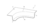
- the stretch flange molded portion 1 manufactured by the manufacturing method of the present embodiment includes a top plate portion 3 having a concave outer peripheral edge portion 3 a that is curved so that a part of the outer peripheral edge is recessed inward.
- the vertical wall portion 5 formed along the concave outer peripheral edge portion 3a of the top plate portion 3 is bent to the top plate portion 3 side continuously to the vertical wall portion 5 and a part of the outer peripheral edge is inward.
- the concave outer peripheral edge 3a of the top plate 3 is also referred to as a first concave outer peripheral edge 3a
- the concave outer peripheral edge 7a of the flange 7 is also referred to as a second concave outer peripheral edge 7a.
- the contour shape of the first concave outer peripheral edge 3a and the contour shape of the second concave outer peripheral edge 7a are usually the same or similar.
- the curvature shape of the curve of the contour shape of the first concave outer peripheral edge portion 3a and each contour shape of the second concave outer peripheral edge portion 7a may be different.
- the stretch flange molded part manufacturing method of the present embodiment includes, for example, a first step, a second step, and a third step, and is executed in this order.
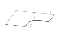
- the first step is a step of manufacturing an intermediate part with a step (see FIG. 2) in which a step shape portion 8 is provided at a position to be the flange portion 7 with respect to a flat plate (blank material) before press molding. .
- a step shape portion 8 is provided at a position to be the flange portion 7 with respect to a flat plate (blank material) before press molding.
- FIG. 2 the material portion outside the flange portion 7 is omitted.
- the material portion outside the flange portion 7 is omitted as appropriate for easy viewing.
- the third step is a step of trimming the second intermediate part and shaping the outer peripheral edge of the flange portion 7 to manufacture the stretched flange molded part. Note that the third step may be omitted and the material before molding (also referred to as a blank material) may be trimmed before the first step.
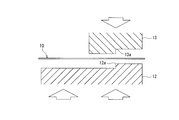
- a step forming portion including a stepped step portion is formed at a position to be a flange portion 7 of a flat plate (blank material). That is, in the first step, the step shape portion 8 is formed by sandwiching the blank material 10 between the wrinkle presser 12 and the die 13 using a mold as shown in FIG.
- a second concave outer peripheral edge portion 7a is formed on the opposing surface of the wrinkle presser 12 and the die 13 at a position opposite to the position to become the flange portion 7 along the second concave outer peripheral edge portion 7a.
- Concave and convex step portions 12a and 13a that extend so as to surround and can be engaged with each other are formed.
- the blank material 10 is sandwiched between the wrinkle presser 12 and the die 13
- the blank material is sandwiched between the concave and convex step portions 12 a, 13 a, bent in a step shape in the plate thickness direction
- a step shape portion 8 as shown in FIG. 4 is formed.
- An example of the step shape portion 8 is shown in FIG.
- the step height (height in the plate thickness direction) of the step shape portion 8 is preferably 3 mm or more and 10 mm or less.
- the formed step shape portion 8 has a ridge line 9 so as to surround the second concave outer peripheral edge portion 7a along the second concave outer peripheral edge portion 7a formed in the second step with respect to the flange portion 7 formation position. Is formed in an extended state.
- Step shape portion 8 The step shape portion 8 is formed such that the ridgeline 9 extends along the second concave outer peripheral edge portion 7a that is concave inward and so as to surround the second concave outer peripheral edge portion 7a, particularly the curved portion.
- a suitable determination method for determining the ridge line 9 of the step shape portion 8 will be described.
- the ridge line 9 that determines the step shape portion 8 of the present embodiment is composed of a first ridge line and left and right second ridge lines that are continuous with the first ridge line.
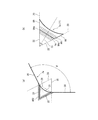
- the contour shape of the second concave outer peripheral edge portion 7a is defined by two straight portions 20 and a concave curved portion 21 connecting the two straight portions 20 as shown in FIG. To do.
- the first determination method that the angle ⁇ is 60 degrees or more and 90 degrees or less;
- the first determination method will be described with reference to FIG.
- first, of each extension line of the two straight line portions 20, each extension line part up to a position where both extension lines intersect is set as a reference line 22.
- the perpendicular perpendicular bisector formed by the two reference lines 22 is defined as a center line 23.
- the first step forming area AR1 is an area located between two orthogonal lines that are 20 mm and 50 mm from the intersection with the second concave outer peripheral edge portion 7a in the center line 23 and are orthogonal to the center line 23, respectively. (Hatched portion in FIG. 7B).
- the first ridge line 9A is determined so as to extend in the first step forming area AR1 in the direction along the second concave outer peripheral edge 7a.
- the first ridge line 9A may be a straight line or a curved line, but is preferably a line symmetrical with respect to the center line 23. In the present embodiment, the case of a straight line parallel to the orthogonal line is illustrated. Examples of the line symmetrical with respect to the center line 23 include a straight line, a partial curve of an ellipse extending to the left and right objects around the intersection with the center line 23, a parabola, and the like. However, it is preferable that there is no sharp curvature portion that becomes a corner in the middle of the first ridgeline 9A.
- the end portion 9Aa of the first ridge line 9A is an intersection with each reference line 22 or a position near the intersection.
- the left and right second ridge lines 9B extending to the outer peripheral edge of the flange are determined in succession to each end of the first ridge line 9A.
- the second ridge lines 9B are set so as to extend along the respective reference lines 22 respectively.
- the second ridgeline 9B extending along the reference line 22 is an area AR2 in two lines that are parallel to the reference line 22 and offset by 5 mm in both the left and right directions orthogonal to the reference line 22 (FIG. 7 ( It is preferable to set so as to extend in the hatched portion a).
- the connecting portion between the first ridge line 9A and the second ridge line 9B is set to be rounded and rounded.
- the step shape part 8 is formed so that the ridgeline 9 may extend so as to surround the second concave outer peripheral edge 7a along the second concave outer peripheral edge 7a.
- each vertical line 25 perpendicular to the continuous straight line portion 20 is determined from both end portions of the curved portion 21.
- each vertical line portion until the two vertical lines 25 intersect is a straight line 26 connecting both ends of the curved portion 21, and a line that is folded back to a position that becomes the flange portion 7 is a reference line 22.
- the subsequent determination method of the first ridge line 9A and the second ridge line 9B is the same as the first determination method, a description thereof will be omitted.
- the second step is a step of bending the stepped intermediate part provided with the step shape portion 8 formed in the first step into the second intermediate part.
- the vertical wall portion is obtained by relatively moving the die along the punch while sandwiching the portion to be the top plate portion 3 of the stepped intermediate part formed in the first step between the punch and the pad. 5 is drawn, and the flange portion 7 is formed to bend toward the top plate portion 3 side.
- the second process mold used in the second process will be described with reference to FIG.
- the second process mold includes a punch 30, a die 32, and a pad 31 that clamps a portion corresponding to the top plate part 3 in the stepped intermediate part.
- the plate shape in FIG. 9 represents a state in the middle of forming the vertical wall portion in the second step.
- the punch 30 has a rising portion 30A for sandwiching the top plate portion, and a flange facing surface 30a that can be opposed to at least the flange portion 7 formation position of the blank material from the lower side continuously to the lower end side of the rising portion 30A.
- the upper surface of the rising portion 30 ⁇ / b> A is a narrow pressure surface that narrows the top plate portion 3 of the molding material in cooperation with the pad 31.
- the side surface 30b of the rising portion 30A is formed with a curved surface having the same curvature as that of the first concave outer peripheral edge portion 3a, and has a shape for forming the vertical wall portion 5 in the stretch flange forming portion. That is, the height of the side surface of the rising portion 30 ⁇ / b> A is set to the same height as the vertical wall portion 5. 9 and 10 show only a part thereof.
- the pad 31 is detachably attached to the punch 30 so that a portion corresponding to the top plate portion 3 in the stepped intermediate part can be clamped in cooperation with the upper surface of the rising portion 30A of the punch 30. It has become. That is, the lower surface of the pad 31 has a shape along the first concave outer peripheral edge 3 a of the top plate 3, and at least a portion along the first concave outer peripheral edge 3 a side of the top plate 3 is punched. 30 can be sandwiched together.
- the side surface of the die 32 is a curved surface that forms the vertical wall portion 5 in cooperation with the side surface of the punch 30.
- the side surface of the die 32 is formed with an overhanging portion 32a projecting outward on the upper side surface, and the die 32 moves further downward by contacting the upper surface of the pad 31 with the overhanging portion 32a. To regulate that. And that position becomes the position of the bottom dead center.
- the height of the side surface of the die from the overhanging portion 32 a to the lower end position is set to the sum of the height of the vertical wall portion 5 and the height of the pad 31.
- a step 32b (step shape portion relief portion) is provided on the lower surface of the punch 30 facing the flange portion 7 so that the die 32 does not compress the step shape portion 8 until the die 32 moves to the bottom dead center. May be. In this case, it sets so that the protrusion part 32c below the level
- step difference 32b may not oppose the step shape part 8.
- FIG. The height difference between the flange facing surface 30a of the punch 30 and the step shape portion relief portion of the die 32 is set to be equal to or greater than the height of the step shape portion 8 formed in the stepped intermediate part.
- the step shape portion 8 is disposed in the gap formed by the die 32 and the step shape portion relief portion in the vicinity of the bottom dead center, and the step shape portion 8 is restrained and narrowed during press molding. There is nothing. As described above, the part including the step shape portion 8 is not restricted during the press molding and is freely deformed, so that stress is not concentrated on a specific part, and generation of cracks can be prevented.
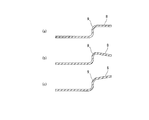
- FIG. 10 is a diagram for explaining the process until the intermediate part with the step is subjected to press molding of the intermediate part.
- 10A shows a state in which the top plate portion 3 of the molded product with a step portion is narrowed by the punch 30 and the pad 31, and
- FIG. 10B shows a state in which the die 32 is relatively press-formed at the bottom dead center. Each is shown.
- the top plate portion 3 of the intermediate part with steps is placed on the upper surface of the punch 30 and is sandwiched between the punch 30 and the pad 31.
- the pad 31 is not disposed on the entire surface corresponding to the top plate portion 3 in the stretch flange molding portion, but slightly inward from the side surface having a curvature corresponding to the first concave outer peripheral edge portion 3a of the punch 30. Place it at a shifted position.
- the die 32 is moved relative to the flange facing surface 30a along the side surface of the punch 30 up to the position shown in FIG. 10B, so that the first concave outer peripheral edge portion 3a and the first concave outer While forming the vertical wall part 5 continuing to the peripheral part 3a by drawing, the flange part 7 is shape
- the portion where the step shape portion 8 in the stepped intermediate part is formed is stretched flange forming, and tensile stress in the peripheral direction acts.
- the step shape portion 8 is formed. Since the ridge line 9 has a continuous shape, there is no crack starting point and cracks are unlikely to occur. Further, since the ridge line 9 of the step shape portion 8 is a continuous shape, a uniform tensile stress is applied without concentration of stress, so that cracks are hardly generated at this point.
- the step shape portion 8 of the present embodiment extends along the second concave outer peripheral edge portion 7a in plan view, the tensile stress acting on the step shape portion 8 can be made more uniform.
- the step shape portion 8 defined above is formed near the curved portion of the flange portion to be stretch-formed, so that the portion that becomes the second concave outer peripheral edge portion 7a is stretched and deformed in the second step. Even if it receives, distortion is easy to disperse
- the step forming portion 8 has a constant height.
- the part used as the 2nd concave outer periphery part 7a can be planarized, and a line length difference can be earned. Therefore, a strong peripheral tensile stress is unlikely to act on the second concave outer peripheral edge portion 7a.
- trimming the tensile stress acting on the portion that becomes the second concave outer peripheral edge 7a trimming along the outer shape of the product by the first step instead of the third step. Even if this occurs, the uniform stress acts on the outer end face of the step-shaped portion 8, and even if burrs or minute scratches remain on the end face, the stress concentration is reduced, The crack suppression effect can be exhibited also in terms of points.
- the part including the step shape portion 8 is not constrained by the mold, and therefore can be freely deformed (moved or escaped) three-dimensionally. Tensile stress acting in a concentrated manner can be relaxed.
- the second intermediate part is formed without cracking.
- a step shape part relief part is provided in die
- the lower surface of the die may have a shape that engages with the upper surface of the flange portion 7.
- the step shape portion 8 may be formed so as to straddle the flange portion forming position side where the step wall portion 5 becomes the vertical wall portion 5.
- a stretch flange formed part including the stretch flange formed part is manufactured by trimming a portion outside the flange part 7 of the second intermediate part.
- step shape portion 8 is formed first, even if a super high tensile material of 980 MPa class or higher is used as the base plate before press molding, cracking can be suppressed, A stretch flange molded part including a stretch flange molded part can be manufactured satisfactorily.
- a third step of trimming a portion outside the flange portion 7 is provided after the second step. If the base plate (blank material) before press molding is trimmed by punching or laser processing in advance, burrs and minute scratches remain on the material end face, and local stress is applied when deformation is applied. Concentration is likely to occur. For this reason, cracks called stretch flange cracks occur in the end face of the material during the forming process, and in the case of ultra-high tensile materials (high-strength steel sheets with a strength level of 980 MPa or higher), the cracks propagate rapidly and large cracks occur. Cheap. On the other hand, by trimming the outer portion of the flange portion 7 after the second step and shaping the outer peripheral edge of the flange portion 7, the end surface of the flange portion 7 is further stretched and the flange crack is less likely to occur.
- the ridgeline 9 of the step shape portion 8 is determined by the first determination method or the second determination method. According to this configuration, it is possible to determine an appropriate step shape portion 8 for preventing stretched flange cracking according to the degree of the second concave outer peripheral edge portion 7a.
- the second ridge line 9B extending along the reference line 22 extends in a region in two lines parallel to the target reference line 22 and offset from the reference line 22 by 5 mm in both the left and right directions. . According to this configuration, the second ridge line 9B for preventing stretch flange cracks can be determined more reliably with a predetermined degree of freedom.
- the step height of the step shape portion 8 is 3 mm or more and 10 mm or less. By defining the height of the step shape portion 8 within this range, even if an ultra-high tensile material having a strength level of 980 MPa or higher is used, it becomes possible to more reliably suppress stretch flange cracking.
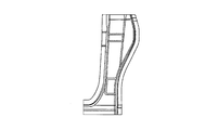
- FIG. 12 Assuming a 1180 MPa class cold-rolled steel sheet (thickness: 1.4 mm), an example of a part having an elongated flange portion 7 with an angle between straight lines forming a concave outer peripheral edge portion of 60 ° or more and 90 ° or less is shown in FIG. A-pillar forming analysis was performed. Further, a B pillar forming analysis shown in FIG. 12 was performed as an example of a part having the extending flange portion 7 in which the angle between the straight lines forming the concave outer peripheral edge portion is larger than 90 ° and not larger than 120 °.
- the processing step is a case where the step shape portion 8 is formed in the first step and the vertical wall portion 5 and the flange portion 7 are drawn in the second step as described above.
- 80 degrees was adopted as an acute angle and 110 degrees was adopted as an obtuse angle.
- the height of the vertical wall part 5 was evaluated as 40 mm.
- the first ridge line 9 ⁇ / b> A was defined as a straight line orthogonal to the center line 23.
- Example 1 the presence or absence of the step shape part 8 was evaluated in the flat part formation position.
- the flange flange 7 is stretched or cracked in the case where it has the step shape portion 8 along the second concave outer peripheral edge portion 7a at the position where the flange portion 7 is formed or not. I evaluated it.
- the determination method of the ridge line 9 of the step shape portion 8 was determined by the above-described first determination method and second determination method.
- step shape part 8 in the case of having the step shape part 8 sets the position of 30 mm from the second concave outer peripheral edge part 7a as a straight line perpendicular to the center line 23, and the step height is 8A. Standardized at 5mm.
- the second ridge line 9B was made to coincide with the reference line 22. The evaluation results are shown in Table 1.
- Example 2 As Example 2, the first ridgeline 9A position was evaluated.
- Example 2 in the case of having the step shape portion 8 for the two parts described above, is the stretch flange crack caused by the distance from the concave outer peripheral edge when setting the first ridge line 9A to the step shape portion 8? We evaluated whether or not.
- the 2nd ridgeline 9B was made to correspond with the reference line 22, and step height was unified with 5 mm. The evaluation results are shown in Table 2.
- Example 3 As Example 3, the effect of the position of the second ridgeline 9B was evaluated.
- Example 3 when the step shape portion 8 was provided for the two parts, it was evaluated whether or not the stretch flange crack was caused by the amount by which the position of the second ridge line 9B of the step was offset from the reference line 22 to the left and right. .
- the position of the first ridgeline 9A at this time was 30 mm from the second concave outer peripheral edge 7a, and the step height was unified at 5 mm.
- the evaluation results are shown in Table 3.
- the step shape portion 8 is molded to the vicinity of the vertical wall, so that sufficient shape rigidity is secured to disperse the distortion of the concave outer peripheral edge portion. It is considered that cracking occurred because it was not possible.
- Example 4 As Example 4, the step height of the step shape was evaluated. In Example 4, when the step part 8 was provided for the two parts, it was evaluated whether stretch flange cracking would occur depending on the height of the step part 8. The second ridge line 9B of the step was made to coincide with the reference line 22, and the position of the first ridge line 9A was unified at 30 mm from the end face of the blank curved portion. The evaluation results are shown in Table 4.
Landscapes
- Engineering & Computer Science (AREA)
- Mechanical Engineering (AREA)
- Shaping Metal By Deep-Drawing, Or The Like (AREA)
- Blow-Moulding Or Thermoforming Of Plastics Or The Like (AREA)
- Moulds For Moulding Plastics Or The Like (AREA)
- Shaping Of Tube Ends By Bending Or Straightening (AREA)
- Casting Or Compression Moulding Of Plastics Or The Like (AREA)
Abstract
Description
そのような伸びフランジ成形部品としては、例えば自動車の車体骨格部品として用いられるプレス成形部品であって、平面視でL字形状部又はT字形状部を有する部品が例示できる。本発明は、特に980MPa以上の超ハイテン材を素材としてプレス成形で製造する場合に好適な技術である。
絞り成形は、通常、パンチ、ダイ、およびシワ押さえ(ブランクホルダー)からなる金型を用いて行われ、金属板の周囲をダイとブランクホルダーで押さえた状態で、パンチとダイの間の距離を近づけて金属板に絞り加工を施す方法である。また、曲げ成形は、通常、パンチ、パッドおよびダイからなる金型を用いて行われ、金属板をパンチとパッドで挟んだ状態で、ダイを相対移動させることによって曲げ加工を施す方法である。
前記のプレス成形によって特に割れが発生しやすい部位は、湾曲部の伸びフランジ成形部である。この部位では、材料端面が周縁方向に伸ばされながら材料が流入する変形状態となる。
そして、この特許文献1には、L字形状部のL字下側部に対応する部位が縦壁部に向けて引き込まれるため、フランジ部において過度な引張りが発生するのが軽減され、割れの発生を防止できると記載されている(特許文献1の段落番号0009を参照)。
本発明は、かかる課題に着目してなされたものであり、伸びフランジ成形を伴って製造される伸びフランジ成形部品を、伸びフランジ割れを抑制して製造できる伸びフランジ成形部品の製造方法を目的としている。
前記天板部の凹状外周縁部を第1凹状外周縁部と定義し、前記フランジ部の凹状外周縁部を第2凹状外周縁部と定義した場合、
前記フランジ部となる位置に第2凹状外周縁部を囲むように稜線が延び且つ板厚方向に屈曲したステップ形状部を形成した後前記縦壁部を形成し、
前記第2凹状外周縁部の輪郭形状を、2本の直線部と、その2本の直線部間を繋ぐ凹状の曲線部で規定したときに、前記2本の直線部の各延長線で形成される前記第2凹状外周縁部側の交角が60度以上90度以下であり、
前記2本の直線部の各延長線のうち、両延長線が交差する位置までの各延長線部分をそれぞれ基準線とし、
前記2本の基準線で形成される角の垂線2等分線を中央線とし、
前記中央線における前記第2凹状外周縁部との交点からの距離が20mm及び50mmでそれぞれ当該中央線に直交する2本の直交線の間に位置する領域を第1ステップ形成領域とし、
前記ステップ形状部の稜線は、前記第1ステップ形成領域AR1内を前記第2凹状外周縁部に沿った方向に延びる第1の稜線と、その第1の稜線の端部にそれぞれ連続して前記各基準線に沿って延びる左右の第2の稜線とから構成されることを特徴とする伸びフランジ成形部品の製造方法である。
前記天板部の凹状外周縁部を第1凹状外周縁部と定義し、前記フランジ部の凹状外周縁部を第2凹状外周縁部と定義した場合、
前記フランジ部となる位置に第2凹状外周縁部を囲むように稜線が延び且つ板厚方向に屈曲したステップ形状部を形成し、
前記第2凹状外周縁部の輪郭形状を、2本の直線部と、その2本の直線部間を繋ぐ凹状の曲線部で規定したときに、前記2本の直線部の各延長線で形成される前記第2凹状外周縁部側の交角が90度以上120度以下であり、
前記曲線部の両端部からそれぞれ連続する前記直線部に垂直な各垂直線のうち、当該2つの垂直線が交差するまでの各垂直線部分を、前記曲線部の両端部を結んだ線で、フランジ部となる位置に折り返した線をそれぞれ基準線とし、
前記2本の基準線で形成される角の垂線2等分線を中央線とし、
前記中央線における前記第2凹状外周縁部との交点からの距離が20mm及び50mmでそれぞれ当該中央線に直交する2本の直交線の間に位置する領域を第1ステップ形成領域AR1とし、
前記ステップ形状部の稜線は、前記第1ステップ形成領域内を前記第2凹状外周縁部に沿った方向に延びる第1の稜線と、その第1の稜線の端部にそれぞれ連続して前記各基準線に沿って延びる左右の第2の稜線とから構成されることを特徴とする伸びフランジ成形部品の製造方法である。
以上のことから、本発明によれば、仮に強度レベル980MPa級以上の超ハイテン材から伸びフランジ成形を伴って伸びフランジ成形部品を製造する場合であっても、伸びフランジ割れを抑制して製造することが可能となる。
本実施形態では、980MPa級以上の超ハイテン材をプレス成形前の素板(ブランク材)として用いて、伸びフランジ成形部となる部位を有する伸びフランジ成形部品を製造する場合を例に挙げて説明する。本発明の製造方法は、強度が980MPa以下の金属板からなる素材であっても適用可能である。
また、以下においては、伸びフランジ成形部品における伸びフランジ成形部となる部位を含む部分に着目して説明するものとし、各図においては当該部分のみを図示しており、当該部分を「伸びフランジ成形部1」という。なお、金型においても当該部位を成形する部位のみを図示している。他の部位も同時に成形しても良いことは勿論である。
本実施形態の製造方法で製造される伸びフランジ成形部1は、図1に示すように、外周縁の一部が内方に凹むように湾曲した凹状外周縁部3aを有する天板部3と、天板部3における凹状外周縁部3aに沿って成形された縦壁部5と、縦壁部5に連続して前記天板部3側に屈曲し且つ外周縁の一部が内方に凹むように湾曲した凹状外周縁部7aを有するフランジ部7を有しており、フランジ部7がプレス成形の際に伸びフランジ成形となる部位である。
第1工程では、プレス成形前の平板状の素板(ブランク材)に対し、フランジ部7となる位置にステップ形状部8を付与したステップ付き中間部品(図2参照)を製造する工程である。図2では、フランジ部7より外方の素材部分を省略している。他の図においても、見やすくするために適宜、フランジ部7より外方の素材部分を省略している。
第3工程では、第2の中間部品をトリミングして、フランジ部7の外周縁を整形して、前記の伸びフランジ成形部品を製造する工程である。
なお、第3工程を省略して、第1工程の前に、成形前の素材(ブランク材とも呼ぶ)をトリミングするようにしても良い。
[第1工程]
第1工程は、図2に示すように、平板状の素板(ブランク材)のフランジ部7となる位置にステップ状の段部からなるステップ形成部を形成する。
即ち、第1工程は、図3に示すような金型を使用して、ブランク材10を、シワ押え12とダイ13で挟持してステップ形状部8を形成する。
この形成されたステップ形状部8は、フランジ部7形成位置に対し、第2工程で形成される第2凹状外周縁部7aに沿って該第2凹状外周縁部7aを囲むように、稜線9が延びた状態に形成される。
ステップ形状部8は、内側に凹の第2凹状外周縁部7aに沿って且つ該第2凹状外周縁部7a、特に湾曲部を囲むように稜線9が延びるように形成されている。
このステップ形状部8の稜線9の決定方法の好適な決定方法の一例について、次に説明する。
本実施形態では、まず第2凹状外周縁部7aの輪郭形状を、図6に示すように、2本の直線部20と、その2本の直線部20間を繋ぐ凹状の曲線部21で規定する。
そして、前記2本の直線部20の各延長線で形成される前記凹状外周縁部側の交角の角度θに応じて、該角度θが60度以上90度以下の第1の決定方法と、角度θが90度以上120度以下の第2の決定方法の2つに分ける。交角の角度θが90度の場合は第1の決定方法でも、第2の決定方法でも構わない。
第1の決定方法を図7を参照して説明する。
第1の決定方法では、まず、前記2本の直線部20の各延長線のうち、両延長線が交差する位置までの各延長線部分をそれぞれ基準線22とする。
続けて、2本の基準線22で形成される角の垂線2等分線を中央線23とする。
更に、中央線23における第2凹状外周縁部7aとの交点からの距離が20mm及び50mmでそれぞれ当該中央線23に直交する2本の直交線の間に位置する領域を第1ステップ形成領域AR1(図7(b)のハッチング部分)とする。
次に、その第1の稜線9Aの各端部に連続して、フランジ外周縁部まで延びる左右の第2の稜線9Bを決定する。第2の稜線9Bは、それぞれ各基準線22に沿って延びるように設定する。
基準線22に沿って延びる第2の稜線9Bは、基準となる基準線22と平行で且つ該基準線22と直交する左右両方向にそれぞれ5mmオフセットした2本の線内の領域AR2(図7(a)のハッチング部分)内を延びるように設定することが好ましい。
このようにすることで、ステップ形状部8は、第2凹状外周縁部7aに沿って該第2凹状外周縁部7aを囲むように稜線9が延びるように形成される。
第2の決定方法を図8を参照して説明する。
曲線部21の両端部から、それぞれ連続する前記直線部20に垂直な各垂直線25を決定する。
次に、その2つの垂直線25が交差するまでの各垂直線部分を、前記曲線部21の両端部を結んだ直線26で、フランジ部7となる位置に折り返した線をそれぞれ基準線22とする。
以降の第1の稜線9A及び第2の稜線9Bの決定方法は、前記の第1の決定方法と同じであるため、省略する。
第2工程は、第1工程で成形したステップ形状部8を付与したステップ付き中間部品を、第2の中間部品に曲げ成形する工程である。
この第2工程では、第1工程で形成したステップ付き中間部品の天板部3となる部分を、パンチとパッドで挟んだ状態で、ダイをパンチに沿って相対移動させることで、縦壁部5を絞り成形すると共に、フランジ部7を天板部3側に屈曲するように成形する。
第2工程で用いる第2工程用金型について、図9を参照して説明する。
第2工程用金型は、図9に示すように、パンチ30と、ダイ32と、ステップ付き中間部品における天板部3に相当する部位を挟圧するパッド31とを有している。図9の板形状は、第2工程で縦壁部の成形途中の状態を表している。
パンチ30は、天板部挟圧用の立上り部30Aと、その立上り部30Aの下端側に連続してブランク材の少なくともフランジ部7形成位置に下側から対向可能なフランジ対向面30aを有する。
立上り部30Aの上面は、パッド31と協働して被成形材の天板部3を狭圧する狭圧面になっている。
また、立上り部30Aの側面30bは、第1凹状外周縁部3aと同じ曲率の湾曲面が形成されており、伸びフランジ成形部における縦壁部5を成形する形状になっている。即ち、立上り部30Aの側面の高さは、縦壁部5と同じ高さに設定されている。
なお、図9及び図10においては、その一部のみを図示している。
パッド31は、パンチ30に対して離接可能に設けられており、ステップ付き中間部品における天板部3に相当する部位を、パンチ30の立上り部30A上面と協働して挟圧できるようになっている。即ち、パッド31は、下面が天板部3の第1凹状外周縁部3aに沿った形状を有して、天板部3における少なくとも第1凹状外周縁部3a側に沿った部分を、パンチ30と一緒に挟み込み可能となっている。
ダイ32の側面は、パンチ30の側面と協働して縦壁部5を成形する湾曲面になっている。そのダイ32の側面は、その上部側面には外方に張り出した張出部32aが形成され、その張出部32aがパッド31の上面に当接することで、それ以上ダイ32が下方に移動することを規制する。そして、その位置が下死点の位置となる。また、その張出部32aから下端位置までのダイ側面の高さは、縦壁部5の高さとパッド31の高さとの和に設定されている。
パンチ30のフランジ対向面30aとダイ32のステップ形状部逃がし部との高低差は、ステップ付き中間部品に形成したステップ形状部8の高さと等しいか該高さよりも大きくなるように設定する。
以上のように構成された第2工程用金型を用いた第2工程について、第2工程用金型の動作と共に、図10に基づいて説明する。
図10は、ステップ付き中間部品が中間部品プレス成形されるまでを説明する図である。図10(a)は、パンチ30とパッド31でステップ部付き成形品の天板部3を狭圧した状態を、図10(b)はダイ32を相対的にプレス成形下死点の状態をそれぞれ示している。
この状態で、図10(b)の位置まで、ダイ32をパンチ30の側面に沿って、フランジ対向面30aに向けて相対移動させることで、第1凹状外周縁部3a及びその第1凹状外周縁部3aに連続する縦壁部5を絞り成形で形成すると共に、フランジ部7を成形する。
また、第1工程において、前記で規定したステップ形状部8を伸び成形されるフランジ部の湾曲部近傍に成形することで、第2凹状外周縁部7aとなる部分が第2工程時に伸びフランジ変形を受けた場合でも、ステップ形状部8の形状剛性によりひずみが分散し易く、第2凹状外周縁部7aとなる部分にひずみが集中することを防ぐことができる。
このように、第2凹状外周縁部7aとなる部分に作用する引張応力を均一化することで、仮に、第3工程の代わりに、第1工程までに製品の外形形状に沿ってトリミングを実施したとしても、ステップ形状部8の外側の端面に対しても均一化された応力が作用することになり、端面にバリや微小なキズなどが残留していても応力集中が緩和して、この点においても割れ抑制効果を奏することができる。
以上のようにして、割れが発生することなく第2の中間部品が成形される。
ここで、前記説明では、ダイ下面にステップ形状部逃がし部を設ける場合を例示しているが。ダイ下面を、フランジ部7の上面に係合する形状としておいても勿論構わない。
また前記ステップ形状部8が縦壁部5となる位置のフランジ部形成位置側にも跨るように形成されていても良い。
第3工程では、第2の中間部品のフランジ部7の外側の部位をトリミングして伸びフランジ成形部を含む伸びフランジ成形部品を製造する。
(1)ブランク材を、第2凹状外周縁部7aに沿って前記フランジ部7となる位置に第2凹状外周縁部7aを囲むように稜線9が延び且つ板厚方向に屈曲したステップ形状部8を形成した後、第1凹状外周縁部3aに沿って縦壁部5を絞り成形する。
この構成によれば、仮に強度レベル980MPa級以上の超ハイテン材を使用したとしても、伸びフランジ割れが発生しやすい第2凹状外周縁部7aを囲むようにステップ形状部8を予め設けておくことで、曲げ成形の際における伸びフランジ割れを抑制出来る。
以上のことから、本実施形態によれば、仮に強度レベル980MPa級以上の超ハイテン材から伸びフランジ成形を伴って伸びフランジ成形部品を製造する場合であっても、伸びフランジ割れを抑制して製造することが可能となる。
予め、プレス成形前の素板(ブランク材)に対し、打ち抜き加工やレーザー加工でトリミングすると、材料端面にはバリや微小なキズなどが残留しており、変形を加えたときに局所的な応力集中が発生しやすい状態になっている。そのため、材料端面には成形途中で伸びフランジ割れと称する亀裂が発生し、超ハイテン材(強度レベルが980MPa級以上の高強度鋼板)の場合、その亀裂が急速に伝播して大きな割れが発生しやすい。
これに対し、第2工程後にフランジ部7の外側部位をトリミングして、フランジ部7の外周縁を整形することで、更にフランジ部7の端面に伸びフランジ割れが生じ難くなる。
この構成によれば、第2凹状外周縁部7aの程度に応じて、伸びフランジ割れ防止のための適切なステップ形状部8を決定することが可能となる。
この構成によれば、伸びフランジ割れ防止のための第2の稜線9Bを、所定の自由度を持ってより確実決定可能となる。
この範囲にステップ形状部8の高さを規定することで、仮に強度レベル980MPa級以上の超ハイテン材を使用したとしても、伸びフランジ割れをより確実に抑えることが可能となる。
また、凹状外周縁部を形成する直線間の角度が90°より大きく120°以下の伸びフランジ部7を有する部品の例として図12に示すBピラーの成形解析を実施した。
ここでは、鋭角として80度を採用し、鈍角として110度を採用した。
また、縦壁部5の高さを40mmとして評価を行った。
また第1の稜線9Aは中央線23に直交する直線で定義した。
前記の解析は汎用動的陽解法ソフトウェアLS-DYNAを使用し、成形解析後、伸びフランジ部7に10%以上の板厚減少率が確認された場合に割れが発生したものとして、成形性の評価を行った。
そして実施例1として、フラット部形成位置にステップ形状部8の有無の評価を行った。
実施例1では、前記の2部品を対象に、フランジ部7形成位置に第2凹状外周縁部7aに沿ったステップ形状部8を有する場合と、有さない場合とにおいて伸びフランジ割れが生じるかどうかを評価した。
ステップ形状部8の稜線9の決定方法は、上述の第1の決定方法及び第2の決定方法で決定した。
評価結果を表1に示す。

すなわち、ステップ形状部8を有さない場合では、第2工程の成形によって割れ危険部にひずみが集中することで伸びフランジ割れしてしまうのに対して、ステップ形状部8を有する場合では凹状外周縁部に加わるひずみが分散することにより伸びフランジ割れを抑制することができたと考えられる。
実施例2として、第1の稜線9A位置について評価を行った。
実施例2では、前記2部品を対象に、ステップ形状部8を有する場合において、ステップ形状部8に第1の稜線9Aを設定する際の凹状外周縁部からの距離によって伸びフランジ割れが生じるかどうかについて評価を行った。
このとき、第2の稜線9Bは基準線22と一致させ、ステップ高さは5mmで統一した。
評価結果を表2に示す。
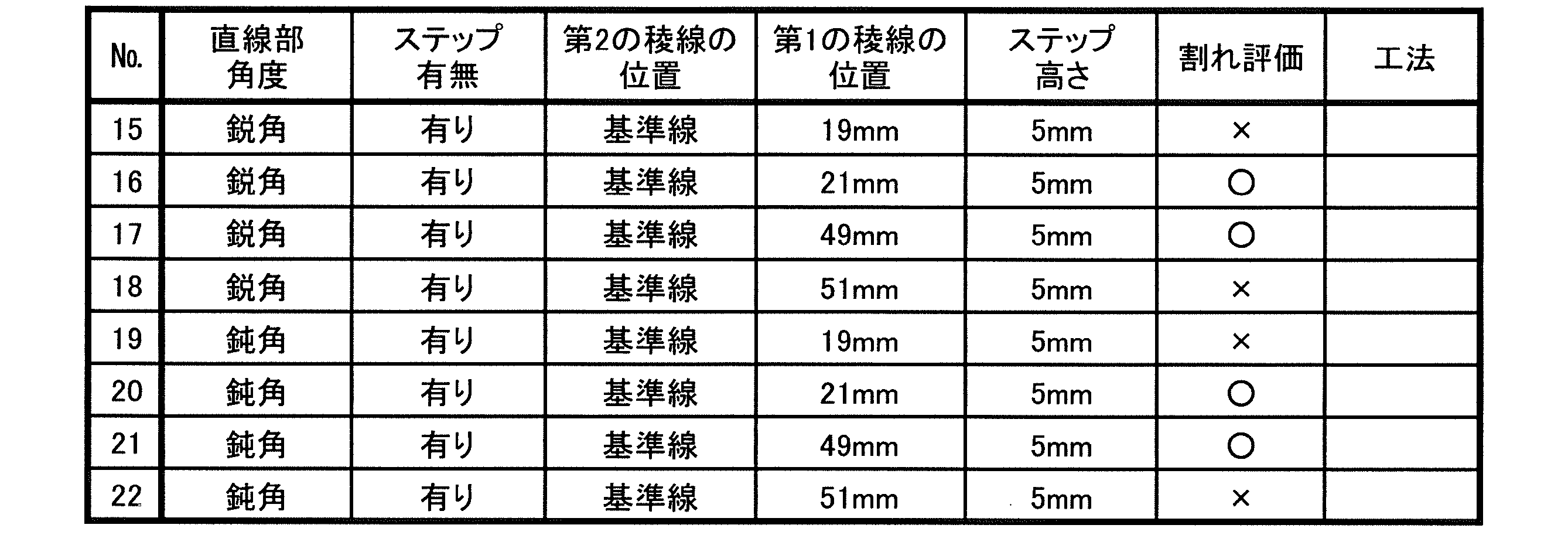
これは、第1の稜線9Aを20mm以下に設定すると、第2凹状外周縁部7a近傍でステップ形状部8が成形されるため、ステップ形状部8の成形時に発生するひずみが第2凹状外周縁部7aに伝播してしまうため、割れが発生し易くなると考えられる。また、第1の稜線9Aが50mm以上に設定されると、第2工程の成形中にステップが平坦化する効果が小さくなり、線長差が小さくなってしまうため割れが発生されたものと考えられる。
実施例3として第2の稜線9Bの位置による効果について評価した。
実施例3では、前記2部品を対象に、ステップ形状部8を有する場合において、ステップの第2の稜線9B位置を基準線22から左右にオフセットする量によって伸びフランジ割れが生じるかどうかを評価した。
このときの第1の稜線9Aの位置は第2凹状外周縁部7aから30mmとし、ステップ高さは5mmで統一した。
評価結果を表3に示す。
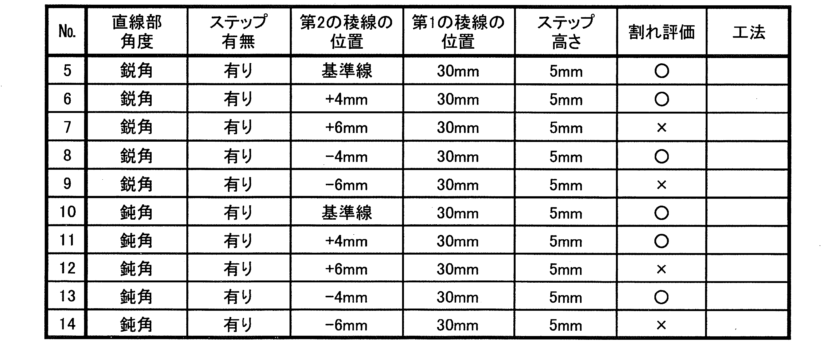
これは、基準線22から内側へのオフセット量が5mmより大きくなると、第2凹状外周縁部7aに成形されるステップの領域が狭くなり、ひずみを分散できる範囲が狭くなってしまう他、第2凹状外周縁部7a上にステップの段差が成形されてしまうため、縁部での割れを誘発する恐れがあるからと推定される。また、基準線22から外側へのオフセット量が5mmを越えると、ステップ形状部8が縦壁付近にまで成形されてしまうため、凹状外周縁部のひずみを分散させるために十分な形状剛性を確保できないため、割れが発生したものと考えられる。
実施例4として、ステップ形状のステップ高さを評価した。
実施例4では、前記2部品を対象に、ステップ形状部8を有する場合において、ステップ形状部8の高さによって伸びフランジ割れが生じるかどうかについて評価した。
ステップの第2の稜線9Bは基準線22と一致させ、第1の稜線9Aの位置はブランク湾曲部の端面から30mmで統一した。
評価結果を表4に示す。
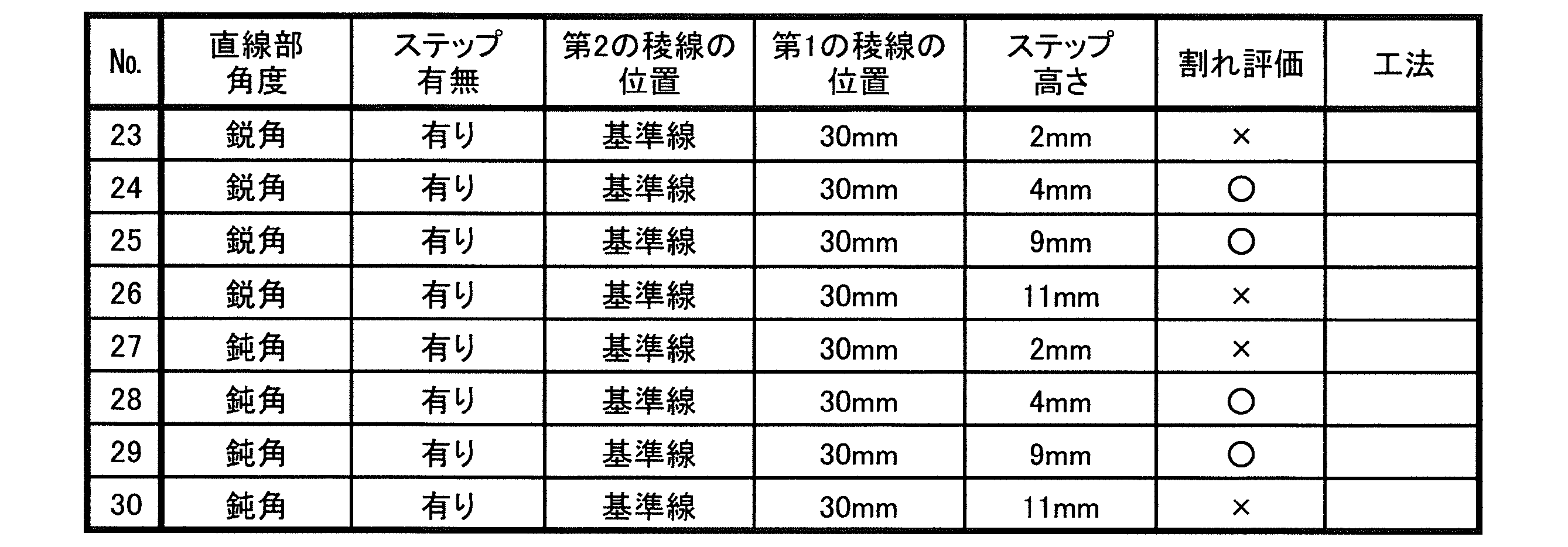
これはステップの高さが3mm未満の場合では、伸びフランジ割れを抑制する要因の一つである線長差の増加が見込めないため、割れが生じ易く、ステップ高さが10mmを越えると、第1工程においてステップ形状部8を成形する段階で割れが発生してしまうと推定される。
ここでは、限られた数の実施形態を参照しながら説明したが、権利範囲はそれらに限定されるものではなく、上記の開示に基づく各実施形態の改変は当業者にとって自明なことである。
3 天板部
3a 第1凹状外周縁部
5 縦壁部
7 フランジ部
7a 第2凹状外周縁部
8 ステップ形状部
9 稜線
9A 第1の稜線
9B 第2の稜線
10 ブランク材
12a 段部
13 ダイ
20 直線部
21 曲線部
22 基準線
23 中央線
25 垂直線
30 パンチ
30a フランジ対向面
31 パッド
32 ダイ
32a 張出部
32b 段差
32c 突出部分
AR1 第1ステップ形成領域
AR2 領域
θ 角度
Claims (4)
- 外周縁の一部が内方に凹むように湾曲した凹状外周縁部を有する天板部と、その天板部の前記凹状外周縁部に連続する縦壁部と、その縦壁部に連続して前記天板部側に屈曲し且つ外周縁の一部が内方に凹むように湾曲した凹状外周縁部を有するフランジ部を備える伸びフランジ成形部品を製造する製造方法であって、
前記天板部の凹状外周縁部を第1凹状外周縁部と定義し、前記フランジ部の凹状外周縁部を第2凹状外周縁部と定義した場合、
前記フランジ部となる位置に第2凹状外周縁部を囲むように稜線が延び且つ板厚方向に屈曲したステップ形状部を形成した後前記縦壁部を形成し、
前記第2凹状外周縁部の輪郭形状を、2本の直線部と、その2本の直線部間を繋ぐ凹状の曲線部で規定したときに、前記2本の直線部の各延長線で形成される前記第2凹状外周縁部側の交角が60度以上90度以下であり、
前記2本の直線部の各延長線のうち、両延長線が交差する位置までの各延長線部分をそれぞれ基準線とし、
前記2本の基準線で形成される角の垂線2等分線を中央線とし、
前記中央線における前記第2凹状外周縁部との交点からの距離が20mm及び50mmでそれぞれ当該中央線に直交する2本の直交線の間に位置する領域を第1ステップ形成領域とし、
前記ステップ形状部の稜線は、前記第1ステップ形成領域AR1内を前記第2凹状外周縁部に沿った方向に延びる第1の稜線と、その第1の稜線の端部にそれぞれ連続して前記各基準線に沿って延びる左右の第2の稜線とから構成されることを特徴とする伸びフランジ成形部品の製造方法。 - 外周縁の一部が内方に凹むように湾曲した凹状外周縁部を有する天板部と、その天板部の前記凹状外周縁部に連続する縦壁部と、その縦壁部に連続して前記天板部側に屈曲し且つ外周縁の一部が内方に凹むように湾曲した凹状外周縁部を有するフランジ部を備える伸びフランジ成形部品を製造する製造方法であって、
前記天板部の凹状外周縁部を第1凹状外周縁部と定義し、前記フランジ部の凹状外周縁部を第2凹状外周縁部と定義した場合、
前記フランジ部となる位置に第2凹状外周縁部を囲むように稜線が延び且つ板厚方向に屈曲したステップ形状部を形成した後前記縦壁部を形成し、
前記第2凹状外周縁部の輪郭形状を、2本の直線部と、その2本の直線部間を繋ぐ凹状の曲線部で規定したときに、前記2本の直線部の各延長線で形成される前記第2凹状外周縁部側の交角が90度以上120度以下であり、
前記曲線部の両端部からそれぞれ連続する前記直線部に垂直な各垂直線のうち、当該2つの垂直線が交差するまでの各垂直線部分を、前記曲線部の両端部を結んだ線で、フランジ部となる位置に折り返した線をそれぞれ基準線とし、
前記2本の基準線で形成される角の垂線2等分線を中央線とし、
前記中央線における前記第2凹状外周縁部との交点からの距離が20mm及び50mmでそれぞれ当該中央線に直交する2本の直交線の間に位置する領域を第1ステップ形成領域AR1とし、
前記ステップ形状部の稜線は、前記第1ステップ形成領域内を前記第2凹状外周縁部に沿った方向に延びる第1の稜線と、その第1の稜線の端部にそれぞれ連続して前記各基準線に沿って延びる左右の第2の稜線とから構成されることを特徴とする伸びフランジ成形部品の製造方法。 - 前記基準線に沿って延びる第2の稜線は、対象とする前記基準線と平行で且つ該基準線から左右両方向にそれぞれ5mmオフセットした2本の線内の領域内を延びることを特徴とする請求項1又は請求項2に記載した伸びフランジ成形部品の製造方法。
- 前記ステップ形状部のステップの高さは3mm以上10mm以下とすることを特徴とする請求項1~請求項3のいずれか1項に記載した伸びフランジ成形部品の製造方法。
Priority Applications (4)
| Application Number | Priority Date | Filing Date | Title |
|---|---|---|---|
| MX2017016135A MX377748B (es) | 2015-06-16 | 2016-05-23 | Metodo para fabricar un componente con reborde concavo |
| JP2016555802A JP6052478B1 (ja) | 2015-06-16 | 2016-05-23 | 伸びフランジ成形部品の製造方法 |
| KR1020177035156A KR101947943B1 (ko) | 2015-06-16 | 2016-05-23 | 신장 플랜지 성형 부품의 제조 방법 |
| CN201680034914.7A CN107708884B (zh) | 2015-06-16 | 2016-05-23 | 拉伸凸缘成型部件的制造方法 |
Applications Claiming Priority (2)
| Application Number | Priority Date | Filing Date | Title |
|---|---|---|---|
| JP2015121390 | 2015-06-16 | ||
| JP2015-121390 | 2015-06-16 |
Publications (1)
| Publication Number | Publication Date |
|---|---|
| WO2016203904A1 true WO2016203904A1 (ja) | 2016-12-22 |
Family
ID=57545253
Family Applications (1)
| Application Number | Title | Priority Date | Filing Date |
|---|---|---|---|
| PCT/JP2016/065154 Ceased WO2016203904A1 (ja) | 2015-06-16 | 2016-05-23 | 伸びフランジ成形部品の製造方法 |
Country Status (5)
| Country | Link |
|---|---|
| JP (1) | JP6052478B1 (ja) |
| KR (1) | KR101947943B1 (ja) |
| CN (1) | CN107708884B (ja) |
| MX (1) | MX377748B (ja) |
| WO (1) | WO2016203904A1 (ja) |
Cited By (3)
| Publication number | Priority date | Publication date | Assignee | Title |
|---|---|---|---|---|
| CN113231511A (zh) * | 2021-06-03 | 2021-08-10 | 四川航天长征装备制造有限公司 | 一种盒型钣金件四角手工外拔缘快速成形方法 |
| CN113286672A (zh) * | 2019-01-11 | 2021-08-20 | 杰富意钢铁株式会社 | 冲压成形方法、板状材料的落料、中间成形品、冲压成形品的制造方法和冲压成形品 |
| CN113458275A (zh) * | 2021-07-08 | 2021-10-01 | 安徽江淮汽车集团股份有限公司 | 一种车体外覆盖件翻边展开工艺 |
Families Citing this family (6)
| Publication number | Priority date | Publication date | Assignee | Title |
|---|---|---|---|---|
| KR102023541B1 (ko) * | 2015-08-28 | 2019-09-20 | 제이에프이 스틸 가부시키가이샤 | 신장 플랜지 성형 부품의 제조 방법 |
| DE112018007878T5 (de) * | 2018-07-31 | 2021-04-22 | Nippon Steel Corporation | Streckbördelwerkzeug, Streckbördelverfahren unter Verwendung desselben und Bauteil mit Streckflansch |
| KR102482506B1 (ko) * | 2019-02-26 | 2022-12-28 | 제이에프이 스틸 가부시키가이샤 | 굽힘 균열 평가 방법, 굽힘 균열 평가 시스템, 및 프레스 성형 부품의 제조 방법 |
| CA3135330C (en) * | 2019-03-28 | 2023-06-27 | Honda Motor Co., Ltd. | Press forming method |
| EP4592001A4 (en) | 2022-09-21 | 2025-11-19 | Nippon Steel Corp | METHOD FOR MANUFACTURING PRESS-MOLDED ARTICLES AND PRESS-MOLDED DEVICE |
| CN116020941A (zh) * | 2022-11-21 | 2023-04-28 | 柳州宝钢汽车零部件有限公司 | 一种b柱下段软区回弹控制方法 |
Citations (3)
| Publication number | Priority date | Publication date | Assignee | Title |
|---|---|---|---|---|
| JPH0576951A (ja) * | 1991-09-18 | 1993-03-30 | Toyota Motor Corp | プレス成形方法 |
| JPH08103828A (ja) * | 1994-10-04 | 1996-04-23 | Nissan Motor Co Ltd | 低温絞り成形方法及び絞り成形用金型装置及びプレス機械 |
| JP2015178133A (ja) * | 2014-02-25 | 2015-10-08 | Jfeスチール株式会社 | 伸びフランジ成形部品の製造方法 |
Family Cites Families (5)
| Publication number | Priority date | Publication date | Assignee | Title |
|---|---|---|---|---|
| JP4815997B2 (ja) | 2005-10-26 | 2011-11-16 | 日産自動車株式会社 | プレス成形方法およびプレス成形装置 |
| JP4879812B2 (ja) | 2007-04-24 | 2012-02-22 | 新日本製鐵株式会社 | 形状凍結性に優れたプレス成形方法 |
| JP5211799B2 (ja) | 2008-03-27 | 2013-06-12 | マツダ株式会社 | プレス成形方法及びプレス成形金型装置 |
| KR101472645B1 (ko) * | 2010-05-19 | 2014-12-15 | 신닛테츠스미킨 카부시키카이샤 | L자 형상을 갖는 부품의 프레스 성형 방법 |
| RU2636426C2 (ru) * | 2013-01-07 | 2017-11-23 | Ниппон Стил Энд Сумитомо Метал Корпорейшн | Прессованный компонент и способ и устройство для его изготовления |
-
2016
- 2016-05-23 KR KR1020177035156A patent/KR101947943B1/ko not_active Expired - Fee Related
- 2016-05-23 CN CN201680034914.7A patent/CN107708884B/zh not_active Expired - Fee Related
- 2016-05-23 WO PCT/JP2016/065154 patent/WO2016203904A1/ja not_active Ceased
- 2016-05-23 MX MX2017016135A patent/MX377748B/es active IP Right Grant
- 2016-05-23 JP JP2016555802A patent/JP6052478B1/ja not_active Expired - Fee Related
Patent Citations (3)
| Publication number | Priority date | Publication date | Assignee | Title |
|---|---|---|---|---|
| JPH0576951A (ja) * | 1991-09-18 | 1993-03-30 | Toyota Motor Corp | プレス成形方法 |
| JPH08103828A (ja) * | 1994-10-04 | 1996-04-23 | Nissan Motor Co Ltd | 低温絞り成形方法及び絞り成形用金型装置及びプレス機械 |
| JP2015178133A (ja) * | 2014-02-25 | 2015-10-08 | Jfeスチール株式会社 | 伸びフランジ成形部品の製造方法 |
Cited By (6)
| Publication number | Priority date | Publication date | Assignee | Title |
|---|---|---|---|---|
| CN113286672A (zh) * | 2019-01-11 | 2021-08-20 | 杰富意钢铁株式会社 | 冲压成形方法、板状材料的落料、中间成形品、冲压成形品的制造方法和冲压成形品 |
| EP3909697A4 (en) * | 2019-01-11 | 2022-03-02 | JFE Steel Corporation | PRESSING PROCESS, BLANK OF SHEET MATERIAL, INTERMEDIATE, METHOD OF MAKING A PRESSING AND PRESSING |
| US12115571B2 (en) | 2019-01-11 | 2024-10-15 | Jfe Steel Corporation | Press-forming method, blank member for sheet-shaped material, intermediate formed product, method for manufacturing press-formed product, and press-formed product |
| CN113231511A (zh) * | 2021-06-03 | 2021-08-10 | 四川航天长征装备制造有限公司 | 一种盒型钣金件四角手工外拔缘快速成形方法 |
| CN113231511B (zh) * | 2021-06-03 | 2023-03-28 | 四川航天长征装备制造有限公司 | 一种盒型钣金件四角手工外拔缘快速成形方法 |
| CN113458275A (zh) * | 2021-07-08 | 2021-10-01 | 安徽江淮汽车集团股份有限公司 | 一种车体外覆盖件翻边展开工艺 |
Also Published As
| Publication number | Publication date |
|---|---|
| CN107708884B (zh) | 2019-06-25 |
| KR101947943B1 (ko) | 2019-02-13 |
| JPWO2016203904A1 (ja) | 2017-06-29 |
| KR20180004771A (ko) | 2018-01-12 |
| MX377748B (es) | 2025-03-11 |
| MX2017016135A (es) | 2018-04-18 |
| JP6052478B1 (ja) | 2016-12-27 |
| CN107708884A (zh) | 2018-02-16 |
Similar Documents
| Publication | Publication Date | Title |
|---|---|---|
| JP6052478B1 (ja) | 伸びフランジ成形部品の製造方法 | |
| CN111727089B (zh) | 冲压部件的制造方法、冲压成型装置和冲压成型用的金属板 | |
| KR101614755B1 (ko) | 프레스 성형 방법 | |
| CN111836689A (zh) | 冲压部件的制造方法、冲压成型装置以及冲压成型用的金属板 | |
| JP6156608B1 (ja) | 伸びフランジ成形部品の製造方法 | |
| KR20220134017A (ko) | 프레스 부품의 제조 방법, 프레스 성형용의 금속판, 및 고장력 강판 | |
| KR102450454B1 (ko) | 프레스 성형 방법 | |
| JP2009202189A (ja) | 部材長手方向の平面内に屈曲部を有する金属製断面ハット型形状部材およびそのプレス成形方法 | |
| JP6015784B2 (ja) | 伸びフランジ成形部品の製造方法 | |
| JPWO2015092963A1 (ja) | プレス成形方法、及びプレス成形部品の製造方法 | |
| JP6319382B2 (ja) | 伸びフランジ成形部品の製造方法 | |
| JP4907590B2 (ja) | 部材長手方向の平面外で屈曲部を有する金属製断面ハット型形状部材およびそのプレス成形方法 | |
| JP6907911B2 (ja) | プレス成形品の製造方法 | |
| JP6319383B2 (ja) | 伸びフランジ成形部品の製造方法 | |
| JP6330766B2 (ja) | プレス成形方法 | |
| JP2021159951A (ja) | 板金成形品の製造方法、板金成形品の製造装置、及びフランジアップ工具 | |
| JP6358208B2 (ja) | プレス成形用金型 | |
| JP2020049494A (ja) | プレス成形部品の製造方法、及びプレス成形部品 | |
| WO2015079791A1 (ja) | プレス成形方法 | |
| JP6119716B2 (ja) | プレス成形方法及びプレス成形用金型 | |
| CN118715070A (zh) | 冲压成型方法以及冲压成型品的制造方法 | |
| JP2021169119A (ja) | プレス部品の製造方法、プレス成形用の金属板、及び高張力鋼板 | |
| JP2017202523A (ja) | 伸びフランジを有する成形体及びその製造方法 |
Legal Events
| Date | Code | Title | Description |
|---|---|---|---|
| ENP | Entry into the national phase |
Ref document number: 2016555802 Country of ref document: JP Kind code of ref document: A |
|
| 121 | Ep: the epo has been informed by wipo that ep was designated in this application |
Ref document number: 16811379 Country of ref document: EP Kind code of ref document: A1 |
|
| ENP | Entry into the national phase |
Ref document number: 20177035156 Country of ref document: KR Kind code of ref document: A |
|
| WWE | Wipo information: entry into national phase |
Ref document number: MX/A/2017/016135 Country of ref document: MX |
|
| NENP | Non-entry into the national phase |
Ref country code: DE |
|
| 122 | Ep: pct application non-entry in european phase |
Ref document number: 16811379 Country of ref document: EP Kind code of ref document: A1 |