WO2016203767A1 - 膨張タービン装置 - Google Patents
膨張タービン装置 Download PDFInfo
- Publication number
- WO2016203767A1 WO2016203767A1 PCT/JP2016/002899 JP2016002899W WO2016203767A1 WO 2016203767 A1 WO2016203767 A1 WO 2016203767A1 JP 2016002899 W JP2016002899 W JP 2016002899W WO 2016203767 A1 WO2016203767 A1 WO 2016203767A1
- Authority
- WO
- WIPO (PCT)
- Prior art keywords
- bearing
- gas
- chamber
- hydrostatic bearing
- radial
- Prior art date
- Legal status (The legal status is an assumption and is not a legal conclusion. Google has not performed a legal analysis and makes no representation as to the accuracy of the status listed.)
- Ceased
Links
Images




Classifications
-
- F—MECHANICAL ENGINEERING; LIGHTING; HEATING; WEAPONS; BLASTING
- F16—ENGINEERING ELEMENTS AND UNITS; GENERAL MEASURES FOR PRODUCING AND MAINTAINING EFFECTIVE FUNCTIONING OF MACHINES OR INSTALLATIONS; THERMAL INSULATION IN GENERAL
- F16C—SHAFTS; FLEXIBLE SHAFTS; ELEMENTS OR CRANKSHAFT MECHANISMS; ROTARY BODIES OTHER THAN GEARING ELEMENTS; BEARINGS
- F16C32/00—Bearings not otherwise provided for
- F16C32/06—Bearings not otherwise provided for with moving member supported by a fluid cushion formed, at least to a large extent, otherwise than by movement of the shaft, e.g. hydrostatic air-cushion bearings
- F16C32/0603—Bearings not otherwise provided for with moving member supported by a fluid cushion formed, at least to a large extent, otherwise than by movement of the shaft, e.g. hydrostatic air-cushion bearings supported by a gas cushion, e.g. an air cushion
- F16C32/0614—Bearings not otherwise provided for with moving member supported by a fluid cushion formed, at least to a large extent, otherwise than by movement of the shaft, e.g. hydrostatic air-cushion bearings supported by a gas cushion, e.g. an air cushion the gas being supplied under pressure, e.g. aerostatic bearings
-
- F—MECHANICAL ENGINEERING; LIGHTING; HEATING; WEAPONS; BLASTING
- F25—REFRIGERATION OR COOLING; COMBINED HEATING AND REFRIGERATION SYSTEMS; HEAT PUMP SYSTEMS; MANUFACTURE OR STORAGE OF ICE; LIQUEFACTION SOLIDIFICATION OF GASES
- F25J—LIQUEFACTION, SOLIDIFICATION OR SEPARATION OF GASES OR GASEOUS OR LIQUEFIED GASEOUS MIXTURES BY PRESSURE AND COLD TREATMENT OR BY BRINGING THEM INTO THE SUPERCRITICAL STATE
- F25J1/00—Processes or apparatus for liquefying or solidifying gases or gaseous mixtures
- F25J1/0002—Processes or apparatus for liquefying or solidifying gases or gaseous mixtures characterised by the fluid to be liquefied
- F25J1/0005—Light or noble gases
- F25J1/001—Hydrogen
-
- F—MECHANICAL ENGINEERING; LIGHTING; HEATING; WEAPONS; BLASTING
- F25—REFRIGERATION OR COOLING; COMBINED HEATING AND REFRIGERATION SYSTEMS; HEAT PUMP SYSTEMS; MANUFACTURE OR STORAGE OF ICE; LIQUEFACTION SOLIDIFICATION OF GASES
- F25J—LIQUEFACTION, SOLIDIFICATION OR SEPARATION OF GASES OR GASEOUS OR LIQUEFIED GASEOUS MIXTURES BY PRESSURE AND COLD TREATMENT OR BY BRINGING THEM INTO THE SUPERCRITICAL STATE
- F25J1/00—Processes or apparatus for liquefying or solidifying gases or gaseous mixtures
- F25J1/02—Processes or apparatus for liquefying or solidifying gases or gaseous mixtures requiring the use of refrigeration, e.g. of helium or hydrogen ; Details and kind of the refrigeration system used; Integration with other units or processes; Controlling aspects of the process
- F25J1/0243—Start-up or control of the process; Details of the apparatus used; Details of the refrigerant compression system used
- F25J1/0257—Construction and layout of liquefaction equipments, e.g. valves, machines
-
- F—MECHANICAL ENGINEERING; LIGHTING; HEATING; WEAPONS; BLASTING
- F16—ENGINEERING ELEMENTS AND UNITS; GENERAL MEASURES FOR PRODUCING AND MAINTAINING EFFECTIVE FUNCTIONING OF MACHINES OR INSTALLATIONS; THERMAL INSULATION IN GENERAL
- F16C—SHAFTS; FLEXIBLE SHAFTS; ELEMENTS OR CRANKSHAFT MECHANISMS; ROTARY BODIES OTHER THAN GEARING ELEMENTS; BEARINGS
- F16C33/00—Parts of bearings; Special methods for making bearings or parts thereof
- F16C33/72—Sealings
- F16C33/76—Sealings of ball or roller bearings
- F16C33/80—Labyrinth sealings
-
- F—MECHANICAL ENGINEERING; LIGHTING; HEATING; WEAPONS; BLASTING
- F25—REFRIGERATION OR COOLING; COMBINED HEATING AND REFRIGERATION SYSTEMS; HEAT PUMP SYSTEMS; MANUFACTURE OR STORAGE OF ICE; LIQUEFACTION SOLIDIFICATION OF GASES
- F25J—LIQUEFACTION, SOLIDIFICATION OR SEPARATION OF GASES OR GASEOUS OR LIQUEFIED GASEOUS MIXTURES BY PRESSURE AND COLD TREATMENT OR BY BRINGING THEM INTO THE SUPERCRITICAL STATE
- F25J2240/00—Processes or apparatus involving steps for expanding of process streams
- F25J2240/02—Expansion of a process fluid in a work-extracting turbine (i.e. isentropic expansion), e.g. of the feed stream
Definitions
- the present invention relates to an expansion turbine device, and more particularly to a leakage prevention technique for an expansion turbine device including a static pressure gas bearing.
- a liquefaction system for liquefying a source gas such as hydrogen gas or helium gas
- a source gas such as hydrogen gas or helium gas
- a refrigerant circulation line for circulating the refrigerant gas
- a heat exchanger for cooling the source gas with the refrigerant.
- the refrigerant gas circulating in the refrigerant circulation line is compressed by the compressor, then adiabatically expanded by the expansion turbine, and the temperature is lowered.
- the raw material gas is cooled by exchanging heat with the cooled refrigerant gas in the heat exchanger.
- the expansion turbine needs a bearing to support the rotating shaft. If a liquid bearing using lubricating oil is applied as the bearing, the lubricating oil may be mixed into the refrigerant gas passing through the expansion turbine. Therefore, it is preferable to apply a gas bearing using the same type of gas as the refrigerant gas to the bearing.
- gas bearings static pressure gas bearings can suppress friction between the bearing surface and the rotating shaft at the time of starting and stopping the liquefaction system, and are suitable for ultra-high speed rotation. For this reason, static pressure gas bearings are used as bearings for expansion turbines (see, for example, Patent Document 1).
- An expansion turbine using a static pressure gas bearing includes a bearing supply line for supplying a bearing gas of the same type as the refrigerant gas to the static pressure gas bearing, and a bearing exhaust line for exhausting the bearing gas that has passed through the static pressure gas bearing. .
- a rotation shaft is inserted into a bearing chamber inside the expansion turbine, and a bearing supply line and a bearing exhaust line are communicated with each other.
- a turbine impeller provided at one end of the rotating shaft is accommodated in the expansion chamber.
- an expansion chamber inlet into which refrigerant gas flows is formed on the outer peripheral side of the turbine impeller, and an expansion chamber outlet from which refrigerant gas flows out is formed in the central axis direction.
- the brake impeller provided at the other end of the rotating shaft is accommodated in the braking gas chamber.
- a communication path that connects the outlet and the inlet of the braking gas chamber is formed, and a closed circuit including a brake impeller is formed.
- a labyrinth seal is provided on the back surface of the turbine impeller of the expansion turbine in order to prevent low-temperature refrigerant gas from leaking from the expansion chamber to the bearing chamber (see, for example, Patent Document 2).
- the labyrinth seal has a certain gap with the rotating shaft, leakage cannot be completely prevented as long as there is a differential pressure of the seal.
- the leakage of low-temperature gas from the expansion chamber to the bearing chamber increases, the efficiency of the expansion turbine decreases, and the bearing chamber is cooled, so that the clearance between the rotating shaft and the radial hydrostatic bearing changes, and in some cases it rotates. Contact between the shaft and the radial hydrostatic bearing occurs.
- an object of the present invention is to suppress low-temperature gas seal leakage in an expansion turbine having a static pressure gas bearing.
- An expansion turbine apparatus has an expansion chamber, a braking gas chamber, and a shaft insertion hole formed therein, and the shaft insertion hole communicates the expansion chamber and the braking gas chamber and has a rotating shaft. Is inserted into the main body, the turbine impeller accommodated in the expansion chamber and expands the refrigerant gas, and the brake accommodated in the braking gas chamber and braked by the same type of braking gas as the refrigerant gas.
- An impeller, the shaft insertion hole with a gap between them, the turbine impeller provided at one end, the rotation shaft provided with the brake impeller at the other end, and the shaft insertion hole A static pressure gas bearing that is provided at the inlet and is rotatably supported by the static pressure of a bearing gas of the same type as the refrigerant gas that is supplied from the outlet and discharged from the outlet; and on the expansion chamber side of the bearing chamber A first labyrinth seal provided in a portion between the first gas and the hydrostatic gas bearing, and a refrigerant gas leaking from the expansion chamber to the bearing chamber through the bearing gas and the first labyrinth seal.
- a mixed gas discharge path for discharging a mixed gas for discharging a mixed gas; a first back pressure adjusting valve provided in the mixed gas discharge path for adjusting a back pressure of the static pressure gas bearing; and provided in the mixed gas discharge path; A temperature sensor for measuring the temperature of the gas, and a control for controlling the first back pressure regulating valve so as to increase the back pressure of the static pressure gas bearing when the temperature of the mixed gas flowing through the mixed gas discharge path decreases.
- the static pressure gas bearing includes first and second radial hydrostatic bearings that support the rotary shaft so as to be rotatable in the radial direction, and a thrust static bearing that supports the rotary shaft so as to be rotatable in the axial direction.
- the first radial hydrostatic bearing, the thrust hydrostatic bearing, and the second radial hydrostatic bearing are sequentially located in the bearing chamber from the expansion chamber toward the braking gas chamber.
- the first labyrinth seal is provided at a portion between the end of the bearing chamber on the expansion chamber side and the portion where the first radial hydrostatic bearing is provided, and the first radial static seal is provided.
- the upstream end of the mixed gas discharge path may be connected to the outlet of the pressure bearing, and the upstream end of the dedicated bearing gas discharge path may be connected to the outlet of the thrust hydrostatic bearing and the outlet of the second radial hydrostatic bearing.
- back pressure control independent of other bearings is performed only on the first radial hydrostatic bearing located on the expansion chamber side.
- Back pressure control may have the adverse effect of reducing bearing performance if the back pressure is increased too much.
- only the first radial hydrostatic bearing on the expansion chamber side adjacent to the first labyrinth seal is controlled. Therefore, the purpose can be achieved, and the degree of freedom in setting the back pressure of other bearings is increased, so that suitable control can be realized.
- the static pressure gas bearing includes first and second radial hydrostatic bearings that rotatably support the rotary shaft in the radial direction, and a thrust static shaft that rotatably supports the rotary shaft in the axial direction.
- the first radial hydrostatic bearing, the thrust hydrostatic bearing, and the second radial hydrostatic bearing are sequentially located in the bearing chamber from the expansion chamber toward the braking gas chamber.
- a second labyrinth seal provided in a portion of the bearing chamber between the first radial hydrostatic bearing and the thrust hydrostatic bearing, an outlet of the thrust hydrostatic bearing, and the second
- a bearing gas dedicated discharge path whose upstream end is connected to an outlet of the radial hydrostatic bearing, and a bearing gas dedicated discharge path are provided in the exhaust path dedicated to the bearing gas, and the back pressure of the thrust hydrostatic bearing and the second radial hydrostatic bearing is reduced.
- a second back pressure regulating valve that regulates, one end connected to the outlet of the braking gas chamber, and one end connected to the inlet of the braking gas chamber, and one end connected to the braking line; And a ventilation path having the other end connected to the bearing gas dedicated discharge path.
- the pressure of the braking line and the back pressure of the thrust hydrostatic bearing and the second radial hydrostatic bearing are made uniform through the ventilation path, independent of the bearing back pressure of the first radial hydrostatic bearing.
- Pressure control can be performed.
- the distance between a 2nd radial hydrostatic bearing and an expansion chamber can be shortened by moving a 2nd labyrinth seal between a 1st radial hydrostatic bearing and a thrust hydrostatic bearing. It is possible to reduce the axial length of the rotary shaft from the second radial hydrostatic bearing to the expansion chamber side, thereby reducing the mass of the rotating body and improving the vibration stability.
- the static pressure gas bearing includes first and second radial hydrostatic bearings that rotatably support the rotating shaft in a radial direction, and a thrust static bearing that rotatably supports the rotating shaft in an axial direction.
- the first radial hydrostatic bearing, the thrust hydrostatic bearing, and the second radial hydrostatic bearing are sequentially located in the bearing chamber from the expansion chamber toward the braking gas chamber.
- the first labyrinth seal is provided at a portion between the end of the bearing chamber on the expansion chamber side and the portion where the first radial hydrostatic bearing is provided, and the first radial static seal is provided.
- An upstream end of the mixed gas discharge path is connected to an outlet on the expansion chamber side of the pressure bearing, an outlet on the braking gas chamber side of the first radial hydrostatic bearing, an outlet of the thrust hydrostatic bearing, and the second radial Stillness
- the upstream end of the bearing gas only discharge path to the outlet of the bearing may be connected.
- seal leakage of low temperature gas can be suppressed in an expansion turbine apparatus including a static pressure gas bearing. Thereby, the efficiency fall of a turbine and the cooling of a bearing chamber can be suppressed.
- FIG. 1 is a partial cross-sectional view showing the structure of the expansion turbine apparatus according to the first embodiment.
- the expansion turbine device 1 has an expansion chamber 21, a braking gas chamber 20, and a shaft insertion hole 22 formed in the main body 10.
- the main body 10 is formed in a casing shape, for example.
- the shaft insertion hole 22 is formed so that the expansion chamber 21 and the braking gas chamber 20 communicate with each other and the rotation shaft 13 can be inserted.
- the rotary shaft 13 is inserted into the shaft insertion hole 22 with a gap, the turbine impeller 11 is provided at one end, and the brake impeller 12 is provided at the other end.
- the rotary shaft 13 extends in the vertical direction within the main body 10 and is supported so as to be rotatable about the vertical axis.
- the turbine impeller 11 is accommodated in the expansion chamber 21 and configured to expand the refrigerant gas.
- the turbine impeller 11 is formed at the lower end of the rotating shaft 13.
- An expansion chamber inlet 24 and an expansion chamber outlet 26 are formed in the lower part of the main body 10, and thereby the expansion chamber 21 that houses the turbine impeller 11 communicates with the turbine line 16 (see FIG. 5) outside the main body 10.
- the refrigerant that has flowed into the expansion chamber inlet 24 from the turbine line 16 is injected toward the turbine impeller 11.
- the refrigerant gas expands and cools down as the turbine impeller 11 rotates, and then flows out of the main body 10 from the expansion chamber outlet 26.
- the brake impeller 12 is housed in the braking gas chamber 20 and is braked by the same type of braking gas as the refrigerant gas.
- the brake impeller 12 is formed at the upper end of the rotating shaft 13.
- a brake gas chamber inlet 27 and a brake gas chamber outlet 29 are formed in the upper part of the main body 10, whereby the brake gas chamber 20 accommodating the brake impeller 12 communicates with a brake line 15 (see FIG. 5) outside the main body 10. To do.
- the normal-temperature braking gas that has flowed into the braking gas chamber inlet 27 from the braking line 15 flows directly toward the brake impeller 12.
- the braking gas is compressed along with the rotation of the brake impeller 12 to increase in pressure and temperature, and then returns from the braking gas chamber outlet 29 to the braking gas chamber inlet 27 through the braking line 15.
- the static pressure gas bearing 14 is provided in a bearing chamber 23 formed in the shaft insertion hole 22, and is generated by the static pressure of the same type of bearing gas as the refrigerant gas supplied from the expansion chamber inlet 24 and discharged from the expansion chamber outlet 26.
- the rotating shaft 13 is rotatably supported.
- the static pressure gas bearing 14 includes radial static pressure bearings 14a and 14d that support the rotary shaft 13 rotatably in the radial direction, and thrust static pressure bearings 14b and 14c that support the rotary shaft 13 rotatably in the axial direction. .
- These static pressure gas bearings 14 a to 14 d are formed in a substantially cylindrical shape and are provided so as to surround the outer peripheral side of the rotating shaft 13.
- the first radial hydrostatic bearing 14d, the first thrust hydrostatic bearing 14c, the second thrust hydrostatic bearing 14b, and the radial hydrostatic bearing 14a are sequentially located in the bearing chamber 23 from the expansion chamber 21 toward the braking gas chamber 20. It is provided as follows.
- the second thrust hydrostatic bearing 14b and the first thrust hydrostatic bearing 14c are arranged so as to sandwich the thrust collar 34 protruding in the radial direction from the upper and lower central portion of the rotating shaft 13 in the vertical direction.
- a first common air supply passage 35a, a second common air supply passage 35b, and a common exhaust passage 36 are formed.
- the first common supply passage 35a, the second common supply passage 35b, and the common exhaust passage 36 are formed at different positions in the circumferential direction.
- the first common air supply passage 35a communicates with the bearing gas inlet 49, and is a passage through which the bearing gas supplied to the gap between the second radial hydrostatic bearing 14a and the first radial hydrostatic bearing 14d flows.
- the two common air supply passages 35b communicate with the bearing gas inlet 49 and are passages through which the bearing gas supplied to the gap between the second thrust hydrostatic bearing 14b and the first thrust hydrostatic bearing 14c flows.
- first common supply passage 35a and the second common supply passage 35b are configured independently, but may be configured in common.
- the common exhaust passage 36 communicates with the bearing gas outlet 50 and is a passage through which the bearing gas discharged from the gaps between the static pressure gas bearings 14a to 14d flows.
- the first common supply passage 35a is branched into a first supply passage 37 and a second supply passage 38.
- the second common supply passage 35 b is branched into a third supply passage 43 and a fourth supply passage 44.
- the first air supply passage 37 is a passage through which the bearing gas supplied to the gap of the second radial hydrostatic bearing 14a flows.
- the second air supply passage 38 is a passage through which the bearing gas supplied to the gap of the first radial hydrostatic bearing 14d flows.
- the third air supply passage 43 is a passage through which the bearing gas supplied to the gap of the second thrust hydrostatic bearing 14b flows.
- the fourth air supply passage 44 is a passage through which the bearing gas supplied to the gap of the first thrust hydrostatic bearing 14c flows.
- the common exhaust passage 36 communicates with the first exhaust passage 39, the second exhaust passage 40, the third exhaust passage 41, and the fourth exhaust passage 42.
- the first exhaust passage 39 is a passage through which the bearing gas discharged upward from the clearance of the second radial hydrostatic bearing 14a flows.
- the second exhaust passage 40 is a passage through which the bearing gas discharged downward from the gap of the second radial hydrostatic bearing 14a and the bearing gas discharged upward from the gap of the second thrust hydrostatic bearing 14b flow.
- the third exhaust passage 41 is a passage through which the bearing gas discharged downward from the clearance of the first thrust hydrostatic bearing 14c and the bearing gas discharged upward from the clearance of the first radial hydrostatic bearing 14d flow.
- the fourth exhaust passage 42 is a passage through which the bearing gas discharged downward from the clearance of the first radial hydrostatic bearing 14d flows, and the fourth exhaust passage 42 passes from the expansion chamber 21 through the first labyrinth seal 30. The refrigerant gas leaking into the bearing chamber 23 of the first radial hydrostatic bearing 14d flows.
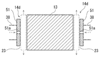
- FIG. 2 schematically shows a cross-sectional view of the first radial hydrostatic bearing 14d.
- a bearing member 51 is formed in a substantially cylindrical shape so as to surround the outer peripheral side of the rotating shaft 13.
- the bearing member 51 has a gap with the rotary shaft 13.
- a plurality of nozzle holes (bearing inlets) 51 a are formed in the bearing member 51 in the circumferential direction.
- the bearing gas flowing through the second air supply passage 38 branched from the first common air supply passage 35a in FIG. 1 is injected to the rotary shaft 13 from the nozzle hole 51a.
- a bearing film (dotted line) of the first radial hydrostatic bearing 14 d is formed between the inner peripheral surface of the bearing member 51 and the outer peripheral surface of the rotary shaft 13.
- the bearing gas (dotted arrow) discharged upward from one end (bearing outlet) of the gap of the first radial hydrostatic bearing 14d is discharged from the third exhaust passage 41 of FIG.
- the bearing gas (dotted arrow) discharged downward from the other end (bearing outlet) of the clearance of the first radial hydrostatic bearing 14d is discharged from the fourth exhaust passage 42 of FIG. 1 through the common exhaust passage 36.
- the second radial hydrostatic bearing 14a in FIG. 1 also has the same configuration as the first radial hydrostatic bearing 14d, a bearing film is formed by bearing gas, and both ends of the gap (bearing outlet) of the second radial hydrostatic bearing 14a are formed.
- the bearing gas discharged from the upper and lower sides is guided to the common exhaust passage 36 through the first exhaust passage 39 and the second exhaust passage 40.
- FIG. 3 schematically shows a cross-sectional view of the thrust hydrostatic bearings 14b and 14c.
- the rotating shaft 13 and the thrust collar 34 are arranged with a gap inside the main body 10.
- the third air supply passage 43 is a passage branched from the second common air supply passage 35b of FIG. 1 and through which the bearing gas supplied to the gap of the second thrust hydrostatic bearing 14b flows.
- the fourth air supply passage 44 is a passage that branches from the second common air supply passage 35b and through which the bearing gas supplied to the gap of the first thrust hydrostatic bearing 14c flows.
- the bearing gas flowing through the third air supply passage 43 is injected from the nozzle hole (bearing inlet) 43a, and the bearing film (dotted line) of the second thrust hydrostatic bearing 14b is connected to the lower end surface of the inner wall 22a of the shaft insertion hole 22 and the thrust collar. 34 is formed between the upper end surface of 34.
- the bearing gas flowing through the fourth air supply passage 44 is injected from the nozzle hole 44 a, and the bearing film (dotted line) of the first thrust hydrostatic bearing 14 c is connected to the upper end surface of the inner wall 22 a of the shaft insertion hole 22 and the lower end surface of the thrust collar 34. Formed between.
- the bearing gas (dotted arrow) discharged upward from one end (bearing outlet) of the gap of the second thrust hydrostatic bearing 14b is discharged from the second exhaust passage 40 of FIG.
- the bearing gas (dotted arrow) discharged downward from the other end (bearing outlet) of the clearance of the first thrust hydrostatic bearing 14c is discharged from the third exhaust passage 41 of FIG. 1 through the common exhaust passage 36.
- the bearing gas that has flowed out (dotted line arrow) is also discharged through the common exhaust passage 36.
- the bearing gas inlet 49 communicates with the first common supply passage 35a and the second common supply passage 35b.
- the bearing gas outlet 50 communicates with the common exhaust passage 36.
- the bearing gas is supplied from the bearing gas inlet 49 to the static pressure gas bearings 14a to 14d in the main body 10 of the expansion turbine apparatus 1.
- the same type of gas as the refrigerant gas is used for the bearing gas.
- FIG. 4 is a schematic diagram showing the configuration of the first labyrinth seal 30.
- the first labyrinth seal 30 has an inner peripheral surface that surrounds the outer peripheral side of the rotary shaft 13 with a certain distance from the rotary shaft 13.
- a plurality of concave and convex gaps are provided on the inner peripheral surface. Each time the refrigerant enters the gap, the leakage pressure gradually decreases.
- a second labyrinth seal 31 having a similar structure is also provided at a portion between the end on the braking gas chamber 20 side and the portion where the second radial hydrostatic bearing 14a is provided (see FIG. 1). The leakage of the refrigerant between the braking gas and the bearing gas in the braking gas chamber 20 is suppressed.
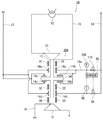
- FIG. 5 is a schematic diagram showing the overall configuration of the expansion turbine device 1 of FIG. In the following, description of the already described configuration is omitted.
- the expansion turbine apparatus 1 includes a main body 10, a braking line 15, a turbine line 16, a bearing supply line 17, an exhaust line 18, a temperature sensor 60, and a first back pressure adjustment valve 80. And a control device 90.
- the braking line 15 is a pipe for circulating the braking gas and supplying the braking gas to the brake impeller 12.
- One end of the brake line 15 is connected to the brake gas chamber inlet 27 of the brake gas chamber 20 of FIG. 1, and the other end of the brake line 15 is connected to the brake gas chamber outlet 29 of the brake gas chamber 20.
- a heat exchanger 53 is provided in the middle of the braking line 15.
- the heat exchanger 53 lowers and lowers the pressure of the braking gas circulating in the braking line 15.
- the braking gas circulating in the braking line 15 is compressed and raised in temperature and raised in the process of passing through the brake impeller 12, but lowered and lowered in pressure as it passes through the heat exchanger 53.
- the turbine line 16 is a pipe for supplying refrigerant gas to the turbine impeller 11.
- One end of the turbine line 16 is connected to the expansion chamber inlet 24 of the expansion chamber 21 in FIG. 1, and the other end of the turbine line 16 is connected to the expansion chamber outlet 26 of the expansion chamber 21.
- the low-temperature and high-pressure refrigerant compressed by a compressor (not shown) is introduced to the turbine impeller 11 upstream of the expansion chamber inlet 24 of the expansion chamber 21.
- the turbine impeller 11 lowers the temperature and pressure of the low-temperature and high-pressure refrigerant by adiabatic expansion.
- the bearing supply line 17 is configured to supply bearing gas to the static pressure gas bearings 14a to 14d.
- One end of the bearing supply line 17 is connected to, for example, a feed line that feeds the raw material gas of the liquefaction system, and the other end of the bearing supply line 17 is connected to a bearing gas inlet 49 of the main body 10 (see FIG. 1).
- the bearing supply line 17 supplies bearing gas to each of the second radial hydrostatic bearing 14a, the second thrust hydrostatic bearing 14b, the first thrust hydrostatic bearing 14c, and the first radial hydrostatic bearing 14d. It is configured.
- the bearing supply line 17 communicates with the first common air supply passage 35a and the second common air supply passage 25b in FIG.
- Bearing gas is supplied to the second radial hydrostatic bearing 14a and the first radial hydrostatic bearing 14d through the first air supply passage 37 and the second air supply passage 38 branched from the first common air supply passage 35a.
- the bearing gas is supplied to the first thrust hydrostatic bearing 14c and the second thrust hydrostatic bearing 14b through the third supply passage 43 and the fourth supply passage 44 branched from the supply passage 35b (see FIG. 1). .
- the exhaust line 18 has an upstream end connected to the outlet of the bearing chamber 23 of the static pressure gas bearings 14a to 14d, and discharges the bearing gas that has passed through the static pressure gas bearings 14a to 14d.
- the upstream end of the exhaust line 18 is connected to the bearing gas outlet 50 of FIG.
- the exhaust line 18 includes a first exhaust passage 39, a second exhaust passage 40, a third exhaust passage 41, a fourth exhaust passage 42, and a common exhaust passage 36 in FIG. 1 (see FIG. 1).
- the exhaust line 18 connects the bearing gas that has passed through the static pressure gas bearings 14a to 14d and the refrigerant gas that leaks from the turbine line 16 (expansion chamber) to the bearing chamber 23 of the first radial static pressure bearing 14d through the first labyrinth seal 30.
- a mixed gas discharge path configured to discharge the mixed gas.
- the temperature sensor 60 is provided in the exhaust line 18 and is configured to measure a bearing exhaust temperature T 1 of the exhaust line 18.
- the temperature sensor 60 is configured to output the measured temperature information to the control device 90.
- the first back pressure adjusting valve 80 is provided in the exhaust line 18 and is configured to adjust the back pressure of the exhaust line 18 based on a command from the control device 90.
- the control device 90 is provided in the exhaust line 18 and controls the opening and closing of the first back pressure regulating valve 80 based on the bearing exhaust temperature T 1 measured by the temperature sensor 60.
- the control device 90 has a function of controlling not only the expansion turbine device 1 but also other devices such as a compressor.
- the control device 90 is, for example, a microcomputer mainly composed of a CPU, a ROM, and an input / output interface. Process data such as measured values of the pressure and temperature of the exhaust line 18, turbine rotational speed, and the like are input to the input side of the control device 90.
- a first back pressure adjusting valve 80, a supply valve, a discharge valve, and the like are connected to the output side of the control device 90.
- the CPU executes a control program stored in the ROM.
- the CPU controls the first back pressure regulating valve 80 so as to obtain the bearing back pressure as set while monitoring the temperature measurement value of the process data.
- the control device 90 when the bearing exhaust temperatures T 1 is lower than the reference value T S, is controlled so as to increase the bearing back pressure P 1.
- reference temperature T S is the value of a predetermined value or a predetermined range in a normal.
- the expansion turbine device 1 rotates at an ultra high speed by a low-temperature and high-pressure refrigerant supplied through the turbine line 16.
- bearing gas is supplied from the bearing supply line 17 to the gaps between the static pressure gas bearings 14 a to 14 d of the turbine body 10.
- the rotating shaft 13 is rotatably supported in the main body 10, and the radial load and the thrust load of the rotating shaft 13 are supported.
- the bearing gas of the static pressure gas bearings 14a to 14d is discharged.
- a first labyrinth seal 30 is provided at a portion between an end of the bearing chamber 23 in which the turbine impeller 11 is accommodated on the expansion chamber 21 side and a portion where the first radial hydrostatic bearing 14d is provided.
- the exhaust line 18 contains a mixed gas of the bearing gas and the leaked refrigerant gas.
- the temperature of the exhaust line 18 measured by the temperature sensor 60 decreases.
- the control device 90 when the bearing exhaust temperature T 1 of the exhaust line 18 is lower than the reference value T S, is controlled so as to increase the bearing back pressure P 1. Thereby, since the differential pressure
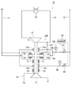
- FIG. 6 is a schematic diagram showing a configuration of an expansion turbine apparatus 1A according to the second embodiment.
- the upstream end of the exhaust line (mixed gas discharge path) 18 is connected to the outlet of the first radial hydrostatic bearing 14d as compared with the first embodiment (FIG. 5).
- the upstream end of the bearing exhaust line (bearing gas exclusive discharge path) 18a is connected to the outlet of the first thrust hydrostatic bearing 14c and the second thrust hydrostatic bearing 14b and the outlet of the second radial hydrostatic bearing 14a. Is different.
- the exhaust line 18 is configured to discharge the bearing gas that has passed through the first radial hydrostatic bearing 14d.
- the bearing exhaust line 18a is configured to discharge the bearing gas that has passed through the thrust hydrostatic bearings 14b and 14c and the second radial hydrostatic bearing 14a.
- the downstream end of the bearing exhaust line 18 a is configured to merge in the middle of the exhaust line 18.
- a third labyrinth seal 32 is provided in a portion between the first radial hydrostatic bearing 14d and the first thrust hydrostatic bearing 14c.
- a temperature sensor 60 and a first back pressure adjusting valve 80 are provided in the exhaust line 18.
- a pressure sensor 100 and a second back pressure regulating valve 110 are provided in the bearing exhaust line 18a.
- Pressure control of the static pressure gas bearings 14a, 14b, and 14c is performed by the pressure sensor 100 and the second back pressure regulating valve 110.
- back pressure control independent of the other static pressure gas bearings 14a, 14b, and 14c is performed only on the first radial static pressure bearing 14d located on the expansion chamber 21 side.
- the back pressure control may have a harmful effect that the bearing performance deteriorates if the back pressure is increased too much.
- the first radial hydrostatic bearing 14d on the expansion chamber 21 side adjacent to the first labyrinth seal 30 is used.
- the purpose can be achieved by controlling only the pressure, and the degree of freedom in setting the back pressure of the other static pressure gas bearings 14a, 14b, 14c is increased, and suitable control can be realized.
- FIG. 7 is a schematic diagram showing a configuration of an expansion turbine apparatus 1B according to the third embodiment.
- the expansion turbine apparatus 1B has a second labyrinth seal 31 between the first radial hydrostatic bearing 14d and the first thrust hydrostatic bearing 14c, as compared with the first embodiment (FIG. 5). It is provided in the part.
- the upstream end of the exhaust line (mixed gas discharge path) 18 is connected to the outlet of the first radial hydrostatic bearing 14d, the outlets of the first thrust hydrostatic bearing 14c and the second thrust hydrostatic bearing 14b, and the second radial hydrostatic bearing.
- the upstream end of a bearing exhaust line (bearing gas exclusive discharge path) 18a is connected to the outlet 14a.
- a pressure sensor 100 and a second back pressure adjusting valve 110 are provided in the bearing exhaust line 18a.
- the present embodiment is different in that it further includes a ventilation path 15b having one end connected to the brake line 15 and the other end connected to the bearing exhaust line 18a.
- the pressure of the braking line 15 and the back pressure of the thrust hydrostatic bearings 14b and 14c and the second radial hydrostatic bearing 14a are made uniform via the ventilation path 15b.
- the pressure can be controlled by the pressure sensor 100 and the second back pressure regulating valve 110.
- the second labyrinth seal 31 is moved between the first radial hydrostatic bearing 14d and the thrust hydrostatic bearing 14c, so that the distance between the second radial hydrostatic bearing 14a and the expansion chamber 21 is increased.
- the axial length of the rotary shaft 13 from the second radial hydrostatic bearing 14a to the expansion chamber 21 side can be shortened, and the mass of the rotary body can be reduced and the vibration stability can be improved. .
- FIG. 8 is a block diagram showing a configuration of an expansion turbine apparatus 1C according to the fourth embodiment.
- the upstream end of the exhaust line 18 is connected only to the outlet on the expansion chamber side of the first radial hydrostatic bearing 14d, as compared with the first embodiment (FIG. 5).
- the upstream end of the bearing exhaust line 18a are connected to the outlet on the braking gas chamber side of the first radial hydrostatic bearing 14d, the outlets of the thrust hydrostatic bearings 14b and 14c, and the outlet of the second radial hydrostatic bearing 14a. Is different.
- the exhaust line 18 discharges the mixed gas of the bearing gas discharged from the clearance of the first radial hydrostatic bearing 14 d to the expansion chamber side and the refrigerant gas leaking from the expansion chamber 21 to the bearing chamber 23 through the first labyrinth seal 30. .
- the present invention is useful for an expansion turbine having a static pressure gas bearing.
Landscapes
- Engineering & Computer Science (AREA)
- General Engineering & Computer Science (AREA)
- Mechanical Engineering (AREA)
- Physics & Mathematics (AREA)
- Thermal Sciences (AREA)
- Magnetic Bearings And Hydrostatic Bearings (AREA)
- Sealing Using Fluids, Sealing Without Contact, And Removal Of Oil (AREA)
- Sealing Of Bearings (AREA)
Abstract
Description
図1は、第1実施形態に係る膨張タービン装置の構造を示す一部断面図である。図1に示すように、膨張タービン装置1は、本体10内部に膨張室21と制動ガス室20と軸挿通孔22とが形成される。本体10は、例えば、ケーシング形状に形成される。軸挿通孔22は、膨張室21と制動ガス室20とを連通し且つ回転軸13が挿通可能なように形成される。
次に、第2実施形態について、図6を用いて説明する。以下では、第1実施形態と共通する構成の説明は省略し、相違する構成についてのみ説明する。
次に、第3実施形態について、図7を用いて説明する。以下では、上記実施形態と共通する構成の説明は省略し、相違する構成についてのみ説明する。
次に、第4実施形態について、図8を用いて説明する。以下では、上記実施形態と共通する構成の説明は省略し、相違する構成についてのみ説明する。
10 タービン本体
11 タービンインペラ
12 ブレーキインペラ
13 回転軸
14 静圧気体軸受
14a 第2ラジアル静圧軸受(制動ガス室側)
14b 第2スラスト静圧軸受(制動ガス室側)
14c 第1スラスト静圧軸受(膨張室側)
14d 第1ラジアル静圧軸受(膨張室側)
15 制動ライン
16 タービンライン
17 軸受供給ライン
18 排気ライン(混合ガス排出経路)
18a 軸受排気ライン(軸受ガス専用排出経路)
20 制動ガス室
21 膨張室
22 軸挿通孔
23 軸受室
24 膨張室入口
26 膨張室出口
27 制動ガス室入口
29 制動ガス室出口
30 第1ラビリンスシール(膨張室側)
31 第2ラビリンスシール(制動ガス室側)
32 第3ラビリンスシール
60 温度センサ
80 第1背圧調整弁
90 制御装置
100 圧力センサ
110 第2背圧調整弁
Claims (4)
- 内部に膨張室と制動ガス室と軸挿通孔とが形成され、且つ前記軸挿通孔は前記膨張室と前記制動ガス室とを連通し且つ回転軸が挿通可能なように形成された本体と、
前記膨張室に収容され、冷媒ガスを膨張させるタービンインペラと、
前記制動ガス室に収容され、前記冷媒ガスと同じ種類の制動ガスによって制動されるブレーキインペラと、
前記軸挿通孔に隙間を有して挿通され、一方の端部に前記タービンインペラが設けられ、他方の端部に前記ブレーキインペラが設けられた前記回転軸と、
前記軸挿通孔内に形成された軸受室に設けられ、入口から供給され且つ出口から排出される前記冷媒ガスと同じ種類の軸受ガスの静圧によって前記回転軸を回転可能に支持する静圧気体軸受と、
前記軸受室の前記膨張室側の端と前記静圧気体軸受が設けられた部分との間の部分に設けられた第1ラビリンスシールと、
前記軸受ガスと前記第1ラビリンスシールを通じて前記膨張室から前記軸受室に漏洩する冷媒ガスとの混合ガスを排出する混合ガス排出経路と、
前記混合ガス排出経路に設けられ、前記静圧気体軸受の背圧を調整する第1背圧調整弁と、
前記混合ガス排出経路に設けられ、前記混合ガスの温度を計測する温度センサと、
前記混合ガス排出経路を流れる前記混合ガスの温度が低下した場合に前記静圧気体軸受の背圧を上昇させるように前記第1背圧調整弁を制御する制御装置と、
を備える、膨張タービン装置。 - 前記静圧気体軸受は、前記回転軸を径方向において回転可能に支持する第1及び第2ラジアル静圧軸受と、前記回転軸を軸方向において回転可能に支持するスラスト静圧軸受と、を備え、
前記軸受室に、前記膨張室から前記制動ガス室に向かって、前記第1ラジアル静圧軸受、前記スラスト静圧軸受、及び前記第2ラジアル静圧軸受が順に位置するように設けられ、且つ
前記第1ラビリンスシールは、前記軸受室の前記膨張室側の端と前記第1ラジアル静圧軸受が設けられた部分との間の部分に設けられ、
前記第1ラジアル静圧軸受の出口に前記混合ガス排出経路の上流端が接続され、
前記スラスト静圧軸受の出口及び前記第2ラジアル静圧軸受の出口に軸受ガス専用排出経路の上流端が接続されている、請求項1に記載の膨張タービン装置。 - 前記静圧気体軸受は、前記回転軸を径方向において回転可能に支持する第1及び第2ラジアル静圧軸受と、前記回転軸を軸方向において回転可能に支持するスラスト静圧軸受と、を備え、
前記軸受室に、前記膨張室から前記制動ガス室に向かって、前記第1ラジアル静圧軸受、前記スラスト静圧軸受、及び前記第2ラジアル静圧軸受が順に位置するように設けられ、且つ
前記軸受室の前記第1ラジアル静圧軸受と前記スラスト静圧軸受との間の部分に設けられた第2ラビリンスシールと、
前記スラスト静圧軸受の出口及び前記第2ラジアル静圧軸受の出口に上流端が接続された軸受ガス専用排出経路と、
前記軸受ガス専用排出経路に設けられ、前記スラスト静圧軸受及び前記第2ラジアル静圧軸受の背圧を調整する第2背圧調整弁と、
前記制動ガス室の出口に一端が接続され、且つ、前記制動ガス室の入口に他端が接続された制動ラインと、
前記制動ラインに一端が接続され、且つ、前記軸受ガス専用排出経路に他端が接続された通気経路と、を更に備える、請求項1に記載の膨張タービン装置。 - 前記静圧気体軸受は、前記回転軸を径方向において回転可能に支持する第1及び第2ラジアル静圧軸受と、前記回転軸を軸方向において回転可能に支持するスラスト静圧軸受と、を備え、
前記軸受室に、前記膨張室から前記制動ガス室に向かって、前記第1ラジアル静圧軸受、前記スラスト静圧軸受、及び前記第2ラジアル静圧軸受が順に位置するように設けられ、且つ
前記第1ラビリンスシールは、前記軸受室の前記膨張室側の端と前記第1ラジアル静圧軸受が設けられた部分との間の部分に設けられ、
前記第1ラジアル静圧軸受の前記膨張室側の出口に前記混合ガス排出経路の上流端が接続され、
前記第1ラジアル静圧軸受の前記制動ガス室側の出口、前記スラスト静圧軸受の出口及び前記第2ラジアル静圧軸受の出口に軸受ガス専用排出経路の上流端が接続されている、請求項1に記載の膨張タービン装置。
Priority Applications (2)
| Application Number | Priority Date | Filing Date | Title |
|---|---|---|---|
| AU2016280924A AU2016280924B2 (en) | 2015-06-19 | 2016-06-15 | Expansion turbine device |
| CN201680034813.XA CN107636259B (zh) | 2015-06-19 | 2016-06-15 | 膨胀涡轮装置 |
Applications Claiming Priority (2)
| Application Number | Priority Date | Filing Date | Title |
|---|---|---|---|
| JP2015123768A JP6526492B2 (ja) | 2015-06-19 | 2015-06-19 | 膨張タービン装置 |
| JP2015-123768 | 2015-06-19 |
Publications (1)
| Publication Number | Publication Date |
|---|---|
| WO2016203767A1 true WO2016203767A1 (ja) | 2016-12-22 |
Family
ID=57545503
Family Applications (1)
| Application Number | Title | Priority Date | Filing Date |
|---|---|---|---|
| PCT/JP2016/002899 Ceased WO2016203767A1 (ja) | 2015-06-19 | 2016-06-15 | 膨張タービン装置 |
Country Status (4)
| Country | Link |
|---|---|
| JP (1) | JP6526492B2 (ja) |
| CN (1) | CN107636259B (ja) |
| AU (1) | AU2016280924B2 (ja) |
| WO (1) | WO2016203767A1 (ja) |
Cited By (3)
| Publication number | Priority date | Publication date | Assignee | Title |
|---|---|---|---|---|
| CN111183271A (zh) * | 2017-10-27 | 2020-05-19 | 川崎重工业株式会社 | 膨胀涡轮 |
| EP3805529A1 (de) * | 2019-10-11 | 2021-04-14 | Atlas Copco Energas Gmbh | Verfahren zum betrieb einer turbomaschine mit kohlenstoffdioxid |
| FR3114870A1 (fr) * | 2020-10-05 | 2022-04-08 | L'air Liquide, Societe Anonyme Pour L'etude Et L'exploitation Des Procedes Georges Claude | Installation et procédé de réfrigération et/ou de liquéfaction d’un fluide |
Families Citing this family (4)
| Publication number | Priority date | Publication date | Assignee | Title |
|---|---|---|---|---|
| JP6985886B2 (ja) | 2017-10-27 | 2021-12-22 | 川崎重工業株式会社 | ガス膨張システム |
| US10422373B1 (en) * | 2018-04-04 | 2019-09-24 | General Electric Company | Machine thrust bearing assembly |
| CN111365080B (zh) * | 2020-03-09 | 2022-07-26 | 浙江省能源集团有限公司 | 一种天然气静压气浮轴承双级膨胀发电机及发电系统 |
| CN113503368B (zh) * | 2021-08-23 | 2022-09-16 | 蒋雪莲 | 一种无磨损软密封蝶阀 |
Citations (5)
| Publication number | Priority date | Publication date | Assignee | Title |
|---|---|---|---|---|
| US3038318A (en) * | 1957-06-07 | 1962-06-12 | Sulzer Ag | Expansion turbine and turbocompressor connected therewith in a cold producing plant |
| US3105631A (en) * | 1961-08-15 | 1963-10-01 | Sulzer Ag | Expansion turbine having a gas bearing |
| JPH06101498A (ja) * | 1992-09-18 | 1994-04-12 | Hitachi Ltd | 磁気軸受式タービン・コンプレッサ |
| JPH07259855A (ja) * | 1994-03-17 | 1995-10-09 | Hitachi Ltd | スラストバランス室付ガス軸受タービン |
| JP2012219711A (ja) * | 2011-04-08 | 2012-11-12 | Kawasaki Heavy Ind Ltd | 液化システム |
-
2015
- 2015-06-19 JP JP2015123768A patent/JP6526492B2/ja active Active
-
2016
- 2016-06-15 AU AU2016280924A patent/AU2016280924B2/en active Active
- 2016-06-15 CN CN201680034813.XA patent/CN107636259B/zh active Active
- 2016-06-15 WO PCT/JP2016/002899 patent/WO2016203767A1/ja not_active Ceased
Patent Citations (5)
| Publication number | Priority date | Publication date | Assignee | Title |
|---|---|---|---|---|
| US3038318A (en) * | 1957-06-07 | 1962-06-12 | Sulzer Ag | Expansion turbine and turbocompressor connected therewith in a cold producing plant |
| US3105631A (en) * | 1961-08-15 | 1963-10-01 | Sulzer Ag | Expansion turbine having a gas bearing |
| JPH06101498A (ja) * | 1992-09-18 | 1994-04-12 | Hitachi Ltd | 磁気軸受式タービン・コンプレッサ |
| JPH07259855A (ja) * | 1994-03-17 | 1995-10-09 | Hitachi Ltd | スラストバランス室付ガス軸受タービン |
| JP2012219711A (ja) * | 2011-04-08 | 2012-11-12 | Kawasaki Heavy Ind Ltd | 液化システム |
Cited By (7)
| Publication number | Priority date | Publication date | Assignee | Title |
|---|---|---|---|---|
| CN111183271A (zh) * | 2017-10-27 | 2020-05-19 | 川崎重工业株式会社 | 膨胀涡轮 |
| US11293306B2 (en) | 2017-10-27 | 2022-04-05 | Kawasaki Jukogyo Kabushiki Kaisha | Expansion turbine |
| CN111183271B (zh) * | 2017-10-27 | 2023-02-28 | 川崎重工业株式会社 | 膨胀涡轮 |
| EP3805529A1 (de) * | 2019-10-11 | 2021-04-14 | Atlas Copco Energas Gmbh | Verfahren zum betrieb einer turbomaschine mit kohlenstoffdioxid |
| FR3114870A1 (fr) * | 2020-10-05 | 2022-04-08 | L'air Liquide, Societe Anonyme Pour L'etude Et L'exploitation Des Procedes Georges Claude | Installation et procédé de réfrigération et/ou de liquéfaction d’un fluide |
| WO2022073799A1 (fr) * | 2020-10-05 | 2022-04-14 | L'air Liquide Societe Anonyme Pour L'etude Et L'exploitation Des Procedes Georges Claude | Installation et procédé de réfrigération et/ou de liquefaction d'un fluide |
| US12422185B2 (en) | 2020-10-05 | 2025-09-23 | L'air Liquide, Societe Anonyme Pour L'etude Et L'exploitation Des Procedes Georges Claude | Facility and method for refrigeration and/or liquefaction of a fluid |
Also Published As
| Publication number | Publication date |
|---|---|
| AU2016280924A1 (en) | 2018-01-25 |
| CN107636259B (zh) | 2019-08-30 |
| AU2016280924B2 (en) | 2019-01-31 |
| CN107636259A (zh) | 2018-01-26 |
| JP2017008775A (ja) | 2017-01-12 |
| JP6526492B2 (ja) | 2019-06-05 |
Similar Documents
| Publication | Publication Date | Title |
|---|---|---|
| JP6526492B2 (ja) | 膨張タービン装置 | |
| US8342798B2 (en) | System and method for clearance control in a rotary machine | |
| AU2011365154B2 (en) | Liquefier system | |
| KR101818872B1 (ko) | 팽창기 일체형 압축기, 냉동기 및 냉동기의 운전 방법 | |
| US10731666B2 (en) | Impeller shroud with closed form refrigeration system for clearance control in a centrifugal compressor | |
| CN103026004B (zh) | 包括密封空气阀系统的涡轮机 | |
| JP6616109B2 (ja) | 膨張タービン装置 | |
| US10316752B2 (en) | Gas turbine cool-down phase operation methods for controlling turbine clearance by adjusting air flow rate | |
| JP7048258B2 (ja) | 膨張タービン | |
| JPH07279605A (ja) | 流体機械の運転法 | |
| US8015824B2 (en) | Method and system for regulating a cooling fluid within a turbomachine in real time | |
| JPH0754669A (ja) | ガスタービン冷却空気制御装置 | |
| JP2018066362A (ja) | 蒸気タービン及び温度制御方法 | |
| JP3784808B2 (ja) | 流体機械とその冷却方法 | |
| WO2017038371A1 (ja) | ガスタービン及びガスタービンの運転方法 | |
| US3341173A (en) | Apparatus employing gas bearings | |
| JP6637064B2 (ja) | 軸流タービン | |
| JP5980369B2 (ja) | ターボ回転機械及びその運転方法 | |
| KR102826271B1 (ko) | 밀폐형 터보기기 | |
| JP7413825B2 (ja) | 発電設備の冷却装置 | |
| KR20250027269A (ko) | 온라인 로터 추력 조정 시스템 | |
| JPH0723682B2 (ja) | 軸流流体機械の動翼先端すきま調整装置 | |
| Kumar et al. | Simulation studies on aerostatic thrust bearings with special reference to cryogenic turboexpanders |
Legal Events
| Date | Code | Title | Description |
|---|---|---|---|
| 121 | Ep: the epo has been informed by wipo that ep was designated in this application |
Ref document number: 16811242 Country of ref document: EP Kind code of ref document: A1 |
|
| NENP | Non-entry into the national phase |
Ref country code: DE |
|
| ENP | Entry into the national phase |
Ref document number: 2016280924 Country of ref document: AU Date of ref document: 20160615 Kind code of ref document: A |
|
| 122 | Ep: pct application non-entry in european phase |
Ref document number: 16811242 Country of ref document: EP Kind code of ref document: A1 |