WO2016203734A1 - 電動アクチュエータ - Google Patents
電動アクチュエータ Download PDFInfo
- Publication number
- WO2016203734A1 WO2016203734A1 PCT/JP2016/002749 JP2016002749W WO2016203734A1 WO 2016203734 A1 WO2016203734 A1 WO 2016203734A1 JP 2016002749 W JP2016002749 W JP 2016002749W WO 2016203734 A1 WO2016203734 A1 WO 2016203734A1
- Authority
- WO
- WIPO (PCT)
- Prior art keywords
- cover
- housing
- output shaft
- electric actuator
- shaft
- Prior art date
- Legal status (The legal status is an assumption and is not a legal conclusion. Google has not performed a legal analysis and makes no representation as to the accuracy of the status listed.)
- Ceased
Links
Images






Classifications
-
- F—MECHANICAL ENGINEERING; LIGHTING; HEATING; WEAPONS; BLASTING
- F16—ENGINEERING ELEMENTS AND UNITS; GENERAL MEASURES FOR PRODUCING AND MAINTAINING EFFECTIVE FUNCTIONING OF MACHINES OR INSTALLATIONS; THERMAL INSULATION IN GENERAL
- F16H—GEARING
- F16H19/00—Gearings comprising essentially only toothed gears or friction members and not capable of conveying indefinitely-continuing rotary motion
- F16H19/001—Gearings comprising essentially only toothed gears or friction members and not capable of conveying indefinitely-continuing rotary motion for conveying reciprocating or limited rotary motion
-
- F—MECHANICAL ENGINEERING; LIGHTING; HEATING; WEAPONS; BLASTING
- F02—COMBUSTION ENGINES; HOT-GAS OR COMBUSTION-PRODUCT ENGINE PLANTS
- F02B—INTERNAL-COMBUSTION PISTON ENGINES; COMBUSTION ENGINES IN GENERAL
- F02B37/00—Engines characterised by provision of pumps driven at least for part of the time by exhaust
- F02B37/12—Control of the pumps
- F02B37/18—Control of the pumps by bypassing exhaust from the inlet to the outlet of turbine or to the atmosphere
- F02B37/183—Arrangements of bypass valves or actuators therefor
- F02B37/186—Arrangements of actuators or linkage for bypass valves
-
- F—MECHANICAL ENGINEERING; LIGHTING; HEATING; WEAPONS; BLASTING
- F16—ENGINEERING ELEMENTS AND UNITS; GENERAL MEASURES FOR PRODUCING AND MAINTAINING EFFECTIVE FUNCTIONING OF MACHINES OR INSTALLATIONS; THERMAL INSULATION IN GENERAL
- F16H—GEARING
- F16H1/00—Toothed gearings for conveying rotary motion
- F16H1/02—Toothed gearings for conveying rotary motion without gears having orbital motion
- F16H1/04—Toothed gearings for conveying rotary motion without gears having orbital motion involving only two intermeshing members
- F16H1/06—Toothed gearings for conveying rotary motion without gears having orbital motion involving only two intermeshing members with parallel axes
-
- F—MECHANICAL ENGINEERING; LIGHTING; HEATING; WEAPONS; BLASTING
- F16—ENGINEERING ELEMENTS AND UNITS; GENERAL MEASURES FOR PRODUCING AND MAINTAINING EFFECTIVE FUNCTIONING OF MACHINES OR INSTALLATIONS; THERMAL INSULATION IN GENERAL
- F16H—GEARING
- F16H57/00—General details of gearing
- F16H57/02—Gearboxes; Mounting gearing therein
- F16H57/021—Shaft support structures, e.g. partition walls, bearing eyes, casing walls or covers with bearings
-
- F—MECHANICAL ENGINEERING; LIGHTING; HEATING; WEAPONS; BLASTING
- F16—ENGINEERING ELEMENTS AND UNITS; GENERAL MEASURES FOR PRODUCING AND MAINTAINING EFFECTIVE FUNCTIONING OF MACHINES OR INSTALLATIONS; THERMAL INSULATION IN GENERAL
- F16H—GEARING
- F16H57/00—General details of gearing
- F16H57/02—Gearboxes; Mounting gearing therein
- F16H57/031—Gearboxes; Mounting gearing therein characterised by covers or lids for gearboxes
-
- F—MECHANICAL ENGINEERING; LIGHTING; HEATING; WEAPONS; BLASTING
- F16—ENGINEERING ELEMENTS AND UNITS; GENERAL MEASURES FOR PRODUCING AND MAINTAINING EFFECTIVE FUNCTIONING OF MACHINES OR INSTALLATIONS; THERMAL INSULATION IN GENERAL
- F16K—VALVES; TAPS; COCKS; ACTUATING-FLOATS; DEVICES FOR VENTING OR AERATING
- F16K31/00—Actuating devices; Operating means; Releasing devices
- F16K31/02—Actuating devices; Operating means; Releasing devices electric; magnetic
- F16K31/04—Actuating devices; Operating means; Releasing devices electric; magnetic using a motor
- F16K31/041—Actuating devices; Operating means; Releasing devices electric; magnetic using a motor for rotating valves
- F16K31/043—Actuating devices; Operating means; Releasing devices electric; magnetic using a motor for rotating valves characterised by mechanical means between the motor and the valve, e.g. lost motion means reducing backlash, clutches, brakes or return means
-
- H—ELECTRICITY
- H02—GENERATION; CONVERSION OR DISTRIBUTION OF ELECTRIC POWER
- H02K—DYNAMO-ELECTRIC MACHINES
- H02K11/00—Structural association of dynamo-electric machines with electric components or with devices for shielding, monitoring or protection
- H02K11/20—Structural association of dynamo-electric machines with electric components or with devices for shielding, monitoring or protection for measuring, monitoring, testing, protecting or switching
- H02K11/21—Devices for sensing speed or position, or actuated thereby
- H02K11/215—Magnetic effect devices, e.g. Hall-effect or magneto-resistive elements
-
- H—ELECTRICITY
- H02—GENERATION; CONVERSION OR DISTRIBUTION OF ELECTRIC POWER
- H02K—DYNAMO-ELECTRIC MACHINES
- H02K5/00—Casings; Enclosures; Supports
- H02K5/04—Casings or enclosures characterised by the shape, form or construction thereof
-
- H—ELECTRICITY
- H02—GENERATION; CONVERSION OR DISTRIBUTION OF ELECTRIC POWER
- H02K—DYNAMO-ELECTRIC MACHINES
- H02K5/00—Casings; Enclosures; Supports
- H02K5/04—Casings or enclosures characterised by the shape, form or construction thereof
- H02K5/22—Auxiliary parts of casings not covered by groups H02K5/06-H02K5/20, e.g. shaped to form connection boxes or terminal boxes
- H02K5/225—Terminal boxes or connection arrangements
-
- H—ELECTRICITY
- H02—GENERATION; CONVERSION OR DISTRIBUTION OF ELECTRIC POWER
- H02K—DYNAMO-ELECTRIC MACHINES
- H02K7/00—Arrangements for handling mechanical energy structurally associated with dynamo-electric machines, e.g. structural association with mechanical driving motors or auxiliary dynamo-electric machines
- H02K7/10—Structural association with clutches, brakes, gears, pulleys or mechanical starters
- H02K7/116—Structural association with clutches, brakes, gears, pulleys or mechanical starters with gears
-
- F—MECHANICAL ENGINEERING; LIGHTING; HEATING; WEAPONS; BLASTING
- F16—ENGINEERING ELEMENTS AND UNITS; GENERAL MEASURES FOR PRODUCING AND MAINTAINING EFFECTIVE FUNCTIONING OF MACHINES OR INSTALLATIONS; THERMAL INSULATION IN GENERAL
- F16H—GEARING
- F16H57/00—General details of gearing
- F16H57/02—Gearboxes; Mounting gearing therein
- F16H2057/02034—Gearboxes combined or connected with electric machines
-
- F—MECHANICAL ENGINEERING; LIGHTING; HEATING; WEAPONS; BLASTING
- F16—ENGINEERING ELEMENTS AND UNITS; GENERAL MEASURES FOR PRODUCING AND MAINTAINING EFFECTIVE FUNCTIONING OF MACHINES OR INSTALLATIONS; THERMAL INSULATION IN GENERAL
- F16H—GEARING
- F16H57/00—General details of gearing
- F16H57/02—Gearboxes; Mounting gearing therein
- F16H2057/02039—Gearboxes for particular applications
- F16H2057/02082—Gearboxes for particular applications for application in vehicles other than propelling, e.g. adjustment of parts
-
- F—MECHANICAL ENGINEERING; LIGHTING; HEATING; WEAPONS; BLASTING
- F16—ENGINEERING ELEMENTS AND UNITS; GENERAL MEASURES FOR PRODUCING AND MAINTAINING EFFECTIVE FUNCTIONING OF MACHINES OR INSTALLATIONS; THERMAL INSULATION IN GENERAL
- F16H—GEARING
- F16H57/00—General details of gearing
- F16H57/02—Gearboxes; Mounting gearing therein
- F16H57/032—Gearboxes; Mounting gearing therein characterised by the materials used
-
- Y—GENERAL TAGGING OF NEW TECHNOLOGICAL DEVELOPMENTS; GENERAL TAGGING OF CROSS-SECTIONAL TECHNOLOGIES SPANNING OVER SEVERAL SECTIONS OF THE IPC; TECHNICAL SUBJECTS COVERED BY FORMER USPC CROSS-REFERENCE ART COLLECTIONS [XRACs] AND DIGESTS
- Y02—TECHNOLOGIES OR APPLICATIONS FOR MITIGATION OR ADAPTATION AGAINST CLIMATE CHANGE
- Y02T—CLIMATE CHANGE MITIGATION TECHNOLOGIES RELATED TO TRANSPORTATION
- Y02T10/00—Road transport of goods or passengers
- Y02T10/10—Internal combustion engine [ICE] based vehicles
- Y02T10/12—Improving ICE efficiencies
Definitions
- the present disclosure relates to an electric actuator that rotates an output shaft.
- Patent Document 1 The technique disclosed in Patent Document 1 is known as an example of an electric actuator that rotates the output shaft.
- the electric actuator of Patent Document 1 drives the output shaft by reducing the rotational output generated by the electric motor with a parallel shaft type gear reducer.
- the gear reducer includes an intermediate shaft that is parallel to the output shaft. This intermediate shaft is supported by the housing.
- one end of the output shaft is rotatably supported by a bearing (hereinafter referred to as a housing side bearing) disposed between the housing and the output shaft.
- a bearing hereinafter referred to as a housing side bearing
- a bearing hereinafter referred to as a cover side bearing
- the electric actuator of Patent Document 1 positions the cover with respect to the housing using an output shaft and an intermediate shaft.
- An object of the present disclosure is to provide an electric actuator in which an excessive load is not generated between the cover-side bearing and the output shaft and between the housing-side bearing and the output shaft in a state where the cover is fixed to the housing. is there.
- an electric actuator including an electric motor, a housing, a parallel shaft type gear reducer, an output shaft, a cover, a housing side bearing, and a cover side bearing.
- the electric motor converts electric power into rotational output.
- An electric motor is fixed to the housing.
- the gear reducer decelerates the rotational output generated by the electric motor.
- the output shaft is driven by the rotational output decelerated by the gear reducer.
- a cover is assembled
- the housing side bearing is disposed between the housing and the output shaft, and rotatably supports the output shaft with respect to the housing.
- the cover-side bearing is disposed between the cover and the output shaft, and rotatably supports the output shaft with respect to the cover.
- the gear reducer includes a plurality of intermediate shafts parallel to the output shaft, and one ends of the plurality of intermediate shafts are fixed to the housing, and the other ends of the plurality of intermediate shafts are inside the plurality of recesses formed in the cover. It is inserted in.
- the cover is positioned with respect to the housing by fitting the other ends of the plurality of intermediate shafts with the plurality of recesses.
- the cover is positioned with respect to the housing by fitting the plurality of intermediate shafts with the plurality of recesses provided in the cover.
- the output shaft is not used for positioning the cover.
- a positioning load does not act on the output shaft.
- FIG. 1 is a schematic diagram of an engine intake / exhaust device according to an embodiment of the present disclosure.
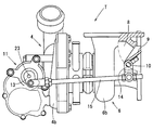
- FIG. 2 is an explanatory diagram of a turbocharger according to an embodiment of the present disclosure.
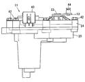
- FIG. 3 is a top view of the electric actuator according to the embodiment of the present disclosure.
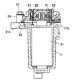
- FIG. 4 is a side view of an electric actuator according to an embodiment of the present disclosure.
- FIG. 5 is a bottom view of the electric actuator according to the embodiment of the present disclosure.
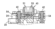
- 6 is a cross-sectional view taken along line VI-VI in FIG. 7 is a cross-sectional view taken along line VII-VII in FIG. 8 is a cross-sectional view taken along line VIII-VIII in FIG.
- FIG. 9 is a cross-sectional view taken along line IX-IX in FIG.
- FIG. 10 is an explanatory diagram of the allowable clearance.
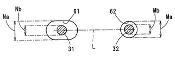
- FIG. 11 is an explanatory diagram of a recess formed in the cover.
- FIG. 12A is a perspective view of an output shaft to which a resin component constituting the final gear is fixed, and
- FIG. 12B is a perspective view of a magnetic flux generation unit molded on the resin component.
- c) is a view of the output shaft as seen from the axial direction.
- a traveling engine 1 mounted on an automobile is provided with an intake passage 2 that guides intake air into a cylinder of the engine 1 and an exhaust passage 3 that discharges exhaust gas generated in the cylinder into the atmosphere.
- an intake compressor 4 of the turbocharger T and a throttle valve 5 for adjusting the intake air amount supplied to the engine 1 are provided.
- an exhaust turbine 6 of the turbocharger T and a catalyst 7 for purifying exhaust gas are provided in the middle of the exhaust passage 3.
- the catalyst 7 is a well-known three-way catalyst that adopts a monolithic structure, and purifies harmful substances contained in the exhaust gas by oxidizing and reducing action by raising the temperature to the activation temperature.
- the exhaust turbine 6 includes a turbine wheel 6a that is rotationally driven by the exhaust gas discharged from the engine 1, and a spiral turbine housing 6b that accommodates the turbine wheel 6a.
- the intake compressor 4 includes a compressor wheel 4a that rotates in response to the rotational output of the turbine wheel 6a, and a spiral compressor housing 4b that accommodates the compressor wheel 4a.
- the turbine housing 6b is provided with a bypass passage 8 that bypasses the turbine wheel 6a and flows exhaust gas.
- the bypass passage 8 guides the exhaust gas flowing into the turbine housing 6b directly to the exhaust outlet of the turbine housing 6b.
- the bypass passage 8 is provided so as to be opened and closed by a waste gate valve 9.
- the wastegate valve 9 is a swing valve that is rotatably supported inside the turbine housing 6b. Specifically, the wastegate valve 9 is rotated through a valve shaft 10 that is rotatably supported with respect to the turbine housing 6b.
- the waste gate valve 9 controls the supercharging pressure by the turbocharger T by adjusting the opening of the bypass passage 8 when the engine 1 is rotating at high speed.
- the waste gate valve 9 warms up the catalyst 7 by fully opening the bypass passage 8 when the temperature of the catalyst 7 does not reach the activation temperature, such as immediately after a cold start. As a result, high-temperature exhaust gas that is not deprived of heat by the turbine wheel 6a can be guided to the catalyst 7, and the catalyst 7 can be warmed up early.
- the turbocharger T includes an electric actuator 11 as means for rotating the wastegate valve 9.
- the electric actuator 11 is energized and controlled by an ECU 12 that performs engine control.
- the electric actuator 11 is mounted on the intake compressor 4 away from the exhaust turbine 6 for the purpose of avoiding the thermal effect of the exhaust gas.
- the electric actuator 11 is mounted at a position away from the waste gate valve 9.
- the turbocharger T is provided with a link mechanism for transmitting the output of the electric actuator 11 to the wastegate valve 9.
- the link mechanism is a so-called four-joint link, and an actuator lever 13 that is rotated by the electric actuator 11, a valve lever 14 that is coupled to the valve shaft 10, and a rotational torque applied to the actuator lever 13 is a valve lever. 14 and a rod 15 to be transmitted to 14.
- the electric actuator 11 will be described.
- the electric actuator 11 includes a housing 20 attached to the intake compressor 4, an electric motor 21, a gear reducer 22, an output shaft 23, a cover 24, and an actuator lever 13 fixed to the tip of the output shaft 23. And is configured.
- the housing 20 includes an opening ⁇ that opens toward one side.
- reference numeral 20 a shown in FIG. 3 is a bolt insertion hole used when the electric actuator 11 is assembled to the intake compressor 4.
- the housing 20 is made of, for example, die-cast aluminum.
- a cover 24 is attached to the upper portion of the housing 20.
- the electric motor 21 converts electric power into rotational output, and is assembled to the housing 20. Specifically, the electric motor 21 is inserted into a motor insertion chamber ⁇ formed in the housing 20 and then fixed to the housing 20 with a screw or the like.
- the type or the like of the electric motor 21 is not limited. For example, a known DC motor or a known stepping motor may be used.
- the gear reducer 22 is assembled to the housing 20.
- the gear reducer 22 is a parallel shaft type having three or more speed reduction stages for reducing the rotational output generated by the electric motor 21.
- the gear reducer 22 of this embodiment has three speed reduction stages, a pinion gear 26 driven by the electric motor 21, and a first intermediate gear 27 rotated by the pinion gear 26.
- the second intermediate gear 28 is rotationally driven by the first intermediate gear 27, and the final gear 29 is rotationally driven by the second intermediate gear 28.
- the pinion gear 26 is a small-diameter external gear fixed to the rotating shaft of the electric motor 21.
- the first intermediate gear 27 is a double gear in which a first large-diameter gear 27a and a first small-diameter gear 27b are provided concentrically.
- the first intermediate gear 27 is rotatably supported by a first intermediate shaft 31 that is fixed to the housing 20.
- the pinion gear 26 and the first large-diameter gear 27a mesh with each other to form a first reduction gear.
- press-fitting is employed as a technique for fixing the first intermediate shaft 31 to the housing 20.
- the second intermediate gear 28 is a double gear in which a second large diameter gear 28a and a second small diameter gear 28b are provided concentrically.
- the second intermediate gear 28 is rotatably supported by a second intermediate shaft 32 that is fixed to the housing 20.
- the first small-diameter gear 27b and the second large-diameter gear 28a mesh with each other to form a second reduction stage.
- press-fitting is adopted as a technique for fixing the second intermediate shaft 32 to the housing 20.
- the final gear 29 is a large-diameter external gear fixed to the output shaft 23.
- the final gear 29 is provided only in a predetermined rotation range.
- the 2nd small diameter gear 28b and the last gear 29 mesh, and the 3rd speed reduction stage is comprised.
- the output shaft 23 is provided with the final gear 29 as described above. For this reason, the output shaft 23 is driven by the rotational output decelerated by the gear reducer 22.
- the cover 24 is assembled to the housing 20. As described above, a space ⁇ for accommodating the electric motor 21 and the gear reducer 22 is formed between the housing 20 and the cover 24. Further, the upper part of the output shaft 23 passes through the cover 24, and the upper end of the output shaft 23 is exposed to the outside of the cover 24.
- the cover 24 is provided by a resin material. And the resin material which comprises the cover 24 forms the connector 43 for connecting with an external apparatus while molding the motor terminal 51 which provides electric power to the electric motor 21.
- FIG. 1 A resin material which comprises the cover 24 forms the connector 43 for connecting with an external apparatus while molding the motor terminal 51 which provides electric power to the electric motor 21.
- the cover 24 is connected to the energizing terminal 21 b of the electric motor 21 to make an electrical connection, the base of the magnetic detection unit 37, and the magnetic detection unit. 37, a sensor terminal 53 electrically connected to the housing 37, a plurality of metal collars 54 through which bolts 42 for fixing the cover 24 to the housing 20 are inserted, and a metal bearing into which the cover side bearing 34 is press-fitted.
- the holder 55 is molded.
- the actuator lever 13 is fixed to the upper end of the output shaft 23 exposed at the upper part of the cover 24.
- the fixing technique of the output shaft 23 and the actuator lever 13 is not limited, but is fixed by caulking or welding.
- a pin 44 parallel to the output shaft 23 is provided at the rotating end of the actuator lever 13.
- the pin 44 is a part that is rotatably connected to the end of the rod 15 and transmits the rotational torque of the actuator lever 13 to the rod 15.
- the electric actuator 11 includes a rotation angle sensor 35 that detects the opening degree of the wastegate valve 9 by detecting the rotation angle of the output shaft 23.
- the rotation angle sensor 35 is a non-contact type, and is a magnetic flux generator 36 that rotates integrally with the output shaft 23, and a magnet that is attached to one of the cover 24 or the housing 20 and detects the magnetic flux generated by the magnetic flux generator 36. And a detection unit 37. Then, the rotation angle of the output shaft 23 detected by the rotation angle sensor 35 is output to the ECU 12. The details of the rotation angle sensor 35 will be described later.
- the ECU 12 is an engine control unit in which a microcomputer is mounted, and includes a control program for controlling energization of the electric actuator 11.
- the ECU 12 calculates the target opening degree of the wastegate valve 9 suitable for the operating state of the engine 1 from the operating state of the engine 1. Then, the electric actuator 11 is feedback controlled so that the calculated target opening and the detected opening detected by the rotation angle sensor 35 coincide.
- this supercharging pressure control is an example, and is not limited.
- the ECU 12 performs an early warm-up of the catalyst 7 when the actual temperature or the predicted temperature of the catalyst 7 has not reached the activation temperature, such as immediately after a cold start. Specifically, the ECU 12 sets the wastegate valve 9 to a predetermined opening when the catalyst 7 is warmed up early. Thereby, it is possible to prevent the heat of the exhaust gas from being taken away by the wastegate valve 9.
- the early warm-up control of the catalyst 7 is an example, and is not limited.
- the housing 20 includes a housing end surface 20b with which the cover 24 contacts.
- the housing end surface 20b is provided on a plane perpendicular to the axial direction.
- the cover 24 includes a cover end surface 24 b that contacts the housing 20.
- the cover end surface 24b is also provided on a plane perpendicular to the axial direction.
- the cover 24 is positioned with respect to the housing 20.
- the cover 24 is fixed to the housing 20 with a plurality of bolts 42 in a state where the positioning is achieved.
- a housing side bearing 33 that rotatably supports the output shaft 23 with respect to the housing 20 is disposed.
- a cover-side bearing 34 that rotatably supports the output shaft 23 with respect to the cover 24 is disposed between the cover 24 and the output shaft 23.
- the housing side bearing 33 and the cover side bearing 34 may be rolling bearings such as ball bearings or roller bearings, or may be sliding bearings such as metal bearings.
- a ball bearing employs a well-known structure having a rubber seal. That is, a structure is adopted in which a plurality of balls are arranged between the outer outer race and the inner inner race.
- the outer peripheral surface of the housing side bearing 33 is press-fitted into the housing 20. Further, the lower side of the output shaft 23 is press-fitted into the inner peripheral surface of the housing side bearing 33.
- the outer peripheral surface of the cover side bearing 34 is press-fitted into the cover 24.
- the cover 24 is provided by a resin material.
- a metal bearing holder 55 is molded in the cover 24 in order to press-fit the cover-side bearing 34.
- the outer peripheral surface of the cover-side bearing 34 is press-fitted into the bearing holder 55. Further, the upper side of the output shaft 23 is press-fitted into the inner peripheral surface of the cover-side bearing 34.
- the output shaft 23 is rotatably supported.
- the gear reducer 22 includes a first intermediate shaft 31 and a second intermediate shaft 32 that are parallel to the output shaft 23.
- first intermediate shaft 31 is press-fitted into the housing 20.
- second intermediate shaft 32 is also press-fitted into the housing 20.
- first intermediate shaft 31 and the second intermediate shaft 32 are press-fitted into a first press-fitting hole 39 and a second press-fitting hole 40 formed on the bottom surface inside the opening ⁇ .
- the upper end of the first intermediate shaft 31 is fitted inside the first recess 61 formed in the cover 24.
- the upper part of the second intermediate shaft 32 is fitted inside the second recess 62 formed in the cover 24.
- the first recess 61 and the second recess 62 are recessed portions that open downward on the lower surface of the cover 24, and are formed at the same time as the cover 24 is molded.
- the positioning of the cover 24 with respect to the housing 20 is performed by fitting the other ends of the plurality of intermediate shafts with the plurality of recesses.
- the positioning of the cover 24 with respect to the housing 20 is performed in two places: “fitting the first intermediate shaft 31 and the first recess 61” and “fitting the second intermediate shaft 32 and the second recess 62”.
- the fitting of the first intermediate shaft 31 and the first recess 61 is referred to as a first fitting
- the fitting of the second intermediate shaft 32 and the second recess 62 is referred to as a second fitting. To do.
- the range in which the housing end surface 20b and the cover end surface 24b can slide is regulated by the first fitting and the second fitting.
- the clearance x is provided between the outer race and the inner race.
- a clearance x is provided between the cover-side bearing 34 and the output shaft 23 as shown in FIG.
- FIG. 10 shows a state in which the output shaft 23 is inclined due to a deviation of the assembly of the cover 24 with respect to the housing 20, that is, a deviation of the assembly of the housing side bearing 33 and the cover side bearing 34 in the radial direction. 10 indicates the axial direction when the output shaft 23 is assembled to the housing 20 without being inclined. In addition, an alternate long and short dash line y2 in FIG. 10 indicates the axial direction of the output shaft 23 in an inclined state.
- the cover 24 for the housing 20 is formed by “fitting the first intermediate shaft 31 and the first recess 61” and “fitting the second intermediate shaft 32 and the second recess 62”. Positioning is performed.
- the cover 24 when the cover 24 is fixed to the housing 20, a load applied when the cover 24 is assembled is prevented from being transmitted to the output shaft 23 via the cover side bearing 34 and the housing side bearing 33. it can. That is, the cover 24 and the housing 20 can be positioned so that the clearance x> 0 (zero).
- clearance x 0 (zero)
- the load transmitted to the output shaft 23 via the cover-side bearing 34 and the housing-side bearing 33 can be reduced to an allowable load or less. For this reason, clearance x ⁇ 0 (zero) may be satisfied.
- the second intermediate shaft 32 is used for positioning.
- one of the first recess 61 or the second recess 62 is provided in the round hole.
- the other of the first recess 61 and the second recess 62 is provided in the long hole.
- the longitudinal direction of a long hole (refer 1st recessed part 61) is provided along the straight line L which goes to a round hole (refer 2nd recessed part 62) from a long hole.
- the round hole and the long hole are hole shapes of the first recess 61 and the second recess 62 when the cover 24 is viewed from the lower surface.
- the round hole has a perfect hole shape.
- the long hole has a hole shape in which ends of arcs obtained by dividing a perfect circle into two are connected by parallel straight lines.
- the inner diameter dimension Ma of the round hole is slightly larger than the outer diameter dimension Mb of the intermediate shaft fitted into the round hole.
- the intermediate shaft that fits into the round hole is the second intermediate shaft 32.
- the inner diameter dimension Ma of the round hole is slightly larger than the outer diameter dimension Mb of the second intermediate shaft 32.
- the inner diameter dimension Na perpendicular to the longitudinal direction of the elongated hole is set slightly larger than the outer diameter dimension Nb of the intermediate shaft fitted in the elongated hole.
- the intermediate shaft that fits into the elongated hole is the first intermediate shaft 31.
- the inner diameter dimension Na in the direction perpendicular to the longitudinal direction of the elongated hole is slightly larger than the outer diameter dimension Nb of the first intermediate shaft 31.
- the round hole is provided in a recess that fits into the intermediate shaft that is closest to the output shaft 23 among the plurality of intermediate shafts.
- the second recess 62 is provided with a round hole, and the first recess 61 is provided in the elongated hole.
- the electric actuator 11 includes a rotation angle sensor 35 that detects the rotation angle of the output shaft 23.
- the rotation angle sensor 35 includes a magnetic flux generator 36 that rotates integrally with the output shaft 23, and a magnetic detector 37 that is attached to one of the cover 24 or the housing 20 and detects the magnetic flux generated by the magnetic flux generator 36. Prepare. In this embodiment, an example in which the magnetic detection unit 37 is provided on the cover 24 is shown.
- a gear range ⁇ 1 where the final gear 29 of the gear reducer 22 is provided and a detection range ⁇ 2 where the magnetic flux generator 36 is provided are provided separately. That is, the gear range ⁇ 1 and the detection range ⁇ 2 are provided so as not to overlap when the output shaft 23 is viewed from the axial direction.
- the opening degree of the wastegate valve can be read based on the rotation angle of the output shaft 23 detected by the rotation angle sensor 35.
- Rotation angle sensor 35 is disposed at a position off the axis of output shaft 23. Thereby, the rotation angle sensor 35 does not have to be disposed at the shaft end of the output shaft 23. Thereby, the axial direction of the electric actuator 11 can be shortened.
- the magnetic flux generator 36 is arranged using a rotation space where the final gear 29 is not provided. Thereby, size reduction of the electric actuator 11 is attained. And the mounting property with respect to the intake compressor 4 can be improved by size reduction of the electric actuator 11.
- the magnetic flux generator 36 is molded on a resin part that forms the final gear, and forms a closed magnetic path by combining two permanent magnets 71 and two magnetic metal yokes 72.
- the two yokes 72 are provided by combining two yokes 72 having arc shapes with different curvature radii.
- the type of the permanent magnet 71 is not limited, and may be, for example, a rare earth magnet or a ferrite magnet.
- the two yokes 72 are iron parts having arc shapes with different curvature radii.
- the two yokes 72 sandwich the permanent magnets 71 one by one at both ends thereof.
- an arcuate arc gap ⁇ into which the magnetic detection unit 37 is inserted is formed.
- This arc gap ⁇ is an arc concentric with the axis center of the output shaft 23.
- the opposing width of the two yokes 72 is fixed in the radial direction.
- the arc gap ⁇ is provided so as to maintain a non-contact state with respect to the magnetic detection unit 37 even when the magnetic flux generation unit 36 rotates as the output shaft 23 rotates.
- the poles of the two permanent magnets 71 are arranged in reverse. Specifically, in one permanent magnet 71, the south pole is disposed toward the output shaft 23. Further, the other permanent magnet 71 is arranged such that the N pole faces the output shaft 23. By providing in this way, a closed magnetic path through which the magnetic flux passes through one permanent magnet 71 ⁇ the outer yoke 72 ⁇ the other permanent magnet 71 ⁇ the inner yoke 72 is formed.
- a part of the magnetic flux generated in the magnetic flux generation unit 36 passes through the magnetic detection unit 37 inserted in the arc gap ⁇ . Specifically, a part of the magnetic flux of one yoke 72 flows to the other yoke 72 via the magnetic detection unit 37.
- the magnetic detection unit 37 is provided with a Hall IC that generates a signal corresponding to the magnetic flux passing therethrough. For this reason, when the magnetic flux generation unit 36 rotates as the output shaft 23 rotates, the amount of magnetic flux passing through the Hall IC changes, and the signal of the magnetic detection unit 37 changes. Then, the ECU 12 reads the angle of the output shaft 23 from the signal input from the magnetic detection unit 37.
- the cover 24 is provided by a resin material.
- the resin material forming the cover 24 is molded with the magnetic detection unit 37.
- the electric actuator 11 which drives the wastegate valve 9 was illustrated, the drive target object of the electric actuator 11 is not limited to the wastegate valve 9.
- the parallel shaft type gear reducer 22 having three speed reduction stages is shown.
- the speed reduction stage is not limited to three stages, and may be four stages or more. That is, three or more intermediate shafts may be provided.
- the shape of the 1st recessed part 61 and the 2nd recessed part 62 is not limited to these shapes, You may make it into arbitrary shapes as needed.
- the first recess 61 is long as long as the inner peripheral wall of the first recess 61 abuts on the first intermediate shaft 31 and the rotation of the cover 24 around the second intermediate shaft 32 can be suppressed.
Landscapes
- Engineering & Computer Science (AREA)
- General Engineering & Computer Science (AREA)
- Mechanical Engineering (AREA)
- Power Engineering (AREA)
- Chemical & Material Sciences (AREA)
- Combustion & Propulsion (AREA)
- Microelectronics & Electronic Packaging (AREA)
- Connection Of Motors, Electrical Generators, Mechanical Devices, And The Like (AREA)
- Gear Transmission (AREA)
- General Details Of Gearings (AREA)
- Supercharger (AREA)
Abstract
ハウジング(20)に対するカバー(24)の位置決めは、「第1中間シャフト(31)と第1凹部(61)の嵌合」と「第2中間シャフト(32)と第2凹部(62)の嵌合」の2箇所で成される。これにより、カバー(24)の負荷がカバー側軸受(34)を介して出力シャフト(23)に伝わらない。このため、カバー(24)がハウジング(20)に固定された状態において、カバー側軸受(34)と出力シャフト(23)の間、およびハウジング側軸受(33)と出力シャフト(23)の間に、過大な荷重が発生することがない。
Description
本願は、2015年6月18日に出願された日本国特許出願第2015-123102号に基づくものであり、この開示をもってその内容を本明細書中に開示したものとする。
本開示は、出力シャフトを回動操作する電動アクチュエータに関する。
出力シャフトを回動操作する電動アクチュエータの一例として、特許文献1に開示される技術が知られている。
この特許文献1の電動アクチュエータは、電動モータが発生する回転出力を平行軸式の歯車減速機で減速して出力シャフトを駆動する。歯車減速機は、出力シャフトと平行な中間シャフトを備える。この中間シャフトは、ハウジングに支持される。
一方、出力シャフトの一端は、ハウジングと出力シャフトの間に配置される軸受(以下、ハウジング側軸受と称す)によって回転自在に支持される。
また、出力シャフトの他端は、カバーと出力シャフトの間に配置される軸受(以下、カバー側軸受と称す)によって回転自在に支持される。
特許文献1の電動アクチュエータは、出力シャフトと中間シャフトを用いてハウジングに対するカバーの位置決めを行っている。
このため、カバーをハウジングに組付ける際、カバー側軸受と出力シャフトの隙間、およびハウジング側軸受と出力シャフトの隙間を管理することができない。このため、カバー側軸受と出力シャフトの間、およびハウジング側軸受と出力シャフトの間に、隙間が存在しない状態で組み付くことで、出力シャフトに過大な荷重が加えられた状態で、カバーがハウジングに固定される可能性がある。
カバー側軸受が出力シャフトに過大な荷重で押し付けられるとともに、ハウジング側軸受が出力シャフトに過大な荷重で押し付けられた状態で、出力シャフトが回動すると、カバー側軸受、ハウジング側軸受、出力シャフトに摩耗等の損傷が生じる懸念がある。具体的には、電動アクチュエータの作動不良や異音の発生に繋がる懸念が生じる。
本開示の目的は、カバーがハウジングに固定された状態において、カバー側軸受と出力シャフトの間、およびハウジング側軸受と出力シャフトの間に、過大な荷重が発生することのない電動アクチュエータの提供にある。
上記の目的を達成するために、本開示では、電動モータ、ハウジング、平行軸式の歯車減速機、出力シャフト、カバー、ハウジング側軸受およびカバー側軸受を備える電動アクチュエータを提供する。電動モータは、電力を回転出力に変換する。ハウジングには、電動モータが固定される。歯車減速機は、電動モータの発生する回転出力を減速する。出力シャフトは、歯車減速機によって減速された回転出力により駆動される。カバーは、ハウジングに組み付けられ、ハウジングとの間に電動モータと歯車減速機を収容する空間を形成する。ハウジング側軸受は、ハウジングと出力シャフトの間に配置されて、ハウジングに対して出力シャフトを回転自在に支持する。カバー側軸受は、カバーと出力シャフトの間に配置されて、カバーに対して出力シャフトを回転自在に支持する。歯車減速機は、出力シャフトに平行な複数の中間シャフトを備え、複数の中間シャフトの一端は、ハウジングに固定され、複数の前記中間シャフトの他端は、カバーに形成された複数の凹部の内側に嵌め入れられる。複数の中間シャフトの他端と、複数の凹部との嵌合によって、ハウジングに対するカバーの位置決めが成される。
上記の構成では、複数の中間シャフトと、カバーに設けた複数の凹部との嵌合によって、ハウジングに対するカバーの位置決めが成される。
このため、出力シャフトがカバーの位置決めに用いられない。その結果、出力シャフトに位置決めの荷重が作用しない。これにより、カバーがハウジングに固定された状態において、カバー側軸受と出力シャフトの間、およびハウジング側軸受と出力シャフトの間に、過大な荷重が発生しない。
以下では、図面に基づいて本開示を実施するための形態を説明する。なお、以下で開示する実施形態は、一例を開示するものであって、本開示が実施形態に限定されないことは言うまでもない。
[実施形態1]
図1~図12(c)に基づいて実施形態1を説明する。
図1~図12(c)に基づいて実施形態1を説明する。
自動車に搭載される走行用のエンジン1には、吸気をエンジン1の気筒内へ導く吸気通路2と、気筒内で発生した排気ガスを大気中に排出する排気通路3とが設けられる。
吸気通路2の途中には、ターボチャージャTの吸気コンプレッサ4と、エンジン1に供給される吸気量の調整を行うスロットルバルブ5とが設けられる。
排気通路3の途中には、ターボチャージャTの排気タービン6と、排気ガスの浄化を行う触媒7とが設けられる。なお、触媒7はモノリス構造を採用する周知な三元触媒であり、活性化温度に昇温することで排気ガス中に含まれる有害物質を酸化作用と還元作用により浄化する。
排気タービン6は、エンジン1から排出された排気ガスによって回転駆動されるタービンホイール6aと、このタービンホイール6aを収容する渦巻形状のタービンハウジング6bとを備える。
吸気コンプレッサ4は、タービンホイール6aの回転出力を受けて回転するコンプレッサホイール4aと、このコンプレッサホイール4aを収容する渦巻形状のコンプレッサハウジング4bとを備える。
タービンハウジング6bには、タービンホイール6aを迂回して排気ガスを流すバイパス通路8が設けられる。
バイパス通路8は、タービンハウジング6bに流入した排気ガスを直接タービンハウジング6bの排気出口へ導く。このバイパス通路8は、ウエストゲートバルブ9によって開閉可能に設けられる。
ウエストゲートバルブ9は、タービンハウジング6bの内部で回動可能に支持されるスイングバルブである。具体的に、ウエストゲートバルブ9は、タービンハウジング6bに対して回転自在に支持されるバルブ軸10を介して回動操作される。
このウエストゲートバルブ9は、エンジン1の高回転時などに、バイパス通路8の開度を調整してターボチャージャTによる過給圧をコントロールする。
また、ウエストゲートバルブ9は、冷間始動直後など、触媒7の温度が活性化温度に達していない時に、バイパス通路8を全開にして触媒7の暖機を行う。これにより、タービンホイール6aに熱を奪われていない高温の排気ガスを触媒7へ導くことができ、触媒7の早期暖機を実施できる。
ウエストゲートバルブ9を回動操作する手段として、ターボチャージャTは、電動アクチュエータ11を備える。この電動アクチュエータ11は、エンジン制御を行うECU12によって通電制御される。
電動アクチュエータ11は、排気ガスの熱影響を回避する目的で、排気タービン6から離れた吸気コンプレッサ4に搭載される。このように、電動アクチュエータ11は、ウエストゲートバルブ9から離れた位置に搭載される。このため、ターボチャージャTには、電動アクチュエータ11の出力をウエストゲートバルブ9に伝達するためのリンク機構が設けられる。
リンク機構は、所謂4節リンクであり、電動アクチュエータ11によって回動操作されるアクチュエータレバー13と、バルブ軸10に結合されるバルブレバー14と、アクチュエータレバー13に付与される回動トルクをバルブレバー14に伝えるロッド15とを備える。
電動アクチュエータ11を説明する。
電動アクチュエータ11は、吸気コンプレッサ4に取り付けられるハウジング20と、このハウジング20に組み付けられる電動モータ21、歯車減速機22、出力シャフト23、カバー24と、出力シャフト23の先端に固定されるアクチュエータレバー13とを備えて構成される。
ハウジング20は、一方に向けて開口する開口部αを備える。
以下では、説明の便宜上、ハウジング20において開口部αが開口する方向を上、逆方向を下として説明する。もちろん、この上下方向は、搭載方向を限定するものではない。なお、図3に示す符合20aは、電動アクチュエータ11を吸気コンプレッサ4に組付ける際に用いられるボルト挿通穴である。
ハウジング20は、例えばアルミニウム等によるダイキャスト製である。このハウジング20の上部には、カバー24が装着される。
そして、ハウジング20とカバー24との間に形成される空間βに、電動モータ21や歯車減速機22等が配置される。
電動モータ21は、電力を回転出力に変換するものであり、ハウジング20に組み付けられる。具体的に電動モータ21は、ハウジング20に形成されたモータ挿入室γに挿入された後、スクリュ等によってハウジング20に固定される。電動モータ21の型式等は限定するものではなく、例えば周知の直流モータであっても良いし、周知のステッピングモータであっても良い。
歯車減速機22は、ハウジング20に組み付けられるものである。この歯車減速機22は、電動モータ21の発生する回転出力を減速する減速段が3段以上の平行軸式である。
具体的に、この実施形態の歯車減速機22は、3段の減速段を有するものであり、電動モータ21によって駆動されるピニオンギヤ26と、このピニオンギヤ26によって回転駆動される第1中間ギヤ27と、この第1中間ギヤ27によって回転駆動される第2中間ギヤ28と、この第2中間ギヤ28によって回転駆動される最終ギヤ29とを備える。
ピニオンギヤ26は、電動モータ21の回転軸に固定された小径の外歯歯車である。
第1中間ギヤ27は、第1大径ギヤ27aと第1小径ギヤ27bが同芯で設けられた2重歯車である。この第1中間ギヤ27は、ハウジング20に固定される第1中間シャフト31によって回転自在に支持される。そして、ピニオンギヤ26と第1大径ギヤ27aが噛合して1段目の減速段が構成される。なお、ハウジング20に対する第1中間シャフト31の固定技術として、この実施形態では圧入を採用している。
第2中間ギヤ28は、第1中間ギヤ27と同様、第2大径ギヤ28aと第2小径ギヤ28bが同芯で設けられた2重歯車である。この第2中間ギヤ28は、ハウジング20に固定される第2中間シャフト32によって回転自在に支持される。そして、第1小径ギヤ27bと第2大径ギヤ28aが噛合して2段目の減速段が構成される。なお、ハウジング20に対する第2中間シャフト32の固定技術として、この実施形態では圧入を採用している。
最終ギヤ29は、出力シャフト23に固定された大径の外歯歯車である。この最終ギヤ29は、所定の回動範囲のみに設けられる。そして、第2小径ギヤ28bと最終ギヤ29が噛合して3段目の減速段が構成される。
出力シャフト23には、上述したように最終ギヤ29が設けられている。このため、出力シャフト23は、歯車減速機22によって減速された回転出力により駆動される。
カバー24は、ハウジング20に組み付けられる。そして、上述したようにハウジング20とカバー24の間には、電動モータ21や歯車減速機22を収容する空間βが形成される。また、カバー24は、出力シャフト23の上部が貫通するものであり、出力シャフト23の上端がカバー24の外部に露出する。
カバー24は、樹脂材料によって設けられる。そして、カバー24を成す樹脂材料は、電動モータ21に電力を付与するモータターミナル51をモールドするとともに、外部機器との接続を行うためのコネクタ43を形成する。
具体的に、カバー24は、モータターミナル51の他に、電動モータ21の通電端子21bと結合して電気的な接続を行う中継ターミナル52と、磁気検出部37の根元部と、この磁気検出部37に電気的に接続されるセンサターミナル53と、カバー24をハウジング20に固定するためのボルト42が挿通される複数の金属製のカラー54と、カバー側軸受34が圧入される金属製のベアリングホルダ55とがモールドされる。
アクチュエータレバー13は、カバー24の上部に露出した出力シャフト23の上端に固定される。なお、出力シャフト23とアクチュエータレバー13の固定技術は限定するものではないが、カシメまたは溶接により固定される。
アクチュエータレバー13の回動端には、出力シャフト23と平行なピン44が設けられる。このピン44は、ロッド15の端部に回動自在に連結されて、アクチュエータレバー13の回動トルクをロッド15に伝える部品である。
電動アクチュエータ11は、出力シャフト23の回転角度を検出することでウエストゲートバルブ9の開度を検出する回転角センサ35を備える。
回転角センサ35は、非接触型であり、出力シャフト23と一体に回動する磁束発生部36と、カバー24またはハウジング20の一方に取り付けられて磁束発生部36の発生する磁束を検出する磁気検出部37とを備える。そして、回転角センサ35によって検出される出力シャフト23の回転角度は、ECU12へ出力される。なお、この回転角センサ35の詳細は後述する。
ECU12は、マイクロコンピュータを搭載するエンジン・コントロール・ユニットであり、電動アクチュエータ11を通電制御する制御プログラムを備える。
具体的に、ECU12は、エンジン1の運転状態からエンジン1の運転状態に適したウエストゲートバルブ9の目標開度を算出する。そして、算出した目標開度と回転角センサ35によって検出した検出開度とが一致するように電動アクチュエータ11をフィードバック制御する。もちろん、この過給圧制御は一例であり、限定するものではない。
また、ECU12は、冷間始動直後など、触媒7の実温度または予測温度が活性化温度に達していない時に、触媒7の早期暖機を実施する。具体的に、ECU12は、触媒7の早期暖機を行う際に、ウエストゲートバルブ9を所定の開度に設定する。これにより、排気ガスの熱がウエストゲートバルブ9に奪われるのを防ぐことができる。もちろん、この触媒7の早期暖機制御は一例であり、限定するものではない。
(特徴技術1)
以下では、出力シャフト23、第1中間シャフト31、第2中間シャフト32の各軸芯が伸びる方向を軸方向と称する。
以下では、出力シャフト23、第1中間シャフト31、第2中間シャフト32の各軸芯が伸びる方向を軸方向と称する。
ハウジング20は、カバー24が接するハウジング端面20bを備える。このハウジング端面20bは、軸方向に対して垂直な平面に設けられる。
同様に、カバー24は、ハウジング20と接するカバー端面24bを備える。このカバー端面24bも軸方向に対して垂直な平面に設けられる。
カバー24は、ハウジング20に対して位置決めが成されている。そして、位置決めが成された状態でカバー24は、複数のボルト42によってハウジング20に固定されている。
以下では、ハウジング20に対するカバー24の位置決め構造を説明する。
ハウジング20と出力シャフト23の間には、ハウジング20に対して出力シャフト23を回転自在に支持するハウジング側軸受33が配置される。
また、カバー24と出力シャフト23の間には、カバー24に対して出力シャフト23を回転自在に支持するカバー側軸受34が配置される。
ハウジング側軸受33およびカバー側軸受34は、ボールベアリングやローラベアリング等の転がり軸受であっても良いし、メタルベアリング等の滑り軸受であっても良い。なお、この実施形態では、ボールベアリングを採用するものとして説明する。このボールベアリングは、ゴムシールを有する周知な構造を採用する。即ち、外側のアウターレースと、内側のインナーレースとの間に複数のボールが配置される構造を採用する。
ハウジング側軸受33の外周面は、ハウジング20に圧入される。また、出力シャフト23の下側は、ハウジング側軸受33の内周面に圧入される。
カバー側軸受34の外周面は、カバー24に圧入される。具体的に、カバー24は、樹脂材料によって設けられる。このため、カバー24には、カバー側軸受34を圧入するために金属製のベアリングホルダ55がモールドされている。そして、カバー側軸受34の外周面は、ベアリングホルダ55に圧入される。また、出力シャフト23の上側は、カバー側軸受34の内周面に圧入される。
このように設けることで、出力シャフト23が回転自在に支持される。
歯車減速機22は、出力シャフト23に平行な第1中間シャフト31と第2中間シャフト32を備える。
第1中間シャフト31の下端はハウジング20に圧入される。同様に、第2中間シャフト32の下端もハウジング20に圧入される。具体的に、第1中間シャフト31と第2中間シャフト32は、開口部αの内側の底面に形成された第1圧入穴39と第2圧入穴40に圧入される。
第1中間シャフト31の上端は、カバー24に形成される第1凹部61の内側に嵌め入れられる。同様に、第2中間シャフト32の上方は、カバー24に形成される第2凹部62の内側に嵌め入れられる。なお、第1凹部61と第2凹部62は、カバー24の下面において下方に向かって開口する窪み部であり、カバー24の成形時に同時に形成されるものである。
ハウジング20に対するカバー24の位置決めは、複数の中間シャフトの他端と、複数の凹部との嵌合によって成される。
即ち、ハウジング20に対するカバー24の位置決めは、「第1中間シャフト31と第1凹部61の嵌合」と「第2中間シャフト32と第2凹部62の嵌合」の2箇所で成される。
以下では、「第1中間シャフト31と第1凹部61の嵌合」を第1嵌合と称し、「第2中間シャフト32と第2凹部62の嵌合」を第2嵌合と称して説明する。
第1嵌合と第2嵌合がなされた状態では、ハウジング端面20bとカバー端面24bを摺動できる範囲は、第1嵌合と第2嵌合によって規制される。
そして、第1嵌合と第2嵌合がなされた状態では、ハウジング端面20bに対してカバー端面24bをどの方向に摺動させても、カバー24の負荷が出力シャフト23に与えられないように設けられている。即ち、この実施形態では、カバー24の組付負荷が出力シャフト23に伝わるのを防ぐクリアランスxが設けられる。
この実施形態のように、カバー側軸受34がボールベアリングの場合、クリアランスxはアウターレースとインナーレースの間に設けられる。
また、この実施形態とは異なり、カバー側軸受34がメタルベアリングの場合は、図10に示すように、カバー側軸受34と出力シャフト23の間にクリアランスxが設けられる。
なお、図10は、ハウジング20に対するカバー24の組付けのズレ、即ちハウジング側軸受33とカバー側軸受34の径方向の組付けのズレによって出力シャフト23が傾斜した状態を示す。そして、図10中の一点鎖線y1は、ハウジング20に対して出力シャフト23が傾くことなく組み付けられた場合の軸方向を示す。また、図10中の一点鎖線y2は、傾斜した状態の出力シャフト23の軸方向を示す。
(効果)
この実施形態では、上述したように、「第1中間シャフト31と第1凹部61の嵌合」と、「第2中間シャフト32と第2凹部62の嵌合」とにより、ハウジング20に対するカバー24の位置決めが成される。
この実施形態では、上述したように、「第1中間シャフト31と第1凹部61の嵌合」と、「第2中間シャフト32と第2凹部62の嵌合」とにより、ハウジング20に対するカバー24の位置決めが成される。
これにより、カバー24がハウジング20に固定された状態であれば、カバー24を組付ける際に加えられた負荷が、カバー側軸受34およびハウジング側軸受33を介して出力シャフト23に伝わらないようにできる。即ち、クリアランスx>0(ゼロ)となるようにカバー24とハウジング20の位置決めをすることができる。
なお、クリアランスx=0(ゼロ)であっても、カバー側軸受34およびハウジング側軸受33を介して出力シャフト23に伝わる荷重を許容荷重以下にできる。このため、クリアランスx≧0(ゼロ)であれば良い。
このように、カバー24がハウジング20に固定された状態において、カバー側軸受34と出力シャフト23の間、およびハウジング側軸受33と出力シャフト23の間に、過大な荷重が発生しない。
(特徴技術2)
ハウジング20に対するカバー24の位置決めは、複数の中間シャフトのうちで最も出力シャフト23に近い中間シャフトを用いる。
ハウジング20に対するカバー24の位置決めは、複数の中間シャフトのうちで最も出力シャフト23に近い中間シャフトを用いる。
即ち、この実施形態では、第2中間シャフト32を位置決めに用いる。
(効果)
このように、出力シャフト23に最も近い第2中間シャフト32を用いてカバー24の位置決めを行うことで、出力シャフト23に対するカバー側軸受34の組付精度を高めることができる。
このように、出力シャフト23に最も近い第2中間シャフト32を用いてカバー24の位置決めを行うことで、出力シャフト23に対するカバー側軸受34の組付精度を高めることができる。
(特徴技術3)
この実施形態では、第1凹部61または第2凹部62の一方が丸穴に設けられる。また、第1凹部61または第2凹部62の他方が長穴に設けられる。
この実施形態では、第1凹部61または第2凹部62の一方が丸穴に設けられる。また、第1凹部61または第2凹部62の他方が長穴に設けられる。
そして、図11に示すように、長穴(第1凹部61参照)の長手方向は、長穴から丸穴(第2凹部62参照)に向かう直線Lに沿って設けられる。
なお、丸穴と長穴は、カバー24を下面から見た第1凹部61と第2凹部62の穴形状である。具体的に、丸穴は、真円の穴形状である。また、長穴は、真円を2つに分割した各円弧の端を、平行な直線で接続した穴形状である。
丸穴の内径寸法Maは、この丸穴に嵌合する中間シャフトの外径寸法Mbより僅かに大きく設けられる。具体的に、この実施形態では、丸穴に嵌合する中間シャフトは第2中間シャフト32である。このため、丸穴の内径寸法Maは、第2中間シャフト32の外径寸法Mbより僅かに大きく設けられる。
一方、長穴における長手方向に対して垂直方向の内径寸法Naは、この長穴に嵌合する中間シャフトの外径寸法Nbより僅かに大きく設けられる。具体的に、この実施形態では、長穴に嵌合する中間シャフトは第1中間シャフト31である。このため、長穴における長手方向に対して垂直方向の内径寸法Naは、第1中間シャフト31の外径寸法Nbより僅かに大きく設けられる。
(効果)
丸穴によってハウジング20に対するカバー24の基準位置が規制される。また、長穴によって丸穴を中心としたカバー24の回転方向の位置が規制される。このように、長穴は、回転方向の規制のみを行う。このため、長穴の長手方向の公差を大きくすることができる。
丸穴によってハウジング20に対するカバー24の基準位置が規制される。また、長穴によって丸穴を中心としたカバー24の回転方向の位置が規制される。このように、長穴は、回転方向の規制のみを行う。このため、長穴の長手方向の公差を大きくすることができる。
(特徴技術4)
丸穴は、複数の中間シャフトのうちで最も出力シャフト23に近い中間シャフトに嵌合する凹部に設けられる。
丸穴は、複数の中間シャフトのうちで最も出力シャフト23に近い中間シャフトに嵌合する凹部に設けられる。
即ち、この実施形態では、第2凹部62に丸穴が設けられ、第1凹部61が長穴に設けられる。
(効果)
このように、出力シャフト23に最も近い第2凹部62によってハウジング20に対するカバー24の基準位置を規制するため、出力シャフト23に対するカバー側軸受34の組付精度を高めることができる。
このように、出力シャフト23に最も近い第2凹部62によってハウジング20に対するカバー24の基準位置を規制するため、出力シャフト23に対するカバー側軸受34の組付精度を高めることができる。
(特徴技術5)
電動アクチュエータ11は、出力シャフト23の回転角度を検出する回転角センサ35を備える。
電動アクチュエータ11は、出力シャフト23の回転角度を検出する回転角センサ35を備える。
この回転角センサ35は、出力シャフト23と一体に回動する磁束発生部36と、カバー24またはハウジング20の一方に取り付けられて磁束発生部36の発生する磁束を検出する磁気検出部37とを備える。なお、この実施形態では、磁気検出部37をカバー24に設ける例を示す。
出力シャフト23の周囲には、歯車減速機22の最終ギヤ29が設けられるギヤ範囲θ1と、磁束発生部36が設けられる検出範囲θ2とが別々に設けられる。即ち、出力シャフト23を軸方向から見た場合に、ギヤ範囲θ1と検出範囲θ2が重ならないように設けられている。
(効果)
電動アクチュエータ11に機械的なロックが生じた場合には、回転角センサ35により異常を検出することができる。
電動アクチュエータ11に機械的なロックが生じた場合には、回転角センサ35により異常を検出することができる。
回転角センサ35によって検出した出力シャフト23の回転角に基づいてウエストゲートバルブの開度を読み取ることができる。
出力シャフト23の軸芯から外れた位置に回転角センサ35を配置する。これにより、出力シャフト23の軸端に回転角センサ35を配置しなくても良い。これにより、電動アクチュエータ11の軸方向の短縮が可能になる。
具体的に、この実施形態では、最終ギヤ29を設けない回動スペースを利用して磁束発生部36を配置する。これにより、電動アクチュエータ11の小型化が可能になる。そして、電動アクチュエータ11の小型化により、吸気コンプレッサ4に対する搭載性を向上できる。
(特徴技術5の関連技術)
磁束発生部36は、最終ギヤを成す樹脂部品にモールドされるものであり、2つの永久磁石71と、2つの磁性体金属製のヨーク72とを組み合わせて閉磁路を成す。2つのヨーク72は、曲率半径の異なる円弧形状を呈した2つのヨーク72を組み合わせて設けられる。
磁束発生部36は、最終ギヤを成す樹脂部品にモールドされるものであり、2つの永久磁石71と、2つの磁性体金属製のヨーク72とを組み合わせて閉磁路を成す。2つのヨーク72は、曲率半径の異なる円弧形状を呈した2つのヨーク72を組み合わせて設けられる。
永久磁石71の種類は限定するものではなく、例えば、希土類磁石であっても良いし、フェライトマグネットであっても良い。
2つのヨーク72は、曲率半径の異なる円弧形状を呈する鉄製部品である。そして、2つのヨーク72は、その両端において永久磁石71を1つずつ挟む。
2つのヨーク72の間には、磁気検出部37が挿し入れられる円弧状の円弧隙間δが形成される。この円弧隙間δは、出力シャフト23の軸中心と同芯の円弧である。2つのヨーク72の対向幅は、ラジアル方向において一定に設けられる。そして、円弧隙間δは、出力シャフト23が回動に伴って磁束発生部36が回動しても、磁気検出部37に対して非接触の状態を保つように設けられる。
2つの永久磁石71は、それぞれの極が逆に配置される。具体的に、一方の永久磁石71は、S極が出力シャフト23に向けて配置される。また、他方の永久磁石71は、N極が出力シャフト23に向けて配置される。このように設けることで、一方の永久磁石71→外側のヨーク72→他方の永久磁石71→内側のヨーク72を磁束が通る閉磁路が形成される。
磁束発生部36に生じる磁束の一部は、円弧隙間δに挿し入れられた磁気検出部37を通過する。具体的には、一方のヨーク72の磁束の一部が磁気検出部37を介して他方のヨーク72へ流れる。この磁気検出部37には、通過する磁束に応じた信号を発生するホールICが設けられる。このため、出力シャフト23の回動に伴って磁束発生部36が回動すると、ホールICを通過する磁束量が変化し、磁気検出部37の信号が変化する。そして、ECU12は、磁気検出部37から入力した信号から出力シャフト23の角度を読み取る。
(効果)
閉磁路を成す磁束発生部36を用いることにより、磁気ノイズなど外部から付与される磁気的な影響を受け難くできる。このため、回転角センサ35による出力シャフト23の検出精度を高めることができる。
閉磁路を成す磁束発生部36を用いることにより、磁気ノイズなど外部から付与される磁気的な影響を受け難くできる。このため、回転角センサ35による出力シャフト23の検出精度を高めることができる。
(特徴技術6)
カバー24は、上述したように、樹脂材料によって設けられる。
カバー24は、上述したように、樹脂材料によって設けられる。
そして、カバー24を成す樹脂材料は、磁気検出部37をモールドしている。
(効果)
磁気検出部37をカバー24にモールドしたことで、ハウジング20に組付ける部品点数を減らすことができる。
磁気検出部37をカバー24にモールドしたことで、ハウジング20に組付ける部品点数を減らすことができる。
[他の実施形態]
上記実施形態では、ウエストゲートバルブ9を駆動する電動アクチュエータ11を例示したが、電動アクチュエータ11の駆動対象物をウエストゲートバルブ9に限定しない。具体的な一例を開示すると、電動アクチュエータ11によってタービンハウジング6bに設けた第2排気スクロールの開閉を行う流路切替バルブを駆動しても良い。もちろん、電動アクチュエータ11によってウエストゲートバルブ9と流路切替バルブの両方を操作しても良い。
上記実施形態では、ウエストゲートバルブ9を駆動する電動アクチュエータ11を例示したが、電動アクチュエータ11の駆動対象物をウエストゲートバルブ9に限定しない。具体的な一例を開示すると、電動アクチュエータ11によってタービンハウジング6bに設けた第2排気スクロールの開閉を行う流路切替バルブを駆動しても良い。もちろん、電動アクチュエータ11によってウエストゲートバルブ9と流路切替バルブの両方を操作しても良い。
上記実施形態では、ターボチャージャTに用いられる電動アクチュエータ11に本開示を適用する例を示したが、ターボチャージャTとは異なる用途の電動アクチュエータ11に本開示を適用しても良い。
上記実施形態では、歯車減速機22の具体的な一例として、減速段が3段の平行軸式の歯車減速機22を示した。減速段は3段に限定するものではなく、4段以上であっても良い。即ち、3本以上の中間シャフトを設けるものであっても良い。
上記実施形態では、第1凹部61を長穴にし、第2凹部62を丸穴にしているが、第1凹部61および第2凹部62の形状は、これらの形状に限定されるものではなく、必要に応じて任意の形状にしてもよい。例えば、第1凹部61は、第1凹部61の内周壁が第1中間シャフト31に当接し、第2中間シャフト32を中心としたカバー24の回動を抑制することが可能であれば、長穴以外の丸穴、楕円穴、多角形穴などの他の任意の形状にしてもよい。
Claims (6)
- 電力を回転出力に変換する電動モータ(21)と、
前記電動モータ(21)が固定されるハウジング(20)と、
前記電動モータ(21)の発生する回転出力を減速する平行軸式の歯車減速機(22)と、
前記歯車減速機(22)によって減速された回転出力により駆動される出力シャフト(23)と、
前記ハウジング(20)に組み付けられ、前記ハウジング(20)との間に前記電動モータ(21)と前記歯車減速機(22)を収容する空間(β)を形成するカバー(24)と、
前記ハウジング(20)と前記出力シャフト(23)の間に配置されて、前記ハウジング(20)に対して前記出力シャフト(23)を回転自在に支持するハウジング側軸受(33)と、
前記カバー(24)と前記出力シャフト(23)の間に配置されて、前記カバー(24)に対して前記出力シャフト(23)を回転自在に支持するカバー側軸受(34)とを備え、
前記歯車減速機(22)は、前記出力シャフト(23)に平行な複数の中間シャフト(31、32)を備え、
複数の前記中間シャフト(31、32)の一端は、前記ハウジング(20)に固定され、
複数の前記中間シャフト(31、32)の他端は、前記カバー(24)に形成された複数の凹部(61、62)の内側に嵌め入れられ、
複数の前記中間シャフト(31、32)の他端と、複数の前記凹部(61、62)との嵌合によって、前記ハウジング(20)に対する前記カバー(24)の位置決めが成される電動アクチュエータ。 - 請求項1に記載の電動アクチュエータにおいて、
前記ハウジング(20)に対する前記カバー(24)の位置決めは、複数の前記中間シャフト(31、32)のうちで最も前記出力シャフト(23)に近い前記中間シャフトを用いる電動アクチュエータ。 - 請求項1または請求項2に記載の電動アクチュエータにおいて、
前記ハウジング(20)に対する前記カバー(24)の位置決めは、2つの前記凹部(61、62)を用いるものであり、
2つの前記凹部(61、62)のうち、一方の前記凹部が丸穴に設けられ、他方の前記凹部が長穴に設けられ、
前記長穴の長手方向は、当該長穴から前記丸穴に向かう直線(L)に沿う電動アクチュエータ。 - 請求項3に記載の電動アクチュエータにおいて、
前記丸穴は、複数の前記中間シャフト(31、32)のうちで最も前記出力シャフト(23)に近い前記中間シャフトに嵌合する前記凹部に設けられる電動アクチュエータ。 - 請求項1ないし請求項4のいずれか1つに記載の電動アクチュエータにおいて、
この電動アクチュエータは、前記出力シャフト(23)の回転角度を検出する回転角センサ(35)を備え、
前記回転角センサ(35)は、前記出力シャフト(23)と一体に回動する磁束発生部(36)と、前記カバー(24)または前記ハウジング(20)の一方に支持されて前記磁束発生部(36)の発生する磁束を検出する磁気検出部(37)とを備え、
前記出力シャフト(23)の周囲には、前記歯車減速機(22)の最終ギヤ(29)が設けられるギヤ範囲(θ1)と、前記磁束発生部(36)が設けられる検出範囲(θ2)とが別々に設けられる電動アクチュエータ。 - 請求項5に記載の電動アクチュエータにおいて、
前記カバー(24)は、樹脂材料によって設けられるものであり、
前記カバー(24)を成す樹脂材料は、前記磁気検出部(37)をモールドしている電動アクチュエータ。
Priority Applications (3)
| Application Number | Priority Date | Filing Date | Title |
|---|---|---|---|
| DE112016002743.5T DE112016002743T5 (de) | 2015-06-18 | 2016-06-07 | Elektrischer Aktuator |
| CN201680034980.4A CN107710561B (zh) | 2015-06-18 | 2016-06-07 | 电动致动器 |
| US15/736,440 US10451154B2 (en) | 2015-06-18 | 2016-06-07 | Electric actuator |
Applications Claiming Priority (2)
| Application Number | Priority Date | Filing Date | Title |
|---|---|---|---|
| JP2015123102A JP6311657B2 (ja) | 2015-06-18 | 2015-06-18 | 電動アクチュエータ |
| JP2015-123102 | 2015-06-18 |
Publications (1)
| Publication Number | Publication Date |
|---|---|
| WO2016203734A1 true WO2016203734A1 (ja) | 2016-12-22 |
Family
ID=57545830
Family Applications (1)
| Application Number | Title | Priority Date | Filing Date |
|---|---|---|---|
| PCT/JP2016/002749 Ceased WO2016203734A1 (ja) | 2015-06-18 | 2016-06-07 | 電動アクチュエータ |
Country Status (5)
| Country | Link |
|---|---|
| US (1) | US10451154B2 (ja) |
| JP (1) | JP6311657B2 (ja) |
| CN (1) | CN107710561B (ja) |
| DE (1) | DE112016002743T5 (ja) |
| WO (1) | WO2016203734A1 (ja) |
Cited By (5)
| Publication number | Priority date | Publication date | Assignee | Title |
|---|---|---|---|---|
| US10389204B2 (en) | 2015-06-18 | 2019-08-20 | Denso Corporation | Electric actuator |
| US10591079B2 (en) | 2015-06-18 | 2020-03-17 | Denso Corporation | Electric actuator and manufacturing method for same |
| CN111108273A (zh) * | 2017-10-20 | 2020-05-05 | 株式会社电装 | 促动器 |
| CN111133179A (zh) * | 2017-10-20 | 2020-05-08 | 株式会社电装 | 促动器 |
| US10663076B2 (en) | 2015-06-18 | 2020-05-26 | Denso Corporation | Electric actuator and method of manufacturing the same |
Families Citing this family (9)
| Publication number | Priority date | Publication date | Assignee | Title |
|---|---|---|---|---|
| JP6311657B2 (ja) * | 2015-06-18 | 2018-04-18 | 株式会社デンソー | 電動アクチュエータ |
| JP6946059B2 (ja) * | 2017-06-01 | 2021-10-06 | セイコーインスツル株式会社 | ギヤボックス、駆動装置及び電子機器 |
| US20190024789A1 (en) * | 2017-07-18 | 2019-01-24 | Dura Operating, Llc | Actuator assembly for a transmission shifter |
| US11149846B2 (en) | 2017-07-18 | 2021-10-19 | Dus Operating Inc. | Actuator assembly for a transmission shifter |
| US10955051B2 (en) | 2017-07-18 | 2021-03-23 | Dura Operating, Llc | Actuator assembly for a transmission shifter |
| JP6930362B2 (ja) * | 2017-10-20 | 2021-09-01 | 株式会社デンソー | アクチュエータ |
| JP2020041516A (ja) * | 2018-09-13 | 2020-03-19 | トヨタ自動車株式会社 | 過給機の制御装置 |
| DE102019205256A1 (de) * | 2019-04-11 | 2020-10-15 | Brose Fahrzeugteile SE & Co. Kommanditgesellschaft, Würzburg | Antriebsvorrichtung mit einem bürstenlosen Elektromotor |
| US11713803B1 (en) * | 2022-04-29 | 2023-08-01 | GM Global Technology Operations LLC | Carbon fiber composite drive unit housings for electric vehicles |
Citations (2)
| Publication number | Priority date | Publication date | Assignee | Title |
|---|---|---|---|---|
| JP2010136587A (ja) * | 2008-12-08 | 2010-06-17 | Mitsuba Corp | アクチュエータ |
| JP2012034532A (ja) * | 2010-08-02 | 2012-02-16 | Denso Corp | 電動アクチュエータ |
Family Cites Families (20)
| Publication number | Priority date | Publication date | Assignee | Title |
|---|---|---|---|---|
| US3308315A (en) * | 1964-02-10 | 1967-03-07 | Gen Time Corp | Unidirectional drive for small synchronous motors |
| JPS6041810Y2 (ja) * | 1979-07-27 | 1985-12-19 | 株式会社東海理化電機製作所 | 回転電機 |
| JPS58112437A (ja) * | 1981-12-26 | 1983-07-04 | Mitsubishi Marorii Yakin Kogyo Kk | 小型同期電動機の減速歯車配列方法 |
| JPH0540691Y2 (ja) * | 1988-03-10 | 1993-10-15 | ||
| US5187400A (en) * | 1990-11-16 | 1993-02-16 | Asmo Co., Ltd. | Vibration-proof stepping motor with built-up stator |
| US5737968A (en) * | 1996-05-07 | 1998-04-14 | Hardey; Donald H. | Integrated gear motor and method of assembly |
| FR2754953B1 (fr) * | 1996-10-21 | 1999-02-26 | Moving Magnet Tech | Moteur polyphase, notamment pour l'entrainement d'une aiguille d'un afficheur |
| US6509661B1 (en) * | 1999-01-14 | 2003-01-21 | Asmo Co., Ltd. | Motor and actuator |
| JP2002354777A (ja) * | 2001-03-23 | 2002-12-06 | Tdk Corp | ステッピングモータ |
| JP4147232B2 (ja) * | 2005-07-28 | 2008-09-10 | 日本サーボ株式会社 | 異種材料部品の位置決め構造及びモータの組立構造 |
| JP4360424B2 (ja) * | 2007-06-06 | 2009-11-11 | ブラザー工業株式会社 | 駆動力伝動機構、画像形成装置及びその組み付け方法 |
| WO2010027447A2 (en) * | 2008-09-08 | 2010-03-11 | Cts Corporation | Brushless direct current actuator |
| KR101150884B1 (ko) | 2009-12-29 | 2012-05-29 | 캄텍주식회사 | 차량용 액추에이터 |
| FR2957628B1 (fr) * | 2010-03-19 | 2012-04-20 | Somfy Sas | Reducteur et actionneur electrique comprenant un tel reducteur |
| JP5440596B2 (ja) * | 2011-12-05 | 2014-03-12 | 株式会社デンソー | 電動アクチュエータ、および電動アクチュエータを備えた制御弁 |
| JP6418076B2 (ja) | 2015-06-18 | 2018-11-07 | 株式会社デンソー | 電動アクチュエータおよびその製造方法 |
| JP6304139B2 (ja) | 2015-06-18 | 2018-04-04 | 株式会社デンソー | 電動アクチュエータ |
| JP6311657B2 (ja) * | 2015-06-18 | 2018-04-18 | 株式会社デンソー | 電動アクチュエータ |
| WO2016203736A1 (ja) | 2015-06-18 | 2016-12-22 | 株式会社デンソー | 電動アクチュエータおよびその製造方法 |
| DE112017000379T5 (de) * | 2016-01-15 | 2018-09-27 | Cts Corporation | Aktor |
-
2015
- 2015-06-18 JP JP2015123102A patent/JP6311657B2/ja not_active Expired - Fee Related
-
2016
- 2016-06-07 DE DE112016002743.5T patent/DE112016002743T5/de not_active Ceased
- 2016-06-07 CN CN201680034980.4A patent/CN107710561B/zh not_active Expired - Fee Related
- 2016-06-07 WO PCT/JP2016/002749 patent/WO2016203734A1/ja not_active Ceased
- 2016-06-07 US US15/736,440 patent/US10451154B2/en active Active
Patent Citations (2)
| Publication number | Priority date | Publication date | Assignee | Title |
|---|---|---|---|---|
| JP2010136587A (ja) * | 2008-12-08 | 2010-06-17 | Mitsuba Corp | アクチュエータ |
| JP2012034532A (ja) * | 2010-08-02 | 2012-02-16 | Denso Corp | 電動アクチュエータ |
Cited By (7)
| Publication number | Priority date | Publication date | Assignee | Title |
|---|---|---|---|---|
| US10389204B2 (en) | 2015-06-18 | 2019-08-20 | Denso Corporation | Electric actuator |
| US10591079B2 (en) | 2015-06-18 | 2020-03-17 | Denso Corporation | Electric actuator and manufacturing method for same |
| US10663076B2 (en) | 2015-06-18 | 2020-05-26 | Denso Corporation | Electric actuator and method of manufacturing the same |
| CN111108273A (zh) * | 2017-10-20 | 2020-05-05 | 株式会社电装 | 促动器 |
| CN111133179A (zh) * | 2017-10-20 | 2020-05-08 | 株式会社电装 | 促动器 |
| CN111108273B (zh) * | 2017-10-20 | 2021-11-09 | 株式会社电装 | 促动器 |
| CN111133179B (zh) * | 2017-10-20 | 2021-11-09 | 株式会社电装 | 促动器 |
Also Published As
| Publication number | Publication date |
|---|---|
| CN107710561B (zh) | 2019-12-06 |
| CN107710561A (zh) | 2018-02-16 |
| US20180172120A1 (en) | 2018-06-21 |
| DE112016002743T5 (de) | 2018-03-29 |
| US10451154B2 (en) | 2019-10-22 |
| JP2017011824A (ja) | 2017-01-12 |
| JP6311657B2 (ja) | 2018-04-18 |
Similar Documents
| Publication | Publication Date | Title |
|---|---|---|
| JP6311657B2 (ja) | 電動アクチュエータ | |
| JP6418076B2 (ja) | 電動アクチュエータおよびその製造方法 | |
| JP6064594B2 (ja) | 回転駆動装置 | |
| JP6304139B2 (ja) | 電動アクチュエータ | |
| JP6079618B2 (ja) | 回転駆動装置 | |
| JP6330850B2 (ja) | 電動アクチュエータおよびその製造方法 | |
| CN111425563A (zh) | 致动器 | |
| JP5152261B2 (ja) | バルブ制御装置 | |
| CN111164287B (zh) | 促动器 | |
| WO2016203736A1 (ja) | 電動アクチュエータおよびその製造方法 | |
| JP5710018B2 (ja) | ターボ用アクチュエータ | |
| JP6915495B2 (ja) | アクチュエータ | |
| CN111108273B (zh) | 促动器 | |
| US10851720B2 (en) | Actuator | |
| JP6614309B2 (ja) | 電動アクチュエータ | |
| JP2009002325A (ja) | 流体制御弁 | |
| JPWO2019030856A1 (ja) | 車載用アクチュエータ |
Legal Events
| Date | Code | Title | Description |
|---|---|---|---|
| 121 | Ep: the epo has been informed by wipo that ep was designated in this application |
Ref document number: 16811209 Country of ref document: EP Kind code of ref document: A1 |
|
| WWE | Wipo information: entry into national phase |
Ref document number: 15736440 Country of ref document: US |
|
| WWE | Wipo information: entry into national phase |
Ref document number: 112016002743 Country of ref document: DE |
|
| 122 | Ep: pct application non-entry in european phase |
Ref document number: 16811209 Country of ref document: EP Kind code of ref document: A1 |