WO2016199533A1 - 媒体収納庫、及び、現金取扱装置 - Google Patents
媒体収納庫、及び、現金取扱装置 Download PDFInfo
- Publication number
- WO2016199533A1 WO2016199533A1 PCT/JP2016/063924 JP2016063924W WO2016199533A1 WO 2016199533 A1 WO2016199533 A1 WO 2016199533A1 JP 2016063924 W JP2016063924 W JP 2016063924W WO 2016199533 A1 WO2016199533 A1 WO 2016199533A1
- Authority
- WO
- WIPO (PCT)
- Prior art keywords
- medium storage
- battery
- guide
- medium
- frame
- Prior art date
Links
- 230000032258 transport Effects 0.000 claims description 21
- 230000004048 modification Effects 0.000 description 9
- 238000012986 modification Methods 0.000 description 9
- 238000003780 insertion Methods 0.000 description 8
- 230000037431 insertion Effects 0.000 description 8
- 239000007788 liquid Substances 0.000 description 6
- 230000007246 mechanism Effects 0.000 description 5
- 238000010586 diagram Methods 0.000 description 4
- 230000005540 biological transmission Effects 0.000 description 3
- 239000000758 substrate Substances 0.000 description 3
- 238000004891 communication Methods 0.000 description 1
- 238000001514 detection method Methods 0.000 description 1
- 238000000034 method Methods 0.000 description 1
- 238000012544 monitoring process Methods 0.000 description 1
- 230000008569 process Effects 0.000 description 1
- 238000012545 processing Methods 0.000 description 1
- 230000002035 prolonged effect Effects 0.000 description 1
- 230000004044 response Effects 0.000 description 1
- 238000000926 separation method Methods 0.000 description 1
Images


Classifications
-
- G—PHYSICS
- G07—CHECKING-DEVICES
- G07D—HANDLING OF COINS OR VALUABLE PAPERS, e.g. TESTING, SORTING BY DENOMINATIONS, COUNTING, DISPENSING, CHANGING OR DEPOSITING
- G07D11/00—Devices accepting coins; Devices accepting, dispensing, sorting or counting valuable papers
- G07D11/10—Mechanical details
- G07D11/12—Containers for valuable papers
- G07D11/13—Containers for valuable papers with internal means for handling valuable papers
-
- G—PHYSICS
- G07—CHECKING-DEVICES
- G07D—HANDLING OF COINS OR VALUABLE PAPERS, e.g. TESTING, SORTING BY DENOMINATIONS, COUNTING, DISPENSING, CHANGING OR DEPOSITING
- G07D9/00—Counting coins; Handling of coins not provided for in the other groups of this subclass
-
- G—PHYSICS
- G07—CHECKING-DEVICES
- G07D—HANDLING OF COINS OR VALUABLE PAPERS, e.g. TESTING, SORTING BY DENOMINATIONS, COUNTING, DISPENSING, CHANGING OR DEPOSITING
- G07D11/00—Devices accepting coins; Devices accepting, dispensing, sorting or counting valuable papers
- G07D11/10—Mechanical details
- G07D11/14—Inlet or outlet ports
-
- G—PHYSICS
- G07—CHECKING-DEVICES
- G07D—HANDLING OF COINS OR VALUABLE PAPERS, e.g. TESTING, SORTING BY DENOMINATIONS, COUNTING, DISPENSING, CHANGING OR DEPOSITING
- G07D11/00—Devices accepting coins; Devices accepting, dispensing, sorting or counting valuable papers
- G07D11/20—Controlling or monitoring the operation of devices; Data handling
- G07D11/22—Means for sensing or detection
- G07D11/23—Means for sensing or detection for sensing the quantity of valuable papers in containers
-
- G—PHYSICS
- G07—CHECKING-DEVICES
- G07D—HANDLING OF COINS OR VALUABLE PAPERS, e.g. TESTING, SORTING BY DENOMINATIONS, COUNTING, DISPENSING, CHANGING OR DEPOSITING
- G07D11/00—Devices accepting coins; Devices accepting, dispensing, sorting or counting valuable papers
- G07D11/20—Controlling or monitoring the operation of devices; Data handling
- G07D11/22—Means for sensing or detection
- G07D11/235—Means for sensing or detection for monitoring or indicating operating conditions; for detecting malfunctions
-
- G—PHYSICS
- G07—CHECKING-DEVICES
- G07D—HANDLING OF COINS OR VALUABLE PAPERS, e.g. TESTING, SORTING BY DENOMINATIONS, COUNTING, DISPENSING, CHANGING OR DEPOSITING
- G07D2211/00—Paper-money handling devices
Definitions
- the present invention relates to a medium storage for storing a medium and a cash handling apparatus equipped with the medium storage.
- a medium storage (banknote cassette) that is mounted on a cash handling device such as a cash dispenser (CD) or an automatic teller machine (ATM) and stores a medium such as banknotes so that it can be fed out.
- a conventional medium storage has a built-in battery for supplying power to an arbitrary component, and is configured to cover the battery with a dedicated cover (see, for example, Japanese Patent Laid-Open No. 2006-235987 (FIG. 5)). ). Therefore, in the conventional medium storage, it is necessary to remove the cover when the battery is exchanged.
- the conventional medium storage has a battery-specific cover, there is a problem that the number of parts is increased, and as a result, the unit price is increased.
- the present invention has been made to solve the above-described problems, and has as its main object to provide a medium storage with a reduced number of parts and a cash handling apparatus equipped with the medium storage.
- a first aspect of the present invention is a medium storage having therein a storage space for storing a medium, a frame that is an internal structure, a bill guide that forms the storage space, The bill guide is formed to be attachable to and detachable from the frame, and the battery is arranged between the frame and the bill guide.
- the 2nd aspect of this invention is a cash handling apparatus which handles cash, Comprising:
- the conveyance part which conveys the banknote as a medium to the arbitrary locations containing the medium storage which concerns on a 1st aspect, and the said medium storage. It is set as the structure which has.
- each aspect of the present invention it is possible to provide a medium storage with a reduced number of parts and a cash handling apparatus equipped with the medium storage.
- FIG. 2 is a perspective cross-sectional view illustrating a configuration of a medium storage according to Embodiment 1.
- FIG. It is a figure which shows the structure of the banknote guide of the back of the medium storage which concerns on Embodiment 1.
- FIG. FIG. 3 is a top view cross-sectional view illustrating a part of the configuration of a bill guide behind the medium storage according to the first embodiment.
- FIG. 6 is a top cross-sectional view illustrating a configuration of a medium storage according to Embodiment 2. It is a figure which shows the structure of the back banknote guide which concerns on a modification.
- FIG. 6 is a top cross-sectional view illustrating a configuration of a medium storage according to a third embodiment. 6 is a top cross-sectional view illustrating a configuration of a medium storage according to Embodiment 4.
- the present embodiment an embodiment of the present invention (hereinafter referred to as “the present embodiment”) will be described in detail with reference to the drawings.
- Each figure is only schematically shown so that the present invention can be fully understood. Therefore, the present invention is not limited to the illustrated example.
- symbol is attached
- the medium storage 1 (see FIGS. 1 and 2) according to the first embodiment is mounted on a cash handling device such as a cash dispenser (CD) or an automatic teller machine (ATM), and can feed out media such as banknotes. It is a device to store in. Here, it demonstrates supposing the case where a cash handling apparatus is an automatic teller machine (ATM) and a medium is a banknote.
- a cash handling apparatus is an automatic teller machine (ATM) and a medium is a banknote.
- FIG. 1 is a schematic diagram showing the internal configuration of the cash handling apparatus 101.
- the cash handling apparatus 101 includes a customer service unit 103, a discrimination unit 104, a temporary storage unit 105, a rejection store 106, a sorting transport unit 107, and a medium storage 1.
- the customer service unit 103 is a component that takes in a medium (banknote) into the apparatus and discharges the medium (banknote) to the outside of the apparatus.
- the discrimination unit 104 is a component that discriminates the denomination and authenticity of the medium.
- the temporary holding unit 105 is a part that temporarily holds a medium.
- the reject storage 106 is a storage for storing a non-reusable medium.
- the sorting transport unit 107 is a mechanism that transports the medium while sorting the medium to an arbitrary medium storage 1.
- the medium storage 1 is a storage for storing a reusable medium.
- the medium storage 1 is configured as a unit that can be freely attached to and detached from the cash handling apparatus 101.
- the cash handling apparatus 101 is divided into an upper unit 102 that takes in a medium inside the apparatus and discharges the medium outside the apparatus, and a lower unit 108 that stores the medium storage 1.
- the customer service unit 103, the discrimination unit 104, the temporary storage unit 105, and the rejection store 106 are provided in the upper unit 102.
- the sorting transport unit 107 and the medium storage 1 are provided in the lower unit 108.
- a delivery guide 110 is provided between the upper unit 102 and the lower unit 108.
- the delivery guide 110 is a component that guides media delivery performed between the upper unit 102 and the lower unit 108.
- the cash handling apparatus 101 covers the periphery of the medium storage 1 with a sturdy safe 111 in order to prevent fraud against the medium storage 1.
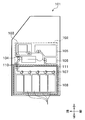
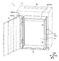
- FIG. 2 is a perspective sectional view showing the configuration of the medium storage 1.
- FIG. 3 is a side sectional view showing the configuration of the medium storage 1.
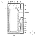
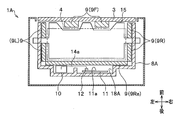
- FIG. 4 is a top sectional view showing the configuration of the medium storage 1.
- the medium storage 1 has a box-shaped housing 2.
- the cross-sectional shape of the housing 2 is a rectangular shape in which the left-right direction is a longitudinal direction and the front-rear direction is a short direction in a top view.
- the housing 2 includes a delivery port 2 a and a door 3.
- FIG. 2 shows the configuration of the medium storage 1 with the door 3 opened.
- the delivery port 2a is an opening that delivers banknotes to and from the transport path of the cash handling apparatus 101 (specifically, the sorting transport unit 107 shown in FIG. 1).
- the door 3 is a member that selectively closes or opens the interior of the housing 2.
- a stage 15 is disposed inside the housing 2.
- the shape of the stage 15 is, as viewed from above, based on a rectangular base portion with the left-right direction as the longitudinal direction and the front-back direction as the short direction, the center portion of the front side of the rectangular base portion and the right portion of the front side And a left side portion of the front side are provided with protrusions (see FIG. 4).
- the upper surface of the stage 15 is formed in a flat surface shape, and banknotes are stacked thereon.
- the stage 15 is movable in the vertical direction by a driving means (not shown), and is configured to descend as banknotes are accumulated on the upper surface of the stage 15.
- the banknote guide 9F is disposed in front of the stage 15
- the banknote guide 9Re is disposed behind the stage 15
- the banknote guide 9L is disposed on the left side of the stage 15
- the banknote guide 9R is arranged on the right side of the stage 15.
- the banknote guides 9F and 9Re are opposed to the longitudinal side of the stage 15 (that is, the longitudinal side of the banknotes accumulated on the upper surface of the stage 15).
- the banknote guides 9 ⁇ / b> L and 9 ⁇ / b> R are opposed to the lateral side of the stage 15 (that is, the lateral side of the banknotes accumulated on the upper surface of the stage 15).
- each banknote guide 9 facing the stage 15 is formed into a flat surface. This inner wall surface functions as a guide surface that abuts against the side of the bill and aligns the bill when the bill is accumulated on the upper surface of the stage 15.
- Each banknote guide 9 is arranged such that each inner wall surface (guide surface) extends in the vertical direction (vertical direction).
- the rear banknote guide 9Re is fixedly installed at a predetermined position inside the housing 2. Therefore, the banknote guide 9Re functions as a reference member for stacking banknotes at predetermined positions in the front-rear direction when stacking banknotes on the upper surface of the stage 15.
- the other banknote guides 9F, 9L, and 9R are configured to be movable in the proximity direction or the separation direction with respect to the side sides facing the stage 15.
- the medium storage 1 is configured to be able to stack banknotes in a storage space 4 surrounded by four banknote guides 9F, 9Re, 9L, 9R.
- the storage space 4 is formed to be about several millimeters larger than the size of the banknote stored inside.
- the storage space 4 is minimized when the banknote guides 9F, 9L, 9R are moved inward (when moved in the direction of proximity to the side of the stage 15).
- the storage space 4 is maximized when the banknote guides 9F, 9L, 9R are moved to the outermost side (when moved in a direction away from the side of the stage 15).
- the banknote guide 9F forms the front side surface of the storage space 4 and is fixed to the door 3 that can be opened and closed.
- the bill guide 9F (or the door 3) can be configured to include a bill stopper.
- the banknote guides 9Re, 9L, 9R form a rear side surface, a left side surface, and a right side surface of the storage space 4, and are fixed to the frame 8 of the internal structure of the medium storage case 1.
- the medium storage case 1 includes a conveyance path 5, a frame 8, a battery 10, and a control board 11 inside.
- the conveyance path 5 is a path connecting the storage space 4 and the delivery port 2a.
- the frame 8 is an internal structure of the medium storage 1.
- the battery 10 is a power supply source that supplies power to an arbitrary component such as the control board 11 or an actuator (not shown).
- the battery 10 is a primary battery, a secondary battery, or the like. For example, a cylindrical battery or a laminated battery is used.
- the control board 11 is a control unit that controls various functions of the medium storage 1.
- a feed roller 6 and a transport roller 7 are disposed around the transport path 5.
- the feeding roller 6 is a roller that feeds the banknotes accumulated in the storage space 4 to the transport path 5.
- the transport roller 7 is a roller for transporting banknotes between the storage space 4 and the delivery port 2a.
- the transport roller 7 is configured to be able to transport banknotes both in the direction from the storage space 4 to the delivery port 2a and in the direction from the delivery port 2a to the storage space 4.
- a pair of transport rollers 7 are opposed to each other up and down, and the bills are transported while being separated one by one.
- a plurality of pairs of transport rollers 7 may be arranged to face each other in the vertical direction.
- the feeding roller 6 and the conveying roller 7 are driven by an actuator (not shown).
- the frame 8 is formed in a U shape when viewed from above.
- one box-shaped recess 18 is formed on the inner wall surface of the rear portion 8Re of the frame 8 formed in a U-shape.
- the recess 18 functions as a battery space in which the battery 10 is disposed.
- the medium storage 1 has a configuration in which a battery 10 and a control board 11 are arranged between a bill guide 9Re and a housing 2 on the rear side.
- the battery 10 is housed in a recess 18 formed on the inner wall surface of the rear portion 8Re of the frame 8.
- the control board 11 is disposed between the rear portion 8Re of the frame 8 and the housing 2.
- the medium storage 1 has a configuration in which the battery 10 and the control board 11 are arranged relatively apart from each other. Therefore, the medium storage 1 is configured to supply power from the battery 10 to the control board 11 by arranging the relay connector 13 between the battery 10 and the control board 11 and relaying the power through the relay connector 13. ing.
- the relay connector 13 is disposed between the battery 10 and the control board 11.
- the battery 10 is connected to the relay connector 13 via the cable 14a.
- the cable 14 a and the relay connector 13 are housed in the recess 18 together with the battery 10.
- control board 11 is connected to the relay connector 13 via the cable 14b.
- the control board 11 is arranged so that the connector mounting surface 11a faces the storage space 4.
- a board connector 12 for connecting to the battery 10 is provided on the connector mounting surface 11a.
- a cable 14 b is connected to the board connector 12.
- the recess 18 contains only one battery 10.
- the recess 18 can be formed to accommodate a plurality of batteries 10.
- the batteries 10 are connected in parallel.
- the medium storage 1 can supply power to the control board 11 for a relatively long period of time.
- Each battery 10 may be connected in series.
- control board 11 has the communication function which communicates with the control part of the cash handling apparatus 101 wirelessly or by wire, the monitoring function which monitors the amount of banknotes inside the medium storage 1, and the remaining amount of the battery 10, for example.
- a detection function, a conveyance control function for controlling conveyance of banknotes by driving an actuator (not shown), and the like are provided.
- the control board 11 communicates with the control unit of the cash handling apparatus 101 and notifies the control unit of the cash handling apparatus 101 of the amount of bills inside the medium storage 1. .
- the control board 11 communicates with the control unit of the cash handling apparatus 101 when the remaining amount of the battery 10 becomes low or when the remaining amount of the battery 10 becomes zero, for example. Request.
- the control board 11 can also be configured to have the following anti-theft function, for example.
- anti-theft function for example, in the case of a criminal act (emergency) in which the cash handling apparatus 101 is destroyed and the banknotes stored therein are stolen, the cash handling apparatus 101 is spoiled by jetting liquid (ink) onto the banknotes.
- jetting liquid in the case of a criminal act (emergency) in which the cash handling apparatus 101 is destroyed and the banknotes stored therein are stolen, the cash handling apparatus 101 is spoiled by jetting liquid (ink) onto the banknotes.
- jetting liquid a state in which liquid penetrates into the inside of a bill.
- This function is realized, for example, by providing a liquid ejecting mechanism in the medium storage case 1.
- the liquid ejecting mechanism makes it difficult to use banknotes by fouling the banknotes stored in the medium storage case 1 if the criminal act (emergency) described above occurs. Put it in a state.
- the liquid ejecting mechanism prevents the stolen banknote from being used.
- the liquid ejecting mechanism makes it easy to discover that a stolen banknote has been used if a stolen banknote is used, and a person who uses the stolen banknote Therefore, it is possible to prevent the above-mentioned criminal act (emergency) from occurring again.
- the rear banknote guide 9Re is formed to be attachable to and detachable from the frame 8.
- the battery 10 is disposed between the rear portion 8Re of the frame 8 and the rear bill guide 9Re.
- the surface of the rear bill guide 9Re is formed as a guide surface that forms the storage space 4. Further, the back surface of the rear bill guide 9 is formed as a cover surface that covers all or a part of one side surface of the battery 10.
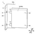
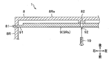
- FIGS. 5A and 5B are diagrams showing the configuration of the rear banknote guide 9Re.
- FIG. 5A shows the configuration of the banknote guide 9Re detached from the frame 8
- FIG. 5B shows the configuration of the banknote guide 9Re when attached to the frame 8.
- a description will be given assuming that the operator attaches the bill guide 9Re detached from the frame 8 to the frame 8.
- the rear banknote guide 9Re includes a protrusion 91 that is inserted into a groove 81 formed in the frame 8 and an insertion hole 92 through which the male screw 19 is inserted.
- two protrusions 91 are formed on the right side surface of the banknote guide 9Re, and two insertion holes 92 are formed to penetrate from the inner wall surface of the banknote guide 9Re to the outer wall surface. Yes.
- the frame 8 includes a groove portion 81 into which the projection 91 of the bill guide 9Re is inserted, and a female screw portion 82 (see FIG. 5B) to which the male screw 19 is attached.
- the two groove portions 81 penetrate from the inner wall surface of the right portion 8R of the frame 8 formed in a U shape to the outer wall surface so as to correspond to the two protrusion portions 91 of the banknote guide 9Re. Is formed.
- the two female screw portions 82 are formed to protrude from the inner wall surface of the rear portion 8Re of the U-shaped frame 8 so as to correspond to the two insertion holes 92 of the bill guide 9Re. Has been.
- the operator when attaching the bill guide 9Re to the frame 8, the operator first inserts the two protrusions 91 of the bill guide 9Re into the two grooves 81 of the frame 8 as shown in FIG. 5A.
- the protrusion 91 of the bill guide 9Re and the groove 81 of the frame 8 function as a positioning portion that defines the position of the bill guide 9Re.
- the bill guide 9Re is arranged at a predetermined position.
- the insertion hole 92 of the banknote guide 9Re and the female screw portion 82 of the frame 8 are in agreement.
- the operator passes the male screw 19 through the insertion hole 92 of the bill guide 9Re and attaches it to the female screw portion 82 of the frame 8.
- the insertion hole 92 of the bill guide 9Re, the female screw portion 82 of the frame 8, and the male screw 19 function as a fixing portion that fixes the bill guide 9Re to the frame 8. Accordingly, at this time, the bill guide 9Re is fixed to the frame 8.
- the banknote guide 9Re When the banknote guide 9Re is fixed to the frame 8, the banknote guide 9Re covers all or part of one side surface of the battery 10. That is, the bill guide 9Re functions as a cover that covers all or part of one side surface of the battery 10 by being attached to the frame 8.
- the bill guide 9Re covers one side surface of the relay connector 13 that connects the control board 11 and the battery 10. That is, the bill guide 9Re functions as a cover that covers one side surface of the relay connector 13 by being attached to the frame 8.
- the medium storage 1 takes in the banknote through the delivery port 2a and stores it in the storage space 4.
- the medium storage case 1 stacks the banknotes on the stage 15 while suppressing the variation in the position of each banknote to several millimeters by the four banknote guides 9F, 9Re, 9L, and 9R.
- the medium storage 1 controls the vertical position of the stage 15 so as to keep the position (upper surface) of the uppermost banknote constant according to the number of stored banknotes.
- the control board 11 of the medium storage 1 communicates with the control unit of the cash handling apparatus 101 when the remaining amount of the battery 10 becomes low during operation or when the remaining amount of the battery 10 becomes zero.
- the battery 10 is requested to be replaced.
- the control unit of the cash handling apparatus 101 instructs the worker to replace the battery 10 by any notification means.
- the worker When the worker is instructed to replace the battery 10, the worker opens the door 3 of the medium storage 1 and removes the banknotes stored in the medium storage 1 from the stage 15. Then, the worker removes the rear bill guide 9Re from the frame 8. Then, one side surface of the battery 10 is exposed. As a result, the battery 10 can be removed.
- the worker removes the battery 10 from the cable 14a (see FIG. 4), and instead attaches a new battery 10 to the cable 14a. In this way, the worker replaces the old battery 10 with a new battery 10.
- the worker When the worker replaces the battery 10, the worker attaches the rear bill guide 9Re to the frame 8. The worker closes the door 3 of the medium storage case 1 after returning the banknotes stored in the medium storage case 1 onto the stage 15. Thereby, the replacement work of the battery 10 is completed.
- the medium storage case 1 is configured to cover all or a part of one side surface of the battery 10 with the back banknote guide 9Re. That is, the rear bill guide 9Re has both a function as a guide surface that forms the storage space 4 and a function as a cover surface that covers all or part of one side surface of the battery 10.
- Such a medium storage case 1 can stack banknotes on the stage 15 while suppressing the variation in the position of each banknote to several millimeters when the rear banknote guide 9Re is attached to the frame 8. . Further, the medium storage 1 can expose the battery 10 only by removing the rear bill guide 9Re from the frame 8, and as a result, the battery 10 can be replaced.
- Such a medium storage 1 can function the rear banknote guide 9Re as a cover for the battery 10, and therefore, unlike a conventional medium storage, a battery-dedicated cover can be deleted. Therefore, the medium storage 1 can reduce the number of parts, and as a result, the unit price can be reduced.
- the worker When accessing the control board 11, the worker removes the bill guide 9Re from the frame 8 and then releases the connection between the relay connector 13 and the cable 14b. The operator can access the control board 11 by pulling out the control board 11 from behind the rear portion 8Re of the frame 8.
- the medium storage 1 may have a configuration in which the rear banknote guide 9Re is divided into two banknote guides 9a and 9b, for example.
- the number of parts can be reduced.
- the medium storage 1 according to the first embodiment has a configuration in which a battery 10 and a control board 11 are arranged relatively apart from each other.
- the second embodiment provides a medium storage 1A having a configuration in which the battery 10 and the control board 11 are arranged closer to each other than the medium storage 1 according to the first embodiment.
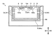
- FIG. 6 is a top sectional view showing the configuration of the medium storage case 1A.
- the concave portion 18A wider than the concave portion 18 of the first embodiment is behind the frame 8A. It is different in that it is formed on the inner wall surface of the part 8Re and that the battery 10 and the control board 11 are arranged inside the recess 18A.
- the battery 10 and the control board 11 are arranged inside a recess 18A formed on the inner wall surface of the rear portion 8Re of the frame 8A.
- a medium storage 1A has a configuration in which the battery 10 and the control board 11 are arranged closer to each other than the medium storage 1 according to the first embodiment. Therefore, unlike the medium storage 1 according to the first embodiment, the medium storage 1A can be configured to directly supply power from the battery 10 to the control board 11 without being relayed by the relay connector 13. Specifically, the medium storage 1A can be configured such that the battery 10 and the board connector 12 are directly connected by a cable 14a.
- the medium storage 1 ⁇ / b> A can delete the battery-dedicated cover used for the conventional medium storage as in the medium storage 1 according to the first embodiment. Therefore, the medium storage 1 ⁇ / b> A can reduce the number of parts in the same manner as the medium storage 1 according to the first embodiment.
- the medium storage 1A has a configuration in which the battery 10 and the board connector 12 are directly connected by a cable 14a. Therefore, the medium storage 1A can delete the relay connector 13 and the cable 14b used in the medium storage 1 according to the first embodiment. Therefore, the medium storage 1A can further reduce the number of parts compared to the medium storage 1 according to the first embodiment.
- the medium storage case 1A the battery 10 and the control board 11 are arranged inside a recess 18A formed on the inner wall surface of the rear portion 8Re of the frame 8A. Therefore, the medium storage case 1A can expose the battery 10 and the control board 11 only by removing the rear bill guide 9Re from the frame 8A. Therefore, the medium storage 1 ⁇ / b> A can replace the battery 10 by performing the same operation as the medium storage 1 according to the first embodiment.
- the conventional medium storage in order to access the connector of the control board, it was necessary to remove the cover provided on the housing. Therefore, the conventional medium storage cannot easily perform operations such as firmware update.
- the medium storage case 1A can allow the operator to visually recognize the connector mounting surface 11a of the control board 11 only by removing the rear bill guide 9Re from the frame 8A. Therefore, the medium storage 1A can access the control board 11 more easily than the medium storage 1 according to the first embodiment. Thereby, the medium storage 1A can easily perform operations such as firmware update. Therefore, the medium storage 1A can improve workability such as firmware update.
- the medium storage case 1 ⁇ / b> A is configured to have one rear bill guide 9 ⁇ / b> Re.
- the banknote guide 9Re of the medium storage case 1A has the same configuration as the banknote guide 9Re of the medium storage case 1 shown in FIG. 5A.
- the medium storage case 1 ⁇ / b> A is transformed into a configuration having a plurality of rear banknote guides (in the example shown in FIG. 7, two rear banknote guides 9 a and 9 b). Can do.
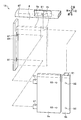
- FIG. 7 is a diagram showing the configuration of the rear banknote guides 9a and 9b according to the modification.
- the bill guide 9 a is configured to cover all or part of one side surface of the control board 11, and the bill guide 9 b is configured to cover all or part of one side surface of the battery 10.
- the bill guide 9a is referred to as “substrate side guide 9a”
- the bill guide 9b is referred to as “battery side guide 9b”.
- the substrate side guide 9a is different from the banknote guide 9Re shown in FIG. 5A in that the width in the left-right direction is short.
- the battery-side guide 9b has a short width in the left-right direction and a protrusion 91, which is removed from the right side, and is formed on the upper side instead of the banknote guide 9Re shown in FIG. 5A. It is different in point.
- the width in the left-right direction of the board-side guide 9a is longer than the width in the left-right direction of the battery-side guide 9b.
- the lateral width of the battery side guide 9b may be longer than the lateral width of the board side guide 9a.
- the medium storage 1A has a frame 8T.
- the frame 8T is a member disposed above the board side guide 9a and the battery side guide 9b.
- the frame 8T includes a groove 81 into which the protrusion 91 of the battery side guide 9b is inserted.
- the medium storage case 1A includes four female screw portions so as to correspond to the two insertion holes 92 of the board side guide 9a and the two insertion holes 92 of the battery side guide 9b.
- 82 protrudes from the inner wall surface of the rear portion 8Re of the frame 8 formed in a U-shape.
- the operator opens the door 3 of the medium storage 1A, and the banknotes stored in the medium storage 1A from above the stage 15. Remove. Then, the worker removes the battery side guide 9b from the frame 8. Then, one side surface of the battery 10 is exposed. As a result, the battery 10 can be removed. The worker replaces the old battery 10 with a new battery 10 and attaches the battery side guide 9 b to the frame 8. Then, the worker returns the banknotes stored in the medium storage 1 ⁇ / b> A onto the stage 15, and then closes the door 3 of the medium storage 1 ⁇ / b> A. Thereby, the replacement work of the battery 10 is completed.
- the worker may access the control board 11 by removing the board side guide 9a from the frame 8, or may replace the control board 11 in some cases. Can do.
- the modified example is configured such that an operator can efficiently access the battery 10 by dividing the banknote guide on the rear side into the substrate side guide 9a and the battery side guide 9b.
- the reason is that the worker access frequency to the battery 10 is overwhelmingly higher than the worker access frequency to the control board 11.
- the battery 10 can be replaced simply by removing the battery side guide 9b from the frame 8. Therefore, the modification can improve the ease of replacement of the battery 10.
- the number of parts can be reduced as in the medium storage 1 according to the first embodiment. Moreover, according to the medium storage 1 ⁇ / b> A, the number of parts can be further reduced as compared with the medium storage 1 according to the first embodiment.
- the medium storage 1 has a configuration in which a battery 10 and a control board 11 are arranged between a bill guide 9Re and a housing 2 on the back.
- the inner wall surface portion of the door 3 is regarded as one part of the frame, and the battery 10 and the control board 11 are arranged between the banknote guide 9F and the door 3 in front.
- a medium storage 1B is provided.
- FIG. 8 is a top cross-sectional view showing the configuration of the medium storage 1B.
- the battery 10 and the control board 11 are connected to the front bill guide 9 ⁇ / b> F and the door 3 as compared with the medium storage 1 according to the first embodiment.
- the difference is that the frame 8B is provided in place of the frame 8 instead of the frame 8.
- a space 18Ba for storing the battery 10 and a space 18Bb for storing the control board 11 are formed on the inner wall surface of the door 3.
- the battery 10 and the control board 11 are directly connected by a cable 14a.
- the space 18Ba for storing the battery 10 and the space 18Bb for storing the control board 11 may be integrated into one.
- the medium storage 1 ⁇ / b> B has a frame 8 ⁇ / b> B instead of the frame 8.
- the frame 8B is different from the frame 8 of the first embodiment in that the concave portion 18 is removed.
- the medium storage 1 ⁇ / b> B can delete the battery-dedicated cover used in the conventional medium storage as in the medium storage 1 according to the first embodiment. Therefore, the medium storage 1 ⁇ / b> B can reduce the number of parts in the same manner as the medium storage 1 according to the first embodiment.
- the medium storage 1B has a configuration in which the battery 10 and the board connector 12 are directly connected by a cable 14a. Therefore, the medium storage 1B can delete the relay connector 13 and the cable 14b used in the medium storage 1 according to the first embodiment. Therefore, the medium storage 1 ⁇ / b> B can further reduce the number of parts compared to the medium storage 1 according to the first embodiment.
- the medium storage 1B has the battery 10 and the control board 11 arranged on the inner wall surface of the door 3, for example, a new function can be easily added only by replacing the door 3.
- the medium storage 1 ⁇ / b> B can be easily changed from a configuration without the anti-theft function to a configuration with the anti-theft function by simply replacing the door 3.
- the number of parts can be reduced as in the medium storage case 1 according to the first embodiment. Moreover, according to the medium storage 1B, the number of parts can be further reduced as compared with the medium storage 1 according to the first embodiment.
- the medium storage 1C is configured such that the battery 10 and the control board 11 are disposed between the left banknote guide 9L (or the right banknote guide 9R) and the housing 2. provide.
- FIG. 9 is a top view cross-sectional view showing the configuration of the medium storage 1C.
- the medium storage case 1C according to the fourth embodiment has a frame 8C instead of the frame 8 as compared with the medium storage case 1 according to the first embodiment, and a battery. 10 and the control board 11 are different in that they are arranged between the banknote guide 9L on the left side and the housing 2.
- the frame 8C is different from the frame 8 of the first embodiment in that the concave portion 18 is removed from the rear portion 8Re, and the left portion 8L is shifted to the left instead.
- the space 18C is formed between the left part 8L of the frame 8C and the bill guide 9L.
- the battery 10 and the control board 11 are arrange
- the medium storage 1 ⁇ / b> C has a configuration in which the battery 10 and the control board 11 are disposed between the banknote guide 9 ⁇ / b> L on the left side and the housing 2.
- the medium storage 1C has a configuration in which the battery 10 and the control board 11 are arranged between the right banknote guide 9R and the housing 2 (that is, a configuration in which the left and right are reversed with respect to the example shown in FIG. 9). It may be.
- the medium storage 1C can delete the battery-dedicated cover used in the conventional medium storage, similarly to the medium storage 1 according to the first embodiment. Therefore, the medium storage 1C can reduce the number of parts, similarly to the medium storage 1 according to the first embodiment.
- the medium storage 1C has a configuration in which the battery 10 and the board connector 12 are directly connected by a cable 14a. Therefore, the medium storage 1C can delete the relay connector 13 and the cable 14b used in the medium storage 1 according to the first embodiment. Therefore, the medium storage 1C can further reduce the number of parts compared to the medium storage 1 according to the first embodiment.
- the number of parts can be reduced as in the medium storage 1 according to the first embodiment.
- the present invention is not necessarily limited to the one having all the configurations described. Further, according to the present invention, a part of the configuration of one embodiment can be added to or replaced with the configuration of another embodiment. In the present invention, a part of the configuration can be deleted from the configuration of an embodiment.
- the medium storage 1 can be used not only for a cash dispenser (CD) and an automatic teller machine (ATM), but also for a ticket issuing machine and other cash handling devices.
- CD cash dispenser
- ATM automatic teller machine
- the battery 10 and the control board 11 are concentrated on the inner side of one of the four banknote guides 9F, 9Re, 9L, and 9R. .
- the battery 10 and the control board 11 can be distributed and arranged inside any one of the plurality of bill guides 9 among the four bill guides 9F, 9Re, 9L, 9R.
- a plurality of batteries 10 and control boards 11 can be provided, respectively, and any combination can be provided inside one or more of the four banknote guides 9F, 9Re, 9L, 9R. Can be arranged.
- the medium storage 1 may be configured to charge the battery 10 when the battery 10 is configured as a secondary battery.
- a configuration can be realized, for example, by using a known non-contact power supply unit that includes a power transmission device and a power reception device.
- a configuration can be realized by arranging the power transmission device of the non-contact power supply means in the cash handling device and arranging the power reception device of the non-contact power supply means in the medium storage 1. it can.
- the power transmission device transmits a high-frequency signal to the power reception device, while the power reception device converts the received high-frequency signal into electric power.
- the cash handling apparatus having this configuration supplies power to the medium storage 1 in a non-contact state.
- the power supply amount of the non-contact power supply means is smaller than the maximum power consumption amount of the actuator (medium transport means).
- the maximum power consumption consumed in the medium storage 1 is the maximum power consumption of an actuator (medium transport unit) for transporting the medium.
- the cash handling apparatus having this configuration can be used while the actuator (medium transport unit) is not driven even if the power supply amount of the non-contact power supply unit is smaller than the maximum power consumption amount of the actuator (medium transport unit).
- the cash handling apparatus can supply the medium storage 1 with a sufficient amount of power even when using a non-contact power supply means that can supply less power than the maximum power consumption of the actuator.
- the battery 10 is configured as a secondary battery, so that the replacement period can be prolonged as compared with the case where the primary battery is used.
Landscapes
- Physics & Mathematics (AREA)
- General Physics & Mathematics (AREA)
- Pile Receivers (AREA)
- Battery Mounting, Suspending (AREA)
- Purses, Travelling Bags, Baskets, Or Suitcases (AREA)
Priority Applications (3)
| Application Number | Priority Date | Filing Date | Title |
|---|---|---|---|
| BR112017024218A BR112017024218A2 (pt) | 2015-06-11 | 2016-05-10 | caixa de armazenamento de mídia e dispositivo de manejo de dinheiro em espécie. |
| RU2017134823A RU2679281C1 (ru) | 2015-06-11 | 2016-05-10 | Контейнер для хранения средств обращения и устройство обработки денег |
| US15/575,192 US20180151019A1 (en) | 2015-06-11 | 2016-05-10 | Medium storage box and cash handling device |
Applications Claiming Priority (2)
| Application Number | Priority Date | Filing Date | Title |
|---|---|---|---|
| JP2015118622A JP6531506B2 (ja) | 2015-06-11 | 2015-06-11 | 媒体収納庫、及び、現金取扱装置 |
| JP2015-118622 | 2015-06-11 |
Publications (1)
| Publication Number | Publication Date |
|---|---|
| WO2016199533A1 true WO2016199533A1 (ja) | 2016-12-15 |
Family
ID=57504825
Family Applications (1)
| Application Number | Title | Priority Date | Filing Date |
|---|---|---|---|
| PCT/JP2016/063924 WO2016199533A1 (ja) | 2015-06-11 | 2016-05-10 | 媒体収納庫、及び、現金取扱装置 |
Country Status (6)
Families Citing this family (3)
| Publication number | Priority date | Publication date | Assignee | Title |
|---|---|---|---|---|
| RU194675U1 (ru) * | 2019-08-12 | 2019-12-18 | Андрей Владимирович Лушников | Автомат для выдачи денег |
| US11990008B2 (en) * | 2020-12-16 | 2024-05-21 | Ncr Corporation | Dissuasion cassette, system, and apparatus against currency theft from media depository |
| RU207607U1 (ru) * | 2021-04-05 | 2021-11-03 | Алексей Николаевич Зякун | Тестер ресайклинговых кассет устройств самообслуживания |
Citations (5)
| Publication number | Priority date | Publication date | Assignee | Title |
|---|---|---|---|---|
| JPH0948534A (ja) * | 1995-08-08 | 1997-02-18 | Sanyo Electric Co Ltd | 紙幣搬送装置 |
| JPH11232524A (ja) * | 1998-02-02 | 1999-08-27 | Hitachi Ltd | 紙幣収納カセット |
| JPH11250312A (ja) * | 1998-02-27 | 1999-09-17 | Toshiba Corp | 小束処理装置および小束処理装置の小束収納庫 |
| JP2001175918A (ja) * | 1999-12-14 | 2001-06-29 | Oki Joho Systems:Kk | 媒体収納装置 |
| JP2007052523A (ja) * | 2005-08-16 | 2007-03-01 | Oki Electric Ind Co Ltd | 媒体収納装置 |
Family Cites Families (10)
| Publication number | Priority date | Publication date | Assignee | Title |
|---|---|---|---|---|
| JP3242598B2 (ja) * | 1997-06-27 | 2001-12-25 | 三菱電機株式会社 | 演算機能付き情報転送装置 |
| JPH11250310A (ja) * | 1998-02-27 | 1999-09-17 | Toshiba Corp | 小束処理装置および小束処理装置の小束収納庫 |
| PL376078A1 (en) * | 2002-12-31 | 2005-12-12 | Diebold, Incorporated | Atm currency cassette arrangement |
| CA2733476C (en) * | 2003-03-10 | 2015-12-15 | Diebold, Incorporated | Cash dispensing automated banking machine with deposit holding container |
| US20080007146A1 (en) * | 2006-05-18 | 2008-01-10 | De La Rue International Limited | Cash dispenser |
| US7857114B2 (en) * | 2008-07-07 | 2010-12-28 | Glory, Ltd. | Banknote discrimination apparatus and banknote discrimination method |
| MX2012003467A (es) * | 2009-09-22 | 2012-07-20 | Mei Inc | Conjunto de almacenamiento de documentos. |
| US10837218B2 (en) * | 2012-08-02 | 2020-11-17 | Magneto Ip Holdings (Pty) Ltd | Bank note protection |
| EP2879102A1 (de) * | 2013-12-02 | 2015-06-03 | Wincor Nixdorf International GmbH | Geldkassette und Geldautomat |
| US9613502B2 (en) * | 2014-05-23 | 2017-04-04 | Diebold, Incorporated | Wireless interface for ATM cassette and money transport |
-
2015
- 2015-06-11 JP JP2015118622A patent/JP6531506B2/ja active Active
-
2016
- 2016-05-10 BR BR112017024218A patent/BR112017024218A2/pt not_active Application Discontinuation
- 2016-05-10 MY MYPI2017704344A patent/MY180673A/en unknown
- 2016-05-10 US US15/575,192 patent/US20180151019A1/en not_active Abandoned
- 2016-05-10 RU RU2017134823A patent/RU2679281C1/ru active
- 2016-05-10 WO PCT/JP2016/063924 patent/WO2016199533A1/ja active Application Filing
Patent Citations (5)
| Publication number | Priority date | Publication date | Assignee | Title |
|---|---|---|---|---|
| JPH0948534A (ja) * | 1995-08-08 | 1997-02-18 | Sanyo Electric Co Ltd | 紙幣搬送装置 |
| JPH11232524A (ja) * | 1998-02-02 | 1999-08-27 | Hitachi Ltd | 紙幣収納カセット |
| JPH11250312A (ja) * | 1998-02-27 | 1999-09-17 | Toshiba Corp | 小束処理装置および小束処理装置の小束収納庫 |
| JP2001175918A (ja) * | 1999-12-14 | 2001-06-29 | Oki Joho Systems:Kk | 媒体収納装置 |
| JP2007052523A (ja) * | 2005-08-16 | 2007-03-01 | Oki Electric Ind Co Ltd | 媒体収納装置 |
Also Published As
| Publication number | Publication date |
|---|---|
| RU2679281C1 (ru) | 2019-02-06 |
| US20180151019A1 (en) | 2018-05-31 |
| JP6531506B2 (ja) | 2019-06-19 |
| JP2017004317A (ja) | 2017-01-05 |
| BR112017024218A2 (pt) | 2018-07-17 |
| MY180673A (en) | 2020-12-05 |
Similar Documents
| Publication | Publication Date | Title |
|---|---|---|
| KR101224937B1 (ko) | 지폐 수납고 및 지폐 취급 장치 | |
| JP5108087B2 (ja) | 紙葉類処理装置 | |
| JP2011233084A (ja) | 紙葉類処理装置 | |
| WO2016199533A1 (ja) | 媒体収納庫、及び、現金取扱装置 | |
| US11745967B2 (en) | Paper feed tray, paper feed device, and circulation-type paper sheet processing device | |
| JP3451988B2 (ja) | 紙幣カセット | |
| WO2010032281A1 (ja) | 紙幣入金処理ユニット、および紙幣入金処理ユニットに脱着可能な投入・返却ユニット | |
| WO2014034246A1 (ja) | 紙葉類取扱装置及び紙葉類収納庫 | |
| KR101456367B1 (ko) | 매체 처리 장치 | |
| JP5481633B2 (ja) | 還流式紙幣処理装置 | |
| WO2011036806A1 (ja) | 収納庫および紙葉類処理装置 | |
| JP2021105891A (ja) | 紙葉類処理装置 | |
| JP5511109B2 (ja) | 紙葉類処理装置 | |
| JP2018152029A (ja) | 紙葉類処理システム、紙葉類処理装置及び紙葉類収容部 | |
| JP2007052523A (ja) | 媒体収納装置 | |
| KR20170077148A (ko) | 지폐 처리 장치 | |
| KR102312025B1 (ko) | 지폐 처리 장치 | |
| WO2018012228A1 (ja) | 収納袋および紙葉類処理装置 | |
| JP2003162750A (ja) | 紙幣カセット及び紙幣取扱装置 | |
| JP2019066962A (ja) | 媒体収納庫及び自動取引装置 | |
| JP2016062427A (ja) | 紙幣取扱装置 | |
| JPH11154259A (ja) | 紙幣入出金機のスタッカ着脱構造 | |
| JP2021144440A (ja) | 紙葉類収納装置及び紙葉類処理装置 | |
| JP2022139306A (ja) | 貨幣処理装置、及び、アタッチメント | |
| JP4962357B2 (ja) | 紙幣処理装置 |
Legal Events
| Date | Code | Title | Description |
|---|---|---|---|
| 121 | Ep: the epo has been informed by wipo that ep was designated in this application |
Ref document number: 16807240 Country of ref document: EP Kind code of ref document: A1 |
|
| WWE | Wipo information: entry into national phase |
Ref document number: 2017134823 Country of ref document: RU |
|
| WWE | Wipo information: entry into national phase |
Ref document number: 15575192 Country of ref document: US |
|
| NENP | Non-entry into the national phase |
Ref country code: DE |
|
| REG | Reference to national code |
Ref country code: BR Ref legal event code: B01A Ref document number: 112017024218 Country of ref document: BR |
|
| 122 | Ep: pct application non-entry in european phase |
Ref document number: 16807240 Country of ref document: EP Kind code of ref document: A1 |
|
| ENP | Entry into the national phase |
Ref document number: 112017024218 Country of ref document: BR Kind code of ref document: A2 Effective date: 20171110 |