WO2016199308A1 - Suit pattern and measuring device for suit pattern - Google Patents
Suit pattern and measuring device for suit pattern Download PDFInfo
- Publication number
- WO2016199308A1 WO2016199308A1 PCT/JP2015/067092 JP2015067092W WO2016199308A1 WO 2016199308 A1 WO2016199308 A1 WO 2016199308A1 JP 2015067092 W JP2015067092 W JP 2015067092W WO 2016199308 A1 WO2016199308 A1 WO 2016199308A1
- Authority
- WO
- WIPO (PCT)
- Prior art keywords
- shoulder
- length
- line
- point
- base point
- Prior art date
Links
Images


Classifications
-
- A—HUMAN NECESSITIES
- A41—WEARING APPAREL
- A41H—APPLIANCES OR METHODS FOR MAKING CLOTHES, e.g. FOR DRESS-MAKING OR FOR TAILORING, NOT OTHERWISE PROVIDED FOR
- A41H3/00—Patterns for cutting-out; Methods of drafting or marking-out such patterns, e.g. on the cloth
-
- A—HUMAN NECESSITIES
- A41—WEARING APPAREL
- A41D—OUTERWEAR; PROTECTIVE GARMENTS; ACCESSORIES
- A41D1/00—Garments
- A41D1/02—Jackets
-
- A—HUMAN NECESSITIES
- A41—WEARING APPAREL
- A41H—APPLIANCES OR METHODS FOR MAKING CLOTHES, e.g. FOR DRESS-MAKING OR FOR TAILORING, NOT OTHERWISE PROVIDED FOR
- A41H1/00—Measuring aids or methods
- A41H1/02—Devices for taking measurements on the human body
-
- A—HUMAN NECESSITIES
- A41—WEARING APPAREL
- A41H—APPLIANCES OR METHODS FOR MAKING CLOTHES, e.g. FOR DRESS-MAKING OR FOR TAILORING, NOT OTHERWISE PROVIDED FOR
- A41H3/00—Patterns for cutting-out; Methods of drafting or marking-out such patterns, e.g. on the cloth
- A41H3/06—Patterns on paper
Definitions
- the present invention relates to a spine prototype and a measuring instrument for the spine prototype.
- each pattern is based on an upper pattern formed by integrally cutting the buttocks and left and right sleeves and a lower pattern formed by integrally cutting the front and back bodies.
- the garment is lightened, and the wearer's movement is not limited, making it easy to move and workability. It is possible to provide comfortable clothes with excellent safety.
- the arm member connected to the upper part of the front body and the back body is divided into a forearm member, a rear arm member, and a lower arm member, and the sleeve is made of at least three members, and the shape of each arm member Is curved in a certain direction, or the side edge part attached to the front body and the back body intersects at an acute angle, and the intersection of the acute angle becomes a buttock to form a necessary space for exercise in the sewing state .
- the sleeve part is lightly bent at the elbow to form a three-dimensional shape close to the curve of the arm protruding diagonally downward and forward, and the outerwear has good wearing feeling with respect to the movement of the arm front and rear, left and right It is said.
- a suit is created by stitching the left and right body parts, which are formed by dividing the main body of the back into the left and right sides from the back center line, and stitching them together at the back.
- Each body part is composed of a combination of a front body and a back body. At that time, measure the length between both shoulder widths, length, bust length, waist length, sleeve length, etc. so that it matches the body shape of the standard wearer as much as possible.
- left and right half body parts or left and right half body parts for standard backs for each body type, or specific wearers based on orders from specific people
- the left and right half body parts tailored to the body shape of the body are made, and the suit is made based on these left and right half body parts.
- the part of the upper body to be measured in the production of such a suit is limited to the part traditionally specified from ancient times such as the height, bust line, shoulder width, sleeve length, and the like.
- the conventional tailoring does not consider the measurement of the body part that is most necessary to fit the body shape, such as the inclination of the shoulder of the wearer, the shoulder length, the forward inclination of the back, and the body.
- the point that becomes the base point of the measurement part of the wearer's body shape is a point temporarily determined from the measurement values such as the chest circumference, and the ground height before and after the body is added as a correction coefficient to this point, and various points of the wearer are added to the point.
- the base point of the correct measurement site is determined by taking into account additional factors of displacement, such as different body, forward bending (back of the back), shoulder angle, length, etc., and the body shape based on the correct base point
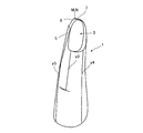
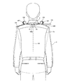
- This invention consists of a left half part and a right half part formed by dividing the outer jacket main body into left and right parts from the back center line of the back part, and a substantially elliptical shape formed by partially cutting the upper part of the center upper part of the left and right half parts.
- the left and right sleeve holes, the heel formed at the front edge of the left body part body, the chest width part in front of the sleeve hole part, the side width part below the sleeve hole part, and the back behind the sleeve hole part The upper part of the original centerline of the wearer's original back center line, formed by joining and sewing together the partially cut ends of the left and right cuffs and the back sewing lines of the left and right body parts.
- the back base point to be moved From the back base point to be moved, it moves forward by a length calculated by applying a pre-defined correction formula to the length of the chest circumference or the length around the neck, and from the moved point to about 1/4 of the movement length
- the point identified by moving vertically up the length of The point specified by the intersection of the vertical line approximately 0.5 to 0.6 times the length from the front edge to the front edge of the cuff and the absolute horizontal line from the virtual base point behind the left and right shoulders The length of the curved neck line from the back base point of the back of the back to the virtual base point before and after the left and right shoulders and the standard temporary reference point specified in the middle of the neck line.
- the length from the reference point specified in the middle of the neck line using the difference value to the ground level passing through the back of the wearer's body and the length from the chest side to the ground level
- the correct left and right shoulder front and rear base positions are determined by correcting each and the correct right and left shoulder front base points, or a line connected to the notch front
- the present invention provides a broad-type prototype characterized by the above.
- the correction formula applied to the chest circumference from the back center line when specifying the left and right shoulder back base points is (0.15 to 0.20) about 1/2 of the chest circumference. It is intended to provide a prototype of the spine characterized by multiplication.
- the correction formula applied to the length around the neck from the back center line when specifying the length around the neck is (10-15) added to the length around the neck, and the total is calculated as
- the present invention provides a broad-type prototype characterized by dividing by (5-7).
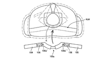
- a curved frame 100a that can be mounted and placed around the rear neck of the wearer; Left and right inclined plates 104 and 105 pivotally supported on the left and right ends of the curved frame 100a via the pivot shaft 106, and left and right shoulder front and rear base points (N, M) set on the free end of the curved frame 100a to the ground surface GL
- the curved frame 100a has a left half-curved portion 101a and a right half-curved portion 102a as separate bodies, and one of the curved portions 101a or 102a has a base end on the other side.
- the bent portion 101a or 102a is a telescopic mechanism in which the base end can be freely inserted, and the ground height measuring device includes an upper half measuring measure 121 that is suspended from the left and right shoulder front and rear base points (N, M) to the back side or the chest side downward. , And a measurement weight for a prototype with a reflection function, which is provided at the lower end of the upper half measurement measure 121 and irradiates the ground surface GL with infrared rays and receives the reflection from the ground surface GL. It is a vessel.
- the basic idea of the present invention is to measure the length of the chest circumference or neck that is an objective numerical value of the wearer, apply the correction formula to it,
- the virtual base points around the left and right shoulders are set at a certain distance and place from the back base point.
- the basic idea is to set each point of the pattern required for the spine prototype using the right and left shoulder front and back base points as the origin of all dimensions.
- the calculated value of the curved neck line calculated from the chest circumference of the actual wearer, etc., and the body front and back surfaces from the standard temporary reference point in the middle of the neck line It is characterized by the use of various elements such as the length of the distance to the ground surface, and by this method, no matter how the wearer's physical shape is different, the left and right of the shoulder of the human body and the human body are always centered on the back base point.
- the front and back shoulders have balanced “Yajirobe” postures, so that they can provide the best model with the best comfort.
- the virtual base points before and after the left and right shoulders are specified on both shoulder portions by a certain method, and the wearer's specific body shape is taken into consideration for this base point.
- the correct base point is identified, and various dimensions necessary for the back, such as the shoulder inclination and the length to the collar, are calculated based on the correct base point.
- the position of the subsequent virtual base point is specified by applying a certain correction formula to the length of the chest circumference or neck circumference of the wearer, and then the back base point and the left shoulder that should be the upper end of the wearer's original back center line
- the length of the curved scruff line between the virtual base point and the back is correct by increasing or decreasing the length of the middle part of the scruff line that passes through the chest and back from the standard temporary point to the ground.
- Identify the left shoulder back base point and correct from this correct left shoulder back base point By identifying the front shoulder base, it is possible to produce clothes that fit the body shape unique to the wearer, such as the shoulder, the cradle type, the back of the back, and the body, and it is also easy to create a pattern that represents such a measurement and the prototype of the suit, There is an effect that it is possible to produce a spine prototype that accurately fits each person's body shape without the need for highly skilled skills.
- the garment made with such a stencil prototype fits the wearer's body precisely and has a shoulder that is easy to act on, so the left and right arms do not cause unnecessary wrinkles near the back of the neck or around the shoulder when worn.
- the right and left shoulder front and back base points are temporarily identified based on the length from the back base point along the neck line, and then the right and left shoulder front and rear base points are corrected while measuring the length from the ground surface and correcting this measurement value.
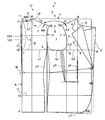
- mold of this invention The expanded view which shows the right half body part of the spine original type
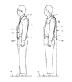
- Explanatory drawing which shows the measurement state of the length of a wearer's provisional left shoulder front and back base points N and M and the ground surface GL.
- Explanatory drawing of the base point setting measure Explanatory drawing of a height measurement measure.
- Explanatory drawing which suspended the loop-shaped base point setting measure from the wearer's neck.
- the perspective view of the measuring device of this invention The top view of the measuring device of this invention.
- Explanatory drawing of the state which uses the measuring device of this invention. Explanatory drawing of the state which uses the measuring device of this invention.
- Explanatory drawing of the state which uses the measuring device of this invention Explanatory drawing of the state which uses the measuring device of this invention.
- Explanatory drawing of the state which uses the measuring device of this invention Explanatory drawing of the state which uses the measuring device of this invention.
- Explanatory drawing which shows the measurement state of the length of the wearer's provisional left shoulder front and back base points N and M which use the measuring device of this invention, and the ground surface GL.
- Explanatory drawing which fine-tunes the position of the left shoulder back-and-front base points N and M according to the wearer's chest width and body shape of the back width. Step explanatory drawing showing the process of creating the prototype of the present invention
- This invention consists of a left half part and a right half part formed by dividing the outer jacket main body into left and right parts from the back center line of the back part, and a substantially elliptical shape formed by partially cutting the upper part of the center upper part of the left and right half parts.
- the left and right sleeve holes, the heel formed at the front edge of the left body part body, the chest width part in front of the sleeve hole part, the side width part below the sleeve hole part, and the back behind the sleeve hole part The upper part of the original centerline of the wearer's original back center line, formed by joining and sewing together the partially cut ends of the left and right cuffs and the back sewing lines of the left and right body parts.
- the present invention provides a broad-type prototype characterized by having been configured.
- the correction formula applied to the chest circumference from the back center line when specifying the left and right shoulder back base points is (0.15 to 0.20) about 1/2 of the chest circumference. It is intended to provide a prototype of the spine characterized by multiplication.
- the correction formula applied to the length around the neck from the back center line when specifying the length around the neck is (10-15) added to the length around the neck, and the total is calculated as
- the present invention provides a broad-type prototype characterized by dividing by (5-7). Further, the curved frame 100a that can be mounted and placed around the wearer's rear neck, left and right inclined plates 104 and 105 pivotally supported on the left and right ends of the curved frame 100a via the pivot 106, and the curved frame 100a are free.
- a ground height measuring device capable of measuring the length from the left and right shoulder front and rear base points (N, M) set on the end to the ground level GL, and the curved frame 100a includes a left half curved portion 101a and a right half
- the bent portion 102a is a separate body and the other bent portion 101a or 102a is a telescopic mechanism in which the base end can be freely inserted into the base end of one bent portion 101a or 102a.
- , M) are provided at the lower end of the upper half measurement measure 121 and the lower half of the upper half measurement measure 121 suspended from the back side or the chest side.
- a reflecting weight 122 that receives reflection.
- the embodiment of the spine prototype X of the present invention is basically formed by separating the outer body 100 from the wearer's original back center line 101 ′ on the back.
- the cutout end portions S of the sleeve hole 3 and the back center lines 101 of the left and right half body parts 1 and 2 are joined and sewn.
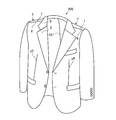
- the right and left shoulder front base point N and the right and left shoulder rear base point M are specified while correcting various measurement values on the shoulder portions of the left and right half body parts 1 and 2, and the left and right shoulder front base point N or the neck muscles.
- the line connected to the notch front end 35 of the cuff 3 from the reference point in the middle of the line is defined as the front shoulder ridge line 6, and the shoulder M from the left and right shoulder rear base point M or the reference point in the middle of the neck line
- a line connected to the notch rear end portion 36 of the sleeve hole portion 3 at an inclination angle ⁇ ′ is referred to as a rear shoulder ridge line 7.
- the three-dimensional spine prototype X (shown in FIG. 4) is completed by joining and sewing the front shoulder ridge line 6 and the back shoulder ridge line 7.
- the left and right half parts 1 and 2 are basically composed of a front body I and a back body B.
- the front body is the front body and the rear body is the back body.
- the front and back bodies a and b are cut separately and then sewn together at a predetermined line.
- the stitching line between the front body a and the back body b is “front shoulder ridge line 6 and back shoulder ridge line 7” and “sewing allowance y4”. 1 is formed.
- step S1 (1) Identification of the virtual base point M ′ behind the left shoulder (steps S1, S2)
- the virtual base point M ′ behind the left shoulder is specified (steps S1 and S2).
- the point moved outward by the length multiplied by 0.1 is defined as the back base point O ′, and 1/2 P of the chest circumference from the back base point O ′ is multiplied by (0.177 ⁇ 0.005).
- This point is specified by moving forward by the length L1 and further vertically moving from the moving point m by a length L2 that is about 1/4 of the moving length (steps S1 and S2).
- the length around the wearer's neck is not limited to the length P of the wearer's chest circumference.
- the virtual base point N ′ in front of the left shoulder is (0.56 ⁇ 0.05) times the length L3 (FD) from the front edge 4 of the front body to the side width point D of the front edge of the cuff 3 This is a point specified by the intersection of the vertical line G of the vertical point g of the position and the absolute horizontal line v from the virtual base point M ′ behind the left and right shoulders.
- the back base point O ′ is made to correspond to the above human skeleton point, and the shoulder angle is measured around this point, and the virtual base points M ′ and M ′ behind the left and right shoulders and the virtual base point N ′ before the left and right shoulders in the embodiment.
- N ', and the actual correct base points M, N are determined from various measured values and correction values described later to create the left and right half parts 1, 2, so that the wearer feels the most burden when wearing the suit It is possible to create a prototype that fits the body shape of each person who has not.
- the seventh cervical vertebra is one of seven vertebrae, which can be confirmed by a long spinous process protruding backward with a tactile sensation.
- a spinous process of the first thoracic vertebra is one of seven vertebrae, which can be confirmed by a long spinous process protruding backward with a tactile sensation.
- Below the spinous process is a spinous process of the first thoracic vertebra.
- the upper spinous process (7th cervical vertebra) moves with the movement of the neck, but the lower spinous process (1st thoracic vertebra) does not move.
- the wearer wears the back because the wearer's original back center line 101 'is the base point O' of all dimensions.
- the wearer's original back base point O ′ is determined in consideration of the clear portion.
- the length between the back upper end O and the back base point O ′ is L1 ⁇ 0.1 (1/10).
- the base point setting measure 30 is composed of a loop-like string body 31 as shown in FIG. 9, and the center-point of the loop-like string body 31 obtained by virtually dividing the loop-like string body 31 is for the base point.
- the other point obtained by interposing the weight 32 and virtually dividing the string 31 into two equal parts, that is, a point located on the opposite side of the weight 32 is set as a reference point KP.
- a display scale 33 indicating a length such as mm or cm is displayed on one side of the center, ie, the reference point KP.
- the height measuring measure 40 includes a height weight 42 connected to one end of a long string body 41, and a long string body to indicate the length from the bottom surface of the weight 42.
- Reference numeral 41 denotes a height display scale 43 indicating a length such as mm or cm.
- the height weight 42 causes the tension of the long string body 41 when measuring the length from the ground surface to the temporary left and right shoulder front and rear base points N and M, and provides an accurate length dimension. It is for acquisition and performs the same function as the falling weight used for surveying civil engineering works.
- the height measurement measure 40 is an instrument that measures the length from the ground surface (GL) to the left and right shoulder front and rear points N and M by using the tension of the long string body 41 by using the height weight 42.
- the ground height measuring device 120 using the electronic device can be used so that it can be measured more easily and accurately.
- the measurement values using the base point setting measure 30 and the height measurement measure 40 configured as described above are used as shown in FIGS. 11 and 8 and are based on “temporary left and right shoulder front and rear points N and M”. It is used to correct the position of “right and left shoulder rear base point M and left and right shoulder front base point N” to fit the wearer's body shape, and finally right and left shoulder rear base point M and left and right shoulder front base point N The pattern U at the correct position is created.
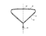
- a loop-shaped base point setting measure 30 is suspended from the wearer's neck.
- the base point weight 32 is positioned at the chest.
- This state is a state in which the loop-shaped string 31 is suspended from the neck to the chest, so to speak, the left and right lines 34, 34 of the loop-shaped string 31 trace the left and right lines of the suitcase.
- the string 31 locus is formed.
- the back base point GP of the string body 31 coincides with the position of the wearer's back base point O ′, that is, the position of the border center of the seventh cervical vertebra and the first thoracic vertebra.
- a temporary reference dimension of 9 cm is set as provisional temporary left and right shoulder rear base points M and left and right shoulder front base points N (naturally, the left and right shoulder rear base points M and the left and right shoulder front base points N are provisionally determined as one point coincident with each other) ( Step S4).
- the temporary reference dimension of 9 cm is the average standard dimension of the wearer.
- the position of the virtual base point M ′ behind the left and right shoulders is inevitably specified on the temporary pattern, and the temporary pattern is based on this.
- the length rcm of the neck line WN of the curved line between the back base point O ′ and the virtual base point M ′ behind the left and right shoulders (in other words, the left side from the reference point KP in the base point setting measure 30 suspended from the wearer's neck)
- the length to the position of the correct virtual base point M ′ that moves in the direction is calculated (step S3).
- the position of the length rcm of the neck line WN is the position of the virtual base point M ′ behind the left and right shoulders and the virtual base point N ′ before the left and right shoulders as measured by the wearer. Since the positions of the base point M ′ and the base point N ′ are calculated positions in the case of a wearer having an ideal upright and immobile standard body shape without any body or back, this base point M is determined by the peculiarity of the wearer's body shape. The work of correcting the position of ', base point N' to the right and left shoulder front and back base points N, M suitable for the wearer must be performed. This correction work will be described below.
- the position of the temporary reference dimension 9 cm in the body 31 is set as the “temporary left shoulder front and rear base points N and M”, which is set as the temporary left shoulder front and rear base points N and M in the temporary pattern U (step S4).
- the position of the virtual base point M ′ behind the left shoulder is set to (1 / 2P) of the actually measured wearer's chest circumference from the back base point O ′ as described in paragraph [0025]. 177 ⁇ 0.005) multiplied by the length L1 and further moved vertically from the moving point m by a length L2 that is about 1/4 of the moving length, or around the neck It is tentatively determined as a point determined by measurement.
- the neck line WN of the curved line is a string 31 of the base point setting measure 30 suspended from the neck.
- the position of the temporary reference dimension 9 cm of the neck line WN from the back base point O ′ is set as the position of the temporary left shoulder rear base point M on the wearer's left shoulder (step S4).
- the calculated length rcm of the neck line WN in the pattern U is an objective calculation length derived from the above measurement (calculation of paragraph number [0025]) from the actual measurement of the chest circumference of the wearer.
- this curved length rcm is a length from the back base point O ′ to the original correct left shoulder rear base point M in the loop-like string 31. It can be said that.
- the temporary left shoulder base M was initially assumed to be the position of the standard dimension 9 cm of the string 31, the position of the wearer's cooling, stoop, etc. was not taken into account. It is not the position of the original right shoulder rear base point M. Accordingly, it is necessary to determine which point of the wearer's body shape is the right and left base points N and M in consideration of the peculiarities such as the wearer's body and back.
- the wearer in order to determine the position of the original right shoulder rear base point M on the pattern U, the wearer starts from the ground surface (GL) at the position of the temporary left shoulder rear base point M set to the position of the reference dimension 9 cm of the string 31.
- the length is measured on the back side and the chest side (step S6).
- the length from the ground surface (GL) to the temporary left and right shoulder rear base point M and the temporary left and right shoulder front base point N is measured by the height measurement measure 40, and this is performed as follows. That is, the length ⁇ from the ground surface (GL) to the temporary left and right shoulder rear base point M is measured on the back side (rear side) of the wearer, and the length from the ground surface (GL) to the temporary left and right shoulder front base point N is measured. Is measured on the chest side (front side) of the wearer (step S6).
- the length ⁇ from the ground surface (GL) to the temporary left and right shoulder rear base point M and the temporary left and right shoulder front base point N are measured.
- the length ⁇ can be measured, and the structure of the ground height measuring device 120 is configured as follows.
- the length ⁇ from the ground surface (GL) to the temporary left and right shoulder rear base point M is measured along the back side (rear side) of the wearer, and the temporary left and right front base point from the ground surface (GL).
- the length ⁇ up to N is for measuring the length along the chest side (front side) of the wearer.
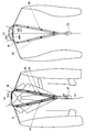
- the curved frame 100a used for measuring the inclination angle of the shoulder of the wearer described above is used. To do.
- the curved frame 100a is placed on the wearer's rear neck K, and the free end of the curved frame 100a is placed on the temporary left and right shoulder front and rear base points (N, M ) And the right and left free end positions 100a ′ of the curved frame 100a when the curved frame 100a is attached to the neck.
- 100a ′′ that is, ground height measurement using electronic equipment to measure the length ⁇ , ⁇ along the back and chest from the temporary left and right shoulder front and back base points (N, M) position to the ground surface (GL)
- An apparatus 120 can be used.
- the ground height measuring device 120 is configured by connecting the upper end of the upper half measurement measure 121 to the left and right free ends of the curved frame 100 a and providing the weight 122 with reflection function at the lower end of the measure 121.
- the upper half measurement measure 121 is made of a flexible last material so as to follow the wearer's back and chest, and the lower end of the flexible upper half measurement measure 121 is substantially in the middle of the chest side or the back side. It has a short length and is suspended downward from the temporary left and right shoulder front and rear base points (N, M).
- the reflecting function-provided weight 122 is provided with a transmitting section 124-1 for reflecting infrared rays, ultrasonic waves, and the like and a receiving section 124-2 for receiving these reflections on the lower end surface of the weight case 123. Accordingly, if the length of the upper half measurement measure 121 is set to a short length in advance, for example, set to 1 m, the measure 121 is moved from the temporary left and right shoulder reference points (N, M) to the chest and back of the wearer. It is easy to hang along the surface, and then the reflection time from the ground surface (GL) such as infrared rays transmitted from the reflection function vertical weight 122 at the lower end of the measure 121 is measured to measure the ground from the reflection function vertical weight 122.
- GL ground surface
- the distance to the upper surface (GL) will be measured, and the length obtained by adding the 1 m length of the upper half measurement measure 121 to this distance is the wearer's temporary left and right shoulder front and rear base points (N, M)
- the length ⁇ or ⁇ reaches the ground surface along the chest side or back side of the wearer. That is, the length from the temporary left and right shoulder front and rear base points (N, M) to the ground surface (GL) along the chest side and back side of the wearer is simply and easily and accurately measured by the short upper half measurement measure 121. Can be measured.
- step S7 the difference (difference between ⁇ and ⁇ ) is obtained, and the difference between ⁇ and ⁇ is used for correcting the position of the temporary left shoulder front base point M (step S7).
- this 0.5 cm difference (LX) is used as an increase / decrease factor of ⁇ and ⁇ measured at the position of the temporary left shoulder rear base point M (position of the reference dimension 9 cm of the string 31) (step S7).
- the position of the left shoulder front base point N is determined from the front body front edge 4 to the side edge D of the front edge of the cuff 3 as described in paragraph [0026].
- the ground height ( ⁇ ) of the temporary left shoulder rear base point M is corrected, and the upper part of the back body is extended upward or shortened downward due to the body shape.
- a correction is made to the ground height ( ⁇ ) of the temporary left shoulder base N, and the upper part of the front body i is expanded and contracted upward and downward by the correction amount. Therefore, for the first time, the correct left and right shoulder bases N and M are specified.
- the shoulder inclination angles ⁇ and ⁇ ′ are measured from provisional base points M and N at a preset reference dimension of 9 cm. That is, a constant adjustment angle from the left shoulder front base point N, that is, a line connected to the notch front end portion of the cuff 3 with the shoulder inclination angle ⁇ is defined as the left front shoulder ridge line 6, and a constant adjustment angle from the left shoulder rear base point M. That is, the line connecting the shoulder end angle ⁇ ′ and the notch rear end portion of the sleeve hole portion 3 is defined as the left and right rear shoulder ridge lines 7 (step S8).
- the measurement timing of the shoulder inclination angle has been described in the present embodiment at the timing of step S8 in FIG. 20, it may be measured, for example, between steps S4 and S5 in FIG. That is, the shoulder inclination angles ⁇ and ⁇ ′ may be measured after setting a point having a reference dimension of 9 cm as the temporary base points M and N.
- the front shoulder ridge line 6 with a constant inclination angle ⁇ from the left shoulder front base point N and the rear shoulder ridge line 7 with a constant inclination angle ⁇ ′ from the left shoulder rear base point M have an adjustment angle of 23 degrees in a normal standard angle. Actually, it is determined by measuring the wearer's shoulder line with a measuring instrument such as a protractor.
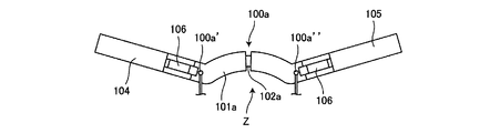
- the inventor has devised a measuring instrument Z that can be measured easily and accurately when measuring the shoulder line of the wearer with a measuring instrument such as a protractor. That is, as shown in FIGS. 12 to 14, first, a curved frame 100a that can be mounted and placed around the rear neck of the wearer is provided, and both ends 100a ′ and 100a ′′ of the curved frame 100a are temporarily specified left shoulders. Corresponding to the positions of the M and N coincidence points where the rear base point M and the left shoulder front base point N coincide with each other, and the positions of the right shoulder rear base point M and the right shoulder front base point N which are tentatively specified, respectively. Configure as follows.
- the curved frame 100a Since the positions of the left and right M and N points are displaced from side to side depending on the wearer's skeleton, shoulder width, etc., the curved frame 100a has a structure that can be expanded to the left and right. For example, the left half-curved portion 101a and the right half-curved point Separate from the portion 102a, the other bent portion 101a or 102a can be inserted into the base end of one bent portion 101a or 102a.
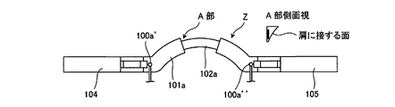
- the cross-sectional shape of the curved frame 100a can be placed around the rear neck as a slightly inclined curved surface wx as shown in the side view of part A shown in FIG. 14 so that the lower end surface can be placed around the rear neck of the wearer. Make the shape as close as possible.
- left and right inclined plates 104 and 105 for measuring the inclination angle of the shoulder ridge line are connected to the left and right ends of the curved frame 100a so as to be freely slidable. That is, the base ends of the left and right inclined plates 104 and 105 are pivotally supported via the pivot 106 at the left and right ends of the curved frame 100a. Since the left and right inclined plates 104 and 105 are pivoted about the pivot 106, the measurement scale 107 for measuring the tilt angle from the absolute horizontal position at the portion of the pivot 106 in order to measure the absolute tilt angle due to the swing. Is attached. The measurement scale 107 is provided with a horizontal leveler (not shown).
- the horizontal leveler 103 is configured to detect the absolute horizontal position, and the inclination angle is detected by converting from the absolute horizontal position.
- a digital display unit is provided in place of the measurement scale 107, and the tilt angle is determined by electrically detecting the peristalsis of the left and right inclined plates 104 and 105. It can also be configured to display on a digital display.
- a power source unit, a control unit, and a leveler mechanism are built in the curved frame 100a, and the movement of the left and right inclined plates 104 and 105 is electrically detected, and the inclination angle of the left and right inclined plates 104 and 105 is displayed. It is comprised as follows.
- the curved frame 100 a is placed on the wearer's rear neck muscle K, and the left and right shoulder rear base points M and M and the left and right shoulder front base points N are placed on the left and right ends of the frame 100 a.
- the left and right inclined plates 104 and 105 are placed on the left and right shoulder ridge lines from the positions of the left and right shoulder rear base points M and M and the left and right shoulder front base points N and N, respectively.
- the inclination angles of the left and right inclined plates 104 and 105 tilting as the center are measured by a measurement scale 107 or an electrical detection method.
- bust line B About bust line B, waist line W, hip line H, hem line J
- the left half part 1 forms bust line B, waist line W, hip line H, and hem line J at a fixed distance from the upper edge. ing.
- the vertical length of O ′ to C is the height K.
- the back base point O ′ is set at a point obtained by multiplying 1/2 P of the chest circumference by about 0.15 and about 0.1.
- a 2 cm clearance y2 is formed from the bust point C of the bust line B.
- C ′ bust clearance point
- C ′ clearance point
- y1 clearance y1 from the bust point C of the bust line B
- the lateral width of C ′ to E is the back width portion b1. From the back width point E of the rear edge position of the sleeve hole portion 3 in the bust line B to the point of the length obtained by multiplying 1/2 P of the chest circumference by about 0.25, that is, the front edge of the sleeve hole portion 3. The point is the side width point D, and the lateral width of D to E is the side width part b2.
- the button position on the front edge of the front body a of the outer body 100 is the button point F, and the width obtained by multiplying 1 / 2P of the chest circumference by about 0.37 is the horizontal width of DF.
- a point having a length obtained by multiplying the length of D to F by about 0.56 in the middle of D to F is defined as a vertical point g, and the upper end of the vertical line G of the vertical point g is the left shoulder front base point N. .
- the waist line W is an intermediate point between the bust line B and the hip line H, that is, a horizontal line of the waist point I of (B to H) ⁇ 1/2.
- the hip line H is a horizontal line at the hip Q point having a length obtained by multiplying the length from the back base point O ′ to the hem line J by about 0.184.
- y5 is a front dart which shows the clearance below a heel in the figure.
- R represents a breast pocket.
- Reference numeral 5 ′ denotes a neck collar portion that is continuously provided and stitched to the upper end portion of the collar portion 5, and is continuously stitched to the upper end portion (5 ′′) of the back width portion b 1 other than the front and rear shoulder ridge lines 6 and 7.
- the hem line J has a front hem line J1 descending about 1.5 cm, and the hem line J looks generally horizontal when worn, so that the overall appearance of the suit is good.
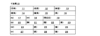
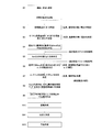
- FIG. 7 shows a dimension table 10 for entering measurement dimensions, and the following columns are provided. That is, Measurement date and time column 11, wearer's name column 12, body type column 13 describing the distinction and dimensions of the body and the body, A column 14 for entering the shoulder inclination angle from the left and right shoulder front base point N, a column 15 for entering the shoulder inclination angle from the left and right shoulder rear base point M, A column 16 for entering an average angle obtained by multiplying the sum of the tilt angle from the left and right shoulder front base point N and the tilt angle from the left and right shoulder rear base point M by 1/2; In order to specify the left and right shoulder base N, the N point dimension column 17 for entering a number obtained by multiplying the length L of (F to D) and (0.56 ⁇ 0.05), To specify the left and right shoulder rear base point M, enter the number L1 obtained by multiplying 1/2 of the chest circumference length P by (0.177
- M point dimension column 18 A height dimension column 19 for entering the length from the back base point O ′ to C located at the lower side by a length obtained by multiplying 1 / 2P of the length of the chest circumference by 0.45, Chest circumference dimension column 20 for entering a numerical value obtained by adding a margin dimension as a space to the actual chest circumference P ′, A chest width column 21 for entering the dimensions of the chest width portion b3 in the bust line B actually measured; Side width column 22 for entering the dimensions of side width part b2 in bust line B, A back width column 23 for entering the dimensions of the back width portion b1 in the bust line B; Waist dimension column 24 for entering dimensions in the waist line W, Waist width column 25 for entering the width dimension of the front body a in the waistline W, Waist rear width column 26 for entering the width dimension of the back body in the waistline W, Hip front width column 27 for entering the actual measurement in the hip line H, Front hip width column 28 for entering the width of the front body a in the hip line H, Hip
- the base point setting measure 30 is then suspended from the neck, and the position of the length rcm of the left neck line WN is taken from the reference point KP, so For non-exemplary standard body wearers this is necessarily the position of the correct left shoulder back origin M (N) in the wearer's body.
- the height measurement measure 40 measures the length of the back side and the chest side from the ground surface (GL), and ⁇ and ⁇ are calculated. put out.
- the trace t1 of the curved length of the curved neck line WN from the back base point O ′ and the actually measured scale length from the ground surface (GL) to the left shoulder rear base point M Let the intersection with the locus t2 be the correct position of the left shoulder rear base point M in the pattern U.
- the position calculation method (paragraph) of the virtual base point M' behind the left shoulder according to the inventor's many years of tailoring results
- the virtual base point M ′ behind the left shoulder is determined from the number [0025]), and the correct base point M behind the left shoulder on the wearer's original body is further added to the values of ⁇ and ⁇ measured by the base point setting measure 30.
- the position of the virtual base point M ′ after the left shoulder calculated from the chest circumference is corrected, and the correct left shoulder base point M on the pattern U is specified.
- the right and left shoulder bases N and M and the right shoulder front and rear base points N and M are determined to be optimal positions that match various body types such as the back, crouch, shoulder, and shoulder. It is possible to balance the balance between the left and right sides of the base point O ′ (swing action), and it is possible to provide a smart and comfortable suit with respect to appearance and wearer activity.
- “Yajirobee” is configured so that the center point is set and balanced by the weights on the left and right sides. Hold.
- the spine is based on the shoulder inclination angles ⁇ and ⁇ ′ from the left and right shoulder front and rear base points N and M, the back side length ⁇ and the ground surface (GL) from the ground surface (GL) to the left and right shoulder front and rear base points N and M.
- the left / right front / rear base points N and M have the same left / right balance function as “Yajirobe” centered on the back base point O ′ when the length ⁇ on the chest side matches the body shape of the suit wearer. And it becomes a suit that fits the wearer most in terms of appearance and comfort (steps S11 and S12).
- the front body and the back part of the body must be It should be noted that the width of the is different from that of a standard size wearer.
- the positions of the left and right shoulder front and rear base points N and M are finely adjusted according to the wearer's chest width and back width body shape. If N and M are moved in parallel, vertical movement occurs in the front body i and back body b. That is, new left and right shoulder front and rear base points N-1 and M-1 obtained by finely adjusting the left and right shoulder front and rear base points N and M by parallel translation by the length of ⁇ (for example, 5 mm) in the dimensional diagram of the pattern shown in FIG. A pattern is created by collecting various dimensions as reference points.
- the area of the front body i will be increased accordingly and Exercise occurs.
- the left and right shoulder rear base point M is moved 5 mm to the right as shown in FIG. 19 to be a new left and right shoulder rear base point M-1
- the area of the rear body B will be increased accordingly, and upward movement will occur in the front body i.
- the left and right shoulder front base point N is moved 5 mm to the right as shown in FIG. 19 to be a new left and right shoulder front base point N-1
- the area of the front body a becomes narrower and the downward movement occurs in the front body a.
- left and right shoulder rear base point M is moved 5 mm to the left as shown in FIG. 19 to be a new left and right shoulder rear base point M-1, the area of the back body will be reduced accordingly, and downward movement will occur in the back body .
- the left and right shoulder front and back base points N and M are finely adjusted by moving by the length of ⁇ , and the chest width and back width are adjusted by using the new left and right shoulder front and rear base points N-1 and M-1 as reference points.
- an important back base point O ′ can be determined by “sagging” (swinging action), and a comfortable suit that fits the body shape can be provided.
- This "Yajirobe” (swing action) occurs not only on the left and right sides of the shoulder but also on the front and rear of the shoulder.
- the swing is centered on the back base point O 'in the lateral and lateral directions and the front and rear direction around the shoulder. Since the spine prototype is tailored in the state of action, it is possible to provide a comfortable suit that fits the wearer's body shape.
Abstract
Description
このように裁断することによって袖部分を肘を軽く曲げて腕を斜め下前方に出した状態の曲線に近い立体形状を形成し、腕の前後左右の運動に対して着用感が良好な上着としている。 In the patent No. 4537553, the arm member connected to the upper part of the front body and the back body is divided into a forearm member, a rear arm member, and a lower arm member, and the sleeve is made of at least three members, and the shape of each arm member Is curved in a certain direction, or the side edge part attached to the front body and the back body intersects at an acute angle, and the intersection of the acute angle becomes a buttock to form a necessary space for exercise in the sewing state .
By cutting in this way, the sleeve part is lightly bent at the elbow to form a three-dimensional shape close to the curve of the arm protruding diagonally downward and forward, and the outerwear has good wearing feeling with respect to the movement of the arm front and rear, left and right It is said.
すなわち、着用状態での着用者の体型的諸条件、例えば身長や、背の前後傾(猫背、反身)や、左右の肩の上下バランス等の諸条件に合致し、着用者の体型的特徴にフィットする背広を縫製することができない。 However, in the sewing of outerwear by such sewing patterns and disassembly patterns of the sleeve part, although it is certainly excellent in comfort and ease of exercise, the style that is regarded as most important with respect to outerwear such as suits and jackets There is a difficulty in this point.
That is, it conforms to various conditions of the wearer's body shape, such as height, tilting the back and forth (back and back), vertical balance of the left and right shoulders, and so on. A suit that fits cannot be sewn.
また、左右肩後基点を特定する際に背中心線から、胸囲の長さに対して適用する修正公式とは、胸囲の長さの約1/2に(0.15~0.20)を乗じることを特徴とする背広原型を提供するものである。
また、首回りの長さを特定する際に背中心線から、首周りの長さに対して適用する修正公式とは、首周りの長さに(10~15)を加算し、その合計を(5~7)で除することを特徴とする背広原型を提供するものである。
さらに、着用者の後首まわりに沿って装着載置可能な弯曲フレーム100aと、
弯曲フレーム100aの左右端部に枢軸106を介して枢支した左右傾斜板104,105と、弯曲フレーム100aの自由端部上に設定される左右肩前後基点(N,M)から地上面GLまでの長さを測定可能な地上高計測装置と、を備え、弯曲フレーム100aは、左半弯曲部101aと右半弯曲部102aとを別体とし、一方の弯曲部101a又は102a基端中に他方の弯曲部101a又は102aを基端を差し込み自在な伸縮機構とし、地上高計測装置は、左右肩前後基点(N,M)から背中側又は胸側下方に吊り下げられる上半部測定メジャー121と、上半部測定メジャー121の下端に設けられ、赤外線を地上面GLに照射し地上面GLからの反射を受信する反射機能付垂錘122と、を有することを特徴とする背広原型用測定器である。 This invention consists of a left half part and a right half part formed by dividing the outer jacket main body into left and right parts from the back center line of the back part, and a substantially elliptical shape formed by partially cutting the upper part of the center upper part of the left and right half parts. The left and right sleeve holes, the heel formed at the front edge of the left body part body, the chest width part in front of the sleeve hole part, the side width part below the sleeve hole part, and the back behind the sleeve hole part The upper part of the original centerline of the wearer's original back center line, formed by joining and sewing together the partially cut ends of the left and right cuffs and the back sewing lines of the left and right body parts. From the back base point to be moved, it moves forward by a length calculated by applying a pre-defined correction formula to the length of the chest circumference or the length around the neck, and from the moved point to about 1/4 of the movement length The point identified by moving vertically up the length of The point specified by the intersection of the vertical line approximately 0.5 to 0.6 times the length from the front edge to the front edge of the cuff and the absolute horizontal line from the virtual base point behind the left and right shoulders The length of the curved neck line from the back base point of the back of the back to the virtual base point before and after the left and right shoulders and the standard temporary reference point specified in the middle of the neck line The length from the reference point specified in the middle of the neck line using the difference value to the ground level passing through the back of the wearer's body and the length from the chest side to the ground level The correct left and right shoulder front and rear base positions are determined by correcting each and the correct right and left shoulder front base points, or a line connected to the notch front end of the cuff with a certain adjustment angle from the reference point in the middle of the neck line The right and left front shoulder ridge lines The lines connecting the rear base point or the reference point in the middle of the neck line with the respective shoulder inclination angles and the notch rear end of the cuffs are the left and right rear shoulder ridge lines, and the front shoulder ridge line and the rear shoulder ridge line are stitched together. The present invention provides a broad-type prototype characterized by the above.
The correction formula applied to the chest circumference from the back center line when specifying the left and right shoulder back base points is (0.15 to 0.20) about 1/2 of the chest circumference. It is intended to provide a prototype of the spine characterized by multiplication.
The correction formula applied to the length around the neck from the back center line when specifying the length around the neck is (10-15) added to the length around the neck, and the total is calculated as The present invention provides a broad-type prototype characterized by dividing by (5-7).
Further, a
Left and right
すなわち、背広原型を作成する際に、実際の着用者の胸囲などから計算した湾曲状の首筋ラインの計算上の数値や、首筋ライン中途部の標準的な仮の基準地点から身体前後面を通過した地上面までの距離の長さなどの各種要素を用いることを特徴としており、かかる手法により、着用者の身体的体型がいかに異なっても、常に背基点を中心として人体の肩の左右及び人体の肩前後がそれぞれ「やじろべえ」の均衡した姿勢となり、着心地の最良な背広原型を提供できるようにしたものである。 As described above, the basic idea of the present invention is to measure the length of the chest circumference or neck that is an objective numerical value of the wearer, apply the correction formula to it, The virtual base points around the left and right shoulders are set at a certain distance and place from the back base point. By adding the length of the neck line and the distance between the temporary reference point specified in the middle of the neck line and the ground surface passing through the front and back of the body to the position of this virtual base point, Correct the position of the shoulder front and back base points to the correct position, and set the right and left shoulder front and rear base points on the pattern. The basic idea is to set each point of the pattern required for the spine prototype using the right and left shoulder front and back base points as the origin of all dimensions.
In other words, when creating the prototype of the back, the calculated value of the curved neck line calculated from the chest circumference of the actual wearer, etc., and the body front and back surfaces from the standard temporary reference point in the middle of the neck line It is characterized by the use of various elements such as the length of the distance to the ground surface, and by this method, no matter how the wearer's physical shape is different, the left and right of the shoulder of the human body and the human body are always centered on the back base point. The front and back shoulders have balanced “Yajirobe” postures, so that they can provide the best model with the best comfort.
特に、首筋ラインに沿った背基点からの長さを基準にして左右肩前後基点を仮に特定し、その後地上面からの長さを測定してこの測定値を修正しながら正しい左右肩前後基点を特定し、この正しい左右肩前後基点を背広原型に必要な各種寸法の基準点としたため、背広の左右肩が背基点を中心として「やじろべえ」の原理を用いたバランスのとれた形態となり着用者のいかなる体型にもフィットすることができる効果がある。 The garment made with such a stencil prototype fits the wearer's body precisely and has a shoulder that is easy to act on, so the left and right arms do not cause unnecessary wrinkles near the back of the neck or around the shoulder when worn. There is an effect that it is possible to provide a wearing posture of a smart suit that adapts to the movement of the person.
In particular, the right and left shoulder front and back base points are temporarily identified based on the length from the back base point along the neck line, and then the right and left shoulder front and rear base points are corrected while measuring the length from the ground surface and correcting this measurement value. Since the right and left shoulder front and back base points were used as the reference points for the various dimensions required for the prototype, the left and right shoulders of the back became a balanced form using the principle of `` Yajirobe '' centered on the back base point. There is an effect that can fit any body shape.
また、左右肩後基点を特定する際に背中心線から、胸囲の長さに対して適用する修正公式とは、胸囲の長さの約1/2に(0.15~0.20)を乗じることを特徴とする背広原型を提供するものである。
また、首回りの長さを特定する際に背中心線から、首周りの長さに対して適用する修正公式とは、首周りの長さに(10~15)を加算し、その合計を(5~7)で除することを特徴とする背広原型を提供するものである。
さらに、着用者の後首まわりに沿って装着載置可能な弯曲フレーム100aと、 弯曲フレーム100aの左右端部に枢軸106を介して枢支した左右傾斜板104,105と、弯曲フレーム100aの自由端部上に設定される左右肩前後基点(N,M)から地上面GLまでの長さを測定可能な地上高計測装置と、を備え、弯曲フレーム100aは、左半弯曲部101aと右半弯曲部102aとを別体とし、一方の弯曲部101a又は102a基端中に他方の弯曲部101a又は102aを基端を差し込み自在な伸縮機構とし、地上高計測装置は、左右肩前後基点(N,M)から背中側又は胸側下方に吊り下げられる上半部測定メジャー121と、上半部測定メジャー121の下端に設けられ、赤外線を地上面GLに照射し地上面GLからの反射を受信する反射機能付垂錘122と、を有することを特徴とする。 This invention consists of a left half part and a right half part formed by dividing the outer jacket main body into left and right parts from the back center line of the back part, and a substantially elliptical shape formed by partially cutting the upper part of the center upper part of the left and right half parts. The left and right sleeve holes, the heel formed at the front edge of the left body part body, the chest width part in front of the sleeve hole part, the side width part below the sleeve hole part, and the back behind the sleeve hole part The upper part of the original centerline of the wearer's original back center line, formed by joining and sewing together the partially cut ends of the left and right cuffs and the back sewing lines of the left and right body parts. From the back base point to be moved, it moves forward by a length calculated by applying a pre-defined correction formula to the length of the chest circumference or the length around the neck, and from the moved point to about 1/4 of the movement length The point identified by moving vertically up the length of The point specified by the intersection of the vertical line approximately 0.5 to 0.6 times the length from the front edge to the front edge of the cuff and the absolute horizontal line from the virtual base point behind the left and right shoulders The length of the curved neck line from the back base point of the back of the back to the virtual base point before and after the left and right shoulders and the standard temporary reference point specified in the middle of the neck line The length from the reference point specified in the middle of the neck line using the difference value to the ground level passing through the back of the wearer's body and the length from the chest side to the ground level The right and left shoulder front and rear base points were identified by correcting each of the two points, and the correct right and left shoulder front base points were connected to the front end of the notch of the cuffs with a certain adjustment angle from the reference point in the middle of the neck line. Correct left to right with left and right front shoulder ridge lines corrected The line connected to the rear edge of the notch of the cuff with the inclination angle of each shoulder from the reference point in the middle of the back of the shoulder line or the neck line is the left and right back shoulder ridge line, and the front shoulder ridge line and the back shoulder ridge line are joined and sewn The present invention provides a broad-type prototype characterized by having been configured.
The correction formula applied to the chest circumference from the back center line when specifying the left and right shoulder back base points is (0.15 to 0.20) about 1/2 of the chest circumference. It is intended to provide a prototype of the spine characterized by multiplication.
The correction formula applied to the length around the neck from the back center line when specifying the length around the neck is (10-15) added to the length around the neck, and the total is calculated as The present invention provides a broad-type prototype characterized by dividing by (5-7).
Further, the
まず最初に左肩後の仮想基点M´の特定(ステップS1,S2)を行う。
左肩後の仮想基点M´は、背中部分の背中心線101上端に位置する点を背上端Oとし、胸囲の長さの1/2(=P)に(0.177±0.005)を乗じ更に0.1を乗じた長さだけ外方に移動した点を背基点O´とし、背基点O´から胸囲の長さの1/2Pに(0.177±0.005)を乗じた長さL1だけ前方へ移動し、更に移動点mから移動長さの約1/4の長さL2だけ上方に垂直に移動して特定した点である(ステップS1,S2)。
なお、仮の型紙Uにおいて、左肩前の仮想基点M´を特定する計測方法を説明したが、このように着用者の胸囲の長さPを基準とする以外にも着用者の首回りの長さPPを基準にする方法もある。
すなわち、首回りの長さPPに「13」を加算し、その合計を6で除した数字をL1とし、L1のm点からL1の4分の1の長さL2だけ上方に垂直に移動して、特定した点を左肩後の仮想基点M´とすることもできる。
すなわち、L1=(PP+13)÷6、L2=L1×1/4とする(ステップS1,S2)。 (1) Identification of the virtual base point M ′ behind the left shoulder (steps S1, S2)
First, the virtual base point M ′ behind the left shoulder is specified (steps S1 and S2).
The virtual base point M ′ behind the left shoulder is the point located at the upper end of the
Although the measurement method for specifying the virtual base point M ′ in front of the left shoulder in the temporary pattern U has been described, the length around the wearer's neck is not limited to the length P of the wearer's chest circumference. There is also a method based on the PP.
That is, add “13” to the length PP around the neck, and divide the total by 6 to L1, and move vertically from the m point of L1 by a length L2 that is a quarter of L1. Thus, the specified point can be set as the virtual base point M ′ behind the left shoulder.
That is, L1 = (PP + 13) ÷ 6 and L2 = L1 × 1/4 (steps S1 and S2).
背基点O´の位置は人体の骨格に対応させると、第7頚椎と第1胸椎の境の中央部分の点の位置とする。 (2) Identification of the back base point O ′ When the position of the back base point O ′ is made to correspond to the skeleton of the human body, the position of the center portion of the boundary between the seventh cervical vertebra and the first thoracic vertebra is set.
ここで、背中心線101の上端の背上端Oを用いるのではなく、着用者の本来の背中心線101´の背基点O´をすべての寸法の基点としたのは着用者が背広を着用した場合に、背中部分は左右湾曲面となっているため、湾曲面形成のためのゆとり部分を取る必要があり、そのため着用者本来の背基点O´をゆとり部分考慮の上で定めている。背上端Oと背基点O´との間は、L1×0.1(1/10)の長さとする。 Thus, by moving the cervical part, the moving spinous process and the non-moving spinous process can be confirmed with fingers, and the position of the seventh cervical vertebra and the position of the first thoracic vertebra can be specified from outside the human body.
Here, instead of using the back upper end O at the upper end of the
そこで、着用者にとって最も着心地良好な背広の各種寸法の基準となる本来の「正しい左右肩後基点Mと左右肩前基点N」を決定するために、本実施例では着用者の身体の測定を行い仮想基点M´,M´及び仮想基点N´,N´を決定し、同時に標準的な基点としての「仮の左右肩後基点Mと左右肩前基点N」を設定し、これらの各基点を基にして各種の修正や要因を付加して「正しい左右肩後基点Mと左右肩前基点N」を導くという方法を採用した。
そのために、基点設定メジャー30と高さ測定メジャー40との二種類の器具を準備する。 (3) Specific method of the right and left shoulder front and back base points N and M (a) The positions of the virtual base points M ′ and M ′ after the left and right shoulders determined by the above method and the virtual base points N ′ and N ′ before the left and right shoulders are The wearer is a position in a standard or exemplary body shape that does not have a special body shape such as anti-reverse and lean. Therefore, the correct left and right shoulder front and rear base points N and M are specified at this position by making modifications that match the individual body shape of the wearer. Must be done.
Accordingly, in order to determine the original “right and left shoulder rear base points M and left and right shoulder front base points N”, which are the basis for various dimensions of the suit that is most comfortable for the wearer, in this embodiment, measurement of the wearer's body is performed. To determine virtual base points M ′ and M ′ and virtual base points N ′ and N ′, and simultaneously set “provisional left and right shoulder back base points M and left and right shoulder front base points N” as standard base points. Based on the base point, various corrections and factors were added to derive the “right and left shoulder rear base point M and left and right shoulder front base point N”.
For this purpose, two types of instruments, a base
高さ用重錘42は、後述するように地上面から仮の左右肩前後基点N,Mまでの長さを計測する際に長尺紐体41の張力を生起し、正確な長さ寸法を取得するためのものであり、土木工事の測量に使用する落下重錘と同様の機能を果す。
高さ測定メジャー40は、高さ用重錘42を用いることにより長尺紐体41の張力を利用して地上面(GL)から左右肩前後地点N,Mまでの長さを計測する器具であるが、後述するようにより簡便に、かつ正確に計測できるように電子機器を用いた地上高計測装置120を使用することができる。 As shown in FIG. 10, the
As will be described later, the
The
(c)以下に、「仮の左右肩前後地点N,M」を基点設定メジャー30や高さ測定メジャー40を使用することにより着用者の特殊体型に合致した「正しい左右肩前後地点N,M」に修正する手順を説明する。
まず最初に、着用者の首にループ状の基点設定メジャー30を吊下する。この際、基点用重錘32が胸元に位置する状態とする。
この状態は、ループ状の紐体31が首から胸元にかけて配置吊下された状態であり、いわば背広の衿の左右ラインをループ状の紐体31の左右ライン34,34がなぞったV字形の紐体31軌跡が形成されたことになる。
この状態において、紐体31の背基点ポイントGPは、着用者の背基点O´の位置、すなわち骨格の第7頚椎と第1胸椎の境中央部の位置と一致している。 In addition, when measuring a wearer's body with the base
(C) “Temporary left and right shoulder front and back points N and M” are set to the “correct right and left shoulder front and rear points N and M that match the wearer's special body shape by using the
First, a loop-shaped base
This state is a state in which the loop-shaped
In this state, the back base point GP of the
なお、仮の基準寸法の9cmは、平均的な着用者の仮の標準寸法である。 (D) Next, in the
The temporary reference dimension of 9 cm is the average standard dimension of the wearer.
この首筋ラインWNの長さrcmの位置が着用者に対する実測による左右肩後の仮想基点M´及び左右肩前の仮想基点N´の位置である。
この基点M´,基点N´の位置は反身や猫背のない理想的な直立不動の標準体型を有する着用者の場合の計算上の位置であるため、着用者の体型の特殊性によりこの基点M´,基点N´の位置を着用者本人に適合した正しい左右肩前後基点N,Mに修正する作業を行わねばならない。この修正作業を以下に説明する。 That is, by measuring 1 / 2P of the length of the chest circumference of the wearer, the position of the virtual base point M ′ behind the left and right shoulders is inevitably specified on the temporary pattern, and the temporary pattern is based on this. The length rcm of the neck line WN of the curved line between the back base point O ′ and the virtual base point M ′ behind the left and right shoulders (in other words, the left side from the reference point KP in the base
The position of the length rcm of the neck line WN is the position of the virtual base point M ′ behind the left and right shoulders and the virtual base point N ′ before the left and right shoulders as measured by the wearer.
Since the positions of the base point M ′ and the base point N ′ are calculated positions in the case of a wearer having an ideal upright and immobile standard body shape without any body or back, this base point M is determined by the peculiarity of the wearer's body shape. The work of correcting the position of ', base point N' to the right and left shoulder front and back base points N, M suitable for the wearer must be performed. This correction work will be described below.
従って、着用者の反身、猫背などの特殊性を考慮して着用者の体型のどの地点が正しい左肩前後基点N,Mであるかを決定する必要がある。 However, since the temporary left shoulder base M was initially assumed to be the position of the standard dimension 9 cm of the
Accordingly, it is necessary to determine which point of the wearer's body shape is the right and left base points N and M in consideration of the peculiarities such as the wearer's body and back.
なお、高さ測定メジャー40の代わりに前述の地上高計測装置120を用いて、地上面(GL)から仮の左右肩後基点Mまでの長さαと、仮の左右肩前基点Nまでの長さβを計測することができるものであり、地上高計測装置120の構造は次のように構成されている。 The length from the ground surface (GL) to the temporary left and right shoulder rear base point M and the temporary left and right shoulder front base point N is measured by the
In addition, using the above-described ground
すなわち、測定器Zにより肩稜線の傾斜角度を測定するに際に弯曲フレーム100aを着用者の後首筋Kに定置し、弯曲フレーム100aの自由端部を、仮の左右肩前後基点(N,M)に合わせて定置して左右傾斜板104,105の搖動角度により肩稜線の角度を測定するものであるから、かかる弯曲フレーム100aの首筋装着状態において、弯曲フレーム100aの左右自由端部位置100a´,100a´´、すなわち仮の左右肩前後基点(N,M)位置から地上面(GL)までの背・胸部に沿った長さα,βを測定するために電子機器を用いた地上高計測装置120を用いることができる。
地上高計測装置120は、弯曲フレーム100aの左右自由端部に、上半部測定メジャー121の上端を連設し、該メジャー121の下端に反射機能付垂錘122を設けて構成している。
上半部測定メジャー121は着用者の背、胸部に沿うように可撓姓素材により構成し、かかる可撓性の上半部測定メジャー121は下端が略胸側或は背中側の途中に至る短尺の長さとしており、仮の左右肩前後基点(N,M)から下方に吊下される。
反射機能付垂錘122は垂錘ケース123下端面に赤外線や超音波等を反射する発信部124-1とこれらの反射を受信する受信部124-2とが設けられている。
従って、予め上半部測定メジャー121の長さを短尺に設定、例えば1mに設定しておけば、この該メジャー121を仮の左右肩前後基点(N,M)から着用者の胸部や背中部に沿って吊下しやすく、次いで該メジャー121の下端の反射機能付垂錘122から発信された赤外線等の地上面(GL)からの反射時間を測定することにより反射機能付垂錘122から地上面(GL)までの距離が測定されることになり、この距離に上半部測定メジャー121の1mの長さを加算した長さが、着用者の仮の左右肩前後基点(N,M)から着用者の胸側或は背中側に沿って地上面に至る長さα或はβということになる。
すなわち、短尺の上半部測定メジャー121により簡便にかつ、容易、正確に仮の左右肩前後基点(N,M)から着用者の胸側や背中側に沿った地上面(GL)までの長さを測定することができる。 The length α from the ground surface (GL) to the temporary left and right shoulder rear base point M is measured along the back side (rear side) of the wearer, and the temporary left and right front base point from the ground surface (GL). The length β up to N is for measuring the length along the chest side (front side) of the wearer. For this purpose, the
That is, when the inclination angle of the shoulder ridge line is measured by the measuring instrument Z, the
The ground
The upper
The reflecting function-provided
Accordingly, if the length of the upper
That is, the length from the temporary left and right shoulder front and rear base points (N, M) to the ground surface (GL) along the chest side and back side of the wearer is simply and easily and accurately measured by the short upper
GL~M=α、GL~N=βとすれば、αとβの差は、仮の標準寸法の9cmで仮定した仮の左右肩後基点M、仮の左右肩前基点Nの位置修正(すなわち、正しい基点M、基点Nへの修正)の要因として用いる。 Here, when the wearer is in a forward-bending posture (so-called stooped-back shape), GL to M> GL to N.
If GL to M = α and GL to N = β, the difference between α and β is the position correction of the temporary left and right shoulder rear base point M and the temporary left and right shoulder front base point N assumed at 9 cm of the temporary standard dimension ( That is, it is used as a factor for correction to the correct base point M and base point N).
かかる肩の傾斜角度の測定時期は本実施例では図20のステップS8のタイミングで説明したが、例えば図20のステップS4とステップS5の間で測定しても良い。すなわち、基準寸法9cmの点を仮の基点M,Nとして設定した後に肩の傾斜角度θ,θ´を測定しても良い。 In order to obtain the shoulder inclination angles θ and θ ′, the shoulder inclination angles are measured from provisional base points M and N at a preset reference dimension of 9 cm. That is, a constant adjustment angle from the left shoulder front base point N, that is, a line connected to the notch front end portion of the
Although the measurement timing of the shoulder inclination angle has been described in the present embodiment at the timing of step S8 in FIG. 20, it may be measured, for example, between steps S4 and S5 in FIG. That is, the shoulder inclination angles θ and θ ′ may be measured after setting a point having a reference dimension of 9 cm as the temporary base points M and N.
すなわち、図12~図14に示すように、まず着用者の後首まわりに沿って装着載置可能な弯曲フレーム100aを設け、弯曲フレーム100aの両端100a´,100a´´は、仮特定した左肩後基点M及び左肩前基点Nの合致したM,N一致点の位置と、同じく仮特定した右肩後基点M及び右肩前基点Nの合致したM,N一致点の位置とにそれぞれ対応するように構成する。
左右のM,N点はその位置が着用者の骨格や肩幅等によって左右に変位するものであるため、弯曲フレーム100aは左右に伸縮自在の構造としており、例えば左半弯曲部101aと右半弯曲部102aとは別体とし、一方の弯曲部101a又は102a基端中に他方の弯曲部101a又は102aを基端が差し込み自在な・BR>L縮機構としている。
なお、弯曲フレーム100aの断面形状は、着用者の後首まわりに沿って載置可能なように下端面は図14に示すA部側面視のようにやや傾斜変曲面wxとして後首まわりに可及的に密着した形状とする。
また、弯曲フレーム100aの左右端部には肩稜線の傾斜角を測定するための左右傾斜板104,105を搖動自在に連設している。
すなわち、弯曲フレーム100aの左右端部に左右傾斜板104,105の基端を枢軸106を介して枢支している。
左右傾斜板104,105は枢軸106を中心として搖動するためにその搖動による絶対的な傾斜角を測定するために、枢軸106の部分に絶対水平位置からの傾斜角度を測定するための測定目盛107を付している。
なお、測定目盛107には水平レベラー(図示せず)を付設しており、水平レベラー103により絶対水平位置を検出するように構成し、この絶対水平位置から換算して傾斜角度を検知する。
また、左右傾斜板104,105の傾斜角を測定するためには、上記の測定目盛107のかわりにデジタル表示部を設け、左右傾斜板104,105の搖動を電気的に検知して傾斜角度をデジタル表示部に表示するように構成することもできる。この場合は、弯曲フレーム100a内に電源部や制御部やレベラー機構を内蔵しておき、左右傾斜板104,105の搖動を電気的に検出し、左右傾斜板104,105の傾斜角度を表示するように構成するものである。
使用に際しては、図15~図18に示すように、弯曲フレーム100aを着用者の後首筋Kに定置して、該フレーム100aの左右端部を左右肩後基点M,Mと左右肩前基点N,Nとの合致点に合わせて位置せしめ、次いで左右肩後基点M,Mと左右肩前基点N,Nの位置から左右肩稜線上に左右傾斜板104,105を載置し、枢軸106を中心として傾動する左右傾斜板104,105の傾斜角を測定目盛107や電気的検出方法により測定する。 Here, as shown in FIGS. 12 to 14, the inventor has devised a measuring instrument Z that can be measured easily and accurately when measuring the shoulder line of the wearer with a measuring instrument such as a protractor.
That is, as shown in FIGS. 12 to 14, first, a
Since the positions of the left and right M and N points are displaced from side to side depending on the wearer's skeleton, shoulder width, etc., the
Note that the cross-sectional shape of the
In addition, left and right
That is, the base ends of the left and right
Since the left and right
The
In order to measure the tilt angles of the left and right
In use, as shown in FIGS. 15 to 18, the
左半身パーツ1は、上端縁から一定の距離にバストラインB、ウエストラインW、ヒップラインH及び裾ラインJを形成している。 (4) About bust line B, waist line W, hip line H, hem line J The left
ここで胸囲の長さの1/2Pは、実際の測定した胸囲の1/2P´に(6cm±2)cmを加算した数値である(P=P´cm±(6cm±2))。
なお、O´~Cの縦長さを背丈Kとする。 The bust line B is from the bust point C located below the back base point O 'of the wearer's original
Here, 1/2 P of the chest circumference is a value obtained by adding (6 cm ± 2) cm to 1/2 P ′ of the actually measured chest circumference (P = P′cm ± (6 cm ± 2)).
The vertical length of O ′ to C is the height K.
バストラインBのバスト点Cからゆとりy1をとったC´(バストゆとり点)から、胸囲の長さの1/2Pに約0.38を乗じた長さの地点、すなわち袖孔部3の後端縁に至る点を背幅点Eとする(C´~E=P×約0.38)。 Similarly, a 2 cm clearance y2 is formed from the bust point C of the bust line B.
From C ′ (bust clearance point), which is a clearance y1 from the bust point C of the bust line B, to a point of a length obtained by multiplying 1 / 2P of the chest circumference by about 0.38, that is, after the cuff 3 A point reaching the edge is defined as a back width point E (C′˜E = P × about 0.38).
バストラインBにおける袖孔部3の後端縁位置の背幅点Eから胸囲の長さの1/2Pに約0.25を乗じた長さの点、すなわち袖孔部3の前端縁に至る点を脇幅点Dとし、D~Eの横幅を脇幅部b2とする。 The lateral width of C ′ to E is the back width portion b1.
From the back width point E of the rear edge position of the
バストラインBにおいて、D~Fの中間でD~Fの長さに約0.56を乗じた長さの点を垂直点gとし、垂直点gの垂直線G上端が左肩前基点Nとなる。 The button position on the front edge of the front body a of the
In the bust line B, a point having a length obtained by multiplying the length of D to F by about 0.56 in the middle of D to F is defined as a vertical point g, and the upper end of the vertical line G of the vertical point g is the left shoulder front base point N. .
また、Rは、胸ポケットを示す。
5´は、衿部5の上端部に連設して縫合した首衿部であり、前後肩稜線6,7以外の背幅部b1の上端部(5”)に連設縫合される。 In addition, y5 is a front dart which shows the clearance below a heel in the figure.
R represents a breast pocket.
左右半身パーツ1,2を縫合して背広原型Xを製作する場合、好みで着用者の体形にピッタリとフィットするように構成するか、ゆったりと構成するかは、胸囲の長さPの数値で調整する。 Further, the hem line J has a front hem line J1 descending about 1.5 cm, and the hem line J looks generally horizontal when worn, so that the overall appearance of the suit is good.
When sewing the left and right
実際に左半身パーツ1を作成するためには、着用者の体型の寸法の測定を行わねばならない。
図7に示すのは、測定寸法の記入用の寸法表10であり、次のような欄が設けられている。すなわち、
測定日時欄11、着用者の名前欄12、反身か屈身かの区別とその寸法を記載する体型欄13、
左右肩前基点Nからの肩の傾斜角度を記入する欄14、左右肩後基点Mからの肩の傾斜角度を記入する欄15、
左右肩前基点Nからの傾斜角度と左右肩後基点Mからの傾斜角度との和に1/2を乗じた平均角度を記入する欄16、
左右肩前基点Nを特定するために(F~D)の長さLと(0.56±0.05)を乗じた数字を記入するN点寸法欄17、
左右肩後基点Mを特定するために胸囲の長さPの1/2に(0.177±0.005)を乗じた数字L1およびL1に1/4を乗じた数字L2を記入するためのM点寸法欄18、
背基点O´から胸囲の長さの1/2Pに0.45を乗じた長さだけ下方に位置したCまでの長さを記入する背丈寸法欄19、
実際の胸囲P´にゆとりとしての余裕寸法を加算した数値を記入する胸囲寸法欄20、
実際に測定したバストラインBにおける胸幅部b3の寸法を記入する胸幅欄21、
バストラインBにおける脇幅部b2の寸法を記入する脇幅欄22、
バストラインBにおける背幅部b1の寸法を記入する背幅欄23、
ウエストラインWにおける寸法を記入するウエスト寸法欄24、
ウエストラインWにおける前身頃イの幅寸法を記入するウエスト前幅欄25、
ウエストラインWにおける後身頃ロの幅寸法を記入するウエスト後幅欄26、
実際に測定したヒップラインHにおける寸法を記入するヒップ前幅欄27、
ヒップラインHにおける前身頃イの幅を記入するヒップ前幅欄28、
ヒップラインHにおける後身頃ロの幅を記入するヒップ後幅欄29
等の各欄が寸法表10に設けられている。 (5) Dimension table (Step S9)
In order to actually create the
FIG. 7 shows a dimension table 10 for entering measurement dimensions, and the following columns are provided. That is,
Measurement date and
A
A
In order to specify the left and right shoulder base N, the N
To specify the left and right shoulder rear base point M, enter the number L1 obtained by multiplying 1/2 of the chest circumference length P by (0.177 ± 0.005) and the number L2 obtained by multiplying L1 by 1/4. M
A
Chest
A
A back width column 23 for entering the dimensions of the back width portion b1 in the bust line B;
Waist
Hip
Front
Hip
Etc. are provided in the dimension table 10.
以上、実測による数値を基にした左肩前後基点N,Mの正しい位置決定の手順を説明したが、簡略化した他の実施例もある。
すなわち、段落番号[0025]で説明したように型紙Uにおいて、胸囲の実測により左肩後の仮想基点M´の仮位置が特定されているので、背基点O´と左肩後の仮想基点M´とを結ぶ湾曲の首筋ラインWNの長さrcmも計算上特定される。首筋ラインWNの長さrcmを客観的に決定したら、次いで基点設定メジャー30を首に吊下し、基準ポイントKPから左側の首筋ラインWNの長さrcmの位置をとれば、反身、猫背などのない模範的な標準体型の着用者においてはこれが必然的に着用者の身体における正しい左肩後基点M(N)の位置となる。 (6) Other Embodiments of Method for Specifying Correct Left Shoulder Front and Back Base Points N and M The procedure for determining the correct position of the left shoulder front and rear base points N and M based on the actual measurement values has been described above. There are also examples.
That is, as described in paragraph [0025], since the temporary position of the virtual base point M ′ behind the left shoulder is specified by measuring the chest circumference in the pattern U, the back base point O ′ and the virtual base point M ′ behind the left shoulder The length rcm of the curved neck line WN connecting the two is also calculated. After objectively determining the length rcm of the neck line WN, the base
次いで、図1に示すように型紙Uにおいては、背基点O´からの湾曲状の首筋ラインWNの縮尺長さの軌跡t1と、地上面(GL)から左肩後基点Mまでの実測の縮尺長さの軌跡t2との交点を型紙Uにおける左肩後基点Mの正しい位置とする。 In order to reflect the correct position of the left shoulder rear base point M on the pattern U, the
Next, as shown in FIG. 1, in the pattern U, the trace t1 of the curved length of the curved neck line WN from the back base point O ′ and the actually measured scale length from the ground surface (GL) to the left shoulder rear base point M. Let the intersection with the locus t2 be the correct position of the left shoulder rear base point M in the pattern U.
以上述べたのは、左半分の前身頃イと後身頃ロに関する正しい左肩前後基点N,Mの位置決定手順に関する説明であるが、同様にして右半分の前身頃イと後身頃ロに関しても右肩前後基点N,Mの正しい位置決定を行うことができる。
このように客観的な背基点O´位置を中心に左右肩前後基点N,Mの位置を算出してそれを基準にして最も着用者にフィットして動きやすい型紙Uを作成することができる(ステップS10)。 (7) Creation of correct pattern U The above is an explanation of the procedure for determining the correct left shoulder front and rear base points N and M for the front half of the left half and the back of the back half. The correct position of the right shoulder front and rear base points N and M can be determined with respect to B and the back body.
As described above, the positions of the left and right shoulder front and rear base points N and M around the objective back base point O ′ position are calculated, and the pattern U that fits the wearer and is easy to move can be created based on the calculated positions (see FIG. Step S10).
背広は、左右肩前後基点N,Mからの肩の傾斜角度θ、θ´と、地上面(GL)から左右肩前後基点N,Mまでの背中側の長さα及び地上面(GL)から左右前後基点N,Mまでの胸側の長さβとが、それぞれ背広着用者の体型に合致したときに背基点O´を中心とした「やじろべえ」と同じ左右バランス機能が生じる。そして、外観的にも着心地的にも最も着用者にフィットした背広となる(ステップS11,12)。 In other words, “Yajirobee” is configured so that the center point is set and balanced by the weights on the left and right sides. Hold.
The spine is based on the shoulder inclination angles θ and θ ′ from the left and right shoulder front and rear base points N and M, the back side length α and the ground surface (GL) from the ground surface (GL) to the left and right shoulder front and rear base points N and M. The left / right front / rear base points N and M have the same left / right balance function as “Yajirobe” centered on the back base point O ′ when the length β on the chest side matches the body shape of the suit wearer. And it becomes a suit that fits the wearer most in terms of appearance and comfort (steps S11 and S12).
すなわち、図19に示す型紙の寸法図において左右肩前後基点N,Mをεの長さ(例えば5mm)だけ平行移動して微調整した新たな左右肩前後基点N-1,M-1とを基準点として各種の寸法を採取して型紙を作成する。 Therefore, the positions of the left and right shoulder front and rear base points N and M are finely adjusted according to the wearer's chest width and back width body shape. If N and M are moved in parallel, vertical movement occurs in the front body i and back body b.
That is, new left and right shoulder front and rear base points N-1 and M-1 obtained by finely adjusting the left and right shoulder front and rear base points N and M by parallel translation by the length of ε (for example, 5 mm) in the dimensional diagram of the pattern shown in FIG. A pattern is created by collecting various dimensions as reference points.
左右肩後基点Mを図19に示すように右方向へ5mm移動させ新たな左右肩後基点M-1とすると、後身頃ロの面積はその分広くなり、前身頃イに上方運動が生起する。
また、左右肩前基点Nを図19に示すように右方向に5mm移動させ新たな左右肩前基点N-1とすると、前身頃イの面積はその分狭くなり前身頃イに下方運動が生起する。
左右肩後基点Mを図19に示すように左方向へ5mm移動させ新たな左右肩後基点M-1とすると、後身頃ロの面積はその分狭くなり、後身頃ロに下方運動が生起する。 For example, if the left and right shoulder front base point N is moved 5 mm to the left as shown in FIG. 19 and the new left and right shoulder front base point N-1 is used as the base point, the area of the front body i will be increased accordingly and Exercise occurs.
If the left and right shoulder rear base point M is moved 5 mm to the right as shown in FIG. 19 to be a new left and right shoulder rear base point M-1, the area of the rear body B will be increased accordingly, and upward movement will occur in the front body i. .
Further, when the left and right shoulder front base point N is moved 5 mm to the right as shown in FIG. 19 to be a new left and right shoulder front base point N-1, the area of the front body a becomes narrower and the downward movement occurs in the front body a. To do.
If the left and right shoulder rear base point M is moved 5 mm to the left as shown in FIG. 19 to be a new left and right shoulder rear base point M-1, the area of the back body will be reduced accordingly, and downward movement will occur in the back body .
なお、この「やじろべえ」(スイング作用)は肩の左右方のみならず、肩の前後方にも生起するものであり、肩を中心に左右横方向、前後方向で背基点O´を中心のスイング作用の状態で背広原型を仕立てるため、着用者の体型にフィットした着心地のよい背広とすることができる。 In this way, the left and right shoulder front and back base points N and M are finely adjusted by moving by the length of ε, and the chest width and back width are adjusted by using the new left and right shoulder front and rear base points N-1 and M-1 as reference points. As a result of the vertical movement, an important back base point O ′ can be determined by “sagging” (swinging action), and a comfortable suit that fits the body shape can be provided.
This "Yajirobe" (swing action) occurs not only on the left and right sides of the shoulder but also on the front and rear of the shoulder. The swing is centered on the back base point O 'in the lateral and lateral directions and the front and rear direction around the shoulder. Since the spine prototype is tailored in the state of action, it is possible to provide a comfortable suit that fits the wearer's body shape.
101 背中心線
101´ 本来の背中心線
1 左半身パーツ
2 右半身パーツ
3 袖孔部
35 切欠前端部
36 切欠後端部
4 前身頃前端縁部
5 衿部
6 前肩稜線
7 後肩稜線
10 寸法表
U 型紙
b1 背幅部
b2 脇幅部
b3 胸幅部
N´,N´ 左右肩前の仮想基点
M´,M´ 左右肩後の仮想基点
N,N 左右肩前基点
M,M 左右肩後基点
P 胸囲の長さの1/2
O 背上端
O´ 背基点
A 背広原型
m 移動点
g 垂直点
r 湾曲長さ
GL 地上面
θ 前傾斜角度
θ´ 後傾斜角度
v 絶対水平線
S 切欠
30 基点設定メジャー
31 ループ状紐体
32 重錘
KP 基準ポイント
33 表示目盛
GP 背基点ポイント
40 高さ測定メジャー
41 長尺紐体
42 高さ用重錘
43 表示目盛
WN 首筋ライン
α 地上面GLから左右肩後基点Mまでの長さ
β 地上面GLから左右肩前基点Nまでの長さ DESCRIPTION OF
U pattern paper b1 back width b2 side width b3 chest width
N ′, N ′ Left and right shoulder virtual base points M ′, M ′ Left and right shoulder rear virtual base points N, N Left and right shoulder front base points M, M Left and right shoulder rear
O Back top O 'Back base A A Wide prototype m Moving point g Vertical point r Curve length GL Ground surface θ Front tilt angle θ' Rear tilt angle v Absolute horizontal
Claims (4)
- 上着本体を背中部分の背中心線より左右に分けて形成した左半身パーツ及び右半身パーツと、左右半身パーツの中央上部に上方を一部切欠して形成した略楕円形状の左右袖孔部と、左半身パーツ本体の前端縁部に形成した衿部と、袖孔部の前方の胸幅部と、袖孔部の下方の脇幅部と、袖孔部の後方の背幅部とにより構成し、左右袖孔部の一部切欠端部同志および各左右半身パーツの背縫線同志をそれぞれ接合縫製することにより形成する背広原型において、着用者の本来の背中心線上端とすべき背基点から、胸囲の長さあるいは首周りの長さに予め規定した修正公式を適用して算出した長さだけ前方へ移動し、更に移動した点から移動長さの約1/4の長さだけ上方に垂直に移動して特定した点を左右肩後の仮想基点とし、前身頃前端縁から袖孔部の前端縁に至る長さの約0.5~0.6倍の位置の垂直線と、左右肩後の仮想基点からの絶対水平線との交点によって特定した点を左右肩前の仮想基点し、後身頃の背中の背基点から左右肩前後の仮想基点までの間の湾曲状の首筋ラインの長さと背基点から首筋ラインの中途に特定した標準的な仮の基準地点までの長さとの差を求め、その差の数値を用いて首筋ラインの中途に特定した基準地点から着用者の身体の背側を通る地上面までの長さと、胸側を通る地上面までの長さとをそれぞれ修正することにより、正しい左右肩前後基点の位置を特定し、修正した正しい左右肩前基点、あるいは首筋ラインの中途の基準地点から一定の調整角度をもって袖孔の切欠前端部と結んだ線を左右の前肩稜線とし、修正した正しい左右肩後基点、あるいは首筋ラインの中途の基準地点からそれぞれの肩の傾斜角度をもって袖孔の切欠後端部と結んだ線を左右の後肩稜線とし、前肩稜線と後肩稜線とを接合縫製することにより構成したことを特徴とする背広原型。 Left and right body parts formed by dividing the outer jacket body into left and right parts from the back center line of the back part, and left and right half sleeve holes formed by cutting out the upper part of the center upper part of the left and right body parts. And a buttock formed on the front edge of the left body part main body, a chest width part in front of the sleeve hole part, a side width part below the sleeve hole part, and a back width part behind the sleeve hole part. The back should be the upper end of the wearer's original back center line in the model of the spine that is formed by joining and sewing the partially cut ends of the left and right cuffs and the back sewing lines of the left and right body parts. From the base point, move forward by a length calculated by applying a pre-defined correction formula to the length of the chest circumference or the length around the neck, and from the moved point, it is only about 1/4 of the movement length The point identified by moving vertically upward is taken as the virtual base point behind the left and right shoulders. The point specified by the intersection of the vertical line approximately 0.5 to 0.6 times the length to the front edge of the cuff and the absolute horizontal line from the virtual base point behind the left and right shoulders The length of the curved neck line from the back base point of the back of the back body to the virtual base point before and after the left and right shoulders and the length from the back base point to the standard temporary reference point specified in the middle of the neck line The length from the reference point specified in the middle of the neck line using the difference value to the ground level passing through the back side of the wearer's body and the length to the ground level passing through the chest side, respectively. By correcting the position of the right and left shoulder front and back base points, the correct right and left shoulder front base points or the line connecting the cuff front notch with a fixed adjustment angle from the reference point in the middle of the neck line Corrected right and left shoulder rear base points Alternatively, it is constructed by joining the front shoulder ridge line and the rear shoulder ridge line with the line connecting the notch rear end of the cuff with the inclination angle of each shoulder from the reference point in the middle of the neck line as the left and right rear shoulder ridge lines This is the original type of Sakahiro.
- 請求項1において、左右肩後基点を特定する際に背中心線から、胸囲の長さに対して適用する修正公式とは、胸囲の長さの約1/2に(0.15~0.20)を乗じることを特徴とする背広原型。 The correction formula applied to the length of the chest circumference from the center line of the back when specifying the left and right shoulder rear base points according to claim 1 is about 1/2 of the chest circumference (0.15 to. 20) characterized by multiplying by 20).
- 請求項1において、首回りの長さを特定する際に背中心線から、首周りの長さに対して適用する修正公式とは、首周りの長さに(10~15)を加算し、その合計を(5~7)で除することを特徴とする背広原型。 In claim 1, the correction formula to be applied to the length around the neck from the back center line when specifying the length around the neck is (10 to 15) added to the length around the neck, A broad-type mold characterized by dividing the total by (5-7).
- 着用者の後首まわりに沿って装着載置可能な弯曲フレーム100aと、
弯曲フレーム100aの左右端部に枢軸106を介して枢支した左右傾斜板104,105と、
弯曲フレーム100aの自由端部上に設定される左右肩前後基点(N,M)から地上面GLまでの長さを測定可能な地上高計測装置と、を備え、
弯曲フレーム100aは、左半弯曲部101aと右半弯曲部102aとを別体とし、一方の弯曲部101a又は102a基端中に他方の弯曲部101a又は102aを基端を差し込み自在な伸縮機構とし、
地上高計測装置は、左右肩前後基点(N,M)から背中側又は胸側下方に吊り下げられる上半部測定メジャー121と、
上半部測定メジャー121の下端に設けられ、赤外線を地上面GLに照射し地上面GLからの反射を受信する反射機能付垂錘122と、を有することを特徴とする背広原型用測定器。 A curved frame 100a that can be mounted and placed around the rear neck of the wearer;
Left and right inclined plates 104, 105 pivotally supported on the left and right ends of the curved frame 100a via a pivot 106,
A ground height measuring device capable of measuring the length from the left and right shoulder front and rear base points (N, M) set on the free end of the curved frame 100a to the ground surface GL;
The bent frame 100a has a left half bent portion 101a and a right half bent portion 102a as separate bodies, and an extension mechanism in which the other bent portion 101a or 102a can be inserted into the base end of one bent portion 101a or 102a. ,
The ground height measuring device includes an upper half measurement measure 121 suspended from the left and right shoulder front and rear reference points (N, M) to the back side or the chest side downward;
A measuring instrument for a spine prototype, which is provided at the lower end of the upper half measurement measure 121 and has a reflecting weight 122 having a reflecting function for irradiating the ground surface GL with infrared rays and receiving reflection from the ground surface GL.
Priority Applications (4)
| Application Number | Priority Date | Filing Date | Title |
|---|---|---|---|
| KR1020177035720A KR101992721B1 (en) | 2015-06-12 | 2015-06-12 | Method for manufacturing suit pattern |
| US15/580,958 US10524520B2 (en) | 2015-06-12 | 2015-06-12 | Suit pattern and measuring device for suit pattern |
| PCT/JP2015/067092 WO2016199308A1 (en) | 2015-06-12 | 2015-06-12 | Suit pattern and measuring device for suit pattern |
| CN201580080869.4A CN107846992A (en) | 2015-06-12 | 2015-06-12 | Western-style clothes prototype and Western-style clothes prototype analyzer |
Applications Claiming Priority (1)
| Application Number | Priority Date | Filing Date | Title |
|---|---|---|---|
| PCT/JP2015/067092 WO2016199308A1 (en) | 2015-06-12 | 2015-06-12 | Suit pattern and measuring device for suit pattern |
Publications (1)
| Publication Number | Publication Date |
|---|---|
| WO2016199308A1 true WO2016199308A1 (en) | 2016-12-15 |
Family
ID=57504599
Family Applications (1)
| Application Number | Title | Priority Date | Filing Date |
|---|---|---|---|
| PCT/JP2015/067092 WO2016199308A1 (en) | 2015-06-12 | 2015-06-12 | Suit pattern and measuring device for suit pattern |
Country Status (4)
| Country | Link |
|---|---|
| US (1) | US10524520B2 (en) |
| KR (1) | KR101992721B1 (en) |
| CN (1) | CN107846992A (en) |
| WO (1) | WO2016199308A1 (en) |
Cited By (2)
| Publication number | Priority date | Publication date | Assignee | Title |
|---|---|---|---|---|
| CN107080300A (en) * | 2017-06-12 | 2017-08-22 | 苏州凤霓绣叶文化艺术有限公司 | A kind of cheongsam preparation method for saving dress material |
| CN113966884A (en) * | 2021-10-28 | 2022-01-25 | 绍兴市博亚服饰有限公司 | Method for processing special body of prepunching shoulder |
Families Citing this family (2)
| Publication number | Priority date | Publication date | Assignee | Title |
|---|---|---|---|---|
| CN109123825B (en) * | 2018-07-27 | 2021-05-28 | 浙江乔治白服饰股份有限公司 | Shoulder-punching type garment processing method |
| CN110274919A (en) * | 2019-07-10 | 2019-09-24 | 天津工业大学 | Cut-parts decorative pattern measurement method of parameters based on Faster R-CNN |
Citations (6)
| Publication number | Priority date | Publication date | Assignee | Title |
|---|---|---|---|---|
| JPS5387839A (en) * | 1977-01-11 | 1978-08-02 | Fujii Keori Kk | Auxiliary aid for clothes |
| JPS59157303A (en) * | 1983-02-22 | 1984-09-06 | 中嶋 達治 | Production of suit type coat |
| JPH0166004U (en) * | 1987-10-22 | 1989-04-27 | ||
| JPH0429606U (en) * | 1990-07-05 | 1992-03-10 | ||
| JP2000265313A (en) * | 1999-03-12 | 2000-09-26 | Tetsuo Mabuchi | Preparation of paper pattern for outerwear |
| WO2013190686A1 (en) * | 2012-06-21 | 2013-12-27 | FUNABASHI Yukihiko | Suit pattern |
Family Cites Families (30)
| Publication number | Priority date | Publication date | Assignee | Title |
|---|---|---|---|---|
| US3745656A (en) * | 1971-05-10 | 1973-07-17 | Warren C Huff | Garment pattern making device and method |
| US3815154A (en) * | 1972-12-07 | 1974-06-11 | G Gearhart | Method of and means for improving the armhole construction of a garment |
| US3979831A (en) * | 1974-11-22 | 1976-09-14 | Lutz Helene P | Method and apparatus for altering clothing patterns |
| ZA771434B (en) * | 1977-03-09 | 1978-10-25 | F Werber | Method of and apparatus for garment patterning |
| US4224740A (en) * | 1978-06-08 | 1980-09-30 | Gibson Donald A | Pants suit pattern |
| HUT60607A (en) * | 1986-08-19 | 1992-10-28 | Horst Forschner | Method for producing wearing apparels carrying out by the user and set for producing such wearing apparels |
| JPS63126905A (en) * | 1986-11-13 | 1988-05-30 | 伊藤 満 | Upper garment |
| US4885844A (en) * | 1988-11-14 | 1989-12-12 | Chun Joong H | Computer aided custom tailoring with disposable measurement clothing |
| US5060393A (en) * | 1991-03-11 | 1991-10-29 | Pin Dot Products | Apparatus for taking body measurements |
| US6073359A (en) * | 1998-03-25 | 2000-06-13 | Lee; In Bok | Height measuring device |
| US6226881B1 (en) * | 1999-08-12 | 2001-05-08 | Clover Global Group, Inc. | Height-measuring device |
| JP4537553B2 (en) | 2000-09-01 | 2010-09-01 | 株式会社ゴールドウインテクニカルセンター | Jacket |
| US7263726B2 (en) * | 2002-04-19 | 2007-09-04 | Moshe Gadot | Jacket suitable for machine washing and tumble drying |
| US6957497B2 (en) * | 2004-01-13 | 2005-10-25 | Foot Levelers, Inc. | Method and apparatus for taking measurements for a custom pillow |
| US7249423B2 (en) * | 2005-05-27 | 2007-07-31 | Westmark International, Inc. | Measuring device for garment tailoring, and related methods |
| US8001617B2 (en) * | 2005-09-15 | 2011-08-23 | Cristi Turney | Green means 4 kids attire |
| JP4779085B2 (en) | 2009-05-29 | 2011-09-21 | 株式会社フェニックス | Clothing, its upper pattern and lower pattern |
| CN101904586A (en) * | 2009-06-02 | 2010-12-08 | 刘箭 | Method for tailoring western-style clothes suitable for corpulent body shapes |
| CN201504574U (en) * | 2009-10-21 | 2010-06-16 | 北京威克多制衣中心 | X-shaped suit |
| US8528221B2 (en) * | 2010-10-21 | 2013-09-10 | Russell Glock, JR. | Family height recording device |
| US8549763B2 (en) * | 2010-12-15 | 2013-10-08 | Tamara KRAWCHUK | System and method for garment fitting and fabrication |
| EP2581701B1 (en) * | 2011-10-11 | 2013-05-29 | King Saud University | An apparatus for determining a dimension of a selected surface of an object |
| CN103705081A (en) * | 2012-09-29 | 2014-04-09 | 米振宇 | Clothes hanger capable of preventing clothes deformation |
| GB2508183A (en) * | 2012-11-22 | 2014-05-28 | Burberry Ltd | Garments comprising multiple layers |
| US9389056B2 (en) * | 2013-01-21 | 2016-07-12 | James L. Wood | Height measurement system |
| CN104273674A (en) * | 2013-07-12 | 2015-01-14 | 山东科技职业学院 | Blocking-free, shoulder pad-free and chest interlining-free ultra-light and thin fashionable suit type version |
| WO2015042372A1 (en) * | 2013-09-19 | 2015-03-26 | Fenimore Ryan Devin | Measuring shirt |
| CN104207394B (en) * | 2014-08-22 | 2016-02-10 | 老合兴洋服(杭州)有限公司 | The specimen method of the senior customization of clothes |
| JP2019044286A (en) * | 2017-08-31 | 2019-03-22 | 株式会社バーンズファクトリー | Tailored jacket and manufacturing method thereof |
| US20190174842A1 (en) * | 2017-12-12 | 2019-06-13 | Lawrence Kalkstein | Jacket, tie and shirt combination |
-
2015
- 2015-06-12 KR KR1020177035720A patent/KR101992721B1/en active IP Right Grant
- 2015-06-12 CN CN201580080869.4A patent/CN107846992A/en active Pending
- 2015-06-12 US US15/580,958 patent/US10524520B2/en not_active Expired - Fee Related
- 2015-06-12 WO PCT/JP2015/067092 patent/WO2016199308A1/en active Application Filing
Patent Citations (6)
| Publication number | Priority date | Publication date | Assignee | Title |
|---|---|---|---|---|
| JPS5387839A (en) * | 1977-01-11 | 1978-08-02 | Fujii Keori Kk | Auxiliary aid for clothes |
| JPS59157303A (en) * | 1983-02-22 | 1984-09-06 | 中嶋 達治 | Production of suit type coat |
| JPH0166004U (en) * | 1987-10-22 | 1989-04-27 | ||
| JPH0429606U (en) * | 1990-07-05 | 1992-03-10 | ||
| JP2000265313A (en) * | 1999-03-12 | 2000-09-26 | Tetsuo Mabuchi | Preparation of paper pattern for outerwear |
| WO2013190686A1 (en) * | 2012-06-21 | 2013-12-27 | FUNABASHI Yukihiko | Suit pattern |
Cited By (2)
| Publication number | Priority date | Publication date | Assignee | Title |
|---|---|---|---|---|
| CN107080300A (en) * | 2017-06-12 | 2017-08-22 | 苏州凤霓绣叶文化艺术有限公司 | A kind of cheongsam preparation method for saving dress material |
| CN113966884A (en) * | 2021-10-28 | 2022-01-25 | 绍兴市博亚服饰有限公司 | Method for processing special body of prepunching shoulder |
Also Published As
| Publication number | Publication date |
|---|---|
| US20180177246A1 (en) | 2018-06-28 |
| US10524520B2 (en) | 2020-01-07 |
| KR20180004809A (en) | 2018-01-12 |
| CN107846992A (en) | 2018-03-27 |
| KR101992721B1 (en) | 2019-06-25 |
Similar Documents
| Publication | Publication Date | Title |
|---|---|---|
| EP2849594B1 (en) | Method for drafting garment patterns from photographs and style drawings | |
| Gupta | Anthropometry and the design and production of apparel: an overview | |
| JP5704675B2 (en) | Obihiro type | |
| US9456647B2 (en) | System and method for drafting garment patterns | |
| US6978549B2 (en) | Patterning system for a selected body type and methods of measuring for a selected body type | |
| Beazley | Size and fit: Procedures in undertaking a survey of body measurements | |
| WO2016199308A1 (en) | Suit pattern and measuring device for suit pattern | |
| US20150026990A1 (en) | Patterning system for selected body types and articles of manufacture produced therefrom | |
| JP3740684B2 (en) | Wearable prototype maker and drawing method for clothing pattern | |
| JP6424348B2 (en) | How to make a Shirohiro prototype | |
| JP2004501432A (en) | Clothes design method by 3D digital | |
| WO2016032943A1 (en) | System and method for drafting garment patterns | |
| Aldrich | Metric pattern cutting for children's wear and babywear | |
| Uh et al. | Apparel making in fashion design | |
| Kim et al. | Patternmaking for menswear: classic to contemporary | |
| Schofield | Pattern grading | |
| JP3671401B2 (en) | Measuring instrument and prototype drawing method | |
| Aluculesei et al. | Digital methods in developing textile products for people with locomotor disabilities | |
| Ahmed et al. | The Suitability of Body Scanning Measurement in Pattern Drafting Methods | |
| JP2004027462A5 (en) | ||
| Veblen | The complete photo guide to perfect fitting | |
| RU2311861C2 (en) | Method for plotting of pattern for man's overall | |
| Roy | The Tailor’s Voice: Pattern Drafting Systems and the State of the Art | |
| JP2000265313A (en) | Preparation of paper pattern for outerwear | |
| Li et al. | A novel method for making a one-piece tight-fitting garment |
Legal Events
| Date | Code | Title | Description |
|---|---|---|---|
| 121 | Ep: the epo has been informed by wipo that ep was designated in this application |
Ref document number: 15894993 Country of ref document: EP Kind code of ref document: A1 |
|
| WWE | Wipo information: entry into national phase |
Ref document number: 15580958 Country of ref document: US |
|
| ENP | Entry into the national phase |
Ref document number: 20177035720 Country of ref document: KR Kind code of ref document: A |
|
| NENP | Non-entry into the national phase |
Ref country code: DE |
|
| NENP | Non-entry into the national phase |
Ref country code: JP |
|
| 122 | Ep: pct application non-entry in european phase |
Ref document number: 15894993 Country of ref document: EP Kind code of ref document: A1 |