WO2016194905A1 - クローラ - Google Patents
クローラ Download PDFInfo
- Publication number
- WO2016194905A1 WO2016194905A1 PCT/JP2016/066044 JP2016066044W WO2016194905A1 WO 2016194905 A1 WO2016194905 A1 WO 2016194905A1 JP 2016066044 W JP2016066044 W JP 2016066044W WO 2016194905 A1 WO2016194905 A1 WO 2016194905A1
- Authority
- WO
- WIPO (PCT)
- Prior art keywords
- crawler
- bias
- layer
- cord
- circumferential direction
- Prior art date
- Legal status (The legal status is an assumption and is not a legal conclusion. Google has not performed a legal analysis and makes no representation as to the accuracy of the status listed.)
- Ceased
Links
Images


Classifications
-
- B—PERFORMING OPERATIONS; TRANSPORTING
- B62—LAND VEHICLES FOR TRAVELLING OTHERWISE THAN ON RAILS
- B62D—MOTOR VEHICLES; TRAILERS
- B62D55/00—Endless track vehicles
- B62D55/08—Endless track units; Parts thereof
- B62D55/18—Tracks
- B62D55/24—Tracks of continuously flexible type, e.g. rubber belts
- B62D55/244—Moulded in one piece, with either smooth surfaces or surfaces having projections, e.g. incorporating reinforcing elements
-
- B—PERFORMING OPERATIONS; TRANSPORTING
- B62—LAND VEHICLES FOR TRAVELLING OTHERWISE THAN ON RAILS
- B62D—MOTOR VEHICLES; TRAILERS
- B62D55/00—Endless track vehicles
- B62D55/08—Endless track units; Parts thereof
- B62D55/18—Tracks
- B62D55/24—Tracks of continuously flexible type, e.g. rubber belts
- B62D55/253—Tracks of continuously flexible type, e.g. rubber belts having elements interconnected by one or more cables or like elements
Definitions
- This disclosure relates to a crawler formed using an elastic material.
- Japanese Patent Laid-Open No. 2002-178965 discloses a main code layer including a main code extending along the crawler circumferential direction and a bias code layer including a bias code inclined with respect to the crawler circumferential direction.
- a rubber crawler having three layers is disclosed.
- the bias code of the bias code layer is inclined in the opposite direction to the bias code of the other adjacent bias code layer with respect to the crawler circumferential direction.
- An object of one embodiment of the present invention is to provide a crawler capable of ensuring straightness while improving rigidity.
- the crawler according to the first aspect of the present invention includes an endless belt-like crawler body formed of an elastic material, and a first bias cord embedded in the crawler body and extending obliquely with respect to the crawler circumferential direction in the crawler circumferential direction.
- the first bias code layers arranged in parallel and embedded in the crawler main body and disposed on the crawler outer peripheral side of the first bias code layer, and in a direction opposite to the inclination direction of the first bias code with respect to the crawler circumferential direction
- a second bias cord layer in which inclined and extending second bias cords are juxtaposed in the crawler circumferential direction, embedded in the crawler body, and disposed on the crawler outer circumference side of the second bias cord layer, with respect to the crawler circumferential direction.
- a third bias cord extending incline in the same direction as the second bias cord is aligned in the crawler circumferential direction.
- the four bias codes of the first bias code layer, the second bias code layer, the third bias code layer, and the fourth bias code layer are arranged from the inner peripheral side toward the outer peripheral side. Since the layers are provided, the rigidity can be improved as compared with a crawler provided with three bias code layers. More specifically, the rigidity here includes shear rigidity, twist rigidity, bending rigidity, tensile rigidity, and the like.
- each bias cord layer is pulled along the outer periphery of the wheel at a portion wound around the wheel (hereinafter referred to as “wound portion”), and shear deformation in the crawler width direction occurs.
- wound portion a portion wound around the wheel
- shear deformation of the fourth bias code layer on the outermost outer peripheral side is the largest, and the order of the third bias code layer, the second bias code layer, and the first bias code layer, that is, the fourth bias code.
- the shear deformation becomes smaller toward the inner peripheral side of the layer. Further, the direction of the shear deformation changes depending on the inclination direction of the bias cord with respect to the crawler circumferential direction.
- the shear deformation in which the shear deformation of the third bias cord layer and the shear deformation of the second bias cord layer are combined in the wrapping portion is the fourth. Since it acts so as to cancel the shear deformation of the bias cord layer, the torsional deformation of the crawler due to the shear deformation is suppressed, and the straight movement stability of the crawler is ensured.
- the shear deformation of the fourth bias code layer on the outermost outer peripheral side is the largest, and the order of the third bias code layer, the second bias code layer, and the first bias code layer, that is, Since the shear deformation decreases toward the inner peripheral side of the fourth bias code layer, the third bias code and the second bias code on the inner peripheral side thereof with respect to the crawler peripheral direction with respect to the inclination direction of the fourth bias code.
- the first bias code is inclined in the direction opposite to the third bias code and the second bias code, that is, in the same direction as the fourth bias code.
- the main cord extending along the crawler circumferential direction can improve the tensile rigidity in the crawler circumferential direction and reduce the shear deformation amount of the first to fourth bias cord layers. Therefore, the straight running performance can be further improved.
- a reinforcing cord embedded in the crawler main body and disposed on the crawler inner circumferential side of the main cord layer and extending along the crawler width direction is a crawler circumferential direction.
- an inner reinforcing cord layer arranged in parallel.
- the inner reinforcing cord layer is arranged in the crawler circumferential direction.
- the bending rigidity can be further increased.
- the inner reinforcing cord layer is provided on the inner peripheral side of the crawler of the main cord layer, the crawler can be reinforced from the inner peripheral surface side.
- a reinforcing cord embedded in the crawler main body and disposed on the crawler outer peripheral side of the main cord layer and extending along the crawler width direction.
- An outer reinforcing cord layer is arranged in the crawler circumferential direction.
- an outer reinforcing cord layer in which reinforcing cords extending in the crawler width direction are arranged in parallel in the crawler width direction is provided on the outer crawler outer side of the main cord layer. Stiffness can be increased.
- the outer reinforcing cord layer is provided on the outer peripheral side of the crawler of the main cord layer, the crawler can be reinforced from the outer peripheral surface side.
- a first bias cord extending obliquely with respect to a crawler circumferential direction on an inner circumferential side of the first bias cord layer are provided with one or more first additional bias code layers arranged in parallel in the crawler circumferential direction.
- the crawler in the crawler according to any one of the second to fourth aspects, is embedded in the crawler main body and disposed on the crawler inner peripheral side of the main code layer.
- One or more second additional bias code layers are provided in which second additional bias codes extending in the same direction as the first bias code of the first bias code layer are arranged in the crawler circumferential direction. .
- the second additional bias cord is provided on the side opposite to the first bias cord with respect to the main cord that is the bending center of the crawler.
- the additional bias cord layer is twisted to the opposite side to the first bias cord layer, and acts to counteract the twist of the first bias cord layer. Since the first bias code layer and the second additional bias code layer are disposed across the main code layer, the thickness of the bias code layer from the innermost periphery to the outermost periphery is increased. Accordingly, the rigidity of the crawler can be increased.
- the crawler according to this aspect has the above-described configuration, it is possible to ensure straightness while improving rigidity.
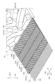
- a rubber crawler 10 according to a first embodiment of the present invention will be described with reference to FIGS.
- An endless rubber crawler 10 as a crawler according to an embodiment of the present invention is a so-called coreless-less type rubber crawler having no cored bar.
- the rubber crawler 10 is used by being wound around a drive wheel 100 connected to a drive shaft of a crawler vehicle as a machine body and an idler wheel 102 rotatably attached to the crawler vehicle.
- a plurality of rolling wheels 104 disposed between the drive wheel 100 and the idler wheel 102 and rotatably attached to the crawler wheel roll on the inner periphery of the rubber crawler 10.
- the circumferential direction of the endless rubber crawler 10 (indicated by an arrow CD in FIG. 2) is described as “crawler circumferential direction”, and the width direction of the rubber crawler 10 (in FIG. 2). (Indicated by an arrow WD) is described as “crawler width direction”.
- the crawler circumferential direction (synonymous with the longitudinal direction of the rubber crawler 10) and the crawler width direction are orthogonal to each other when the rubber crawler 10 is viewed from the inner peripheral side or the outer peripheral side.
- the direction side shown is referred to as “crawler inner peripheral side”
- the outer peripheral side of the rubber crawler 10 and the direction side indicated by the arrow OUT in FIG. 3 is referred to as “crawler outer peripheral side”.
- the arrow IN direction (annular inner direction) and arrow OUT direction (annular outer direction) in FIG. 3 indicate the inner and outer directions of the rubber crawler 10 in the wound state (synonymous with the thickness direction of the rubber crawler 10). .
- the rubber crawler 10 is wound around the driving wheel 100 and the idler wheel 102, but the present invention is not limited to this configuration.
- the rubber crawler 10 may be wound around one or a plurality of the rolling wheels 104 in addition to the driving wheel 100 and the idle wheel 102.
- a crawler traveling device 90 (see FIG. 1) as a traveling unit of the crawler vehicle is configured by the driving wheel 100, the idler wheel 102, the wheel 104, and the rubber crawler 10 wound around these.
- the drive wheel 100 has a pair of disc-shaped wheel portions 100A connected to the drive shaft of the crawler wheel. These wheel portions 100A are configured to roll on the wheel rolling surface 16 with the outer peripheral surface 100B coming into contact with a wheel rolling surface 16 (see FIG. 2) of the crawler body 12 described later.
- the driving wheel 100 causes the driving force from the crawler wheel to act on the rubber crawler 10 (details will be described later) to circulate the rubber crawler 10 between the driving wheel 100 and the idler wheel 102.
- the idler wheel 102 has a pair of disc-shaped wheel portions 102A that are rotatably attached to the crawler wheel. In these wheel portions 102A, the outer peripheral surface 102B comes into contact with the wheel rolling surface 16 and rolls on the wheel rolling surface 16. The idle wheel 102 is moved in a direction away from the drive wheel 100 by a pressure mechanism such as hydraulic pressure (not shown) provided on the crawler vehicle side and is pressed against the wheel rolling surface 16. By pressing the idle wheel 102 against the wheel rolling surface 16 in this way, the tension of the rubber crawler 10 wound around the drive wheel 100 and the idle wheel 102 is maintained.
- a pressure mechanism such as hydraulic pressure (not shown) provided on the crawler vehicle side
- the wheel 104 has a pair of disk-shaped wheel portions 104A that are rotatably attached to the crawler wheel. In these wheel portions 104A, the outer peripheral surface 104B comes into contact with the wheel rolling surface 16 and rolls on the wheel rolling surface 16. The wheel 104 supports the weight of the crawler wheel. The idler wheel 102 and the rolling wheel 104 are driven to rotate with respect to the rubber crawler 10 that circulates between the drive wheel 100 and the idler wheel 102.
- the rubber crawler 10 has a crawler body 12 in which a rubber material as an example of an elastic material is formed in an endless belt shape.
- the crawler body 12 of the present embodiment is an example of an endless belt-like crawler body of the present invention.
- the circumferential direction, the width direction, the inner circumferential side, and the outer circumferential side of the crawler main body 12 of the present embodiment coincide with the crawler circumferential direction, the crawler width direction, the crawler inner circumferential side, and the crawler outer circumferential side, respectively.
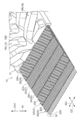
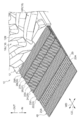
- the crawler main body 12 is formed with a plurality of rubber protrusions 14 protruding from the inner peripheral surface 12A toward the crawler inner peripheral side at intervals in the crawler peripheral direction.
- the rubber protrusion 14 is disposed on a center line CL passing through the center of the crawler body 12 in the crawler width direction. Further, the rubber protrusion 14 is in contact with a wheel rolling on the wheel rolling surface 16 (referring to the driving wheel 100, the idle wheel 102, and the rolling wheel 104), thereby restricting the movement of the wheel in the crawler width direction. .
- Wheel rolling surfaces 16 extending along the crawler circumferential direction are formed on both outer sides in the crawler width direction across the rubber protrusion 14 of the crawler body 12.
- the wheel rolling surface 16 is flat and constitutes a part of the inner peripheral surface 12A of the crawler body 12.
- the crawler main body 12 is provided with a plurality of lugs 18 protruding from the outer peripheral surface 12B to the crawler outer peripheral side.
- the lug 18 extends in the crawler circumferential direction on one side (left side in FIG. 4) and the other side (right side in FIG. 4) across the center line CL of the crawler body 12. They are arranged alternately and distributed to one side and the other side in the crawler width direction.
- the lug 18 on one side in the crawler width direction will be referred to as lug 18L
- the lug 18 on the other side in the crawler width direction will be referred to as lug 18R as appropriate.
- the lug 18 of the present embodiment extends while being inclined with respect to the crawler width direction, but may extend along the crawler width direction.
- the lug 18 is configured to be symmetrical with respect to the center line CL, but is not limited to this configuration.
- the lug 18 may be configured to be asymmetrical with respect to the center line CL.
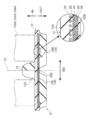
- the crawler main body 12 includes a main code layer 20, a first bias code layer 22, a second bias code layer 24, a third bias code layer 26, a first code, in order from the crawler inner peripheral side.
- a four-bias code layer 28 is embedded.
- the main cord layer 20 has an endless belt shape and includes a main cord 20A extending in the crawler circumferential direction.
- the main cord 20A is configured by twisting a plurality of strands.
- the strand is formed by twisting a plurality of filaments, but the present invention is not limited to this configuration.
- the main cord 20A is covered with rubber.
- a steel cord having excellent tensile strength is used as the main cord 20A.
- the present invention is not limited to this configuration, and the main cord 20A is organic as long as it has sufficient tensile strength. You may use the organic fiber cord comprised with the fiber (for example, aliphatic polyamide fiber, aromatic polyamide fiber, etc.).
- the first bias cord layer 22 has an endless belt shape, and is overlapped on the crawler outer peripheral side of the main cord layer 20.
- the first bias cord layer 22 is formed by arranging a plurality of bias cords 23A extending obliquely with respect to the crawler circumferential direction in a crawler plan view in parallel in the crawler circumferential direction and embedded in a belt-like rubber.
- the second bias code layer 24 has an endless belt shape, and is overlapped on the crawler outer peripheral side of the first bias code layer 22.
- the second bias cord layer 24 extends obliquely with respect to the crawler circumferential direction in a crawler plan view, and a plurality of bias cords 25A intersecting with the bias cord 23A of the first bias cord layer 22 are arranged in parallel in the crawler circumferential direction. At the same time, it is embedded in a rubber band.
- the bias code 25A of the second bias code layer 24 is inclined in the direction opposite to the bias code 23A of the first bias code layer 22 with respect to the crawler circumferential direction.
- the third bias code layer 26 has an endless belt shape and is overlapped on the crawler outer peripheral side of the second bias code layer 24.
- the third bias cord layer 26 is formed by arranging a plurality of bias cords 27A in the crawler circumferential direction and being embedded in a belt-like rubber. Specifically, the bias code 27A of the third bias code layer 26 is inclined in the same direction as the bias code 25A of the second bias code layer 24 with respect to the crawler circumferential direction in a crawler plan view.
- the fourth bias code layer 28 has an endless belt shape and is overlapped on the crawler outer peripheral side of the third bias code layer 26.
- the fourth bias code layer 28 extends obliquely with respect to the crawler circumferential direction in plan view of the crawler, and a plurality of bias cords 29A intersecting with the bias code 27A of the third bias code layer 26 are arranged in parallel in the crawler circumferential direction. It is formed by being embedded in a rubber band.
- the bias code 29A of the fourth bias code layer 28 is inclined in the direction opposite to the bias code 27A of the third bias code layer 26 with respect to the crawler circumferential direction.
- the fourth bias cord layer 28 is the outermost layer on the outer peripheral side of the crawler body 12.
- the bias cord 23A, the bias cord 25A, the bias cord 27A, and the bias cord 29A are the same steel cord.
- the bias cord 23A, the bias cord 25A, the bias cord 27A, and the bias cord 29A are steel cords having a diameter smaller than that of the main cord 20A from the viewpoint of flexibility with respect to the bending of the rubber crawler 10.
- this invention is not limited to this structure, If it has sufficient tensile strength, as the bias cord 23A, the bias cord 25A, the bias cord 27A, and the bias cord 29A, an organic fiber (for example, an aliphatic polyamide fiber, An organic fiber cord composed of aromatic polyamide fiber or the like may be used.
- the first bias code layer 22, the second bias code layer 24, the third bias code layer 26, and the fourth bias code layer 28 are set to have the same width. May be. In the present embodiment, the first bias code layer 22, the second bias code layer 24, the third bias code layer 26, and the fourth bias code layer 28 have the same configuration, but each configuration may be different.
- the bias cord 23A, the bias cord 25A, the bias cord 27A, and the bias cord 29A are steel cords having the same specifications, but the diameter and structure may be different in addition to the material.
- the number of driving (units / cm) per unit width of each of the bias code 23A, the bias code 25A, the bias code 27A, and the bias code 29A is set to be the same, but may be different.
- the inclination angles of the bias code 23A, the bias code 25A, the bias code 27A, and the bias code 29A with respect to the crawler circumferential direction are set to be the same, but may be different. That is, in the present embodiment, the bias code 23A and the bias code 29A are parallel and the bias code 25A and the bias code 27A are parallel when viewed in the crawler thickness direction.
- the bias code 23A and the bias code 29A are parallel and the bias code 25A and the bias code 27A are parallel when viewed in the crawler thickness direction, but the bias code 23A and the bias code 29A are
- the bias cord 25A and the bias cord 27A may not be parallel if they are inclined in the same direction, and may not be completely parallel if they are inclined in the same direction.
- the difference between the inclination angle of one bias cord and the inclination angle of the other bias cord is 30 degrees. The following is preferable.
- the first bias code layer 22, the second bias code layer 24, the third bias code layer 26, and the fourth bias code layer 28 have the same configuration.
- the kind of member which comprises the rubber crawler 10 can be made minimum necessary. In this case, in order to change the inclination direction of the bias code with respect to the crawler circumferential direction, it is only necessary to change the direction of attaching the code layer.
- the main cord 20A is disposed at the center of the crawler main body 12 in the thickness direction (synonymous with the crawler inside / outside direction). Alternatively, they may be arranged shifted to the outer peripheral side.
- the rigidity for example, the bending rigidity in the crawler circumferential direction, the bending rigidity in the crawler width direction, the tensile rigidity in the crawler circumferential direction, the tensile rigidity in the crawler width direction, the torsional rigidity, the shear rigidity in the crawler circumferential direction, and the shear in the crawler width direction Rigidity etc. can be mentioned and according to rubber crawler 10 of this embodiment, one or more of these can be improved.
- a portion of the rubber crawler 10 that is wound around the driving wheel 100 or the idler wheel 102 is a main cord layer 20, a first bias cord layer 22, a second bias cord layer 24, a third bias cord layer 26, and
- the fourth bias cord layer 28 is pulled along the outer circumference of the wheel to cause shear deformation in the crawler width direction, and the outermost outer bias side fourth bias cord layer 28 has the largest shear deformation at the winding portion, The shear deformation decreases in the order of the third bias code layer 26, the second bias code layer 24, and the first bias code layer 22.
- the width of the fourth bias code layer 28 is preferably set within a range of 60% to 100% of the width of the third bias code layer 26 adjacent in the inner circumferential direction. If the width of the fourth bias cord layer 28 is less than 60% of the width of the third bias cord layer 26, the effect of improving the rigidity of the rubber crawler 10 may be insufficient even if the fourth bias cord layer 28 is provided. . On the other hand, when the width of the fourth bias code layer 28 exceeds 100% of the width of the third bias code layer 26, shear deformation of the fourth bias code layer 28 increases, and it is difficult to ensure straight running stability. Become.
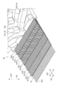
- a rubber crawler 10 according to a second embodiment of the present invention will be described with reference to FIG.
- symbol is attached
- an outer reinforcing cord layer 30 having an endless belt shape is disposed between the main cord layer 20 and the first bias cord layer 22.
- the outer reinforcing cord layer 30 has an endless belt shape, and is overlapped on the crawler outer peripheral side of the main cord layer 20.
- the outer reinforcing cord layer 30 is formed of one reinforcing ply 32 having an endless belt shape.
- the reinforcement ply 32 is formed by embedding a plurality of reinforcement cords 32A extending in the crawler width direction (in other words, a direction orthogonal to the center line CL) in the crawler circumferential direction and embedded in a belt-like rubber.
- “extending along the crawler width direction” herein includes a case where it is inclined about ⁇ 3 degrees with respect to the crawler width direction.
- the inclination directions of the bias code 23A, the bias code 25A, the bias code 27A, and the bias code 29A are set to be opposite to those in the first embodiment.
- the rubber crawler 10 of this embodiment has higher bending rigidity in the crawler width direction than the first rubber crawler 10, and the bending deformation in the crawler width direction is suppressed. Thereby, the durability of the rubber crawler 10 is improved.
- the reinforcing cord 32A of this embodiment uses a steel cord to increase the bending rigidity in the crawler width direction, but the present invention is not limited to this configuration, and may have sufficient bending rigidity in the crawler width direction.
- an organic fiber cord made of organic fibers for example, aliphatic polyamide fiber, aromatic polyamide fiber
- the outer reinforcing cord layer 30 is disposed on the crawler outer peripheral side of the main cord layer 20
- cracks due to trauma on the outer peripheral surface 12B of the crawler body 12 are main cords.
- the traveling speed until reaching the layer 20 can be reduced.
- the malfunction of the main cord 20A due to the ingress of water from the outside can be suppressed over a long period of time, so that the durability of the rubber crawler 10 is improved.
- the outer reinforcing cord layer 30 of the present embodiment is formed by one reinforcing ply 32, but may be formed by two or more reinforcing plies 32.
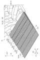
- a rubber crawler 10 according to a third embodiment of the present invention will be described with reference to FIG.
- symbol is attached
- the inner reinforcing cord layer 34 is disposed on the inner peripheral side of the main cord layer 20.
- the inner reinforcing cord layer 34 has an endless belt shape and is overlapped on the inner peripheral side of the crawler of the main cord layer 20.
- the inner reinforcing cord layer 34 is formed by a single endless belt-like reinforcing ply 36 having the same configuration as the reinforcing ply 32 of the second embodiment.
- the rubber crawler 10 of this embodiment has a high bending rigidity in the crawler width direction like the rubber crawler 10 of the second embodiment, and the bending deformation in the crawler width direction is suppressed. Thereby, the durability of the rubber crawler 10 is improved.
- the inner reinforcing cord layer 34 is disposed on the crawler inner peripheral side of the main cord layer 20, which results from trauma on the inner peripheral surface 12 ⁇ / b> A of the crawler body 12.
- the traveling speed until the crack reaches the main cord layer 20 can be reduced.
- the malfunction of the main cord 20A due to the ingress of water from the outside can be suppressed over a long period of time, so that the durability of the rubber crawler 10 is improved.
- the inner reinforcing cord layer 34 of the present embodiment is formed by one reinforcing ply 36, but may be formed by two or more reinforcing plies 32.
- a rubber crawler 10 according to a fourth embodiment of the present invention will be described with reference to FIG.
- symbol is attached
- the four bias code layers of the first bias code layer 22, the second bias code layer 24, the third bias code layer 26, and the fourth bias code layer 28 are provided on the outer peripheral side of the main code layer 20.
- a first additional bias code layer 38 is further added between the main code layer 20 and the first bias code layer 22, and 5 on the outer peripheral side of the main code layer 20. More than one bias code layer may be provided. Thereby, the rigidity of the rubber crawler 10 can be further improved. Even when there are five or more bias code layers, the outermost bias code layer on the outer peripheral side is the fourth bias code layer 28, the inner peripheral side thereof is the third bias code layer 26, and further the inner peripheral side. Is the second bias code layer 24.
- a rubber crawler 10 according to a fifth embodiment of the present invention will be described with reference to FIG.
- symbol is attached
- the second additional bias cord layer 40 is disposed on the inner peripheral side of the main cord layer 20. Accordingly, the bias code 25A of the second additional bias code layer 40 and the bias code 23A of the first bias code layer 22 are inclined in the same direction with respect to the crawler circumferential direction.
- the bias cord 25A of the second additional bias cord layer 40 has a bias of the first bias cord layer 22 with respect to the main cord 20A of the main cord layer 20 that is the bending center of the rubber crawler 10. Since the second additional bias cord layer 40 is twisted to the opposite side to the first bias cord layer 22 when the rubber crawler 10 is bent, the second bias cord layer 22 is twisted when the rubber crawler 10 is bent. Acts to counteract
- the first bias cord layer 22 and the second additional bias cord layer 40 are disposed with the main cord layer 20 interposed therebetween, so that the bias cord from the innermost circumference to the outermost circumference is arranged.
- the thickness of the layer is increased, and the rigidity of the rubber crawler 10 can be increased.
- the outer reinforcing cord layer 30 may be disposed on the outer peripheral side of the main cord layer 20, and the inner reinforcing cord layer 34 may be disposed on the inner peripheral side of the main cord layer 20.
- the outer reinforcing cord layer 30 is not limited to be disposed between the main cord layer 20 and the first bias cord layer 22 but can be disposed between other bias cord layers. However, as in the second embodiment, it is preferably disposed between the main code layer 20 and the first bias code layer 22.
- the rubber crawler 10 does not include a reinforcing metal core on the inner peripheral side of the main cord layer 20, but may include a metal core.
Landscapes
- Engineering & Computer Science (AREA)
- Chemical & Material Sciences (AREA)
- Combustion & Propulsion (AREA)
- Transportation (AREA)
- Mechanical Engineering (AREA)
- Tires In General (AREA)
Abstract
Description
また、メインコード層のクローラ内周側に内側補強コード層が設けられているため、クローラをその内周面側から補強することができる。
また、メインコード層のクローラ外周側に外側補強コード層が設けられているため、クローラをその外周面側から補強することができる。
図1乃至図4にしたがって、本発明の第1の実施形態に係るゴムクローラ10について説明する。本発明の一実施形態に係るクローラとしての無端状のゴムクローラ10は、芯金をもたない、いわゆる芯金レスタイプのゴムクローラである。
なお、上記遊動輪102及び転輪104は、駆動輪100及び遊動輪102の間を循環するゴムクローラ10に対して従動回転するようになっている。
図1及び図2に示されるように、ゴムクローラ10は、弾性材料の一例としてのゴム材を無端帯状に形成したクローラ本体12を有している。なお、本実施形態のクローラ本体12は、本発明の無端帯状のクローラ本体の一例である。また、本実施形態のクローラ本体12の周方向、幅方向、内周側、外周側は、それぞれクローラ周方向、クローラ幅方向、クローラ内周側、クローラ外周側と一致する。
図3及び図4に示されるように、クローラ本体12には、クローラ内周側から順にメインコード層20、第1バイアスコード層22、第2バイアスコード層24、第3バイアスコード層26、第4バイアスコード層28が埋設されている。
本実施形態では、第1バイアスコード層22、第2バイアスコード層24、第3バイアスコード層26、及び第4バイアスコード層28を同じ構成としているが、各々の構成が異なっていても良い。
本実施形態では、バイアスコード23A、バイアスコード25A、バイアスコード27A、及びバイアスコード29Aの各々の単位幅当たりの打ち込み数(本/cm)を同じに設定しているが、異なっていても良い。
次に、本実施形態のゴムクローラ10の作用効果について説明する。
ゴムクローラ10によれば、メインコード層20のクローラ外周側に第1バイアスコード層22、第2バイアスコード層24、第3バイアスコード層26、及び第4バイアスコード層28の4層のバイアスコード層が設けられているため、バイアスコード層が3層設けられたクローラに比較して、剛性を向上させることができる。
剛性としては、例えば、クローラ周方向の曲げ剛性、クローラ幅方向の曲げ剛性、クローラ周方向の引張り剛性、クローラ幅方向の引張り剛性、捻り剛性、クローラ周方向の剪断剛性、及びクローラ幅方向の剪断剛性等を挙げることができ、本実施形態のゴムクローラ10によれば、これらの内の1以上の剛性を向上させることができる。
図5にしたがって、本発明の第2の実施形態に係るゴムクローラ10について説明する。なお、第1の実施形態と同一構成には同一符号を付し、その説明は省略する。
本実施形態のゴムクローラ10では、メインコード層20と第1バイアスコード層22との間に、無端帯状とされた外側補強コード層30が配置されている。
図6にしたがって、本発明の第3の実施形態に係るゴムクローラ10について説明する。なお、第1の実施形態と同一構成には同一符号を付し、その説明は省略する。
本実施形態のゴムクローラ10では、メインコード層20の内周側に内側補強コード層34が配置されている。
図7にしたがって、本発明の第4の実施形態に係るゴムクローラ10について説明する。なお、前述した実施形態と同一構成には同一符号を付し、その説明は省略する。
上記実施形態では、メインコード層20の外周側に第1バイアスコード層22、第2バイアスコード層24、第3バイアスコード層26、及び第4バイアスコード層28の4層のバイアスコード層が設けられていたが、図7に示すように、メインコード層20と第1バイアスコード層22との間に、更に、第1追加バイアスコード層38を追加し、メインコード層20の外周側に5層以上のバイアスコード層を設けるようにしても良い。これにより、ゴムクローラ10の剛性を更に向上することができる。なお、バイアスコード層が5層以上の場合であっても、最外の外周側のバイアスコード層は第4バイアスコード層28とし、その内周側を第3バイアスコード層26、さらに内周側を第2バイアスコード層24とする。
図8にしたがって、本発明の第5の実施形態に係るゴムクローラ10について説明する。なお、前述した実施形態と同一構成には同一符号を付し、その説明は省略する。
図8に示すように、本実施形態のゴムクローラ10では、メインコード層20の内周側に、第2追加バイアスコード層40が配置されている。したがって、第2追加バイアスコード層40のバイアスコード25Aと、第1バイアスコード層22のバイアスコード23Aとは、クローラ周方向に対して互いに同方向に傾斜していることになる。
以上、実施形態を挙げて本発明の実施の形態を説明したが、これらの実施形態は一例であり、要旨を逸脱しない範囲内で種々変更して実施できる。また、本発明の権利範囲がこれらの実施形態に限定されないことは言うまでもない。
外側補強コード層30はメインコード層20と第1バイアスコード層22との間に配置することに限らず、他のバイアスコード層間に配置することもでき、第4バイアスコード層28のクローラ外周側に配置することもできるが、第2の実施形態の様にメインコード層20と第1バイアスコード層22との間に配置することが好ましい。
本明細書に記載されたすべての文献、特許出願、及び技術規格は、個々の文献、特許出願、及び技術規格が参照により取り込まれることが具体的かつ個々に記された場合と同程度に、本明細書中に参照により取り込まれる。
Claims (6)
- 弾性材料によって形成される無端帯状のクローラ本体と、
前記クローラ本体に埋設され、クローラ周方向に対して傾斜して延びる第1バイアスコードがクローラ周方向に並列された第1バイアスコード層と、
前記クローラ本体に埋設され、かつ前記第1バイアスコード層のクローラ外周側に配置され、クローラ周方向に対して前記第1バイアスコードの傾斜方向と反対方向に傾斜して延びる第2バイアスコードがクローラ周方向に並列された第2バイアスコード層と、
前記クローラ本体に埋設され、かつ前記第2バイアスコード層のクローラ外周側に配置され、クローラ周方向に対して前記第2バイアスコードの傾斜方向と同方向に傾斜して延びる第3バイアスコードがクローラ周方向に並列された第3バイアスコード層と、
前記クローラ本体に埋設され、かつ前記第3バイアスコード層のクローラ外周側に配置され、クローラ周方向に対して前記第3バイアスコードの傾斜方向と反対方向に傾斜して延びる第4バイアスコードがクローラ周方向に並列された第4バイアスコード層と、
を有するクローラ。 - 前記第1バイアスコード層のクローラ内周側に、クローラ周方向に沿って延びるメインコードがクローラ幅方向に並列されたメインコード層が配置されている、請求項1に記載のクローラ。
- 前記クローラ本体に埋設され、かつ前記メインコード層のクローラ内周側に配置され、クローラ幅方向に沿って延びる補強コードがクローラ周方向に並列された内側補強コード層を有する、請求項2に記載のクローラ。
- 前記クローラ本体に埋設され、かつ前記メインコード層のクローラ外周側に配置され、クローラ幅方向に沿って延びる補強コードがクローラ周方向に並列された外側補強コード層を有する、請求項2又は請求項3に記載のクローラ。
- 前記第1バイアスコード層のクローラ内周側に、クローラ周方向に対して傾斜して延びる第1追加バイアスコードがクローラ周方向に並列された第1追加バイアスコード層が1層以上設けられている、請求項1~請求項4の何れか1項に記載のクローラ。
- 前記クローラ本体に埋設され、かつ前記メインコード層のクローラ内周側に配置され、クローラ周方向に対して前記第1バイアスコード層の前記第1バイアスコードと同方向に傾斜して延在する第2追加バイアスコードがクローラ周方向に並設された第2追加バイアスコード層が1層以上設けられている、請求項2~請求項4の何れか1項に記載のクローラ。
Priority Applications (3)
| Application Number | Priority Date | Filing Date | Title |
|---|---|---|---|
| CA2988089A CA2988089C (en) | 2015-06-04 | 2016-05-31 | Crawler |
| US15/578,242 US10053169B2 (en) | 2015-06-04 | 2016-05-31 | Crawler |
| CN201680032364.5A CN107614363B (zh) | 2015-06-04 | 2016-05-31 | 履带 |
Applications Claiming Priority (2)
| Application Number | Priority Date | Filing Date | Title |
|---|---|---|---|
| JP2015-114141 | 2015-06-04 | ||
| JP2015114141A JP5813902B1 (ja) | 2015-06-04 | 2015-06-04 | クローラ |
Publications (1)
| Publication Number | Publication Date |
|---|---|
| WO2016194905A1 true WO2016194905A1 (ja) | 2016-12-08 |
Family
ID=54595883
Family Applications (1)
| Application Number | Title | Priority Date | Filing Date |
|---|---|---|---|
| PCT/JP2016/066044 Ceased WO2016194905A1 (ja) | 2015-06-04 | 2016-05-31 | クローラ |
Country Status (5)
| Country | Link |
|---|---|
| US (1) | US10053169B2 (ja) |
| JP (1) | JP5813902B1 (ja) |
| CN (1) | CN107614363B (ja) |
| CA (1) | CA2988089C (ja) |
| WO (1) | WO2016194905A1 (ja) |
Families Citing this family (1)
| Publication number | Priority date | Publication date | Assignee | Title |
|---|---|---|---|---|
| US10875591B2 (en) * | 2015-08-04 | 2020-12-29 | Camso Inc. | Track system for traction of an agricultural vehicle travelling on fields and roads |
Citations (2)
| Publication number | Priority date | Publication date | Assignee | Title |
|---|---|---|---|---|
| US20040235600A1 (en) * | 2002-10-07 | 2004-11-25 | Otico | Endless flexible belt caterpillar track with reinforcing layers, particularly for all-terrain vehicles |
| JP2013166475A (ja) * | 2012-02-15 | 2013-08-29 | Bridgestone Corp | 弾性クローラ |
Family Cites Families (14)
| Publication number | Priority date | Publication date | Assignee | Title |
|---|---|---|---|---|
| US1807133A (en) * | 1923-02-07 | 1931-05-26 | Gordon R Pennington | Belt drive mechanism |
| IT649511A (ja) * | 1960-08-03 | |||
| US4721498A (en) * | 1986-04-14 | 1988-01-26 | Caterpillar Inc. | Endless elastomeric drive belt |
| JP2002178965A (ja) | 2000-12-15 | 2002-06-26 | Bridgestone Corp | ゴムクローラー |
| KR100589650B1 (ko) * | 2004-10-29 | 2006-06-19 | 대륙화학공업 주식회사 | 탈륜방지용 무심금 크로라 |
| JP5026206B2 (ja) * | 2007-09-25 | 2012-09-12 | 株式会社ブリヂストン | ゴムクローラの製造方法及びその成型用金型 |
| JP5264367B2 (ja) * | 2008-08-22 | 2013-08-14 | 株式会社ブリヂストン | ゴムクローラおよびクローラ式走行体 |
| JP5345830B2 (ja) * | 2008-12-04 | 2013-11-20 | 株式会社ブリヂストン | クローラ走行装置 |
| JP5750274B2 (ja) * | 2011-02-15 | 2015-07-15 | 株式会社ブリヂストン | ゴムクローラ |
| JP5851344B2 (ja) | 2012-05-25 | 2016-02-03 | 株式会社ブリヂストン | ゴムクローラ |
| JP2013244846A (ja) * | 2012-05-25 | 2013-12-09 | Bridgestone Corp | ゴムクローラ |
| JP5851545B2 (ja) * | 2014-04-14 | 2016-02-03 | 株式会社ブリヂストン | クローラ |
| JP5851546B2 (ja) * | 2014-04-14 | 2016-02-03 | 株式会社ブリヂストン | クローラ |
| JP2017043204A (ja) * | 2015-08-26 | 2017-03-02 | 株式会社ブリヂストン | クローラ |
-
2015
- 2015-06-04 JP JP2015114141A patent/JP5813902B1/ja not_active Expired - Fee Related
-
2016
- 2016-05-31 WO PCT/JP2016/066044 patent/WO2016194905A1/ja not_active Ceased
- 2016-05-31 CA CA2988089A patent/CA2988089C/en active Active
- 2016-05-31 CN CN201680032364.5A patent/CN107614363B/zh active Active
- 2016-05-31 US US15/578,242 patent/US10053169B2/en active Active
Patent Citations (2)
| Publication number | Priority date | Publication date | Assignee | Title |
|---|---|---|---|---|
| US20040235600A1 (en) * | 2002-10-07 | 2004-11-25 | Otico | Endless flexible belt caterpillar track with reinforcing layers, particularly for all-terrain vehicles |
| JP2013166475A (ja) * | 2012-02-15 | 2013-08-29 | Bridgestone Corp | 弾性クローラ |
Also Published As
| Publication number | Publication date |
|---|---|
| US10053169B2 (en) | 2018-08-21 |
| JP5813902B1 (ja) | 2015-11-17 |
| CA2988089A1 (en) | 2016-12-08 |
| JP2017001414A (ja) | 2017-01-05 |
| US20180148113A1 (en) | 2018-05-31 |
| CN107614363A (zh) | 2018-01-19 |
| CA2988089C (en) | 2019-06-18 |
| CN107614363B (zh) | 2019-12-06 |
Similar Documents
| Publication | Publication Date | Title |
|---|---|---|
| WO2015159896A1 (ja) | クローラ | |
| US9434429B2 (en) | Rubber crawler | |
| CA2988087C (en) | Crawler | |
| JP5851344B2 (ja) | ゴムクローラ | |
| JP2013166475A (ja) | 弾性クローラ | |
| WO2014129659A1 (ja) | クローラ | |
| JP5813902B1 (ja) | クローラ | |
| JP5985261B2 (ja) | 弾性クローラ | |
| JP5869170B1 (ja) | クローラ | |
| JP5901375B2 (ja) | ゴムクローラ | |
| JP2017043204A (ja) | クローラ | |
| JP2016107990A (ja) | クローラ | |
| JP6574116B2 (ja) | 芯金レスクローラ及び芯金レスクローラ装置 | |
| JP5602268B2 (ja) | 弾性クローラ | |
| JP6505042B2 (ja) | クローラ | |
| JP2015202786A (ja) | クローラ |
Legal Events
| Date | Code | Title | Description |
|---|---|---|---|
| 121 | Ep: the epo has been informed by wipo that ep was designated in this application |
Ref document number: 16803339 Country of ref document: EP Kind code of ref document: A1 |
|
| WWE | Wipo information: entry into national phase |
Ref document number: 15578242 Country of ref document: US |
|
| ENP | Entry into the national phase |
Ref document number: 2988089 Country of ref document: CA |
|
| NENP | Non-entry into the national phase |
Ref country code: DE |
|
| 122 | Ep: pct application non-entry in european phase |
Ref document number: 16803339 Country of ref document: EP Kind code of ref document: A1 |