WO2016194854A1 - 表示システム及び表示方法 - Google Patents
表示システム及び表示方法 Download PDFInfo
- Publication number
- WO2016194854A1 WO2016194854A1 PCT/JP2016/065831 JP2016065831W WO2016194854A1 WO 2016194854 A1 WO2016194854 A1 WO 2016194854A1 JP 2016065831 W JP2016065831 W JP 2016065831W WO 2016194854 A1 WO2016194854 A1 WO 2016194854A1
- Authority
- WO
- WIPO (PCT)
- Prior art keywords
- image
- line
- output
- synchronization signal
- signal
- Prior art date
- Legal status (The legal status is an assumption and is not a legal conclusion. Google has not performed a legal analysis and makes no representation as to the accuracy of the status listed.)
- Ceased
Links
Images








Classifications
-
- H—ELECTRICITY
- H04—ELECTRIC COMMUNICATION TECHNIQUE
- H04N—PICTORIAL COMMUNICATION, e.g. TELEVISION
- H04N5/00—Details of television systems
- H04N5/04—Synchronising
- H04N5/05—Synchronising circuits with arrangements for extending range of synchronisation, e.g. by using switching between several time constants
-
- H—ELECTRICITY
- H04—ELECTRIC COMMUNICATION TECHNIQUE
- H04N—PICTORIAL COMMUNICATION, e.g. TELEVISION
- H04N5/00—Details of television systems
- H04N5/04—Synchronising
- H04N5/06—Generation of synchronising signals
- H04N5/067—Arrangements or circuits at the transmitter end
- H04N5/073—Arrangements or circuits at the transmitter end for mutually locking plural sources of synchronising signals, e.g. studios or relay stations
- H04N5/0733—Arrangements or circuits at the transmitter end for mutually locking plural sources of synchronising signals, e.g. studios or relay stations for distributing synchronisation pulses to different TV cameras
-
- H—ELECTRICITY
- H04—ELECTRIC COMMUNICATION TECHNIQUE
- H04N—PICTORIAL COMMUNICATION, e.g. TELEVISION
- H04N5/00—Details of television systems
- H04N5/04—Synchronising
- H04N5/08—Separation of synchronising signals from picture signals
-
- H—ELECTRICITY
- H04—ELECTRIC COMMUNICATION TECHNIQUE
- H04N—PICTORIAL COMMUNICATION, e.g. TELEVISION
- H04N7/00—Television systems
- H04N7/18—Closed-circuit television [CCTV] systems, i.e. systems in which the video signal is not broadcast
- H04N7/181—Closed-circuit television [CCTV] systems, i.e. systems in which the video signal is not broadcast for receiving images from a plurality of remote sources
-
- H—ELECTRICITY
- H04—ELECTRIC COMMUNICATION TECHNIQUE
- H04N—PICTORIAL COMMUNICATION, e.g. TELEVISION
- H04N9/00—Details of colour television systems
- H04N9/44—Colour synchronisation
-
- H—ELECTRICITY
- H04—ELECTRIC COMMUNICATION TECHNIQUE
- H04N—PICTORIAL COMMUNICATION, e.g. TELEVISION
- H04N23/00—Cameras or camera modules comprising electronic image sensors; Control thereof
-
- H—ELECTRICITY
- H04—ELECTRIC COMMUNICATION TECHNIQUE
- H04N—PICTORIAL COMMUNICATION, e.g. TELEVISION
- H04N5/00—Details of television systems
- H04N5/222—Studio circuitry; Studio devices; Studio equipment
- H04N5/262—Studio circuits, e.g. for mixing, switching-over, change of character of image, other special effects ; Cameras specially adapted for the electronic generation of special effects
- H04N5/265—Mixing
Definitions
- the present invention relates to a display system and a display method.
- Patent Literature 1 and Patent Literature 2 There are known display systems in which a plurality of imaging devices such as digital cameras are provided, and images captured by the plurality of imaging devices are combined and displayed (for example, Patent Literature 1 and Patent Literature 2).
- JP 2011-135294 A Japanese Patent Laid-Open No. 10-186550
- the conventional display system synthesizes images after the image synthesizing apparatus completes acquisition of images from a plurality of imaging devices in units of frames, and performs display output in units of frames after the synthesis of the frame images is completed. .
- the imaging start timing by the imaging device it takes a time for at least one frame to complete the output of the frame image by the imaging device. Thereafter, processing time for frame image synthesis occurs.
- the image data is transmitted via a buffer (frame buffer) corresponding to the image in units of frames, and the input / output time of the image data via the buffer is further increased. Arise. These times are delay times from when the image is captured until it is displayed, and the real-time property of the composite image is impaired.
- the delay from when the image is captured until it is displayed The length of time causes a delay in grasping the external situation. For this reason, in the case of such a display system, the delay time is difficult to overlook from the viewpoint of safety.
- the present invention has been made in view of the above-described problems, and further reduces the delay time from when an image is captured by a plurality of imaging devices to when a composite image of the images captured by the plurality of imaging devices is displayed.
- An object of the present invention is to provide a display system and a display method that can be used.
- a display system includes a signal output unit that outputs at least a vertical synchronization signal to a plurality of imaging devices, and a horizontal synchronization signal that is engraved at a predetermined period based on the output timing of the vertical synchronization signal.
- a control unit having a synthesizing unit that synthesizes line-by-line image signals output from each of the plurality of imaging devices at timing, and the line-by-line image signals synthesized by the synthesizing unit sequentially And an image display panel for displaying.
- the display system includes a plurality of imaging devices that output captured images in units of lines, a signal output unit that outputs at least a vertical synchronization signal to the plurality of imaging devices, and the vertical synchronization signal.
- a control unit having a combining unit that combines line-by-line image signals output from each of the plurality of imaging devices at a timing according to a horizontal synchronization signal that is engraved at a predetermined period based on the output timing of And an image display panel for sequentially displaying the image signals in units of lines synthesized by the synthesis unit in units of lines.
- Another embodiment of the present invention is a method for displaying an image by a display device having an image display panel that sequentially displays line-by-line image signals in line units, and outputs at least vertical synchronization signals to a plurality of imaging devices. Based on the output timing of the vertical synchronization signal, the line-by-line image signals output from each of the plurality of imaging devices are synthesized at a timing according to a horizontal synchronization signal that is engraved at a predetermined cycle, and synthesized. The image signal in units of lines is sequentially displayed in units of lines.
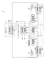
- FIG. 1 is a diagram showing a main configuration of a display system according to Embodiment 1 of the present invention.
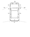
- FIG. 2 is a diagram illustrating an arrangement example of the imaging devices included in the room mirror unit and the side mirror unit.
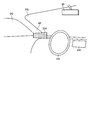
- FIG. 3 is a diagram illustrating an arrangement example of display devices included in the side mirror unit.
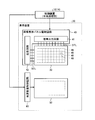
- FIG. 4 is a block diagram illustrating an example of the configuration of the display device.
- FIG. 5 is a diagram illustrating a pixel array of the image display panel according to the first embodiment.
- FIG. 6 is a conceptual diagram of an image display panel and an image display panel drive circuit of the display device according to the first embodiment.
- FIG. 7 is a diagram illustrating another example of the pixel array of the image display panel according to the first embodiment.
- FIG. 1 is a diagram showing a main configuration of a display system according to Embodiment 1 of the present invention.
- FIG. 2 is a diagram illustrating an arrangement example of the imaging devices included in the room mirror unit and the side mirror unit.
- FIG. 8 is a schematic diagram illustrating a relationship between a display unit of the image display panel and a data transfer unit of an image output from the image pickup device included in the three image pickup devices.
- FIG. 9 is a schematic diagram illustrating a relationship between the control device connected to the display device of the room mirror unit according to the first embodiment and the imaging device.
- FIG. 10 is a timing chart showing the relationship between the output timing of the vertical synchronization signal and horizontal synchronization signal according to the first embodiment and the output timing of the line-by-line image signal from the imaging apparatus.
- FIG. 11 is a schematic diagram illustrating a relationship between the control device connected to the display device of the room mirror unit according to the modification and the imaging device.
- FIG. 12 is a timing chart showing the relationship between the output timing of the vertical synchronization signal and the horizontal synchronization signal according to the modification and the output timing of the line-by-line image signal from the imaging apparatus.
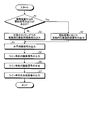
- FIG. 13 is a flowchart illustrating an example of a process flow performed by the control device according to the first embodiment and the modification.
- FIG. 14 is a schematic diagram illustrating a relationship between a control device connected to the display device of the room mirror unit according to the second embodiment and an imaging device.
- FIG. 15 is a schematic diagram illustrating an example of a correspondence relationship between a captured image of the image sensor according to the second embodiment and a composite image displayed on the image display panel.
- FIG. 16 is a schematic diagram illustrating an example of a correspondence relationship between a captured image of the image sensor according to the third embodiment and a composite image displayed on the image display panel.
- FIG. 17 is a timing chart showing the relationship between the output timing of the vertical synchronization signal and horizontal synchronization signal according to the third embodiment and the output timing of the line-by-line image signal from the imaging apparatus.
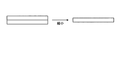
- FIG. 18 is a schematic explanatory diagram illustrating an example of performing reduction in the column direction.
- FIG. 19 is a schematic explanatory diagram illustrating an example of performing enlargement in the column direction.
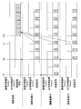
- FIG. 20 is a timing chart illustrating the relationship between the output timing of the vertical synchronization signal and the horizontal synchronization signal according to the fourth embodiment and the output timing of the image signal in units of lines from the imaging apparatus.
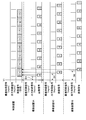
- FIG. 21 is a timing chart illustrating the relationship between the output timing of the vertical synchronization signal and the horizontal synchronization signal and the output timing of the line-by-line image signal from the imaging apparatus in the modified example according to the fourth embodiment.
- FIG. 22 is a timing chart illustrating the relationship between the output timing of the vertical synchronization signal and the horizontal synchronization signal and the output timing of the line-by-line image signal from the imaging apparatus in the modified example according to the fourth embodiment.
- FIG. 1 is a diagram showing a main configuration of a display system 1 according to Embodiment 1 of the present invention.
- the display system 1 includes a room mirror unit 2, two side mirror units 3 ⁇ / b> A and 3 ⁇ / b> B, and a CID (Center Information Display) unit 4.
- the display system 1 is a so-called in-vehicle display system provided in an automobile that is a moving body.
- the room mirror unit 2 and the side mirror units 3A and 3B include an imaging device 5, a display device 20, a control device 10, and the like.
- Each of the room mirror unit 2 and the side mirror units 3A and 3B can function as one processing unit (display system). That is, the rearview mirror unit 2 and the side mirror units 3A and 3B perform image processing of images displayed on the display devices 20, 20A, and 20B included therein by the control devices 10, 10A, and 10B included therein.
- FIG. 2 is a diagram illustrating an arrangement example of the imaging devices 5A, 5B, and 5C included in the room mirror unit 2 and the side mirror units 3A and 3B.
- the angles of view of the imaging devices 5A, 5B, and 5C are indicated by broken lines.
- the room mirror unit 2 and the side mirror units 3A and 3B according to the first embodiment share the imaging device 5.
- the display system 1 according to the first embodiment includes three imaging devices 5A, 5B, and 5C.
- the three imaging devices 5A, 5B, and 5C are arranged behind and to the side of the vehicle body BO of the automobile.
- Three imaging devices 72A, 72B, 72C of the three imaging devices 5A, 5B, 5C are exposed to the outside through a lens 71 (see FIG. 9), and the angle of view is directed outside the vehicle. That is, the three imaging devices 5A, 5B, and 5C capture images that allow confirmation of conditions outside the vehicle. More specifically, the angle of view of the imaging devices 5A and 5B provided on the side and the imaging device 5C provided on the rear are provided so as to be at least continuous, and more preferably, the angles of view partially overlap. It is provided as follows.
- the display device 20 of the room mirror unit 2 displays images captured by the three imaging devices 5A, 5B, and 5C
- the display devices 20A and 20B of the side mirror units 3A and 3B are the rear imaging devices.
- An image obtained by synthesizing an image picked up by 5C and one of the side image pickup devices 5A and 5B is displayed, but this is only an example and is not limited to this, and can be changed as appropriate.
- the imaging devices 5 may be described.
- FIG. 3 is a diagram illustrating an arrangement example of the display device 20A included in the side mirror unit 3A.
- the display device 20A included in the side mirror unit 3A is disposed inside the four-wheeled vehicle and on the side of the driver's seat.
- the display device 20A included in the side mirror unit 3A is provided in the vicinity of the base of the A pillar AP existing between the windshield FG and the side glass SG, for example, as shown in FIG.
- the handle HN and the like are provided at positions opposite to the left and right of the display device 20A included in the side mirror unit 3A with respect to the driver's seat.
- the display devices 20A and 20B included in the side mirror units 3A and 3B display images that mainly indicate the situation on the side of the vehicle body BO in the situation outside the vehicle. That is, the side mirror units 3A and 3B can be used for confirming the situation outside the vehicle, which has been confirmed by a conventional door mirror or fender mirror.
- the display device 20 included in the room mirror unit 2 is provided, for example, near the upper center of the windshield FG, and substitutes for a so-called rearview mirror. That is, the room mirror unit 2 can be used for confirming the situation behind the vehicle, which has been confirmed by a conventional rearview mirror.
- the CID unit 4 includes, for example, a central processing unit 14 and a display device 20C.
- the display device 20C of the CID unit 4 is provided on a dashboard, for example, and functions as a display device for displaying road guidance information and the like in the car navigation system.
- the display device 20C of the CID unit 4 may be provided as a display device that outputs information similar to instruments such as a speedometer, a tachometer, a fuel meter, a water temperature meter, and a distance meter.
- the CID unit 4 is connected to the room mirror unit 2 and the side mirror units 3A and 3B so that data transmission is possible.
- the CID unit 4, the room mirror unit 2, and the side mirror units 3A and 3B are connected through an interface such as HDMI (High-Definition Multimedia Interface), for example.
- HDMI High-Definition Multimedia Interface
- This is an example of a specific form of connection between the CID unit 4, the room mirror unit 2 and the side mirror units 3A and 3B, and is not limited to this, and can be changed as appropriate.
- the display device 20C of the CID unit 4 substitutes the display output of the failed display device when one of the display devices 20, 20A, 20B included in each of the room mirror unit 2 and the side mirror units 3A, 3B fails.
- the central processing unit 14 performs various processes related to display output by the display device 20 ⁇ / b> C of the CID unit 4.
- FIG. 4 is a block diagram illustrating an example of the configuration of the display device 20.
- FIG. 5 is a diagram illustrating a pixel array of the image display panel according to the first embodiment.
- FIG. 6 is a conceptual diagram of an image display panel and an image display panel driving circuit of the display device 20 according to the first embodiment.
- FIG. 7 is a diagram illustrating another example of the pixel array of the image display panel according to the first embodiment.
- the configuration of the display devices 20A and 20B of the side mirror units 3A and 3B and the configuration of the display device 20C of the CID unit 4 according to the first embodiment are also the same as the configuration of the display device 20 shown in FIGS.
- the display device 20 includes an image display panel 30 that displays an image based on an output signal output from the control device 10, and an image display panel drive circuit 40 that controls driving of the image display panel 30.
- the light source device 50 that illuminates the image display panel 30 from, for example, the back surface thereof, and the light source device control circuit 60 that controls the driving of the light source device 50 are provided.
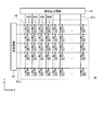
- the image display panel 30 has the pixels 48 arranged in a two-dimensional matrix with P ⁇ Q pixels (P in the row direction and Q in the column direction).
- 5 and 6 show an example in which a plurality of pixels 48 are arranged in a matrix in an XY two-dimensional coordinate system.
- the row direction is the X direction
- the column direction is the Y direction.
- the horizontal synchronization signal is a signal related to scanning in the row direction.
- the vertical synchronization signal is a signal related to scanning in the column direction.
- the pixel 48 includes a first subpixel 49R, a second subpixel 49G, a third subpixel 49B, and a fourth subpixel 49W.
- the first sub-pixel 49R displays a first color component (for example, red as the first primary color).
- the second subpixel 49G displays a second color component (for example, green as the second primary color).
- the third sub-pixel 49B displays a third color component (for example, blue as the third primary color).
- the fourth subpixel 49W displays a fourth color component (specifically, white).
- the first sub-pixel 49R, the second sub-pixel 49G, the third sub-pixel 49B, and the fourth sub-pixel 49W are referred to as sub-pixels 49 when it is not necessary to distinguish them from each other.
- the display device 20 is, for example, a transmissive color liquid crystal display device.
- the image display panel 30 is a color liquid crystal display panel, and a first color filter that passes the first primary color is disposed between the first sub-pixel 49R and the image observer, and the second sub-pixel 49G, the image observer, A second color filter that allows the second primary color to pass therethrough is disposed, and a third color filter that allows the third primary color to pass is disposed between the third sub-pixel 49B and the image observer.
- no color filter is disposed between the fourth sub-pixel 49W and the image observer.
- the fourth subpixel 49W may be provided with a transparent resin layer instead of the color filter. As described above, by providing the transparent resin layer, the image display panel 30 can suppress the occurrence of a large step in the fourth subpixel 49W by not providing the color filter in the fourth subpixel 49W.
- the image display panel 30 includes a first sub-pixel 49R, a second sub-pixel 49G, a third sub-pixel 49B, and a fourth sub-pixel 49W arranged in a predetermined arrangement (for example, a stripe arrangement).
- a predetermined arrangement for example, a stripe arrangement.
- the structure and arrangement of the first subpixel 49R, the second subpixel 49G, the third subpixel 49B, and the fourth subpixel 49W included in one pixel 48 are not particularly limited.
- the first sub-pixel 49R, the second sub-pixel 49G, the third sub-pixel 49B, and the fourth sub-pixel 49W may be arranged in an arrangement similar to a diagonal arrangement (mosaic arrangement).
- the pixel 48A has a first subpixel 49R, a second subpixel 49G, and a third subpixel 49B, and does not have a fourth subpixel 49W. Also good.
- the image display panel drive circuit 40 includes a signal output circuit 41 and a scanning circuit 42.
- the signal output circuit 41 is a so-called source driver, and is an image for driving the pixel 48 in accordance with image data output from the control device 10 (or the central processing unit 14) (line-unit composite image data described later). Generate a signal.
- the image display panel drive circuit 40 holds the video signal by the signal output circuit 41 based on the horizontal synchronization signal and sequentially outputs it to the image display panel 30.
- the signal output circuit 41 is electrically connected to the image display panel 30 through a wiring DTL.
- the pixel 48 operates so that the sub-pixel 49 has a light transmittance corresponding to the video signal.
- the scanning circuit 42 is a so-called gate driver, and outputs a scanning signal corresponding to the pixel row indicated by the image data output from the control device 10 (or the central processing unit 14) based on the vertical synchronization signal.
- the image display panel driving circuit 40 outputs a scanning signal from the scanning circuit 42, whereby a switching element (for example, display brightness, in this case, light transmittance) for controlling the operation of the sub-pixels in the image display panel 30. For example, ON / OFF of a thin film transistor (TFT: Thin Film Transistor) is controlled.
- TFT Thin Film Transistor
- the fact that the scanning circuit 42 turns on / off the switching element via the scanning line SCL means that the switching element can be turned on / off for each pixel row (line) provided along the scanning line SCL. is there.
- the display device 20 is provided so as to be able to control ON / OFF of the display output in units of lines.
- the light source device 50 is disposed on the back surface of the image display panel 30 and irradiates the image display panel 30 with light, thereby functioning as a backlight and illuminating the image display panel 30.
- the light source device 50 may have a front light configuration arranged in front of the image display panel 30.
- the image display panel 30 is a self-luminous display, such as an OLED (Organic Light Emitting Diode) display, or a reflective liquid crystal display that displays external light by reflecting it with a reflective layer (reflective electrode).
- the light source device 50 can be dispensed with.
- the light source device 50 irradiates light on the entire surface of the image display panel 30 to illuminate the image display panel 30.
- the light source device control circuit 60 controls the amount of light emitted from the light source device 50 and the like. Specifically, the light source device control circuit 60 adjusts the duty ratio of the current, voltage, or signal supplied to the light source device 50 based on the light source device control signal output from the control device 10, so that the image display panel 30. The amount of light irradiated (irradiation intensity) is controlled.
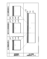
- FIG. 8 is a schematic diagram illustrating a display unit of the image display panel and a data transfer unit of images output from the image pickup devices 72A, 72B, and 72C included in the three image pickup devices 5A, 5B, and 5C.
- the imaging devices 5A, 5B, and 5C are so-called digital cameras that capture images by imaging elements 72A, 72B, and 72C such as a CCD (Charge Coupled Device) image sensor or a CMOS (Complementary Metal Oxide Semiconductor) image sensor.
- the image sensors 72A, 72B, 72C output image signals in line units.
- the image display panel 30 displays an image in line units.
- a line refers to one row (P ⁇ 1) of pixel rows in the image display panel 30. That is, the image sensors 72A, 72B, and 72C sequentially output a plurality of line unit image data constituting one frame of image data as line unit image signals for each row.
- the image display panel 30 displays the line-by-line composite image generated based on the image signals sequentially output in line units from the image pickup devices 72A, 72B, and 72C of the three imaging devices 5A, 5B, and 5C. .
- a combined image in units of lines is an image signal that is sequentially output in units of lines from image sensors (for example, the image sensors 72A, 72B, and 72C) of a plurality of image capture devices (for example, the three image capture devices 5A, 5B, and 5C). It is the image which synthesize
- reference numerals LA1 to LAQ LA are displayed on the line-by-line images output from the imaging elements 72A, 72B, and 72C.
- LB1 to LBQ and LC1 to LCQ are attached.
- reference numerals C1 to CQ are attached to the combined image displayed in units of lines displayed by the image display panel 30.
- the number of pixels in the row direction of the image signals individually output by the image pickup devices 72A, 72B, and 72C included in the three image pickup devices 5A, 5B, and 5C may be the same or different.
- the number of pixels in the row direction when image signals are continued in the row direction is the same. That is, in the first embodiment, the line-by-line image signals output from the image pickup devices 72A, 72B, and 72C of the three image pickup devices 5A, 5B, and 5C are simply connected in the row direction, so that the row direction of the image display panel 30 is reached. A composite image corresponding to the number of pixels is obtained.
- the number of lines of the image sensors 72A, 72B, 72C and the number of lines of the image display panel 30 are the same.
- 1 frame image is composed of multiple line images.
- the image sensors 72A, 72B, and 72C start imaging in accordance with the vertical synchronization signal (vsync), and sequentially output image signals in units of lines in accordance with the clock cycle engraved by the horizontal synchronization signal (hsync).
- vsync vertical synchronization signal
- hsync horizontal synchronization signal
- the display device 20 starts scanning processing related to display according to the vertical synchronization signal, and sequentially displays the combined image in units of lines according to the horizontal synchronization signal.
- the display of all the line-by-line composite images constituting one frame image is completed, the display of the line-by-line composite image constituting the next frame image is started by the vertical synchronization signal output again.
- the time related to the display of all the line-by-line composite images constituting one frame (1F) image may be described as one frame time (1F time).
- the time for displaying a composite image in one line unit may be described as one horizontal synchronization time (1H time).
- the display system according to the first embodiment will be described using the room mirror unit 2 as an example.
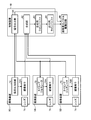
- FIG. 9 is a schematic diagram illustrating a relationship between the control device 10 connected to the display device of the room mirror unit 2 according to the first embodiment and the imaging device 5.
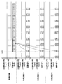
- FIG. 10 is a timing chart illustrating the relationship between the output timing of the vertical synchronization signal and the horizontal synchronization signal according to the first embodiment and the output timing of the line-by-line image signal from the imaging device 5.
- the control device 10 is interposed in the data transmission path between the imaging device 5 and the image display panel drive circuit 40.
- the control device 10 is a circuit that performs various processes related to the operation of the room mirror unit 2.
- the control device 10 includes a signal output unit 81 and a synthesis unit 82.
- the signal output unit 81 outputs a vertical synchronization signal and a horizontal synchronization signal to the plurality of imaging devices 5. Specifically, the signal output unit 81 outputs a vertical synchronization signal and a horizontal synchronization signal to the three imaging devices 5A, 5B, and 5C as shown in FIGS. 9 and 10, for example. More specifically, the signal output unit 81 first outputs a vertical synchronization signal, and sequentially outputs a horizontal synchronization signal at 1H intervals after 1H. Thus, the horizontal synchronization signal is engraved at a predetermined period (1H interval) based on the output timing of the vertical synchronization signal.
- the vertical synchronization signal and the horizontal synchronization signal output from the signal output unit 81 are also output to the image display panel drive circuit 40, and function as a vertical synchronization signal and a horizontal synchronization signal related to display on the image display panel 30, that is, a so-called scan signal.
- the control device 10 may separately output a display control vertical synchronization signal indicating a cycle in which the image display panel 30 starts outputting an image for one frame in the scan process.
- the display control vertical synchronization signal is output at a timing 1H after the output timing of the vertical synchronization signal to the imaging device 5.
- the display control vertical synchronization signal is indicated by a broken line with reference numeral V2.
- the vertical synchronizing signal output to the imaging device 5 is denoted by a solid line with reference numeral V1.
- Each of the three imaging devices 5A, 5B, and 5C sequentially outputs image signals in units of lines with the timing at which the vertical synchronization signal from the control device 10 is input as the start timing. Specifically, the three imaging devices 5A, 5B, and 5C output to the control device 10 line-by-line image signals corresponding to the first lines of the imaging devices 72A, 72B, and 72C using the input timing of the vertical synchronization signal as a trigger. To do. Further, the image signals for the second and subsequent lines of the image pickup devices 72A, 72B, and 72C are sequentially output to the control device 10 in accordance with the input timing of the horizontal synchronization signal that is sequentially input after 1H.
- the output timings of the image signals in units of lines by the three imaging devices 5A, 5B, and 5C are synchronized with the input timings of the vertical synchronization signal and the horizontal synchronization signal from the control device 10.
- a signal for example, an output signal of the timing generator 73
- synchronized with a vertical synchronization signal from the control device 10 after exposure with respect to the image pickup devices arranged in a matrix of the image pickup device 5 Are read out and output as an imaging signal.
- FIG. 10 the relationship between the output timing and the input timing is illustrated with broken-line arrows only for one vertical synchronization signal and horizontal synchronization signal output from the control device 10 to the three imaging devices 5A, 5B, and 5C. The same applies to the vertical synchronizing signal and horizontal synchronizing signal at other timings.
- the imaging device 5 includes a timing generator 73 for operating the imaging unit in accordance with the input timing of the vertical synchronization signal and horizontal synchronization signal from the control device 10.
- the timing generator 73 operates the imaging elements 72A, 72B, and 72C in accordance with the input timings of the vertical synchronization signal and the horizontal synchronization signal from the control device 10, and sets the output cycle of the image signal for each line from the control device 10.
- This is a clock signal generation circuit for matching the input period of the vertical synchronizing signal and horizontal synchronizing signal.
- the synthesizing unit 82 synthesizes the line-by-line image signals output from each of the plurality of imaging devices 5 at a timing according to the vertical synchronization signal and the horizontal synchronization signal.
- the combining unit 82 includes a combining line buffer 83 and an output line buffer 84, for example, as shown in FIG.
- the synthesizing line buffer 83 temporarily stores a synthetic image in line units obtained by synthesizing the line unit image signals output from each of the three imaging devices 5A, 5B, and 5C in a row direction.
- the synthesizer 82 synthesizes the signals output from each of the three imaging devices 5A, 5B, and 5C to generate a line-by-line synthesized image, and stores the synthesized image in the synthesis line buffer 83. Further, the composition unit 82 transfers the composite image in units of lines from the composition line buffer 83 to the output line buffer 84. The output line buffer 84 collectively outputs the transferred line-by-line composite signal to the image display panel drive circuit 40. The combined image in units of lines output from the output line buffer 84 is displayed using each line of the image display panel 30.
- the processing timing by the synthesis unit 82 is synchronized with the output timing of the horizontal synchronization signal. That is, the synthesizing unit 82 synthesizes the line-by-line image signals input in the 1H cycle in synchronization with the horizontal synchronization signal in the 1H cycle to generate a line-by-line synthesized image, and generates the synthesized image from the synthesis line buffer 83 in the 1H cycle.
- the combined image in units of lines is transferred to the output line buffer 84, and the combined signals in units of lines are collectively output from the output line buffer 84 to the image display panel drive circuit 40 in a 1H cycle.
- the correspondence between the line-by-line image signals output from the imaging devices 5 ⁇ / b> A, 5 ⁇ / b> B, and 5 ⁇ / b> C and the line-by-line image signals synthesized by the synthesizing unit 82 is shown in lower case letters.
- the synthesis unit 82 acquires and synthesizes line-by-line image signals at a timing 1 hour after the output timing.
- the relationship between the timing of output and synthesis is indicated by a broken-line arrow only for the image signal to which a small letter B (b) is attached, but the same applies to image signals at other timings.
- the image display panel 30 sequentially displays the line-by-line image signals output from the output line buffer 84 in line units.
- the period in which the image display panel 30 sequentially outputs the line-by-line image signal is synchronized with the horizontal synchronization signal.
- the room mirror unit 2 includes the signal output unit 81 that outputs the vertical synchronization signal and the horizontal synchronization signal to the plurality of imaging devices 5, and the timing of the plurality of imaging devices 5 at the timing according to the vertical synchronization signal and the horizontal synchronization signal.
- the control device 10 includes a combining unit 82 that combines the line-by-line image signals output from each unit, and the image display panel 30 that sequentially displays the line-by-line image signals combined by the combining unit 82 in units of lines. And function as a display system.
- the plurality of imaging devices 5 (for example, the three imaging devices 5A, 5B, and 5C) output captured images in units of lines.
- the vertical synchronization signal output from the signal output unit 81 of the control device 10 determines the start timing of the line-by-line image signal output by the imaging device 5.
- the vertical synchronization signal according to the first embodiment functions as a start signal that instructs the start of the output of the image signal in units of lines.
- the first embodiment has been described using the room mirror unit 2 as an example, but the side mirror units 3A and 3B also operate in the same manner as the room mirror unit 2. That is, the control devices 10A and 10B are the same as the control device 10. That is, the place for displaying images based on a plurality of imaging devices as in the present invention is not limited to the display device 20 of the room mirror unit 2, but may be the display devices 20A and 20B of the side mirror units 3A and 3B.
- the display device 20C of the CID unit 4 may be used.
- the room mirror unit 2 displays images captured by the three imaging devices 5A, 5B, and 5C, while the side mirror units 3A and 3B display images captured by the two imaging devices 5, respectively. indicate.
- the side mirror unit 3A displays images captured by the imaging devices 5A and 5C.
- the side mirror unit 3B displays images captured by the imaging devices 5B and 5C.
- the signal output unit 81 only needs to function as long as the signal output unit 81 included in any one of the control devices 10 of the room mirror unit 2, the side mirror unit 3A, and the side mirror unit 3B functions.
- the signal output unit 81 included in the control device 10 of the room mirror unit 2 functions, and the combining unit 82 and the image display panel 30 of the side mirror unit 3A and the side mirror unit 3B include the signal output unit.
- 81 operates in synchronism with the vertical synchronizing signal and horizontal synchronizing signal output by the terminal 81.
- the one control device 10 when synchronization is performed under the control of the signal output unit 81 included in any one of the control devices 10 of the rearview mirror unit 2, the side mirror unit 3A, and the side mirror unit 3B, the one control device 10 has.
- the vertical synchronization signal and the horizontal synchronization signal from the signal output unit 81 may be output to another control device 10.
- the storage capacity of the composition line buffer 83 and the output line buffer 84 may be a storage capacity that is greater than or equal to the storage capacity necessary for storing the composite image in units of lines. Further, the storage capacity of the composition line buffer 83 and the output line buffer 84 may be smaller than the storage capacity for storing the composite image in units of all lines. Therefore, the storage capacity of these line buffers may be smaller than the storage capacity necessary for storing all display screens (frame images).
- the image sensors 72A, 72B, and 72C of the three imaging devices 5A, 5B, and 5C operate with a vertical synchronization signal and a horizontal synchronization signal that are independent of the vertical synchronization signal and the horizontal synchronization signal output from the control device 10. Yes. That is, the vertical synchronization signal output from the control device 10 is merely used to control the output timing of the image signal in units of lines from the three imaging devices 5A, 5B, and 5C, and the imaging elements 72A, 72B, It is not directly used for the operation control of 72C.
- the phases of the vertical synchronization signal and horizontal synchronization signal of the imaging device 5 and the phases of the vertical synchronization signal and horizontal synchronization signal of the control device 10 may not be synchronized. Specifically, it is only necessary that the output of the image signal in line units from the imaging device 5 catches up with and exceeds the output period of the horizontal synchronizing signal output by the control device 10.
- an image captured by the imaging device 5 can be displayed on the image display panel 30 in line units.
- the time difference between the imaging timing of the image by the imaging device 5 and the display timing of the image by the image display panel 30 can be set to a time in units of lines (for example, 1H time) shorter than 1F time. Therefore, it is possible to further reduce a delay time from when an image is captured by the plurality of imaging devices 5 to when a composite image of the images captured by the plurality of imaging devices 5 is displayed.
- the real-time property in the case of combining and displaying images picked up by the plurality of image pickup devices 5 can be further improved.
- FIG. 11 is a schematic diagram illustrating a relationship between the control device 10 connected to the display device of the room mirror unit 2 according to the modification and the imaging device 5.
- FIG. 12 is a timing chart showing the relationship between the output timing of the vertical synchronization signal and the horizontal synchronization signal and the output timing of the line-by-line image signal from the imaging device 5 according to the modification.
- the signal output unit 81 of the control device 10 according to the modification outputs a vertical synchronization signal and a horizontal synchronization signal according to the start signal output from any of the plurality of imaging devices 5.
- the imaging device 5C outputs a start signal to the control device 10 in synchronization with the output timing of the vertical synchronization signal of the imaging element 72C included in the imaging device 5C.
- the control device 10 is synchronized with the operation of the imaging device 5C based on the start signal. Specifically, as shown in FIG. 12, the signal output unit 81 of the control device 10 outputs a vertical synchronization signal in synchronization with the input timing of the start signal. The signal output unit 81 outputs a horizontal synchronization signal at the same timing as in the first embodiment.
- the imaging device 5C can be synchronized with the operation of the image display panel 30.
- the imaging device 5 ⁇ / b> C includes a signal output circuit 74 for outputting a start signal.
- the period of the vertical synchronization signal and the horizontal synchronization signal of the image sensor 72C included in the imaging device 5C is the same as the period of the vertical synchronization signal and the horizontal synchronization signal output from the signal output unit 81 of the control device 10. It is provided to be a period.
- the imaging device 5C outputs the start signal, but the imaging device 5 that outputs the start signal may be other imaging devices 5A and 5B.
- the control device 10 outputs a vertical synchronization signal and a horizontal synchronization signal to an imaging device (for example, the imaging devices 5A and 5B) other than the imaging device (for example, the imaging device 5C) that has output the start signal.
- the imaging device (for example, the imaging device 5C) that has output the start signal operates based on the vertical synchronization signal and the horizontal synchronization signal that are used for the operation of the imaging device (for example, the imaging device 72C) included in the imaging device.
- An image signal in units of lines is output to the control device 10 in accordance with the output timing of the synchronization signal.
- the operations of the imaging devices (for example, the imaging devices 5A and 5B) other than the imaging device (for example, the imaging device 5C) that output the start signal and the operations of the combining unit 82 of the control device 10 are the same as those in the first embodiment.
- each unit of the display system can be operated based on the operation timing of any of the plurality of imaging devices 5.
- the control device 10 may be provided so as to be changeable by setting whether the configuration for outputting the start signal is the control device 10 or the plurality of imaging devices 5. That is, the control device 10 changes according to the setting whether to operate on the premise that the vertical synchronization signal output from the signal output unit 81 is treated as the start signal or on the premise that the start signal is input from the imaging device 5. May be provided.
- the imaging device 5 may include both the signal output circuit 74 and the timing generator 73 so that the operation of the signal output circuit 74 can be switched on and off. That is, in the case of the first embodiment, the signal output circuits 74 of all the imaging devices 5 are turned off. In the modification, the signal output circuit 74 of any one of the plurality of imaging devices 5 is turned on.
- FIG. 13 is a flowchart illustrating an example of a processing flow by the control device 10 according to the first embodiment and the modification.
- the signal output unit 81 of the control device 10 is passive in accordance with the input timing of the start signal.
- a vertical synchronization signal is output to the other imaging device 5 (step S2).
- the signal output unit 81 of the control device 10 actively sends a vertical synchronization signal to all the imaging devices 5 at an arbitrary timing. Output (step S3).
- the control apparatus 10 outputs a horizontal synchronizing signal with respect to the imaging device 5 which has not output the start signal (step S4).
- an image signal in units of lines is output from each of the plurality of imaging devices 5 to the control device 10 and input to the control device 10 (step S5).
- the synthesizing unit 82 of the control device 10 synthesizes the line-by-line image signals input from each of the plurality of imaging devices 5 (step S6), and outputs them to the image display panel drive circuit 40 (step S7).
- the composite image is displayed on the display panel 30 in units of lines.
- Embodiment 2 Next, Embodiment 2 of the present invention will be described.
- the same components as those of the first embodiment may be denoted by the same reference numerals and the description thereof may be omitted.
- FIG. 14 is a schematic diagram illustrating a relationship between the control device 10 connected to the display device of the room mirror unit 2 according to the second embodiment and the imaging device 5.
- FIG. 15 is a schematic diagram illustrating an example of a correspondence relationship between captured images of the image sensors 72A, 72B, and 72C according to the second embodiment and a composite image displayed on the image display panel 30.
- the control device 10 according to the second embodiment includes image processing units 85A, 85B, and 85C that perform expansion / contraction processing that involves at least one of reduction or enlargement of an image in the row direction. Specifically, for example, as illustrated in FIG.
- the control device 10 has a number of image processing units (for example, three image processing units 85 ⁇ / b> A and 85 ⁇ / b> B) corresponding to the number of the plurality of imaging devices 5 (for example, three). , 85C).
- the plurality of image processing units 85A, 85B, and 85C each process an image in a predetermined row direction with respect to an image in line units obtained from line-by-line image signals output from different imaging devices 5, for example. , Reduce or enlarge.
- the image processing units 85A, 85B, and 85C perform expansion / contraction processing on each line-by-line image signal output from each of the plurality of imaging devices 5 at an individual expansion / contraction rate. Can do.
- the expansion / contraction process for some or all of the lines may be omitted, and a line unit image cut out from the imaging range of the imaging elements 72A, 72B, 72C may be simply output.
- any of the image processing units 85A, 85B, and 85C enlarges the image in the row direction, but any one or more of them may reduce.
- the image signal for each line output from the image sensor 72C of the imaging device 5C is smaller than the number of lines of the image sensor 72C.
- the imaging device 5 may output an image signal for each line so as to extract a part of the captured image in the row direction.
- each imaging device 5 which range of the captured image is extracted.
- the imaging range of the imaging device 5C and the imaging range of the imaging devices 5A and 5B overlap. Therefore, as shown in FIG. 15, among the images captured by the image sensor 72C of the image capture device 5C, the same subject as the images captured by the image sensors 72A and 72B of the image capture devices 5A and 5B is captured due to the overlap of the image capture ranges.
- a common range is extracted for all lines, but an individual range may be extracted for some or all lines in the row direction.
- the range in the line direction that is different for each line is extracted, and the width in the line direction of the frame image is unified after extraction.
- the extraction range and the degree of enlargement or reduction (rate) may be determined so as to eliminate the distortion by enlargement or reduction.
- image processing units 85 ⁇ / b> A, 85 ⁇ / b> B, and 85 ⁇ / b> C are provided in front of the composition line buffer 83.
- the line-by-line image signals output from the image sensors 72A, 72B, and 72C of the three imaging devices 5A, 5B, and 5C and input to the control device 10 are enlarged or reduced through the image processing units 85A, 85B, and 85C. Then, they are synthesized using the synthesis line buffer 83.
- the number of pixels (P) in the row direction of the image display panel 30 and the line-by-line image signals output from the image sensors 72A, 72B, and 72C of the three imaging devices 5A, 5B, and 5C are continuously provided in the row direction.
- the number of pixels in the row direction may not be the same.
- a resampling method (resampling) associated with enlargement or reduction is arbitrary, and any or a plurality of methods that can be employed for resampling an image composed of a plurality of pixels at present or in the future. Good.
- an image can be displayed in line units after performing an expansion / contraction process involving at least one of reduction or enlargement of an image in the row direction.
- the image processing units 85A, 85B, and 85C perform enlargement or reduction only in the row direction and do not involve image processing in the column direction. For this reason, it is not necessary to hold a frame image necessary for enlarging or reducing in the column direction. Therefore, the control device 10 can perform image processing in units of lines without causing a waiting time for completing a frame image before processing.
- FIG. 16 is a schematic diagram illustrating an example of a correspondence relationship between captured images of the image sensors 72A, 72B, and 72C according to the third embodiment and a composite image displayed on the image display panel 30.
- FIG. 17 is a timing chart showing the relationship between the output timing of the vertical synchronization signal and the horizontal synchronization signal according to the third embodiment and the output timing of the line-by-line image signal from the imaging device 5.
- the signal output unit 81 of the control device 10 according to the third embodiment outputs the output timing of the vertical synchronization signal to the imaging device 5 and the display control vertical synchronization signal used for display control of the image display panel 30 at different timings.
- the combining unit 82 of the control device 10 includes line unit image signals that are output from the image pickup devices 72A, 72B, and 72C included in the image pickup device 5 according to the timing of the vertical synchronization signal.
- the line-by-line image signal corresponding to the output timing of the display control vertical synchronization signal is synthesized as the line-by-line image signal output on the first display line of the image display panel 30.
- the control device 10 outputs the output timing of the vertical synchronization signal to the imaging device 5 and the display control vertical synchronization signal used for display control of the image display panel 30 at different timings. .
- an image from the fifth line of the imaging device 72C of the imaging device 5C and an image from the third line of the imaging devices 72A and 72B of the imaging devices 5A and 5B are displayed on the first line ( In the case of compositing so as to obtain an image of the first line), as shown in FIG. 17, first, the vertical synchronization signal V3 for the imaging device 5C is output, and the timing when two horizontal synchronization signal times (2H time) have elapsed. The vertical synchronization signal V4 for the imaging devices 5A and 5B is output. Further, the display control vertical synchronizing signal V2 is output in accordance with the display start timing.
- the control device 10 outputs the image signal of the fifth line output from the imaging element 72C of the imaging device 5C and acquired at the timing at the timing of the horizontal synchronization signal immediately before the timing, the imaging devices 5A,
- the image signal of the third line output from the 5B imaging elements 72A and 72B can be acquired as an image signal that is the basis of the composite image when the first line of the image display panel 30 is driven.
- the specific range of the image range described with reference to FIG. 16 and the timing described with reference to FIG. 17 is merely an example, and is not limited to this, and is arbitrary according to the range of the image to be displayed. Can be changed.
- the number of lines of the image pickup devices 72A, 72B, and 72C is larger than the number of lines of the image display panel 30.
- the number of lines constituting a partial line unit image to be displayed on the image display panel 30 among all the line unit images captured by the imaging elements 72A, 72B, and 72C is as follows. It is desirable that the number of lines is the same as that of the image display panel 30. When such a condition is satisfied, a part of the line unit image can be obtained by simply synthesizing the line unit images of the image sensors 72A, 72B, 72C obtained at the timing of the horizontal synchronization signal related to the scan processing of the image display panel 30. It can be displayed on the display panel 30.
- the end side such as the surplus range T shown in FIG.
- the line image can be easily cut off.
- FIG. 16 in addition to the extraction of a part of the line unit image, the expansion in the row direction described in the second embodiment is performed at the same time.
- the image processing according to the second embodiment and the composite image generation method according to the third embodiment can be performed simultaneously.
- a modification can also be applied to Embodiment 2, Embodiment 3, or Embodiment which concerns on the combination of Embodiment 2 and Embodiment 3.
- FIG. 18 is a schematic explanatory diagram illustrating an example of performing reduction in the column direction.
- FIG. 19 is a schematic explanatory diagram illustrating an example of performing enlargement in the column direction. More specifically, the configuration of the control device 10 (for example, the image processing units 85A, 85B, and 85C) is one line after receiving a plurality of lines from the imaging device 5, as shown in FIG. It is also possible to perform a process of combining and outputting. In the case of enlargement, for example, as shown in FIG. 19, the configuration may perform a process of outputting to a plurality of lines after receiving one line from the imaging device 5. By these processes, the line can be enlarged / reduced by a constant multiple in the column direction. 18 and 19 exemplify reduction / enlargement of 1: 2 lines, but the ratio of the number of lines before and after processing in enlargement / reduction is arbitrary.
- the extraction range of the captured image, the degree of enlargement or reduction by the image processing units 85A, 85B, and 85C, and the like in the second and third embodiments may be provided so as to be switched depending on the situation.
- the degree of enlargement or reduction (number or ratio of lines to be enlarged or reduced) or the like may be changed according to the moving direction / moving speed of the moving body.
- the extraction range of the captured image and the degree of enlargement or reduction by the image processing units 85A, 85B, and 85C may be switched between when the automobile is moving forward and when the vehicle is moving backward. Further, the degree of enlargement or reduction may be switched according to the moving speed of the automobile.
- the setting of the degree of enlargement or reduction by the image processing units 85A, 85B, 85C can be dealt with, for example, when the control device 10 has a record holding unit 86 (see FIG. 14) for the setting in the circuit. .
- the extraction range of the captured image can be dealt with by providing a control circuit 75 (see FIG. 14) for controlling the extraction range for each imaging device 5, for example.
- a circuit provided individually for each imaging device 5 such as the control circuit 75 is used, and only a part of line-unit image signals individually set for each of the imaging elements 72A, 72B, 72C are limited to be output. May be. That is, the output target line may be limited at the stage where the image signal is output from the imaging device 5. In this case, output similar to the example shown in FIG. 16 can be performed by omitting the timing control as shown in FIG.
- the shortest delay time DA is a time corresponding to the time between the vertical synchronizing signal and the horizontal synchronizing signal corresponding to the first line.
- the second shortest delay time DC is a time obtained by adding the time spent for the output of the first line-unit image signal by the image pickup device 72A of the image pickup apparatus 5A and the delay time DA.
- the longest delay time DB is the time spent for outputting the first line-unit image signal that is sequentially performed by the imaging elements 72A and 72C of the imaging device 5 (imaging devices 5A and 5C) other than the imaging device 5B. And the total delay time and the delay time DA are added together.
- the plurality of imaging devices 5 start outputting line-by-line image signals at timings that have passed through different delay times DA, DB, and DC with respect to the output timing of the vertical synchronization signal. That is, in the example shown in FIG. 20, the output timing of the line-by-line image signal output from each of the three imaging devices 5A, 5B, and 5C is the row direction in the image display panel 30 with respect to the output timing of the vertical synchronization signal. Is a timing after passing through different delay times DA, DB, and DC depending on the display position.
- the image pickup devices 72A, 72B, and 72C included in each of the timings output image signals in units of lines at such timing, so that the control device 10 displays the image signals in units of lines that are sequentially input as shown in FIG. Scanning (horizontal scanning) along the line direction in the image display panel 30 can be performed only by sequentially outputting to the drive circuit 40. That is, in the fourth embodiment, the arrangement order of the line-by-line image signals sequentially input from the imaging elements 72A, 72B, 72C included in the three imaging devices 5A, 5B, 5C to the control device 10 is the line in the image display panel 30 as it is. This corresponds to the order of display output contents (gradation values) along the direction.
- the output start timing of the horizontal synchronization signal used for the scan process of the image display panel 30 is not limited to 1H hours after the output timing of the vertical synchronization signal, and may be less than 1H time. Specifically, the time between the output timing of the vertical synchronization signal and the output timing of the horizontal synchronization signal used for the scanning process can be shortened to the shortest delay time (for example, delay time DA).
- the image signal from the imaging device 5A and the image signal from the imaging device 5C are based on the arrangement of the three imaging devices 5A, 5B, and 5C and the scanning order in the row direction on the image display panel 30.
- the delay times DA, DB, and DC are set so that the line-by-line image signals are output in the order of the image signals from the imaging device 5B, but the line-by-line image signal connection order for generating the composite image is set. Is optional.
- the output of image signals in units of lines is performed based on the horizontal synchronization signal carved by each of the imaging devices 5A, 5B, and 5C according to the delay times DA, DB, and DC from the first vertical synchronization signal V1.
- 21 and 22 are timing charts showing the relationship between the output timing of the vertical synchronization signal and the horizontal synchronization signal and the output timing of the line-by-line image signal from the imaging device 5 in the modification according to the fourth embodiment.
- the control device 10 outputs a horizontal synchronization signal as in the first embodiment, and applies different delay times to the timing of the horizontal synchronization signal.
- each of the imaging devices 5A, 5B, 5C may output an image signal in units of lines.
- the control device 10 outputs a horizontal synchronization signal in which individual delay times are applied to the imaging devices 5A, 5B, and 5C.
- each of the imaging devices 5A, 5B, and 5C may output an image signal in units of lines.
- the correct pixels in the image display panel 30 can be obtained simply by sequentially transferring image signals in line units that are sequentially input from the three imaging devices 5A, 5B, and 5C to the control device 10 to the image display panel drive circuit 40. Therefore, a line buffer for generating a composite image becomes unnecessary. For this reason, it is possible to complete the process from imaging to display without causing time for data transfer via the line buffers (combining line buffer 83, output line buffer 84) in the first embodiment. Therefore, in addition to the need for a line buffer, the delay time from when an image is captured by the plurality of imaging devices 5 to when a composite image of the images captured by the plurality of imaging devices 5 is displayed is further reduced. be able to. Moreover, the real-time property in the case of combining and displaying images picked up by the plurality of image pickup devices 5 can be further improved.
- the number of pixels in the row direction when the unit image signal is continued in the row direction is the same.
- the number of lines of the image sensors 72A, 72B, 72C and the number of lines of the image display panel 30 are the same (see FIG. 8).
- the delay time is individually set in advance in the timing generator 73, for example. That is, in the case of the example shown in FIG. 20, according to the timing of the vertical synchronization signal, the three imaging devices 5A, 5B, and 5C have the first line unit image signal at the timing corresponding to the individual delay times DA, DB, and DC. Automatically start output.
- the phase of the horizontal synchronization signal of each imaging device 5 and the phase of the horizontal synchronization signal related to display driving of the image display panel 30 are synchronized. In order to realize such synchronization, in the fourth embodiment, for example, phase synchronization between devices using a phase synchronization circuit (PLL: Phase Locked Loop) or the like is performed.
- PLL Phase Locked Loop
- a liquid crystal display device has been exemplified as a disclosure example of the display device 20, but as other application examples, an organic electroluminescence (EL) display device, All flat panel display devices such as other self-luminous display devices can be mentioned. Moreover, it cannot be overemphasized that it can apply, without specifically limiting from a small size to a large size.
- EL organic electroluminescence
- the number of imaging devices may be two or more.
- the combining unit may combine two or more captured output contents and output them to the display unit.
- the automobile may include only some of the room mirror unit 2, the side mirror units 3A and 3B, and the CID unit 4. Further, a part of the devices constituting each unit may be integrated into one unit. For example, there may be one or more display devices as the configuration of the display system. Further, in the present invention, the composite display is performed by the display device of the room mirror unit 2, but the position of the display device that performs the composite display is not limited to this, and the composite display is performed by the side mirror units 3A and 3B or the CID unit 4. May be implemented.
- the line indicates the pixel row for one line.
- the present invention is not limited to this, and there are cases where the line has a plurality of lines (a number smaller than all the lines). May be included. More specifically, output for a plurality of rows may be received from the imaging elements of a plurality of imaging devices, and composite display may be performed for each row.
- the case of an automobile is illustrated as an example of disclosure of a moving body, but a body in which three or more wheels and an occupant can sit on a seat provided in the passenger compartment.
- the present invention is not limited to a so-called automobile equipped with the above-mentioned, but can be applied to any two-wheeled vehicle provided with a so-called body, and can also be applied to other moving bodies such as a motor boat.
- control device 10 and the display device 20 are independent, but the control device 10 may have a configuration that the display device 20 has.
- the circuit having the same function as that of the control device 10 may be one of the circuits constituting the display device 20.
- a part of the configuration for example, a line buffer (combination line buffer 83, output line buffer 84) may be formed on the substrate of the image display panel 30 of the display device 20.
- the control device 10 according to the present invention may be formed in a display driver IC or may be realized by an external control circuit such as an MCU (Memory Control Unit). In the case of a driver IC, it may be arranged on the same substrate as the display panel by COG (Chip On Glass) or the like, or may be arranged on another substrate.
- COG Chip On Glass
- signal transmission among the devices included in the imaging device, the control device, and the display device may be wired or wireless.
- the configurations corresponding to the imaging device 5, the control device 10, and the display device 20 may be arranged in different devices (terminals or the like).
- an output signal for each line by an imaging device attached to a remotely operable mobile body is transmitted by wireless communication to a control device disposed in a mobile terminal different from the mobile body, the terminal, Or it is also possible to display on a display device arranged in a different terminal.
Landscapes
- Engineering & Computer Science (AREA)
- Multimedia (AREA)
- Signal Processing (AREA)
- Control Of Indicators Other Than Cathode Ray Tubes (AREA)
- Controls And Circuits For Display Device (AREA)
- Closed-Circuit Television Systems (AREA)
- Studio Devices (AREA)
Abstract
表示システムは、少なくとも垂直同期信号を複数の撮像装置に出力する信号出力部と、垂直同期信号の出力タイミングに基づいて所定の周期で刻まれる水平同期信号に応じたタイミングで複数の撮像装置の各々から出力されたライン単位の画像信号をライン単位で合成する合成部とを有する制御装置と、合成部により合成されたライン単位の画像信号をライン単位で逐次表示する画像表示パネルと、を有する。
Description
本発明は、表示システム及び表示方法に関する。
デジタルカメラ等の撮像装置を複数設け、係る複数の撮像装置により撮像された画像を合成して表示出力する表示システムが知られている(例えば特許文献1、特許文献2)。
しかしながら、従来の表示システムは、画像を合成する装置が複数の撮像装置からフレーム単位で画像の取得を完了した後に画像を合成し、係るフレーム画像の合成が完了した後にフレーム単位で表示出力を行う。このため、撮像装置による撮像開始タイミングを基準として、撮像装置によるフレーム画像の出力完了に最低1フレーム分の時間がかかる。その後、フレーム画像の合成のための処理時間が生じる。さらに、フレーム単位で画像を合成及び表示するため、フレーム単位の画像に応じたバッファ(フレームバッファ)を経由して画像データを伝送することになり、バッファを経由した画像データの入出力時間がさらに生じる。これらの時間は、画像が撮像されてから表示されるまでの遅延時間となり、合成画像のリアルタイム性を損なっていた。
特に、自動車等の移動体に搭載され、移動体の外部の状況を複数の撮像装置でモニターするための画像を表示するような表示システムの場合、画像が撮像されてから表示されるまでの遅延時間の長大さは、外部の状況の把握の遅れをもたらす。このため、係る表示システムの場合、当該遅延時間は、安全性の面から看過し難い。
本発明は、上記の課題に鑑みてなされたもので、複数の撮像装置により画像が撮像されてから当該複数の撮像装置により撮像された画像の合成画像が表示されるまでの遅延時間をより低減することができる表示システム及び表示方法を提供することを目的とする。又は、複数の撮像装置により撮像された画像を合成して表示する場合におけるリアルタイム性をより向上させることができる表示システム及び表示方法を提供することを目的とする。
本発明の一態様である表示システムは、少なくとも垂直同期信号を複数の撮像装置に出力する信号出力部と、前記垂直同期信号の出力タイミングに基づいて所定の周期で刻まれる水平同期信号に応じたタイミングで前記複数の撮像装置の各々から出力されたライン単位の画像信号をライン単位で合成する合成部とを有する制御装置と、前記合成部により合成されたライン単位の画像信号をライン単位で逐次表示する画像表示パネルと、を有する。
また、本発明の一態様である表示システムは、撮像した画像をライン単位で出力する複数の撮像装置と、少なくとも垂直同期信号を前記複数の撮像装置に出力する信号出力部と、前記垂直同期信号の出力タイミングに基づいて所定の周期で刻まれる水平同期信号に応じたタイミングで前記複数の撮像装置の各々から出力されたライン単位の画像信号をライン単位で合成する合成部とを有する制御装置と、前記合成部により合成されたライン単位の画像信号をライン単位で逐次表示する画像表示パネルと、を有する。
また、本発明の一態様は、ライン単位の画像信号をライン単位で逐次表示する画像表示パネルを有する表示装置による画像の表示方法であって、少なくとも垂直同期信号を複数の撮像装置に出力し、前記垂直同期信号の出力タイミングに基づいて所定の周期で刻まれる水平同期信号に応じたタイミングで前記複数の撮像装置の各々から出力されたライン単位の画像信号をライン単位で合成し、合成されたライン単位の画像信号をライン単位で逐次表示する。
以下に、本発明の各実施形態について、図面を参照しつつ説明する。なお、開示はあくまで一例にすぎず、当業者において、発明の主旨を保っての適宜変更について容易に想到し得るものについては、当然に本発明の範囲に含有されるものである。また、図面は説明をより明確にするため、実際の態様に比べ、各部の幅、厚さ、形状等について模式的に表される場合があるが、あくまで一例であって、本発明の解釈を限定するものではない。また、本明細書と各図において、既出の図に関して前述したものと同様の要素には、同一の符号を付して、詳細な説明を適宜省略することがある。
(実施形態1)
図1は、本発明の実施形態1による表示システム1の主要構成を示す図である。図1に示すように、表示システム1は、ルームミラーユニット2、2つのサイドミラーユニット3A,3B及びCID(Center Information Display)ユニット4を備える。表示システム1は、移動体である自動車に設けられたいわゆる車載の表示システムである。
図1は、本発明の実施形態1による表示システム1の主要構成を示す図である。図1に示すように、表示システム1は、ルームミラーユニット2、2つのサイドミラーユニット3A,3B及びCID(Center Information Display)ユニット4を備える。表示システム1は、移動体である自動車に設けられたいわゆる車載の表示システムである。
ルームミラーユニット2及びサイドミラーユニット3A,3Bは、撮像装置5、表示装置20、制御装置10等を有する。ルームミラーユニット2及びサイドミラーユニット3A,3Bは、それぞれが1つの処理単位(表示システム)として機能しうる。すなわち、ルームミラーユニット2及びサイドミラーユニット3A,3Bは、それぞれが有する表示装置20,20A,20Bに表示される画像の画像処理を、それぞれが有する制御装置10,10A,10Bにより行う。
図2は、ルームミラーユニット2及びサイドミラーユニット3A,3Bが有する撮像装置5A,5B,5Cの配置例を示す図である。図2では、撮像装置5A,5B,5Cの画角を破線で示している。実施形態1に係るルームミラーユニット2及びサイドミラーユニット3A,3Bは、撮像装置5を共有する。具体的には、例えば図2に示すように、実施形態1に係る表示システム1は、3つの撮像装置5A,5B,5Cを有する。3つの撮像装置5A,5B,5Cは、自動車の車体BOの後方及び側方に配置される。3つの撮像装置5A,5B,5Cの3つの撮像素子72A,72B,72Cはレンズ71(図9参照)を介して外部に露出しており、画角が車外に向けられている。すなわち、3つの撮像装置5A,5B,5Cは、車外の状況を確認可能な画像を撮像する。より具体的には、側方に設けられる撮像装置5A,5Bと後方に設けられる撮像装置5Cの画角とは、少なくとも連続するように設けられ、より好適には、画角が一部重複するように設けられている。これにより、側方の撮像装置5A,5Bの画角のうち、自動車の前方側の画角AV1,AV2よりも後方の状況を3つの撮像装置5A,5B,5Cの撮像範囲内に収めることができる。実施形態1では、例えばルームミラーユニット2の表示装置20が3つの撮像装置5A,5B,5Cにより撮像された画像を表示し、サイドミラーユニット3A,3Bの表示装置20A,20Bが後方の撮像装置5Cと側方の撮像装置5A,5Bのうち1つにより撮像された画像を合成した画像を表示するが、これは一例であってこれに限られるものでなく、適宜変更可能である。撮像装置5A,5B,5Cを特に区別する必要がない場合、撮像装置5と記載することがある。
図3は、サイドミラーユニット3Aが有する表示装置20Aの配置例を示す図である。サイドミラーユニット3Aが有する表示装置20Aは、四輪自動車の車内であって運転席の側方に配置される。具体的には、サイドミラーユニット3Aが有する表示装置20Aは、例えば図3に示すように、フロントガラスFGとサイドガラスSGとの間に存するAピラーAPの付け根付近に設けられる。サイドミラーユニット3Bが有する表示装置20Bは、ハンドルHN等が運転席に対してサイドミラーユニット3Aが有する表示装置20Aと左右逆の位置に設けられる。サイドミラーユニット3A,3Bが有する表示装置20A,20Bは、車外の状況のうち主に車体BOの側方の状況を示す画像を表示する。すなわち、サイドミラーユニット3A,3Bは、従来ドアミラー又はフェンダーミラーにより確認されていた車外側方の状況確認に利用することができる。ルームミラーユニット2が有する表示装置20は、例えばフロントガラスFGの中央上部付近に位置するよう設けられ、いわゆるバックミラーを代替する。すなわち、ルームミラーユニット2は、従来バックミラーにより確認されていた車外後方の状況確認に利用することができる。
CIDユニット4は、例えば中央処理部14、表示装置20C等を備える。CIDユニット4の表示装置20Cは、例えばダッシュボードに設けられて、カーナビゲーションシステムにおける道案内情報等を表示するための表示装置として機能する。CIDユニット4の表示装置20Cは、スピードメータ、タコメータ、燃料計、水温計、距離計等の計器類と同様の情報を出力する表示装置として設けられてもよい。
実施形態1に係るCIDユニット4は、ルームミラーユニット2及びサイドミラーユニット3A,3Bとデータ伝送可能に接続される。具体的には、CIDユニット4とルームミラーユニット2及びサイドミラーユニット3A,3Bとは例えばHDMI(登録商標)(High-Definition Multimedia Interface)等のインタフェースを介して接続されるが、係る接続形態は、CIDユニット4とルームミラーユニット2及びサイドミラーユニット3A,3Bとの接続の具体的形態の一例であってこれに限られるものでなく、適宜変更可能である。CIDユニット4の表示装置20Cは、ルームミラーユニット2及びサイドミラーユニット3A,3Bの各々が有する表示装置20,20A,20Bのうちいずれかが故障した場合、故障した表示装置の表示出力を代替する。中央処理部14は、CIDユニット4の表示装置20Cによる表示出力に係る各種の処理を行う。
図4は、表示装置20の構成の一例を示すブロック図である。図5は、実施形態1に係る画像表示パネルの画素配列を示す図である。図6は、実施形態1に係る表示装置20の画像表示パネル及び画像表示パネル駆動回路の概念図である。図7は、実施形態1に係る画像表示パネルの画素配列の他の例を示す図である。サイドミラーユニット3A,3Bの表示装置20A,20Bの構成及び実施形態1に係るCIDユニット4の表示装置20Cの構成も、図4乃至図7に示す表示装置20の構成と同様である。
図4に示すように、表示装置20は、制御装置10から出力された出力信号に基づいて画像を表示させる画像表示パネル30と、画像表示パネル30の駆動を制御する画像表示パネル駆動回路40と、画像表示パネル30を、例えばその背面から照明する光源装置50と、光源装置50の駆動を制御する光源装置制御回路60と、を備える。
図5、図6に示すように、画像表示パネル30は、画素48が、P×Q個(行方向にP個、列方向にQ個)、2次元のマトリクス状に配列されている。図5、図6に示す例は、XYの2次元座標系に複数の画素48がマトリクス状に配列されている例を示している。この例において、行方向がX方向、列方向がY方向である。また、水平同期信号は、行方向の走査に係る信号である。また、垂直同期信号は、列方向の走査に係る信号である。
画素48は、第1副画素49Rと、第2副画素49Gと、第3副画素49Bと、第4副画素49Wとを有する。第1副画素49Rは、第1色成分(例えば、第1原色として赤色)を表示する。第2副画素49Gは、第2色成分(例えば、第2原色として緑色)を表示する。第3副画素49Bは、第3色成分(例えば、第3原色として青色)を表示する。第4副画素49Wは、第4色成分(具体的には白色)を表示する。以下において、第1副画素49Rと、第2副画素49Gと、第3副画素49Bと、第4副画素49Wとをそれぞれ区別する必要がない場合、副画素49という。
表示装置20は、より具体的には、例えば透過型のカラー液晶表示装置である。画像表示パネル30は、カラー液晶表示パネルであり、第1副画素49Rと画像観察者との間に第1原色を通過させる第1カラーフィルタが配置され、第2副画素49Gと画像観察者との間に第2原色を通過させる第2カラーフィルタが配置され、第3副画素49Bと画像観察者との間に第3原色を通過させる第3カラーフィルタが配置されている。また、画像表示パネル30は、第4副画素49Wと画像観察者との間にカラーフィルタが配置されていない。第4副画素49Wには、カラーフィルタの代わりに透明な樹脂層が備えられていてもよい。このように画像表示パネル30は、透明な樹脂層を設けることで、第4副画素49Wにカラーフィルタを設けないことによって第4副画素49Wに大きな段差が生じることを抑制することができる。
そして、画像表示パネル30は、図5に示す例では、第1副画素49R、第2副画素49G、第3副画素49B及び第4副画素49Wが所定の配列(例えばストライプ配列)で配置されている。なお、1つの画素48に含まれる第1副画素49R、第2副画素49G、第3副画素49B、第4副画素49Wの構造及びその配置は特に限定されない。例えば、画像表示パネル30は、第1副画素49R、第2副画素49G、第3副画素49B及び第4副画素49Wをダイアゴナル配列(モザイク配列)に類似した配列で配置してもよい。また、例えば、デルタ配列(トライアングル配列)に類似した配列、レクタングル配列に類似した配列等としてもよい。さらに、図7に示す画像表示パネル30Aのように、画素48Aが第1副画素49R、第2副画素49G及び第3副画素49Bを有し、第4副画素49Wを有しない構成であってもよい。
画像表示パネル駆動回路40は、信号出力回路41及び走査回路42を備えている。信号出力回路41は、所謂ソースドライバであり、制御装置10(又は中央処理部14)から出力された画像データ(後述するライン単位の合成画像のデータ)に応じて画素48を駆動するための映像信号を生成する。画像表示パネル駆動回路40は、水平同期信号に基づいて、信号出力回路41によって映像信号を保持し、順次、画像表示パネル30に出力する。信号出力回路41は、配線DTLによって画像表示パネル30と電気的に接続されている。画素48は、副画素49が映像信号に応じた光透過率となるように動作する。走査回路42は、所謂ゲートドライバであり、垂直同期信号に基づいて、制御装置10(又は中央処理部14)から出力された画像データが示す画素行に応じた走査信号を出力する。画像表示パネル駆動回路40は、走査回路42が走査信号を出力することによって、画像表示パネル30における副画素の動作(例えば表示輝度で、この場合は光透過率)を制御するためのスイッチング素子(例えば、薄膜トランジスタ(TFT:Thin Film Transistor))のON/OFFを制御する。走査回路42は、走査線SCLによって画像表示パネル30と電気的に接続されている。走査回路42が走査線SCLを介してスイッチング素子をON/OFFするということは、走査線SCLに沿って設けられた画素行(ライン)単位でスイッチング素子をON/OFFすることができるということである。このように、表示装置20は、ライン単位で表示出力のON/OFFを制御することができるよう設けられている。
光源装置50は、画像表示パネル30の背面に配置され、画像表示パネル30に向けて光を照射することで、バックライトとして機能して画像表示パネル30を照明する。光源装置50は、画像表示パネル30の前面に配置したフロントライト構成であってもよい。また画像表示パネル30として自発光のディスプレイ、例えばOLED(Organic Light Emitting Diode)ディスプレイ、又は、外光を反射層(反射電極)で反射させることで表示を行う反射型液晶ディスプレイ等を用いる場合には、この光源装置50は不要にできる。
光源装置50は、画像表示パネル30の全面にわたり光を照射し、画像表示パネル30を照明する。光源装置制御回路60は、光源装置50から出力する光の照射光量等を制御する。具体的には、光源装置制御回路60は、制御装置10から出力される光源装置制御信号に基づいて光源装置50に供給する電流、電圧又は信号のduty比を調整することで、画像表示パネル30を照射する光の照射光量(光の強度)を制御する。
次に、画像表示パネル30の表示単位と、撮像装置5A,5B,5Cが撮像する画像のデータ転送単位との関係について説明する。図8は、画像表示パネルの表示単位と3つの撮像装置5A,5B,5Cが有する撮像素子72A,72B,72Cが出力する画像のデータ転送単位とのを示す模式図である。撮像装置5A,5B,5Cは、例えばCCD(Charge Coupled Device)イメージセンサ又はCMOS(Complementary Metal Oxide Semiconductor)イメージセンサのような撮像素子72A,72B,72Cにより画像を撮像するいわゆるデジタルカメラである。撮像素子72A,72B,72Cは、ライン単位で画像信号を出力する。画像表示パネル30は、ライン単位で画像を表示する。ラインとは、画像表示パネル30における1行分(P×1個)の画素行をさす。すなわち、撮像素子72A,72B,72Cは、1フレームの画像データを構成する複数のライン単位の画像データを1行毎にライン単位の画像信号として逐次出力する。画像表示パネル30は、3つの撮像装置5A,5B,5Cの撮像素子72A,72B,72Cからライン単位で逐次出力される画像信号に基づいて生成されたライン単位の合成画像をライン単位で表示する。ライン単位の合成画像とは、複数の撮像装置(例えば、3つの撮像装置5A,5B,5C)の撮像素子(例えば、撮像素子72A,72B,72C)からライン単位で逐次出力される画像信号が示す画像を行方向に連結するように合成した画像である。実施形態1では、画像表示パネル30が有する列方向の画素数がQ個であるので、図8では、撮像素子72A,72B,72Cの各々から出力されるライン単位の画像に符号LA1~LAQ,LB1~LBQ,LC1~LCQを付している。また、図8では、画像表示パネル30によって表示されるライン単位の合成画像に符号C1~CQを付している。
なお、3つの撮像装置5A,5B,5Cがそれぞれ有する撮像素子72A,72B,72Cが個別に出力する画像信号の行方向の画素数は、同一でもよいし、異なっていてもよい。
実施形態1では、図8に示すように、画像表示パネル30が有する行方向の画素数(P)と3つの撮像装置5A,5B,5Cの撮像素子72A,72B,72Cが出力するライン単位の画像信号を行方向に連続させた場合の行方向の画素数とが同一である。すなわち、実施形態1では、3つの撮像装置5A,5B,5Cの撮像素子72A,72B,72Cが出力するライン単位の画像信号を単純に行方向に連結することで、画像表示パネル30の行方向の画素数に対応した合成画像が得られる。また、実施形態1では、撮像素子72A,72B,72Cのライン数と画像表示パネル30のライン数とが同一である。
1フレームの画像は、複数ラインの画像から構成される。撮像素子72A,72B,72Cは、垂直同期信号(vsync)に応じて撮像を開始し、水平同期信号(hsync)により刻まれるクロックの周期に応じてライン単位の画像信号を逐次出力する。1フレームの画像を構成する全てのライン単位の画像信号の出力が完了すると、再度出力される垂直同期信号により次のフレームの画像の撮像が開始される。表示装置20は、垂直同期信号に応じて表示に係るスキャン処理を開始し、水平同期信号に応じてライン単位の合成画像を逐次表示する。1フレームの画像を構成する全てのライン単位の合成画像の表示が完了すると、再度出力される垂直同期信号により次のフレームの画像を構成するライン単位の合成画像の表示が開始される。
以下の記載において、1フレーム(1F)の画像を構成する全てのライン単位の合成画像の表示に係る時間を1フレーム時間(1F時間)と記載することがある。また、1つのライン単位の合成画像の表示に係る時間を1水平同期時間(1H時間)と記載することがある。
以下、ルームミラーユニット2を例として、実施形態1に係る表示システムについて説明する。
図9は、実施形態1に係るルームミラーユニット2の表示装置に接続された制御装置10と、撮像装置5との関係を示す模式図である。図10は、実施形態1に係る垂直同期信号及び水平同期信号の出力タイミングと撮像装置5からのライン単位の画像信号の出力タイミングとの関係を示すタイミングチャートである。図9に示すように、撮像装置5と画像表示パネル駆動回路40との間のデータ伝送経路には、制御装置10が介在している。制御装置10は、ルームミラーユニット2の動作に係る各種の処理を行う回路である。制御装置10は、信号出力部81と、合成部82とを有する。実施形態1に係る信号出力部81は、垂直同期信号及び水平同期信号を複数の撮像装置5に出力する。具体的には、信号出力部81は、例えば図9及び図10に示すように、垂直同期信号及び水平同期信号を3つの撮像装置5A,5B,5Cに出力する。より具体的には、信号出力部81は、まず垂直同期信号を出力し、その1H後に水平同期信号を1H間隔で逐次出力する。このように、水平同期信号は、垂直同期信号の出力タイミングに基づいて所定の周期(1H間隔)で刻まれる。信号出力部81が出力する垂直同期信号及び水平同期信号は、画像表示パネル駆動回路40にも出力され、画像表示パネル30の表示に係る垂直同期信号及び水平同期信号、いわゆるスキャン信号として機能する。なお、制御装置10は、画像表示パネル30がスキャン処理で1フレーム分の画像の出力を開始する周期を示す表示制御用垂直同期信号を別途出力するようにしてもよい。表示制御用垂直同期信号は、撮像装置5への垂直同期信号の出力タイミングの1H時間後のタイミングで出力されることになる。図10等では、表示制御用垂直同期信号に符号V2を付して破線で示している。また、図10等では、撮像装置5に出力される垂直同期信号に符号V1を付して実線で示している。
3つの撮像装置5A,5B,5Cはそれぞれ、制御装置10からの垂直同期信号が入力されたタイミングを開始タイミングとして、ライン単位の画像信号の出力を逐次行う。具体的には、3つの撮像装置5A,5B,5Cは、垂直同期信号の入力タイミングをトリガーとして撮像素子72A,72B,72Cの最初のラインに対応するライン単位の画像信号を制御装置10に出力する。また、その1H後から逐次入力される水平同期信号の入力タイミングに応じて撮像素子72A,72B,72Cの2番目以降のライン単位の画像信号を制御装置10に逐次出力する。すなわち、3つの撮像装置5A,5B,5Cによるライン単位の画像信号の出力タイミングは、制御装置10からの垂直同期信号及び水平同期信号の入力タイミングに同期する。例えば、撮像装置5のマトリクス状に配置された撮像素子に対して、露光後に制御装置10からの垂直同期信号と同期をとった信号(例えば、タイミングジェネレータ73の出力信号)に基づき、撮像素子からの電気信号の読出しが行われ、撮像信号として出力される。図10では、制御装置10から3つの撮像装置5A,5B,5Cに出力される1つの垂直同期信号及び水平同期信号についてのみ破線の矢印で出力タイミングと入力タイミングとの関係を図示しているが、他のタイミングの垂直同期信号及び水平同期信号についても同様である。
より具体的には、例えば図9に示すように、撮像装置5は、制御装置10からの垂直同期信号及び水平同期信号の入力タイミングに合わせて撮像部を動作させるためのタイミングジェネレータ73を有する。タイミングジェネレータ73は、例えば、制御装置10からの垂直同期信号及び水平同期信号の入力タイミングに応じて撮像素子72A,72B,72Cを動作させて、ライン単位の画像信号の出力周期を制御装置10からの垂直同期信号及び水平同期信号の入力周期に合わせるためのクロック信号生成回路である。
合成部82は、垂直同期信号及び水平同期信号に応じたタイミングで複数の撮像装置5の各々から出力されたライン単位の画像信号をライン単位で合成する。具体的には、合成部82は、例えば図9に示すように、合成用ラインバッファ83及び出力用ラインバッファ84を有する。合成用ラインバッファ83は、3つの撮像装置5A,5B,5Cの各々から出力されたライン単位の画像信号を行方向に連続するように合成したライン単位の合成画像を一時的に格納する。合成部82は、3つの撮像装置5A,5B,5Cの各々から出力された信号を合成してライン単位の合成画像を生成し、合成用ラインバッファ83に格納する。また、合成部82は、合成用ラインバッファ83から出力用ラインバッファ84にライン単位の合成画像を転送する。出力用ラインバッファ84は、転送されたライン単位の合成信号を画像表示パネル駆動回路40に一括出力する。出力用ラインバッファ84から出力されたライン単位の合成画像は、画像表示パネル30の各ラインを用いて表示される。
合成部82による処理タイミングは、水平同期信号の出力タイミングに同期する。すなわち、合成部82は、水平同期信号に同期して1H周期で入力されるライン単位の画像信号を1H周期で合成してライン単位の合成画像を生成し、1H周期で合成用ラインバッファ83から出力用ラインバッファ84にライン単位の合成画像を転送し、1H周期で出力用ラインバッファ84からライン単位の合成信号を画像表示パネル駆動回路40に一括出力する。図10では、撮像装置5A,5B,5Cから出力されるライン単位の画像信号と合成部82で合成されるライン単位の画像信号との対応関係を、アルファベットの小文字で示している。図10に示すように、実施形態1に係る合成部82は、出力タイミングからみて1H時間後のタイミングでライン単位の画像信号を取得し、合成している。図10では、小文字のビー(b)が付された画像信号についてのみ出力と合成とのタイミングの関係を破線の矢印で示しているが、他のタイミングの画像信号についても同様である。
画像表示パネル30は、出力用ラインバッファ84から出力されたライン単位の画像信号をライン単位で逐次表示する。画像表示パネル30がライン単位の画像信号を逐次出力する周期は、水平同期信号に同期する。
このように、ルームミラーユニット2は、垂直同期信号及び水平同期信号を複数の撮像装置5に出力する信号出力部81と、垂直同期信号及び水平同期信号に応じたタイミングで複数の撮像装置5の各々から出力されたライン単位の画像信号をライン単位で合成する合成部82とを有する制御装置10と、合成部82により合成されたライン単位の画像信号をライン単位で逐次表示する画像表示パネル30と、を有する表示システムとして機能する。また、複数の撮像装置5(例えば、3つの撮像装置5A,5B,5C)は、撮像した画像をライン単位で出力する。
また、実施形態1では、制御装置10の信号出力部81が出力する垂直同期信号が撮像装置5によるライン単位の画像信号の出力の開始タイミングを決定している。このように、実施形態1に係る垂直同期信号は、ライン単位の画像信号の出力の開始を指示する開始信号として機能する。
以上、ルームミラーユニット2を例として実施形態1について説明したが、サイドミラーユニット3A,3Bもルームミラーユニット2と同様に動作する。すなわち、制御装置10A,10Bは、制御装置10と同様である。すなわち、本発明のように複数の撮像装置に基づく画像を表示する場所は、ルームミラーユニット2の表示装置20に限らず、サイドミラーユニット3A,3Bの表示装置20A,20Bであってもよいし、CIDユニット4の表示装置20Cであってもよい。なお、実施形態1では、ルームミラーユニット2は3つの撮像装置5A,5B,5Cにより撮像された画像を表示するが、サイドミラーユニット3A,3Bは2つの撮像装置5により撮像された画像をそれぞれ表示する。例えば、サイドミラーユニット3Aは、撮像装置5A,5Cにより撮像された画像を表示する。また、サイドミラーユニット3Bは、撮像装置5B,5Cにより撮像された画像を表示する。
なお、信号出力部81については、ルームミラーユニット2、サイドミラーユニット3A又はサイドミラーユニット3Bのうちいずれか1つの制御装置10が有する信号出力部81が機能していれば足りる。実施形態1では、例えばルームミラーユニット2の制御装置10が有する信号出力部81が機能しており、サイドミラーユニット3A及びサイドミラーユニット3Bの合成部82及び画像表示パネル30は、当該信号出力部81が出力する垂直同期信号及び水平同期信号に同期して動作する。このように、ルームミラーユニット2、サイドミラーユニット3A又はサイドミラーユニット3Bのうちいずれか1つの制御装置10が有する信号出力部81の制御下で同期を取る場合、当該1つの制御装置10が有する信号出力部81からの垂直同期信号及び水平同期信号を他の制御装置10にも出力するようにしてもよい。
合成用ラインバッファ83及び出力用ラインバッファ84の記憶容量は、ライン単位の合成画像を記憶するのに必要な記憶容量以上の記憶容量であればよい。また、合成用ラインバッファ83及び出力用ラインバッファ84の記憶容量は、全ライン単位の合成画像を記憶するための記憶容量より少なくてもよい。よって、これらのラインバッファの記憶容量は、表示画面すべて(フレーム画像)を記憶するのに必要な記憶容量より少なくて済む。
なお、3つの撮像装置5A,5B,5Cの撮像素子72A,72B,72Cは、制御装置10から出力される垂直同期信号及び水平同期信号とは独立した垂直同期信号及び水平同期信号で動作している。すなわち、制御装置10から出力される垂直同期信号はあくまで3つの撮像装置5A,5B,5Cからのライン単位の画像信号の出力タイミングを制御するために用いられるに過ぎず、撮像素子72A,72B,72Cの動作制御に直接用いられるものでない。ここで、撮像装置5の垂直同期信号及び水平同期信号の位相と制御装置10の垂直同期信号及び水平同期信号の位相とは、同期していなくてもよい。具体的には、制御装置10が出力する水平同期信号の出力周期に撮像装置5からのライン単位の画像信号の出力が追いつき、かつ、追い越さなければよい。
実施形態1によれば、撮像装置5による撮像画像をライン単位で画像表示パネル30に表示させることができる。このため、撮像装置5による画像の撮像タイミングと画像表示パネル30による当該画像の表示タイミングとの間の時間差を、1F時間よりも短いライン単位の時間(例えば、1H時間)にすることができる。よって、複数の撮像装置5により画像が撮像されてから当該複数の撮像装置5により撮像された画像の合成画像が表示されるまでの遅延時間をより低減することができる。また、複数の撮像装置5により撮像された画像を合成して表示する場合におけるリアルタイム性をより向上させることができる。
(変形例)
次に、本発明の変形例について説明する。変形例の説明に係り、実施形態1と同様の構成については同じ符号を付して説明を省略することがある。
次に、本発明の変形例について説明する。変形例の説明に係り、実施形態1と同様の構成については同じ符号を付して説明を省略することがある。
図11は、変形例に係るルームミラーユニット2の表示装置に接続された制御装置10と、撮像装置5との関係を示す模式図である。図12は、変形例に係る垂直同期信号及び水平同期信号の出力タイミングと撮像装置5からのライン単位の画像信号の出力タイミングとの関係を示すタイミングチャートである。変形例に係る制御装置10の信号出力部81は、複数の撮像装置5のいずれかが出力した開始信号に応じて垂直同期信号及び水平同期信号を出力する。具体的には、例えば図12に示すように、撮像装置5Cは、撮像装置5Cが有する撮像素子72Cの垂直同期信号の出力タイミングに同期して、開始信号を制御装置10に出力する。
変形例に係る制御装置10は、開始信号に基づいて撮像装置5Cの動作に同期する。具体的には、図12に示すように、制御装置10の信号出力部81は、開始信号の入力タイミングに同期して垂直同期信号を出力する。また、信号出力部81は、実施形態1と同様のタイミングで水平同期信号を出力する。
変形例では、撮像装置5Cが画像表示パネル30の動作に同期することができる構成である。具体的には、変形例では、例えば図11に示すように、撮像装置5Cは、開始信号を出力するための信号出力回路74を有する。また、変形例では、撮像装置5Cが有する撮像素子72Cの垂直同期信号及び水平同期信号の周期と、制御装置10の信号出力部81が出力する垂直同期信号及び水平同期信号の周期とが同一の周期となるよう設けられている。
なお、図11及び図12では、撮像装置5Cが開始信号を出力しているが、開始信号を出力する撮像装置5は、他の撮像装置5A,5Bであってもよい。
変形例において、制御装置10は、開始信号を出力した撮像装置(例えば、撮像装置5C)以外の撮像装置(例えば、撮像装置5A,5B)に垂直同期信号及び水平同期信号を出力する。開始信号を出力した撮像装置(例えば、撮像装置5C)は、当該撮像装置が有する撮像素子(例えば、撮像素子72C)の動作に用いられる垂直同期信号及び水平同期信号に基づいて動作し、これらの同期信号の出力タイミングに応じてライン単位の画像信号を制御装置10に出力する。開始信号を出力した撮像装置(例えば、撮像装置5C)以外の撮像装置(例えば、撮像装置5A,5B)の動作及び制御装置10の合成部82の動作は、実施形態1と同様である。
変形例によれば、複数の撮像装置5のいずれかの動作タイミングに基づいて表示システムの各部を動作させることができる。
なお、制御装置10は、開始信号を出力する構成を制御装置10又は複数の撮像装置5のいずれにするのか設定で変更可能に設けられていてもよい。すなわち、制御装置10は、信号出力部81が出力する垂直同期信号が開始信号として扱われる前提で動作するか、開始信号が撮像装置5から入力される前提で動作するのかを設定によって変更することができるように設けられていてもよい。同様に、撮像装置5は、信号出力回路74とタイミングジェネレータ73の両方を有し、信号出力回路74の動作のON/OFFを切り替え可能に設けられていてもよい。すなわち、実施形態1の場合、全ての撮像装置5の信号出力回路74がOFFとなる。変形例の場合、複数の撮像装置5のうちいずれか1つの撮像装置5の信号出力回路74がONとなる。
図13は、実施形態1及び変形例に係る制御装置10による処理の流れの一例を示すフローチャートである。複数の撮像装置5のうちいずれか1つの撮像装置5からの開始信号の出力がある場合(ステップS1:Yes)、制御装置10の信号出力部81は、開始信号の入力タイミングに応じて受動的に、他の撮像装置5に垂直同期信号を出力する(ステップS2)。複数の撮像装置5からの開始信号の出力がない場合(ステップS1:No)、制御装置10の信号出力部81は、任意のタイミングで全ての撮像装置5に対して能動的に垂直同期信号を出力する(ステップS3)。また、制御装置10は、開始信号の出力を行っていない撮像装置5に対して水平同期信号を出力する(ステップS4)。
制御装置10が出力する水平同期信号の出力タイミングに応じて、ライン単位の画像信号が複数の撮像装置5の各々から制御装置10に出力されて、制御装置10に入力される(ステップS5)。制御装置10の合成部82は、複数の撮像装置5の各々から入力されたライン単位の画像信号を合成し(ステップS6)、画像表示パネル駆動回路40に出力することで(ステップS7)、画像表示パネル30にライン単位で合成画像を表示させる。
(実施形態2)
次に、本発明の実施形態2について説明する。実施形態2の説明に係り、実施形態1と同様の構成については同じ符号を付して説明を省略することがある。
次に、本発明の実施形態2について説明する。実施形態2の説明に係り、実施形態1と同様の構成については同じ符号を付して説明を省略することがある。
図14は、実施形態2に係るルームミラーユニット2の表示装置に接続された制御装置10と、撮像装置5との関係を示す模式図である。図15は、実施形態2に係る撮像素子72A,72B,72Cの撮像画像と画像表示パネル30に表示される合成画像との対応関係の一例を示す模式図である。実施形態2に係る制御装置10は、行方向の画像の縮小又は拡大の少なくともいずれ一方かを伴う伸縮処理を行う画像処理部85A,85B,85Cを有する。具体的には、制御装置10は、例えば図14に示すように、複数の撮像装置5の数(例えば、3つ)に応じた数の画像処理部(例えば、3つの画像処理部85A,85B,85C)を有する。係る複数の画像処理部85A,85B,85Cは、それぞれ異なる撮像装置5から出力されたライン単位の画像信号から得られるライン単位の画像に対して予め定められた行方向の画像の加工処理、例えば、縮小又は拡大を行う。このように、実施形態2では、画像処理部85A,85B,85Cは、複数の撮像装置5の各々から出力されたライン単位の画像信号のそれぞれに対して個別の伸縮率で伸縮処理を行うことができる。また、実施形態2では、一部又は全部のラインに対する伸縮処理を省略して撮像素子72A,72B,72Cの撮像範囲から切り出されたライン単位の画像を単純に出力するようにしてもよい。図15の例では、いずれの画像処理部85A,85B,85Cも行方向の画像の拡大を行っているが、いずれか1つ以上が縮小を行っていてもよい。
また、図15に示す例では、撮像装置5Cの撮像素子72Cが出力するライン単位の画像信号が当該撮像素子72Cのライン数よりも少なくなっている。このように、撮像装置5は、行方向について撮像画像の一部分を抽出するようにライン単位の画像信号を出力するようにしてもよい。
撮像画像のどの範囲を抽出するかは、撮像装置5毎に予め設定することができる。具体例を挙げると例えば、図2に示すような撮像装置5A,5B,5Cの配置では、撮像装置5Cの撮像範囲と撮像装置5A,5Bの撮像範囲とが重複する。このため、図15に示すように、撮像装置5Cの撮像素子72Cによる撮像画像のうち、撮像範囲の重複により撮像装置5A,5Bの撮像素子72A,72Bによる撮像画像と同一の被写体を撮像している範囲を除外するように画像を抽出することで、合成画像において同一の被写体が多重に映り込む状態が発生することを抑制することができる。
図15では、撮像画像の一部分を抽出する場合に全ラインで共通の範囲を抽出しているが、行方向について、一部又は全部のラインで個別の範囲を抽出するようにしてもよい。例えば、レンズを介した撮像により生じる画像の歪み等によってライン単位で歪み率が異なる場合等を考慮し、ライン単位で異なる行方向の範囲を抽出し、抽出後にフレーム画像の行方向の幅を統一するように拡大又は縮小することで当該歪みを解消するように抽出範囲及び拡大又は縮小の度合い(率)を定めるようにしてもよい。
実施形態2では、図14に示すように、画像処理部85A,85B,85Cが合成用ラインバッファ83の前段に設けられる。3つの撮像装置5A,5B,5Cの撮像素子72A,72B,72Cから出力されて制御装置10に入力されたライン単位の画像信号は、画像処理部85A,85B,85Cを経て拡大又は縮小を施され、合成用ラインバッファ83を用いて合成される。
実施形態2では、画像表示パネル30が有する行方向の画素数(P)と3つの撮像装置5A,5B,5Cの撮像素子72A,72B,72Cが出力するライン単位の画像信号を行方向に連続させた場合の行方向の画素数とが同一でなくてもよい。行方向について拡大又は縮小を行うことで、ライン単位の合成画像が有する行方向の画素数を画像表示パネル30の行方向の画素数(P)に合わせることができる。なお、拡大又は縮小に伴う再標本化(リサンプリング)方法は任意であり、現在又は将来において複数の画素により構成される画像の再標本化に採用可能なあらゆる方法のいずれか又は複数であってよい。
実施形態2によれば、行方向の画像の縮小又は拡大の少なくともいずれか一方を伴う伸縮処理を行ったうえでライン単位で画像を表示することができる。ここで、画像処理部85A,85B,85Cは行方向についてのみ拡大又は縮小を行い、列方向の画像処理を伴わない。このため、列方向の拡大又は縮小を行うために必要となるフレーム画像の保持を行う必要がない。よって、制御装置10は、加工前にフレーム画像を完成させるための待ち時間を生じさせることなくライン単位で画像処理を行うことができる。
(実施形態3)
次に、本発明の実施形態3について説明する。実施形態3の説明に係り、実施形態1と同様の構成については同じ符号を付して説明を省略することがある。
次に、本発明の実施形態3について説明する。実施形態3の説明に係り、実施形態1と同様の構成については同じ符号を付して説明を省略することがある。
図16は、実施形態3に係る撮像素子72A,72B,72Cの撮像画像と画像表示パネル30に表示される合成画像との対応関係の一例を示す模式図である。図17は、実施形態3に係る垂直同期信号及び水平同期信号の出力タイミングと撮像装置5からのライン単位の画像信号の出力タイミングとの関係を示すタイミングチャートである。実施形態3に係る制御装置10の信号出力部81は、撮像装置5に対する垂直同期信号の出力タイミングと画像表示パネル30の表示制御に用いられる表示制御用垂直同期信号とを異なるタイミングで出力する。また、実施形態3に係る制御装置10の合成部82は、垂直同期信号のタイミングに応じて撮像装置5が有する撮像素子72A,72B,72Cから出力が開始されたライン単位の画像信号のうち、表示制御用垂直同期信号の出力タイミングに応じたライン単位の画像信号を画像表示パネル30の最初の表示ラインで出力されるライン単位の画像信号として合成する。
実施形態3では、例えば図16に示すように、撮像装置5の撮像素子72A,72B,72Cにより撮像される全てのライン単位の画像を用いず、一部分のライン単位の画像を画像表示パネル30に表示させることができる。係る表示を行うため、実施形態3に係る制御装置10は、撮像装置5に対する垂直同期信号の出力タイミングと画像表示パネル30の表示制御に用いられる表示制御用垂直同期信号とを異なるタイミングで出力する。具体的には、例えば撮像装置5Cの撮像素子72Cの5ライン目からの画像と、撮像装置5A,5Bの撮像素子72A,72Bの3ライン目からの画像を画像表示パネル30における最初のライン(1ライン目)の画像とするよう合成する場合、図17に示すように、まず撮像装置5Cに対する垂直同期信号V3を出力し、2つ分の水平同期信号の時間(2H時間)が経過したタイミングで撮像装置5A,5Bに対する垂直同期信号V4を出力する。そして、さらに表示開始タイミングに応じて表示制御用垂直同期信号V2を出力する。これによって、制御装置10は、当該タイミングから1つ前の水平同期信号のタイミングにおいて撮像装置5Cの撮像素子72Cから出力されて当該タイミングに取得された5ライン目の画像信号と、撮像装置5A,5Bの撮像素子72A,72Bから出力された3ライン目の画像信号とを、画像表示パネル30の最初のラインの駆動時における合成画像のもとになる画像信号として取得することができる。図16を参照して説明した画像の範囲及び図17を参照して説明したタイミングの具体的な数値はあくまで一例であってこれに限られるものでなく、表示させたい画像の範囲に応じて任意に変更可能である。
実施形態3では、撮像素子72A,72B,72Cのライン数が画像表示パネル30のライン数よりも多いことが望ましい。また、実施形態3では、撮像素子72A,72B,72Cにより撮像される全てのライン単位の画像のうち画像表示パネル30に表示されることになる一部分のライン単位の画像を構成するライン数が、画像表示パネル30のライン数と同一であることが望ましい。係る条件が成立する場合、画像表示パネル30のスキャン処理に係る水平同期信号のタイミングで得られる撮像素子72A,72B,72Cのライン単位の画像を合成するだけで、一部分のライン単位の画像を画像表示パネル30に表示させることができる。また、次フレームの画像の開始に係る垂直同期信号の出力前に画像表示パネル30のスキャン処理に係る水平同期信号が出力されない期間を設けることで、図16に示す余剰範囲Tのような末尾側のライン画像の切り捨てを容易に実現することができる。
なお、図16に示す例では、一部分のライン単位の画像の抽出に加えて、実施形態2で説明した行方向の拡大も同時に行われている。このように、実施形態2に係る画像処理と、実施形態3に係る合成画像の生成方法とは同時に実施することができる。無論、実施形態2に係る画像処理のみを実施することもできるし、実施形態3に係る合成画像の生成方法のみを実施することもできる。また、実施形態2、実施形態3又は実施形態2と実施形態3との組み合わせに係る実施形態に変形例を適用することもできる。なお、列方向の拡大又は縮小も可能である。図18は、列方向の縮小を行う場合の一例を示す概略説明図である。図19は、列方向の拡大を行う場合の一例を示す概略説明図である。より具体的には、制御装置10の構成(例えば、画像処理部85A,85B,85C)は、縮小の場合、例えば図18に示すように、撮像装置5より複数ラインを受け付けた後に、1ラインに合成して出力する処理を行うようにしてもよい。拡大の場合、当該構成は、例えば図19に示すように、撮像装置5より1ラインを受け入れた後に複数ラインへの出力する処理を行うようにしてもよい。これらの処理によって、列方向についてラインを定数倍に拡大・縮小することができる。図18及び図19では、1:2のラインの縮小・拡大を例示しているが、拡大・縮小における処理前と処理後のライン数の比率は任意である。
実施形態2及び実施形態3における撮像画像の抽出範囲、画像処理部85A,85B,85Cによる拡大又は縮小の度合い等は、状況に応じて切り替えられるよう設けられていてもよい。例えば、移動体の移動方向・移動速度に応じて、拡大又は縮小の度合い(拡大又は縮小の対象とするライン数や割合)等を変更するようにしても良い。より具体的には、自動車の前進時と後退時とで撮像画像の抽出範囲、画像処理部85A,85B,85Cによる拡大又は縮小の度合いが切り替わるようになっていてもよい。また、自動車の移動速度に応じて拡大又は縮小の度合いが切り替わるようになっていてもよい。画像処理部85A,85B,85Cによる拡大又は縮小の度合いの設定については、例えば制御装置10が回路内に当該設定のための記録保持部86(図14参照)を有することで対応することができる。撮像画像の抽出範囲については、例えば撮像装置5毎に抽出範囲を制御するための制御回路75(図14参照)を設けることで対応することができる。また、搭乗者又は整備者等のユーザによる画角変更指示等に応じて拡大又は縮小の度合い等を調整することができるよう設けられていてもよい。
なお、制御回路75のように撮像装置5毎に個別に設けられる回路を用い、撮像素子72A,72B,72C毎に個別に設定された一部分のライン単位の画像信号のみ限定して出力するようにしてもよい。すなわち、撮像装置5から画像信号が出力される段階で出力対象となるラインが限定されるようにしてもよい。この場合、図17に示すようなタイミング制御を省略して図16に示す例と同様の出力を行うことができる。
(実施形態4)
次に、本発明の実施形態4について説明する。実施形態4の説明に係り、実施形態1と同様の構成については同じ符号を付して説明を省略することがある。
次に、本発明の実施形態4について説明する。実施形態4の説明に係り、実施形態1と同様の構成については同じ符号を付して説明を省略することがある。
図20は、実施形態4に係る垂直同期信号及び水平同期信号の出力タイミングと撮像装置5からのライン単位の画像信号の出力タイミングとの関係を示すタイミングチャートである。実施形態4では、制御装置10は、垂直同期信号を出力する。複数の撮像装置5の各々から出力されるライン単位の画像信号の出力タイミングは、垂直同期信号の出力タイミングに対して画像表示パネルにおける行方向の表示位置に応じてそれぞれ異なる遅延時間を経たタイミングであり、合成部82は、複数の撮像装置5の各々から出力されるライン単位の画像信号を時系列で行方向に連続させるように合成する。
具体的には、実施形態4では、図20に示すように、開始信号の入力タイミングに対して、3つの撮像装置5A,5B,5Cでそれぞれ異なる遅延時間DA,DB,DCが設定されている。このうち、最も短い遅延時間DAは、垂直同期信号と最初のラインに対応する水平同期信号との間の時間に対応する時間である。また、2番目に短い遅延時間DCは、撮像装置5Aの撮像素子72Aによる最初のライン単位の画像信号の出力に費やされる時間と遅延時間DAとを足し合わせた時間である。また、最も長い遅延時間DBは、撮像装置5B以外の撮像装置5(撮像装置5A,5C)の撮像素子72A,72Cによって順次行われることになる最初のライン単位の画像信号の出力に費やされる時間の合計時間と遅延時間DAとを足し合わせた時間である。
実施形態4に係る複数の撮像装置5は、垂直同期信号の出力タイミングに対してそれぞれ異なる遅延時間DA,DB,DCを経たタイミングでライン単位の画像信号の出力を開始する。すなわち、図20に示す例では、3つの撮像装置5A,5B,5Cの各々から出力されるライン単位の画像信号の出力タイミングは、垂直同期信号の出力タイミングに対して画像表示パネル30における行方向の表示位置に応じてそれぞれ異なる遅延時間DA,DB,DCを経たタイミングである。係るタイミングで各々が備える撮像素子72A,72B,72Cがライン単位の画像信号を出力することで、制御装置10は、図20に示すように、逐次入力されるライン単位の画像信号を画像表示パネル駆動回路40に逐次出力するだけで、画像表示パネル30におけるライン方向に沿った走査(水平走査)を行うことができる。すなわち、実施形態4では、3つの撮像装置5A,5B,5Cが備える撮像素子72A,72B,72Cから制御装置10に逐次入力されるライン単位の画像信号の並び順がそのまま画像表示パネル30におけるライン方向に沿った表示出力内容(階調値)の並び順に対応する。
実施形態4では、画像表示パネル30のスキャン処理に用いられる水平同期信号の出力開始タイミングは、垂直同期信号の出力タイミングから1H時間後に限られず、1H時間未満とすることができる。具体的には、垂直同期信号の出力タイミングとスキャン処理に用いられる水平同期信号の出力タイミングとの間の時間を、最短の遅延時間(例えば、遅延時間DA)まで短くすることができる。
なお、図20に示す例では、3つの撮像装置5A,5B,5Cの配置及び画像表示パネル30における行方向の走査順序に基づいて、撮像装置5Aからの画像信号、撮像装置5Cからの画像信号、撮像装置5Bからの画像信号の順にライン単位の画像信号が出力されるように遅延時間DA,DB,DCを設定しているが、合成画像の生成に係るライン単位の画像信号の繋ぎ合わせ順序は任意である。
また、図20では、最初の垂直同期信号V1からの遅延時間DA,DB,DCに応じて撮像装置5A,5B,5Cの各々が刻む水平同期信号に基づいたライン単位の画像信号の出力が行われているが、これは一例であってこれに限られるものでない。図21及び図22は、実施形態4に係る変形例における垂直同期信号及び水平同期信号の出力タイミングと撮像装置5からのライン単位の画像信号の出力タイミングとの関係を示すタイミングチャートである。実施形態4に係る変形例として、例えば図21に示すように、実施形態1等と同様に制御装置10が水平同期信号を出力し、係る水平同期信号のタイミングに対してそれぞれ異なる遅延時間を適用して撮像装置5A,5B,5Cの各々がライン単位の画像信号を出力するようにしてもよい。また、実施形態4に係る別の変形例として、例えば図22に示すように、制御装置10が撮像装置5A,5B,5Cに対してそれぞれ個別の遅延時間が適用された水平同期信号を出力し、係る水平同期信号に応じて撮像装置5A,5B,5Cの各々がライン単位の画像信号を出力するようにしてもよい。実施形態4に係るこれらの変形例の場合、図21及び図22に示すように、表示出力順が一番速い撮像装置(例えば、撮像装置5A)については水平同期信号の遅延時間がなし(0)となり、他の撮像装置(例えば、撮像装置5C,5B)に対する水平同期信号に遅延時間DD,DEが適用される。
実施形態4によれば、3つの撮像装置5A,5B,5Cから制御装置10に逐次入力されるライン単位の画像信号を逐次画像表示パネル駆動回路40に転送するだけで画像表示パネル30における正しい画素の並び順の合成画像が得られるので、合成画像の生成に係るラインバッファが不要になる。このため、実施形態1におけるラインバッファ(合成用ラインバッファ83、出力用ラインバッファ84)を介したデータ転送に係る時間を生じさせずに撮像から表示までを完結させることができる。よって、ラインバッファが不要となることに加え、複数の撮像装置5により画像が撮像されてから当該複数の撮像装置5により撮像された画像の合成画像が表示されるまでの遅延時間をさらに低減することができる。また、複数の撮像装置5により撮像された画像を合成して表示する場合におけるリアルタイム性をさらに向上させることができる。
なお、実施形態4では、実施形態1と同様に、画像表示パネル30が有する行方向の画素数(P)と3つの撮像装置5A,5B,5Cの撮像素子72A,72B,72Cが出力するライン単位の画像信号を行方向に連続させた場合の行方向の画素数とが同一である。また、実施形態1では、撮像素子72A,72B,72Cのライン数と画像表示パネル30のライン数とが同一である(図8参照)。
遅延時間は、例えばタイミングジェネレータ73に予め個別に設定される。すなわち、図20に示す例の場合、垂直同期信号のタイミングに応じて、3つの撮像装置5A,5B,5Cが個別の遅延時間DA,DB,DCに応じたタイミングで最初のライン単位の画像信号の出力を自動的に開始する。なお、実施形態4では、各々の撮像装置5の水平同期信号の位相と画像表示パネル30の表示駆動に係る水平同期信号の位相とが同期する。係る同期を実現するため、実施形態4では、例えば位相同期回路(PLL:Phase Locked Loop)等を用いた装置間の位相同期を行う。
なお、変形例を含む本発明の実施形態等においては、表示装置20の開示例として液晶表示装置の場合を例示したが、その他の適用例として、有機エレクトロルミネセンス(Electroluminescence:EL)表示装置、その他の自発光型表示装置等、あらゆるフラットパネル型の表示装置が挙げられる。また、中小型から大型まで、特に限定することなく適用が可能であることは言うまでもない。
また、実施形態1の図1を参照した説明では、撮像装置が3つである場合を説明しているが、これはあくまで複数の撮像装置の具体例であってこれに限られるものでない。撮像装置の数は2以上であればよい。合成部は、撮像された2以上の出力内容を合成して表示部に出力すればよい。
また、自動車は、ルームミラーユニット2、サイドミラーユニット3A,3B及びCIDユニット4のうち一部のユニットのみを備えていてもよい。また、各ユニットをそれぞれ構成する装置の一部を、1つのユニットに集約してもよい。例えば、表示システムの構成としての表示装置は1つであってもよいし、複数であってもよい。また、本発明では合成表示を行うのはルームミラーユニット2の表示装置としていたが、合成表示を行う表示装置の位置はこれに限られず、サイドミラーユニット3A,3B、又はCIDユニット4で合成表示を実施してもよい。
また、変形例を含む本発明の実施形態等においては、ラインは、1行分の画素行を指すとしたが、これに限らず、ラインに複数行(全行より小さい数)である場合を含んでもよい。より具体的には、複数の撮像装置の撮像素子から複数行分の出力を受け取って、一行ごとに合成表示を行うようにしてもよい。
また、変形例を含む本発明の実施形態等においては、移動体の開示例として自動車の場合を例示したが、3輪以上の車輪と乗員が車室内に備えられた座席に座ることができるボディとを備えたいわゆる自動車に限らず、2輪であっても所謂ボディを備えるものであれば適用が可能であるし、モーターボート等、他の移動体にも適用が可能である。
また、変形例を含む本発明の実施形態等においては、制御装置10と表示装置20とが独立しているが、制御装置10は、表示装置20が有する構成であってもよい。すなわち、制御装置10と同様の機能を備える回路が、表示装置20を構成する回路の1つであってもよい。また、一部の構成、例えば、ラインバッファ(合成用ラインバッファ83、出力用ラインバッファ84)が表示装置20の画像表示パネル30の基板上に形成されてもよい。なお、本発明における制御装置10は、例えば、表示用のドライバーIC内に形成されても、MCU(Memory Control Unit)等の外部制御回路によって実現されてもよい。また、ドライバーICである場合、COG(Chip On Glass)等で表示パネルと同一基板上に配置されてもよいし、別の基板上に配置されてもよい。
また、撮像装置と制御装置と表示装置が有する各装置間の信号伝達は有線でも無線でもよい。言い換えると、例えば上記の撮像装置5、制御装置10、表示装置20に対応する構成がそれぞれ異なる装置(端末等)に配置されてもよい。具体例を挙げると、遠隔操作可能な移動体に取り付けられた撮像装置による1ライン毎の出力信号を、移動体とは異なる携帯端末に配置された制御装置に無線通信で送信し、当該端末、若しくは、異なる端末に配置された表示装置に表示することも可能である。
また、変形例を含む本発明の実施形態等において述べた態様によりもたらされる他の作用効果について本明細書記載から明らかなもの、又は当業者において適宜想到し得るものについては、当然に本発明によりもたらされるものと解される。
1 表示システム
2 ルームミラーユニット
3A,3B サイドミラーユニット
4 CIDユニット
5,5A,5B,5C 撮像装置
10,10A,10B 制御装置
14 中央処理部
20,20A,20B,20C 表示装置
71 レンズ
72A,72B,72C 撮像素子
73 タイミングジェネレータ
74 信号出力回路
75 制御回路
81 信号出力部
82 合成部
83 合成用ラインバッファ
84 出力用ラインバッファ
85A,85B,85C 画像処理部
86 記録保持部
2 ルームミラーユニット
3A,3B サイドミラーユニット
4 CIDユニット
5,5A,5B,5C 撮像装置
10,10A,10B 制御装置
14 中央処理部
20,20A,20B,20C 表示装置
71 レンズ
72A,72B,72C 撮像素子
73 タイミングジェネレータ
74 信号出力回路
75 制御回路
81 信号出力部
82 合成部
83 合成用ラインバッファ
84 出力用ラインバッファ
85A,85B,85C 画像処理部
86 記録保持部
Claims (9)
- 少なくとも垂直同期信号を複数の撮像装置に出力する信号出力部と、前記垂直同期信号の出力タイミングに基づいて所定の周期で刻まれる水平同期信号に応じたタイミングで前記複数の撮像装置の各々から出力されたライン単位の画像信号をライン単位で合成する合成部とを有する制御装置と、
前記合成部により合成されたライン単位の画像信号をライン単位で逐次表示する画像表示パネルと、
を有する表示システム。 - 前記信号出力部は、前記垂直同期信号及び前記水平同期信号を出力し、
前記垂直同期信号は、前記ライン単位の画像信号の出力の開始を指示する開始信号として機能する
請求項1に記載の表示システム。 - 前記信号出力部は、前記複数の撮像装置のいずれかが出力した開始信号に応じて前記垂直同期信号及び前記水平同期信号を出力する
請求項1に記載の表示システム。 - 前記制御装置は、行方向の画像の縮小又は拡大の少なくともいずれ一方かを伴う伸縮処理を行う画像処理部を有する
請求項1から3のいずれか一項に記載の表示システム。 - 前記画像処理部は、前記複数の撮像装置の各々から出力されたライン単位の画像信号のそれぞれに対して個別の伸縮率で前記伸縮処理を行う
請求項4に記載の表示システム。 - 前記信号出力部は、前記撮像装置に対する前記垂直同期信号の出力タイミングと画像表示パネルの表示制御に用いられる表示制御用垂直同期信号とを異なるタイミングで出力し、
前記合成部は、前記垂直同期信号のタイミングに応じて前記撮像装置が有する撮像素子から出力が開始されたライン単位の画像信号のうち、前記表示制御用垂直同期信号の出力タイミングに応じたライン単位の画像信号を前記画像表示パネルの最初の表示ラインで出力されるライン単位の画像信号として合成する
請求項1から5のいずれか一項に記載の表示システム。 - 前記複数の撮像装置の各々から出力されるライン単位の画像信号の出力タイミングは、前記垂直同期信号の出力タイミングに対して前記画像表示パネルにおける行方向の表示位置に応じてそれぞれ異なる遅延時間を経たタイミングであり、
前記合成部は、前記複数の撮像装置の各々から出力されるライン単位の画像信号を時系列で行方向に連続させるように合成する
請求項1又は2に記載の表示システム。 - 撮像した画像をライン単位で出力する複数の撮像装置と、
少なくとも垂直同期信号を前記複数の撮像装置に出力する信号出力部と、前記垂直同期信号の出力タイミングに基づいて所定の周期で刻まれる水平同期信号に応じたタイミングで前記複数の撮像装置の各々から出力されたライン単位の画像信号をライン単位で合成する合成部とを有する制御装置と、
前記合成部により合成されたライン単位の画像信号をライン単位で逐次表示する画像表示パネルと、
を有する表示システム。 - ライン単位の画像信号をライン単位で逐次表示する画像表示パネルを有する表示装置による画像の表示方法であって、
少なくとも垂直同期信号を複数の撮像装置に出力し、
前記垂直同期信号の出力タイミングに基づいて所定の周期で刻まれる水平同期信号に応じたタイミングで前記複数の撮像装置の各々から出力されたライン単位の画像信号をライン単位で合成し、
合成されたライン単位の画像信号をライン単位で逐次表示する
表示方法。
Priority Applications (1)
| Application Number | Priority Date | Filing Date | Title |
|---|---|---|---|
| US15/824,156 US10341538B2 (en) | 2015-05-29 | 2017-11-28 | Display system and display method |
Applications Claiming Priority (2)
| Application Number | Priority Date | Filing Date | Title |
|---|---|---|---|
| JP2015-110816 | 2015-05-29 | ||
| JP2015110816A JP2016225849A (ja) | 2015-05-29 | 2015-05-29 | 表示システム及び表示方法 |
Related Child Applications (1)
| Application Number | Title | Priority Date | Filing Date |
|---|---|---|---|
| US15/824,156 Continuation US10341538B2 (en) | 2015-05-29 | 2017-11-28 | Display system and display method |
Publications (1)
| Publication Number | Publication Date |
|---|---|
| WO2016194854A1 true WO2016194854A1 (ja) | 2016-12-08 |
Family
ID=57441524
Family Applications (1)
| Application Number | Title | Priority Date | Filing Date |
|---|---|---|---|
| PCT/JP2016/065831 Ceased WO2016194854A1 (ja) | 2015-05-29 | 2016-05-27 | 表示システム及び表示方法 |
Country Status (3)
| Country | Link |
|---|---|
| US (1) | US10341538B2 (ja) |
| JP (1) | JP2016225849A (ja) |
| WO (1) | WO2016194854A1 (ja) |
Families Citing this family (5)
| Publication number | Priority date | Publication date | Assignee | Title |
|---|---|---|---|---|
| JP2018121092A (ja) | 2015-05-28 | 2018-08-02 | 株式会社ジャパンディスプレイ | 撮像表示システム |
| JP6848043B2 (ja) * | 2016-08-08 | 2021-03-24 | 昆山龍騰光電有限公司 | 視野角切替可能な液晶表示装置及びその視野角切替方法 |
| JP6903925B2 (ja) * | 2017-02-07 | 2021-07-14 | セイコーエプソン株式会社 | 撮像表示システム、乗用装置 |
| US11307655B2 (en) * | 2019-09-19 | 2022-04-19 | Ati Technologies Ulc | Multi-stream foveal display transport |
| JP2025095905A (ja) * | 2023-12-15 | 2025-06-26 | アルプスアルパイン株式会社 | 合成画像生成システム及び後方画像表示システム |
Citations (7)
| Publication number | Priority date | Publication date | Assignee | Title |
|---|---|---|---|---|
| JPS6467079A (en) * | 1987-09-07 | 1989-03-13 | Toshiba Corp | Picture synthesizer |
| JPH04114267U (ja) * | 1991-03-25 | 1992-10-07 | ミツミ電機株式会社 | ビデオカメラの同期信号制御装置 |
| JPH05137143A (ja) * | 1991-11-15 | 1993-06-01 | Nec Corp | 撮像装置 |
| JPH06227315A (ja) * | 1993-02-03 | 1994-08-16 | Sanyo Electric Co Ltd | 車両用死角監視システム |
| JPH07121133A (ja) * | 1993-10-21 | 1995-05-12 | Rohm Co Ltd | ディスプレイ装置 |
| JPH08313869A (ja) * | 1995-05-12 | 1996-11-29 | Sony Corp | アクティブマトリクス表示装置及びその駆動方法 |
| JP2003158682A (ja) * | 2001-09-07 | 2003-05-30 | Sanyo Electric Co Ltd | 撮像装置の駆動方法 |
Family Cites Families (6)
| Publication number | Priority date | Publication date | Assignee | Title |
|---|---|---|---|---|
| JPH04114267A (ja) | 1990-09-04 | 1992-04-15 | Brother Ind Ltd | 文書処理装置 |
| US5828367A (en) | 1993-10-21 | 1998-10-27 | Rohm Co., Ltd. | Display arrangement |
| JPH10186550A (ja) | 1996-12-24 | 1998-07-14 | Canon Inc | 立体画像撮影装置 |
| CN1272961C (zh) * | 2001-09-07 | 2006-08-30 | 三洋电机株式会社 | 摄像装置 |
| JP5413184B2 (ja) | 2009-12-24 | 2014-02-12 | ソニー株式会社 | カメラシステム及びカメラ制御方法 |
| WO2016190372A1 (ja) | 2015-05-28 | 2016-12-01 | 株式会社ジャパンディスプレイ | 表示システム、表示装置及び画像処理装置 |
-
2015
- 2015-05-29 JP JP2015110816A patent/JP2016225849A/ja active Pending
-
2016
- 2016-05-27 WO PCT/JP2016/065831 patent/WO2016194854A1/ja not_active Ceased
-
2017
- 2017-11-28 US US15/824,156 patent/US10341538B2/en active Active
Patent Citations (7)
| Publication number | Priority date | Publication date | Assignee | Title |
|---|---|---|---|---|
| JPS6467079A (en) * | 1987-09-07 | 1989-03-13 | Toshiba Corp | Picture synthesizer |
| JPH04114267U (ja) * | 1991-03-25 | 1992-10-07 | ミツミ電機株式会社 | ビデオカメラの同期信号制御装置 |
| JPH05137143A (ja) * | 1991-11-15 | 1993-06-01 | Nec Corp | 撮像装置 |
| JPH06227315A (ja) * | 1993-02-03 | 1994-08-16 | Sanyo Electric Co Ltd | 車両用死角監視システム |
| JPH07121133A (ja) * | 1993-10-21 | 1995-05-12 | Rohm Co Ltd | ディスプレイ装置 |
| JPH08313869A (ja) * | 1995-05-12 | 1996-11-29 | Sony Corp | アクティブマトリクス表示装置及びその駆動方法 |
| JP2003158682A (ja) * | 2001-09-07 | 2003-05-30 | Sanyo Electric Co Ltd | 撮像装置の駆動方法 |
Also Published As
| Publication number | Publication date |
|---|---|
| US10341538B2 (en) | 2019-07-02 |
| JP2016225849A (ja) | 2016-12-28 |
| US20180084159A1 (en) | 2018-03-22 |
Similar Documents
| Publication | Publication Date | Title |
|---|---|---|
| US10313636B2 (en) | Display system and display apparatus | |
| US10341538B2 (en) | Display system and display method | |
| US10389920B2 (en) | Imaging device, imaging display apparatus, and vehicle | |
| US7825953B2 (en) | Vehicular image display apparatus | |
| JP7504565B2 (ja) | データ処理システム | |
| US20150294609A1 (en) | Image display apparatus | |
| US10431177B2 (en) | Display apparatus and control method for the same | |
| US10723265B2 (en) | Imaging display system | |
| CN101390040A (zh) | 在至少两个显示器上输出不同的图像的装置和方法 | |
| JP2010137697A (ja) | 車両の運転支援装置 | |
| JP6597282B2 (ja) | 車両用表示装置 | |
| US10536641B2 (en) | Display system, display apparatus, and image processing apparatus | |
| JP2004007315A (ja) | ヘッドマウントディスプレイ装置 | |
| WO2023176166A1 (ja) | 表示装置及び電子機器 | |
| CN107113402A (zh) | 图像处理系统以及图像处理装置 | |
| KR100332618B1 (ko) | 화상표시방법및표시장치 | |
| WO2023243474A1 (ja) | 表示装置 | |
| JP2007201549A (ja) | 画像表示装置及び画像処理方法 | |
| JP5195492B2 (ja) | 表示装置及びその駆動方法 | |
| US12444336B2 (en) | Display device and electronic apparatus | |
| JP4883488B2 (ja) | 車両用表示装置 | |
| JPH02271388A (ja) | 液晶パネル装置 | |
| WO2025013772A1 (ja) | 表示装置 | |
| JP4507630B2 (ja) | 光学機能装置及び光学表示方法 | |
| CN116569096A (zh) | 立体显示用控制器 |
Legal Events
| Date | Code | Title | Description |
|---|---|---|---|
| 121 | Ep: the epo has been informed by wipo that ep was designated in this application |
Ref document number: 16803289 Country of ref document: EP Kind code of ref document: A1 |
|
| NENP | Non-entry into the national phase |
Ref country code: DE |
|
| 122 | Ep: pct application non-entry in european phase |
Ref document number: 16803289 Country of ref document: EP Kind code of ref document: A1 |