WO2016194534A1 - 駆動力伝達装置及び媒体処理装置 - Google Patents
駆動力伝達装置及び媒体処理装置 Download PDFInfo
- Publication number
- WO2016194534A1 WO2016194534A1 PCT/JP2016/063457 JP2016063457W WO2016194534A1 WO 2016194534 A1 WO2016194534 A1 WO 2016194534A1 JP 2016063457 W JP2016063457 W JP 2016063457W WO 2016194534 A1 WO2016194534 A1 WO 2016194534A1
- Authority
- WO
- WIPO (PCT)
- Prior art keywords
- unit
- gear
- driving force
- force transmission
- shaft
- Prior art date
- Legal status (The legal status is an assumption and is not a legal conclusion. Google has not performed a legal analysis and makes no representation as to the accuracy of the status listed.)
- Ceased
Links
Images


Classifications
-
- F—MECHANICAL ENGINEERING; LIGHTING; HEATING; WEAPONS; BLASTING
- F16—ENGINEERING ELEMENTS AND UNITS; GENERAL MEASURES FOR PRODUCING AND MAINTAINING EFFECTIVE FUNCTIONING OF MACHINES OR INSTALLATIONS; THERMAL INSULATION IN GENERAL
- F16D—COUPLINGS FOR TRANSMITTING ROTATION; CLUTCHES; BRAKES
- F16D19/00—Clutches with mechanically-actuated clutching members not otherwise provided for
-
- F—MECHANICAL ENGINEERING; LIGHTING; HEATING; WEAPONS; BLASTING
- F16—ENGINEERING ELEMENTS AND UNITS; GENERAL MEASURES FOR PRODUCING AND MAINTAINING EFFECTIVE FUNCTIONING OF MACHINES OR INSTALLATIONS; THERMAL INSULATION IN GENERAL
- F16H—GEARING
- F16H1/00—Toothed gearings for conveying rotary motion
- F16H1/02—Toothed gearings for conveying rotary motion without gears having orbital motion
- F16H1/20—Toothed gearings for conveying rotary motion without gears having orbital motion involving more than two intermeshing members
-
- F—MECHANICAL ENGINEERING; LIGHTING; HEATING; WEAPONS; BLASTING
- F16—ENGINEERING ELEMENTS AND UNITS; GENERAL MEASURES FOR PRODUCING AND MAINTAINING EFFECTIVE FUNCTIONING OF MACHINES OR INSTALLATIONS; THERMAL INSULATION IN GENERAL
- F16H—GEARING
- F16H37/00—Combinations of mechanical gearings, not provided for in groups F16H1/00 - F16H35/00
- F16H37/02—Combinations of mechanical gearings, not provided for in groups F16H1/00 - F16H35/00 comprising essentially only toothed or friction gearings
Definitions
- the present disclosure relates to a driving force transmission device and a medium processing device, and more specifically, for example, a drive applied to an automatic teller machine (ATM) that transports banknotes as a medium and performs deposit processing and withdrawal processing.
- ATM automatic teller machine
- the present invention relates to a force transmission device and a medium processing device.
- a lower guide plate provided with a plurality of transport rollers is attached to the lower unit so as to be opened and closed, and an upper unit including an upper guide plate provided with a plurality of transport rollers is also attached so as to be opened and closed. It has been.
- the upper unit is provided with a lock lever
- the lower unit is provided with a lock post.
- the medium processing apparatus when the lower guide plate is closed together with the upper unit with respect to the lower unit, the lock lever is engaged with the lock post and the upper unit is locked in the closed state by the lower unit.
- a medium conveyance path is formed between the lower guide plate and the upper guide plate.
- the medium processing apparatus conveys the medium between the lower guide plate and the upper guide plate so as to be sandwiched between the upper and lower corresponding conveying rollers (see, for example, JP-A-11-322126).
- a motor is provided in the lower unit, and a drive gear connected to the output shaft of the motor is provided in a fixed position.
- a driven gear connected to the shafts of a plurality of transport rollers is provided at a fixed position on the lower guide plate. Then, when the lower guide plate is closed together with the upper unit, the medium processing apparatus connects the driven gear to the driven gear by meshing the teeth with each other. Thereby, the medium processing apparatus forms a driving force transmission path for transmitting the driving force generated by the motor to the plurality of conveying rollers of the lower guide plate through the driving gear and the driven gear in order, and according to the operation of the motor.
- a plurality of transport rollers are rotatable.
- the driven gear when the drive gear rotates, a pressure is generated that pushes away from the drive gear in the direction of the pressure angle.
- the driven gear when the drive gear and the driven gear provided on the lower unit that can be opened and closed and the lower guide plate are connected to form a driving force transmission path, the driven gear is rotated according to the rotation of the drive gear.
- the pressure generated in this acts on the lower unit so as to open the lower unit to separate the driven gear from the driving gear, and the driving force transmission path is unintentionally divided.
- the upper unit and the lower unit are provided with a lock lever and a lock post, and the lower unit and the lower unit are locked in a closed state together with the upper unit via the lock lever and the lock post. Even if pressure that causes the driven gear to be separated according to the rotation of the driving gear occurs, the driven gear is kept connected, and the driving force transmission path is difficult to maintain easily. there were.
- the present disclosure proposes a driving force transmission device and a medium processing device that can easily maintain a driving force transmission path in consideration of the above points.
- a first unit and a second unit that can be opened and closed, a drive gear that is provided on the first unit so as to be rotatable about the first axis, and a second unit that includes a first gear and a second gear.
- a driving force transmission component provided to be rotatable about two axes; a gear support portion provided to the second unit to be rotatable independently of the driving force transmission component about the second axis;
- the gear support portion is connected to the driving force transmission component and is rotatably provided around the third axis, the link gear is provided in the first unit, and when the first unit and the second unit are closed, A guide portion that guides the link gear to be connected to the drive gear by a guide groove that moves the third shaft, and when the first unit and the second unit are closed, the drive gear and the driving force transmission component are linked.
- the link gear when the drive gear rotates in one direction, the link gear can be biased toward the unit closing side while being connected to the drive gear, and the first unit and the second unit can be kept closed.
- the link gear when the drive gear rotates to the other side, the link gear is urged toward the unit closing side, but the pressure generated by the urge to move the link gear from the link gear to the driving force transmission component is applied to the point where the pressure is directed.
- the first unit and the second unit can be kept closed by avoiding changes in the positions of the driving force transmission component and the link gear by being received by the receiving portion that is positioned.
- the driving gear and the driving force are not provided even if the driving gear rotates in one or the other without particularly providing a locking mechanism for locking the first unit and the second unit in the closed state. It is possible to prevent the driving force transmission path from being unintentionally divided by continuously connecting the transmission parts via the link gear.
- the first and second units that can be opened and closed, the drive gear that is provided on the first unit so as to be rotatable about the first axis, and the second unit that is centered on the second axis.
- Driving force transmission component provided rotatably, gear support portion provided rotatably on the second unit around the second axis, independently of the driving force transmission portion, and driven to the gear support portion
- a link gear provided rotatably around the third axis in a state connected to the force transmission component, and provided on the first unit, and when the first unit and the second unit are closed, the third axis is moved.
- the drive gear and the driving force transmission component are connected via the link gear.
- Drive force transmission path That.
- the drive gear and the driving force transmission component can be used regardless of whether the drive gear rotates in one or the other. It is possible to avoid unintentional disconnection of the driving force transmission path by continuing the connection via the link gear. Therefore, it is possible to realize a driving force transmission device and a medium processing device that can easily maintain the driving force transmission path.
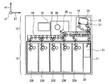
- FIG. 1 shows an external configuration of an automatic teller machine 1 according to the first embodiment.
- the automatic teller machine 1 has a substantially box-shaped housing (hereinafter also referred to as a cashier housing) 2 in which the upper corner of the front surface 2A is cut obliquely.
- a substantially box-shaped housing hereinafter also referred to as a cashier housing 2 in which the upper corner of the front surface 2A is cut obliquely.
- the direction above the automatic teller machine 1 indicated by the arrow a1 in the figure when the automatic teller machine 1 is viewed from the front surface 2A of the teller machine housing 2 is also referred to as the upward direction of the teller machine.
- the direction opposite to this is also referred to as the depositing machine downward direction, and when it is not necessary to distinguish between them, they are collectively referred to as the depositing machine vertical direction.
- the direction in front of the automatic teller machine 1 indicated by the arrow b1 in the figure when the automatic teller machine 1 is viewed facing the front surface 2A of the teller machine housing 2 is the forward direction of the teller machine.
- the direction opposite to this is also referred to as the backward direction of the deposit machine, and when it is not necessary to distinguish between these directions, they are collectively referred to as the longitudinal direction of the deposit machine.
- the left direction of the automatic teller machine 1 indicated by the arrow c1 in the figure when the automatic teller machine 1 is viewed from the front surface 2A of the teller machine housing 2 is referred to as the left direction of the teller machine.
- the direction opposite to this is also referred to as the right direction of the depositing machine, and when it is not particularly necessary to distinguish these, they are collectively referred to as the left and right direction of the depositing machine.
- the deposit machine housing 2 has, for example, a touch screen 3 capable of displaying various transaction procedure guidance images and touch operations on the surface, and a bill insertion slot for inserting and removing bills on the upper side of the front surface 2A. 4 and a plurality of operation keys 5 that can be pressed.
- the teller machine housing 2 has a card such as a cash card and a credit card inserted on the upper side of the front surface 2A, a card insertion / exhaust port 6 for discharging the card, a bankbook, and the bankbook or credit card.
- a passbook insertion outlet 7 for discharging the transaction statement is also provided.
- the teller machine housing 2 is provided with a card processing unit for performing predetermined processing relating to a card such as reading processing of an account number magnetically recorded on the card on the rear side of the card insertion / ejection slot 6 at the upper end portion inside. It has been.
- the deposit machine housing 2 is provided with a bankbook processing unit for printing transaction contents on a bankbook or transaction statement on the rear side of the bankbook insertion / exhaust port 7 at the upper end inside.
- the deposit machine housing 2 is provided with a control unit 10 and a bill deposit / withdrawal unit 11 to be described later at the lower end inside.
- the control unit 10 includes, for example, a main control unit such as a CPU (Central Processing Unit), a ROM (Read Only Memory), a RAM (Random Access Memory), and the like. Then, the main control unit reads out various programs such as basic programs and various application programs stored in advance in the ROM and expands them appropriately, thereby controlling the entire automatic teller machine 1 according to these various programs, The banknote depositing / withdrawing unit 11 and the banknote depositing / dispensing process are executed.
- a main control unit such as a CPU (Central Processing Unit), a ROM (Read Only Memory), a RAM (Random Access Memory), and the like.
- the main control unit reads out various programs such as basic programs and various application programs stored in advance in the ROM and expands them appropriately, thereby controlling the entire automatic teller machine 1 according to these various programs,
- the main control unit displays a transaction procedure guide image on the touch screen 3, and appropriately switches the transaction procedure guide image displayed on the touch screen 3 according to a touch operation on the surface of the touch screen 3 by the customer. Then, the main control unit switches a transaction procedure guide image displayed on the touch screen 3 to display a desired transaction procedure such as depositing banknotes and dispensing banknotes to the customer. invite.
- the main control unit causes a customer who follows the guidance of the transaction procedure to insert a banknote for depositing into the banknote insertion / extraction port 4.
- the main control unit causes the customer who follows the guidance of the transaction procedure to take out the banknote for withdrawal from the banknote insertion / extraction port 4.
- the main control unit discharges the card from the card insertion / extraction port 6, discharges the passbook (or transaction statement) from the passbook insertion / extraction port 7, and discharges the card and the passbook to the customer who follows the guidance of the transaction procedure. (Or transaction statement) is received.
- the main control unit can perform transactions such as deposit and withdrawal of banknotes desired by the customer in the automatic teller machine 1.
- the banknote deposit / withdrawal unit 11 includes a banknote processing block 12 and a safe block 13 that are positioned so as to overlap each other. And the banknote processing block 12 and the safe block 13 are provided with respect to the deposit machine housing
- the safe block 13 has a safe housing 20 formed in a strong box shape by a relatively thick metal plate. Further, in the safe housing 20 of the safe block 13, a single reject box 21 and a plurality of banknotes are stored in denominations in the rear direction of the deposit machine (that is, only banknotes of a specific denomination are stored). A plurality of (for example, five) banknote storages 22A to 22E are detachably mounted in order.
- a deposit / withdrawal transport unit 27 is disposed below the banknote storage case 25.
- the banknotes are transferred from the banknote storage case 25 to the lower side of the banknote storage case 25 by transport path forming components such as a transport guide, a transport roller, and a transport direction switching blade included in the deposit / withdrawal transport unit 27.
- a deposit / withdrawal transport path is formed in which the sheets are fed one by one and delivered to the transport unit 19, and banknotes are received from the transport unit 19 and stored in the banknote storage case 25.
- the temporary storage unit 18 is arranged at the center of the banknote processing block 12.
- the temporary storage unit 18 is provided with a bill temporary holding portion formed by components such as a cylindrical drum 28 and a tape reel according to the tape escrow method.
- the banknote temporary holding unit is configured to wind and hold a banknote around the peripheral side surface of the drum 28 together with the tape, and to take out the banknote by peeling the tape from the peripheral side surface of the drum 28.
- a temporary holding conveyance unit 29 is disposed below the banknote temporary holding unit.
- the banknotes taken out from between the drum 28 and the tape are transported to the lower side of the temporary banknote holding section by transport path forming parts such as transport guides and transport rollers of the temporary storage section 29.
- a temporary holding conveyance path is formed which is delivered to the unit 19 and receives bills from the conveyance unit 19 and takes in between the drum 28 and the tape.
- the transport unit 19 is connected to the banknote processing block at the lower end of the banknote processing block 12 (that is, below the depositing / withdrawing unit 16 and the temporary storage unit 18) that is substantially the center of the banknote depositing / dispensing unit 11 in the vertical direction of the depositing machine. 12 are arranged from the front end portion to the rear end portion.
- the transport unit 19 includes a transport path forming component such as a transport guide, a transport roller, and a transport direction switching blade.
- the transport unit 19 includes a substantially straight transport path that is long in the front-rear direction of the depositor, and a plurality of transport paths that branch from the transport path. , Forming.
- the transport unit 19 has a plurality of two motors arranged on the front side of the temporary holding unit 18 by a single motor located on the front side (hereinafter also referred to as a front motor).
- the transport roller is driven.
- the transport unit 19 is provided with a plurality of motors arranged on the rear side from directly below the temporary storage unit 18 by one motor located on the rear side of these two motors (hereinafter also referred to as a rear motor).
- the transport roller is driven.
- a front portion having a plurality of transport rollers driven by a front motor on the transport path formed by the transport unit 19 in front of the vicinity of the temporary storage unit 18 is also referred to as a front transport path.
- a rear portion having a plurality of conveyance rollers driven by a rear motor on the rear side of the vicinity just below 18 is also referred to as a rear conveyance path.
- the banknote processing control unit 15 selects the deposit as a desired transaction through the touch screen 3 (FIG. 1) by the customer, for example, the banknote processing control unit 15 executes the deposit process.
- the banknote processing control unit 15 opens the shutter 26 in the deposit / withdrawal unit 16 to allow the customer to insert the banknote into the banknote storage case 25.
- the banknote processing control unit 15 closes the shutter 26 in the deposit / withdrawal unit 16 and instructs the banknotes in the banknote storage case 25 when the customer instructs the banknote to be started via the touch screen 3, for example. Are taken into the transport path of the transport unit 19 one by one.
- the banknote process control part 15 discriminate
- the banknote processing control unit 15 may be a banknote that can be reused for future withdrawal processing with respect to new banknotes that are identified as normal and those that have a relatively small degree of damage. Determination is made and the final transport destination of the banknote is determined to be one of the banknote storages 22A to 22E corresponding to the denomination.
- the banknote process control part 15 judges that it is a reject banknote which is not reused for future payment processing about the banknote with a comparatively large degree of damage among the banknotes identified as normal, and the said rejection
- the final banknote transport destination is determined as the reject box 21.
- the banknote processing control unit 15 determines that banknotes that could not be identified as normal by the discrimination unit 17 are to be returned to the customer, and determines the final transport destination as the deposit / withdrawal unit 16.
- the banknote process control part 15 conveys and hold
- the banknote process control part 15 conveys to the back conveyance path via the front conveyance path in the conveyance unit 19 about the banknote (namely, banknote returned to a customer) identified as abnormal by the identification unit 17, and the said Store in the rear conveyance path. In this way, the banknote processing control unit 15 takes in and distinguishes all banknotes in the banknote storage case 25 from the deposit / withdrawal unit 16.
- the banknote process control part 15 when the banknote process control part 15 has finished discriminating all the banknotes in the banknote storage case 25, if the banknote returned to a customer is stored in a back conveyance path, the said banknote will be made to the front from a back conveyance path. It is conveyed to the deposit / withdrawal unit 16 via the conveyance path and accommodated in the bill storage case 25. Thereby, the banknote process control part 15 opens the shutter 26 in the deposit / withdrawal unit 16, returns a banknote to a customer via the banknote storage case 25, and makes the banknote storage case 25 re-insert a banknote as needed.
- the banknote processing control unit 15 has finished identifying all the banknotes in the banknote storage case 25, when banknotes to be returned to the customer are not stored in the rear conveyance path, The deposit amount is calculated based on the result of counting the denominations and the number of bills taken. And the banknote process control part 15 makes a customer select whether to continue the money_receiving
- the banknote processing control unit 15 sequentially feeds out all banknotes held from the temporary holding unit 18 and sends them to the depositing / dispensing unit 16 via the previous conveyance path. It is conveyed and stored in the banknote storage case 25. Thereby, the banknote process control part 15 opens the shutter 26 in the deposit / withdrawal unit 16, and returns a banknote to the customer via the banknote storage case 25.
- the banknote processing control unit 15 sequentially feeds out all banknotes held from the temporary holding unit 18. And the banknote process control part 15 respond
- the banknote processing control unit 15 classifies reusable banknotes among banknotes requested to be deposited by the customer, stores them in the banknote storage boxes 22A to 22E, and does not reuse them. Reject banknotes are stored in the reject box 21.
- the banknote process control part 15 can perform the deposit process of a banknote in the banknote depositing / withdrawing part 11, and can deposit the banknote as a transaction which a customer desires.
- the banknote processing control unit 15 selects withdrawal as a desired transaction via the touch screen 3 by the customer, for example, the banknote processing control unit 15 executes the withdrawal process. At this time, the banknote processing control unit 15 causes the customer to specify the withdrawal amount via the touch screen 3, and determines the denomination and the number of banknotes to be dispensed according to the designated withdrawal amount. Thereby, the banknote processing control unit 15 sequentially draws out the banknotes stored from the banknote storages 22A to 22E according to the determined denomination and number and takes them into the rear transport path of the transport unit 19.
- the banknote process control part 15 discriminate
- the banknote processing control unit 15 transports the banknote from the previous transport path to the deposit / withdrawal unit 16 and stores it in the banknote storage case 25.
- the banknote processing control part 15 will convey the said banknote from the front conveyance path to the rejection store
- the banknote process control part 15 will open the shutter 26, and will complete
- the banknote process control part 15 can perform the banknote payment process in the banknote depositing / withdrawing part 11, and can withdraw the banknote as a transaction which a customer desires.
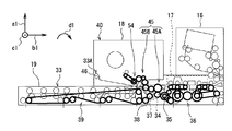
- the transport unit 19 includes, for example, a pair of left frames (hereinafter, also referred to as a left transport frame) 33 and a right frame (hereinafter, also referred to as a right transport frame) arranged to face each other.
- the plurality of types of conveyance path forming components described above are arranged between the left conveyance frame 33 and the right conveyance frame.
- the transport unit 19 is attached to the front surface of the left transport frame 33 at a predetermined position in the center in the front-rear direction of the depositing machine with the output shaft parallel to the left-right direction of the depositing machine.
- a front motor gear 35 is fixed to the output shaft of the motor 34.
- the transport unit 19 is provided with a driving force transmission part (hereinafter also referred to as a precursor power transmission part) 36 in front of the attachment position of the front motor 34.
- a plurality of types of driving force transmission parts such as a gear, a gear pulley, a pulley, and a belt arranged in an appropriate combination with the front end portion of the outer surface of the left conveyance frame 33 form a front conveyance path with the front motor gear 35.
- the precursor power transmission unit 36 is generated by causing the front motor 34 to rotate the front motor gear 35 together with the output shaft in the first rotation direction indicated by the arrow d1 in the drawing, or in the second rotation direction opposite to this.
- a driving force that is, a rotational force
- the first rotation direction which is the rotation direction of the output shaft of the front motor 34, the front motor gear 35, and the like, is the clockwise direction when the transport unit 19 is viewed from the left side
- the second rotation direction is the transport unit 19 viewed from the left side. Counterclockwise direction.
- the transport unit 19 has a plurality of front transport paths via the precursor power transmission unit 36.
- This conveyance roller can be driven so as to convey, for example, a bill from the front side to the rear side.
- the transport unit 19 rotates a plurality of front transport paths via the precursor power transmission unit 36.
- the transport roller can be driven to transport, for example, bills from the rear side to the front side.
- the transport unit 19 is mounted on the outer surface of the left transport frame 33 on the rear side of the mounting position of the front motor 34, with the rear motor 37 described above mounted with its output shaft parallel to the left-right direction of the depositing machine.
- the rear motor gear 38 is fixed to the front.
- the transport unit 19 is also provided with a driving force transmission portion (hereinafter also referred to as a rear driving force transmission portion) 39 on the rear side of the mounting position of the rear motor 37.
- the rear driving force transmission unit 39 includes a plurality of types of driving force transmission parts arranged in appropriate combination with the rear end of the outer surface of the left conveyance frame 33, and a plurality of conveyance rollers that form a rear conveyance path with the rear motor gear 38. And connected to each other. As a result, the rear driving force transmission unit 39 generates a driving force (that is, a rotational force) generated by the rear motor 37 rotating the rear motor gear 38 together with the output shaft in the first rotational direction or the second rotational direction. It can be transmitted to a plurality of conveying rollers to be formed.
- a driving force that is, a rotational force
- the transport unit 19 is connected to the rear transport path via the rear driving force transmission unit 39.
- the plurality of transport rollers can be driven to transport, for example, bills from the rear side to the front side.
- the transport unit 19 rotates the plurality of rear transport paths via the rear driving force transmission unit 39.
- This conveyance roller can be driven so as to convey, for example, bills from the front side to the rear side.
- the temporary holding unit 18 includes, for example, a pair of left frames (hereinafter also referred to as a left temporary holding frame) 40 and a right frame (hereinafter also referred to as a right temporary holding frame) arranged opposite to each other. have. Further, in the temporary storage unit 18, the component parts of the banknote temporary holding unit and the plural types of transport path forming parts of the temporary storage unit 29 are arranged between the left temporary storage frame 40 and the right temporary storage frame. .
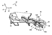
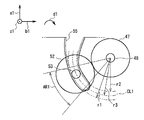
- the banknote processing block 12 is provided with a driving force transmission unit (hereinafter also referred to as an inter-unit driving force transmission unit) 45 across the transport unit 19 and the temporary storage unit 18.
- the inter-unit driving force transmission unit 45 includes a plurality of types of driving force transmission components arranged in an appropriate combination over the central portion of the outer surface of the left transport frame 33 and the lower end central portion of the outer surface of the left temporary holding frame 40.
- the motor gear 35 and a plurality of transport rollers provided in the temporary holding transport unit 29 are connected to each other. Thereby, the inter-unit driving force transmission unit 45 temporarily transfers the holding force generated by the front motor 34 rotating the front motor gear 35 together with the output shaft in the first rotation direction or the second rotation direction (that is, the rotation force). It can be transmitted to a plurality of conveying rollers provided in the section 29.
- the temporary storage unit 18 has a pair of unit support shafts 46 protruding in parallel with the left-right direction of the depositing machine, for example, at the rear lower end of the left temporary storage frame 40 and the rear lower end of the right temporary storage frame.
- the transport unit 19 has a pair of bearing portions 33 ⁇ / b> A projecting from the upper ends of the left transport frame 33 and the right transport frame at predetermined opposing positions closer to the rear than the center.
- the pair of unit support shafts 46 of the temporary storage unit 18 are rotatably inserted into the holes of the pair of bearing portions 33 ⁇ / b> A.
- the banknote processing block 12 allows the temporary storage unit 18 to move the unit support shaft 46 to the transport unit 19 so that the transport unit 19 and the temporary storage unit 18 can be maintained in a state where the banknote processing block 12 is pulled out from the deposit machine housing 2. It is attached so that it can be opened and closed by rotating in the first rotation direction and the second rotation direction around the center.
- the banknote processing block 12 opens the boundary between the front conveyance path and the rear conveyance path and the temporary retention conveyance path in a state where the temporary retention unit 18 rotates in the second rotation direction and opens upward with respect to the conveyance unit 19.
- it is attached to rotate in the first rotation direction so as to close the boundary portion between the front conveyance path and the rear conveyance path and the temporary holding conveyance path.
- the side that opens the temporary holding unit 18 (in this case, the upper side) with respect to the transport unit 19 is also referred to as the unit opening side
- the side that closes the temporary holding unit 18 with respect to the transport unit 19 (this In this case, the lower side) is also called the unit closing side.
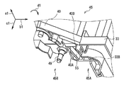
- the inter-unit driving force transmission unit 45 includes a first transmission unit 45A provided in the transport unit 19 and a second transmission unit 45B provided in the temporary storage unit 18.
- the inter-unit driving force transmission unit 45 connects the second transmission unit 45B to the first transmission unit 45A when the temporary storage unit 18 is closed with respect to the transport unit 19. Accordingly, the inter-unit driving force transmission unit 45 transmits a driving force generated by the front motor 34 to the plurality of conveyance rollers of the temporary holding conveyance unit 29 (hereinafter, this is also referred to as an inter-unit driving force transmission route). Form). Therefore, the inter-unit driving force transmission unit 45 can convey the banknotes by rotating the plurality of conveyance rollers of the temporary holding conveyance unit 29 in the first rotation direction and the second rotation direction in accordance with the operation of the front motor 34. .
- the inter-unit driving force transmission unit 45 releases the connection between the first transmission unit 45A and the second transmission unit 45B.
- the inter-unit driving force transmission unit 45 divides the inter-unit driving force transmission path in the middle, for example, manually operates the plurality of conveyance rollers of the temporary holding conveyance unit 29 for the first rotation direction and the second rotation. It can be rotated in the direction of rotation.
- the center portion of the outer surface of the left transport frame 33 is placed at a predetermined position above the mounting position of the front motor 34, for example.
- a shaft mounting hole 33B is formed.
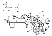
- the first transmission portion 45A is a drive gear (hereinafter, also referred to as a first joint gear) that is, for example, a spur gear for transmitting a driving force to the shaft attachment hole portion 33B of the left conveyance frame 33 to the second transmission portion 45B. 47) is attached via a first gear shaft 48 as a first shaft parallel to the left-right direction of the deposit machine.
- the first transmission portion 45A is provided in the left transport frame 33 such that the first joint gear 47 is rotatable about the first gear shaft 48 in the first rotation direction and the second rotation direction. 47 is connected to the front motor gear 35, for example, by directly meshing the teeth of each other.
- the second transmission portion 45B of the inter-unit driving force transmission portion 45 has a first gear shaft 48 when the temporary storage unit 18 is closed with respect to the transport unit 19 at the center of the lower end of the outer surface of the left temporary storage frame 40.
- a second gear shaft 49 as a second shaft is suspended in a predetermined position on the rear side in parallel with the left-right direction of the depositing machine.
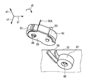
- the second transmission portion 45B has a gear support portion 50 formed in a substantially U shape by projecting a pair of support plates from both edges of the body plate.
- the gear support portion 50 has a pair of first end side shaft insertion hole portions formed at a position opposite to the first end portion of the pair of support plates, and a pair of second ends at a position opposite to the second end portion.
- a side shaft insertion hole is formed.
- the gear support 50 is, for example, a driven gear (hereinafter referred to as a spur gear) as a driving force transmission component for receiving the driving force transmitted from the first transmission portion 45A between the first ends of the pair of support plates. (This is also referred to as a second joint gear) 51 is inserted.
- the gear support portion 50 is attached to the second gear shaft 49 together with the second joint gear 51 via a pair of first end side shaft insertion hole portions and a central shaft hole of the second joint gear 51.
- the second transmission unit 45B is configured such that the second joint gear 51 and the gear support unit 50 are independent of each other around the second gear shaft 49 in the left temporary holding frame 40 in the first rotation direction and the second rotation direction. It is provided to be rotatable.
- a link gear 52 which is a spur gear, for example, is connected to the gear support portion 50 between the first ends of the pair of support plates with the second joint gear 51 meshing with and connected to each other. It is attached via a third gear shaft 53 as a third shaft inserted into the central shaft hole 52 and the pair of first end side shaft insertion holes.
- the second transmission portion 45B can rotate in the first rotation direction and the second rotation direction around the third gear shaft 53 in a state where the link gear 52 is connected to the second joint gear 51 by the gear support portion 50.
- the second gear shaft 49 is supported around the second joint gear 51 so as to be rotatable in the first rotation direction and the second rotation direction.
- the second transmission portion 45B is provided with a plurality of other types of driving force transmission components 54 (that is, other gears or other gears) shown in FIG. (Gear pulley, pulley, belt, etc.) are arranged in order.
- the second transmission unit 45 ⁇ / b> B couples these other types of driving force transmission components 54 to the second joint gear 51 and the plurality of conveyance rollers of the temporary storage unit 29.
- the second transmission unit 45B is configured such that when the temporary holding unit 18 is closed with respect to the transport unit 19 on the front side of the arrangement position of the second gear shaft 49 in the left temporary holding frame 40, the first gear shaft is left in the left transport frame 33.
- a notch 40A for fitting a front portion of the 48 arrangement position is formed.
- the gear support 50 uses the notch 40A of the left temporary holding frame 40 to connect the right end of the third gear shaft 53 to the outside of one support plate ( That is, it protrudes to the right).
- the first transmission unit 45A moves the third gear shaft 53 to connect the link gear 52 to the first joint gear 47 on the outer surface of the left transport frame 33 at the rear side of the arrangement position of the first joint gear 47.
- a guide portion 55 is provided for guiding the above.
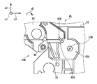
- the guide portion 55 has a guide groove that guides the movement of the third gear shaft 53 from the obliquely upper rear side to the obliquely lower rear side of the first joint gear 47, and the shaft take-in section from the center to the groove closed end is third.
- a constant groove width substantially equal to the diameter of the gear shaft 53 is formed, and the shaft entry / exit section from the center to the groove open end is formed so as to gradually widen the groove width toward the groove open end side.
- the guide portion 55 has a guide groove with a constant groove width substantially equal to the diameter of the third gear shaft 53 in the shaft take-in section that is obliquely below the rear of the first joint gear 47.
- the groove width is formed so as to be gradually wider than the diameter of the third gear shaft 53.
- the gear support unit 50 rotates in the first rotation direction around the second gear shaft 49 due to the weight of the link gear 52 or the like.
- An abutting plate 50A for restricting rotation in the direction is provided at one end of the body plate.
- a plate-like rotation restricting portion 40B is provided at a predetermined position on the upper front side of the second gear shaft 49 (that is, on the upper side of the cutout portion 40A).
- the second transmission unit 45 ⁇ / b> B is configured such that the gear support unit 50 rotates in the first rotation direction and the link gear 52 obliquely below the second joint gear 51. Is positioned, the abutment plate 50A is abutted against the rotation restricting portion 40B to restrict the rotation of the gear support portion 50 in the first rotation direction. Therefore, even if the groove width at the groove opening end of the guide groove in the guide portion 55 is relatively narrow in the guide portion 55, the second transmission portion 45B has one end portion of the third gear shaft 53 when the temporary storage unit 18 is closed with respect to the transport unit 19. Can be accurately inserted into the guide groove from the groove open end.
- the inter-unit driving force transmission unit 45 is connected to one end of the third gear shaft 53 when the temporary storage unit 18 is closed with respect to the transport unit 19. Is inserted into the guide groove from the groove opening end on the upper rear side of the first joint gear 47. Then, the inter-unit driving force transmission unit 45 is configured such that one end of the third gear shaft 53 is obliquely below the rear of the first joint gear 47 in the guide groove in accordance with the rotation of the temporary storage unit 18 in the first rotation direction.
- the link gear 52 is meshed with the first joint gear 47 and connected to the first joint gear 47 by moving to the shaft take-in section.
- the inter-unit driving force transmission unit 45 connects the first transmission unit 45A and the second transmission unit 45B via the link gear 52. That is, when the temporary storage unit 18 is closed with respect to the transport unit 19, the inter-unit driving force transmission unit 45 is connected to the first joint gear 47 that is disposed at a fixed position in the first transmission unit 45 ⁇ / b> A.
- the second joint gear 51 arranged in a fixed position is not connected directly, but the second joint gear 51 is connected via a link gear 52 provided to be displaceable in the second transmission portion 45B. Yes.
- the second transmission portion 45B the second joint gear 51, the link gear 52, and the like are attached to the gear support portion 50 formed with relatively high formation accuracy with relatively high attachment accuracy.
- the second transmission unit 45B causes the link gear 52 and the second joint gear 51 through the gear support unit 50 so that the backlash during the interlocking rotation is about 0.1 [mm], for example. Connected.
- the distance between the axes of the unit support shaft 46 and the first gear shaft 48 and the distance between the unit support shaft 46 and the third gear shaft 53 vary within the tolerance of the design value. There is a case.
- the guide portion 55 has a virtual center line CL1 passing through the inner surface of the front plate portion, the inner surface of the rear plate portion, and the center between these inner surfaces in the shaft take-in section AR1 of the guide groove. Concentric circular arcs having different first radii r1 to third radii r3 around the one gear shaft 48 are formed.
- the guide portion 55 has a groove width that is a distance between the inner surface of the front plate portion and the inner surface of the rear plate portion (that is, two types of concentric circles centered on the first gear shaft 48) in the guide groove shaft take-in section AR1.
- the difference between the first radius r1 and the second radius r2 is selected to be approximately equal to the diameter of the third gear shaft 53 as described above.
- the guide portion 55 has a distance from the first gear shaft 48 to the virtual center line CL1 (that is, a third radius r3 of a concentric circle centered on the first gear shaft 48), so that the first joint gear 47 and the link gear 52 are connected.
- the distance between the first gear shaft 48 and the third gear shaft 53 in the case of connection is selected so that the backlash during the interlocking rotation is, for example, about 0.1 [mm].
- the second transmission unit 45 ⁇ / b> B causes the above-described variation in the inter-shaft distance to be reflected on the third gear shaft 53 in the arc-shaped shaft take-in section AR ⁇ b> 1 of the guide groove. It can be replaced with variations in the stopping position of one end. Therefore, at this time, the second transmission unit 45B determines the distance between the first gear shaft 48 and the third gear shaft 53 from the first gear shaft 48 to the virtual center line CL1 regardless of the variation in the distance between the shafts. (That is, a third radius r3 of a concentric circle centered on the first gear shaft 48) can be made substantially constant.
- the second transmission unit 45B does not provide any special mechanism for manually adjusting the backlash between the first joint gear 47 and the link gear 52, for example.
- the link gear 52 can be connected to the first joint gear 47 in a state where the backlash when they rotate in conjunction with each other is optimized by a simple operation that only closes.
- the inter-unit driving force transmission unit 45 appropriately selects the arrangement position of the unit support shaft 46, the first joint gear 47, and the second joint gear 51, for example, so as to On the other hand, it can be configured. Therefore, below, the structure of the 1st form of the driving force transmission part 45 between units and the structure of a 2nd form are demonstrated in order.
- the inter-unit driving force transmission unit 45 having the configuration of the first form is also referred to as the first inter-unit driving force transmission unit 45 as appropriate, and between the units having the configuration of the second form.
- the driving force transmission unit 45 is also referred to as a second inter-unit driving force transmission unit 45, and when it is not necessary to distinguish between them, it is also simply referred to as an inter-unit driving force transmission unit 45.
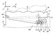
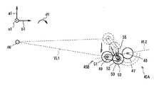
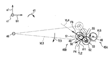
- the first inter-unit driving force transmission unit 45 is configured such that when the temporary storage unit 18 is closed with respect to the transport unit 19, the second transmission unit 45 B includes the unit support shaft 46 and the first gear shaft.
- the second gear shaft 49 and the third gear shaft 53 are arranged side by side on a first imaginary straight line VL1 that passes through a predetermined position below 48. That is, when the temporary storage unit 18 is closed with respect to the transport unit 19, the first inter-unit driving force transmission unit 45 moves the first gear shaft 48 and the second gear shaft 49 along the guide groove along the third gear shaft 53.
- the first gear shaft 48 is deviated from the second virtual straight line VL2 that passes therethrough, and the periphery of the first gear shaft 48 is turned to the unit closing side (that is, the diagonally lower rear side of the first gear shaft 48).
- the first inter-unit driving force transmission unit 45 sets the first inter-shaft distance from the first gear shaft 48 to the second gear shaft 49, and temporarily puts the first joint gear 47, the link gear 52 and the second joint gear 51 in a row.
- the distance from the first gear shaft 48 to the second gear shaft 49 in the case of connecting them in order is shorter than the distance. Accordingly, the first inter-unit driving force transmission unit 45 is arranged so that the first gear shaft 48, the third gear shaft 53, and the second gear shaft 49 are positioned at the three apexes of the triangle, respectively.
- the connected link gear 52 is further connected to the first joint gear 47.
- the first inter-unit driving force transmission unit 45 connects the first joint gear 47 of the first transmission unit 45A and the second joint gear 51 of the second transmission unit 45B via the link gear 52, thereby conveying the transport unit.
- a driving force transmission path from 19 to the temporary holding unit 18 is formed.
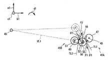
- the link gear 52 rotates in the first rotation direction. Therefore, in the first inter-unit driving force transmission unit 45, the link gear 52 is moved forward at a pressure angle ⁇ 1 of, for example, 20 degrees with respect to the tangent line TL1 of the reference pitch circle from the first joint gear 47 to the connection point of the link gear 52.
- a first pressure F1 is generated that pushes diagonally downward (that is, the unit closing side).
- the third gear shaft 53 is moved from the first joint gear 47 to the link gear 52 to the groove closing end side, which is the unit closing side, within the guide groove shaft receiving section AR1.
- a first pressure F1 is generated.
- the third gear shaft 53 is closed in the shaft take-in section AR1 of the guide groove by the first pressure F1 generated at the connection position of the link gear 52 from the first joint gear 47. Even if it moves to the side, the distance between the first gear shaft 48 and the third gear shaft 53 does not change because the shaft take-in section AR1 is arcuate as described above. Therefore, the first inter-unit driving force transmission unit 45 causes the first joint gear 47 and the link gear 52 to be connected to each other before and after the movement of the third gear shaft 53 (that is, the pitch point of each tooth and the backlash). Etc.) can be kept connected without any change.
- the second joint gear 51 rotates in the second rotation direction accordingly. Accordingly, in the first inter-unit driving force transmission unit 45, the second joint gear 51 is connected to the connection point of the second joint gear 51 from the link gear 52 at a pressure angle ⁇ 1 of, for example, 20 degrees with respect to the tangent line TL2 of the reference pitch circle. A second pressure F2 is also generated that pushes the front diagonally upward (that is, the unit opening side).
- the second joint gear 51 is connected to the link gear 52 via the gear support unit 50.
- the gear support unit 50 For this reason, in the first inter-unit driving force transmission unit 45, when the second joint gear 51 tries to move obliquely upward in the forward direction by the second pressure F2, a link is generated that causes the first pressure F1 to be pushed obliquely downward in the forward direction.
- the third gear shaft 53 of the gear 52 is pressed against the inner surface of the rear plate portion of the guide portion 55.
- the guide unit 55 and the third gear shaft 53 of the link gear 52 are It functions as a restricting part that restricts the movement, and the position of the second joint gear 51 does not change.
- the link gear 52 is connected to the first joint gear 47. It can be urged to move to the unit closing side. Accordingly, the first inter-unit driving force transmission unit 45 opens the temporary storage unit 18 with respect to the transport unit 19 even when the first joint gear 47 rotates in the second rotation direction in accordance with the operation of the front motor 34. As a result, the driving force transmission path extending from the transport unit 19 to the temporary storage unit 18 can be kept formed and unintentional splitting can be avoided.
- the first inter-unit driving force transmission unit 45 transmits the rotation of the first joint gear 47 in the second rotation direction to the second joint gear 51 via the link gear 52, and the second joint gear 51 also It can be rotated in the second rotation direction. Further, the first inter-unit driving force transmission unit 45 rotates the second joint gear 51 in the second rotation direction, and sequentially passes through a plurality of other types of driving force transmission components 54 to sequentially move the plurality of temporary holding conveyance units 29. It can be transmitted to the transport roller. Thereby, the 1st unit driving force transmission part 45 can rotate the some conveyance roller of the conveyance part 29 for temporary storage so that a banknote may be conveyed in a predetermined
- the third gear shaft 53 is moved from the first joint gear 47 to the link gear 52 to the groove opening end side that is the unit opening side in the shaft groove section AR1 of the guide groove.
- a third pressure F3 is generated.
- the second joint gear 51 rotates in the first rotation direction according to the rotation of the link gear 52 in the second rotation direction. Accordingly, in the first inter-unit driving force transmission unit 45, the second joint gear 51 is connected to the connection point of the second joint gear 51 from the link gear 52 at a pressure angle ⁇ 1 of, for example, 20 degrees with respect to the tangent line TL2 of the reference pitch circle.
- a fourth pressure F4 is also generated that pushes backward and obliquely downward (that is, the unit closing side).
- the link gear 52 is pushed while pushing the second joint gear 51 toward the unit closing side.
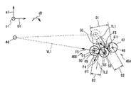
- the link gear 52 is urged so as to move from the connection position with the first joint gear 47 to the unit opening side.
- the first gear shaft 48 and the second gear shaft 49 are respectively positioned at two vertices on the triangular unit opening side protruding to the unit closing side, and the third gear shaft
- the first joint gear 47 and the second joint gear 51 are connected via a link gear 52 by positioning 53 at one vertex on the unit closing side of the triangle. Therefore, in the first inter-unit driving force transmission unit 45, the first inter-shaft distance D1 from the first gear shaft 48 to the second gear shaft 49 is the second shaft from the first gear shaft 48 to the third gear shaft 53. It is longer than the inter-distance distance D2 or the third inter-axis distance D3 from the second gear shaft 49 to the third gear shaft 53, and shorter than the distance obtained by adding the second inter-axis distance D2 and the third inter-axis distance D3.
- the gap between the first joint gear 47 and the second joint gear 51 is narrower than the gear diameter of the link gear 52. That is, the first inter-unit driving force transmission unit 45 is configured so that the link gear 52 opens the temporary storage unit 18 with respect to the transport unit 19 when the temporary storage unit 18 is closed with respect to the transport unit 19. If the gap between the first joint gear 47 and the second joint gear 51 is not widened, the first joint gear 47 and the first joint gear 47 are arranged so that they cannot move from the connection position to the unit opening side.
- the fifth pressure F5 that pushes the second joint gear 51 to the rear side acts from the link gear 52 to the second joint gear 51.
- the second joint gear 51 is fixedly disposed on the outer surface of the left temporary holding frame 40, and the unit support shaft 46 is also positioned on the left temporary holding frame 40. It is fixedly arranged.
- the second gear shaft 49 and the third gear shaft 53 are positioned on the first virtual straight line VL1 passing through the unit support shaft 46 as described above.
- the fifth pressure F5 is applied from the link gear 52 to the second joint gear 51, and the second joint gear 51 is placed on the rear side on the first virtual straight line VL1. It acts to push in the direction of 46. That is, in the first inter-unit driving force transmission unit 45, the fifth pressure F5 is applied from the link gear 52 to the second joint gear 51, and the second joint gear 51 serves as a unit support that serves as the rotation center of the temporary storage unit 18 with respect to the transport unit 19. It acts to push in the direction of the shaft 46.
- the unit support shaft 46 can receive the fifth pressure F5 by functioning as a receiving portion that receives the fifth pressure F5.
- the first unit driving force transmission unit 45 does not change the position even if the second joint gear 51 is pushed to the rear side.
- the link gear 52 is connected to the first joint gear 47. Moving from the connecting position to the unit opening side can be avoided.
- the first inter-unit driving force transmission unit 45 transmits the rotation of the first joint gear 47 in the first rotation direction to the second joint gear 51 via the link gear 52, and the second joint gear 51 also It can be rotated in the first rotation direction. Further, the first inter-unit driving force transmission unit 45 rotates the second joint gear 51 in the first rotation direction, and sequentially passes through a plurality of other types of driving force transmission components 54 to sequentially move the plurality of temporary holding conveyance units 29. It can be transmitted to the transport roller. As a result, the first inter-unit driving force transmission unit 45 causes the plurality of conveyance rollers of the temporary holding conveyance unit 29 to transfer bills in the conveyance direction opposite to the case where the first joint gear 47 rotates in the second rotation direction. It can be rotated to carry.
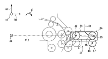
- the straight line VL4 is configured to intersect at an acute intersection angle that is as close to a parallel relationship as possible. Therefore, when the temporary storage unit 18 is closed with respect to the transport unit 19, the second inter-unit driving force transmission unit 45 moves the first gear shaft 48 and the second gear shaft 49 along the guide groove along the third gear shaft 53.
- the first gear shaft 48 is deviated from the fifth imaginary straight line VL5 that passes therethrough and turns around the first gear shaft 48 toward the unit closing side (that is, the diagonally lower rear side of the first gear shaft 48).
- the temporary storage unit 18 provided with the second transmission unit 45B which is a part of the second inter-unit driving force transmission unit 45, is provided with a temporary storage unit 29 and a bill temporary storage unit, thereby providing a certain weight.
- a temporary storage unit 29 and a bill temporary storage unit thereby providing a certain weight.
- the second inter-unit driving force transmission unit 45 As a result, in the second inter-unit driving force transmission unit 45, as in the case of the first inter-unit driving force transmission unit 45 described above, the first gear shaft 48, the third gear shaft 53, and the second gear shaft 49 are made triangular.
- the link gear 52 connected to the second joint gear 51 is further connected to the first joint gear 47 so as to be positioned at the three apexes.
- the second inter-unit driving force transmission unit 45 connects the first joint gear 47 of the first transmission unit 45A and the second joint gear 51 of the second transmission unit 45B via the link gear 52, A driving force transmission path from the transport unit 19 to the temporary storage unit 18 is formed.
- the second inter-unit driving force transmission unit 45 uses the unit closing torque TE1 to transmit the driving force while the temporary storage unit 18 is closed.
- the degree of freedom in design can be increased, such as narrowing the rotation range of the link gear 52 relative to the periphery of the second joint gear 51.
- the transport unit 19 and the temporary storage unit 18 are also provided with the above-described first inter-unit driving force transmission unit 45 at the height position of the unit support shaft 46 with respect to the lower surface of the transport unit 19, for example.
- the degree of freedom in design can be increased so as to be lower than the above.
- the second inter-unit driving force transmission unit 45 when the first joint gear 47 rotates in the second rotation direction according to the operation of the front motor 34, the same as in the case of the first inter-unit driving force transmission unit 45 described above.
- the link gear 52 can be urged to move to the unit closing side while being connected to the first joint gear 47. Accordingly, the second inter-unit driving force transmission unit 45 opens the temporary storage unit 18 with respect to the transport unit 19 even when the first joint gear 47 rotates in the second rotation direction in accordance with the operation of the front motor 34.
- the driving force transmission path extending from the transport unit 19 to the temporary storage unit 18 can be kept formed and unintentional splitting can be avoided.
- the second inter-unit driving force transmission unit 45 also rotates the first joint gear 47 in the second rotation direction by using the link gear 52 and the second joint gear 51 and other types of driving force transmission components 54.
- the data can be transmitted to a plurality of conveyance rollers of the temporary holding conveyance unit 29 sequentially.
- the second inter-unit driving force transmission unit 45 can rotate the plurality of conveyance rollers of the temporary holding conveyance unit 29 so as to convey the banknotes in a predetermined conveyance direction.
- the link gear 52 when the first joint gear 47 rotates in the first rotation direction in accordance with the operation of the front motor 34, the link gear 52 sequentially changes in accordance with the rotation.
- the second joint gear 51 rotates in the first rotation direction.
- the link gear 52 is used as a reference from the first joint gear 47 to the connection point of the link gear 52.
- a third pressure is generated that pushes backward and obliquely upward (that is, the unit opening side) with a pressure angle of, for example, 20 degrees with respect to the tangent to the pitch circle.
- the second joint gear 51 is connected to the connection point of the second joint gear 51 from the link gear 52 at this time, for example, a pressure of 20 degrees with respect to the tangent TL2 of the reference pitch circle.
- a fourth pressure F4 is also generated that pushes backward and obliquely downward (that is, the unit closing side) at the angle ⁇ 1. Therefore, in the second inter-unit driving force transmission unit 45, when the first joint gear 47 rotates in the first rotation direction in accordance with the operation of the front motor 34, the link gear while pushing the second joint gear 51 toward the unit closing side.
- the link gear 52 is urged so as to move from the connection position with the first joint gear 47 to the unit opening side by pushing the button 52 toward the unit opening side.
- the first gear shaft 48 and the second gear shaft 49 are respectively positioned at two vertices on the triangular unit opening side protruding to the unit closing side,
- the gear shaft 53 is positioned at one vertex on the unit closing side of the triangle, and the first joint gear 47 and the second joint gear 51 are connected via the link gear 52. Therefore, in the second inter-unit driving force transmission unit 45, the first inter-axis distance is longer than the second inter-axis distance and the third inter-axis distance, but is shorter than the sum of these distances. As a result, the first joint
- the gap between the gear 47 and the second joint gear 51 is narrower than the gear diameter of the link gear 52.
- the link gear 52 opens the temporary storage unit 18 with respect to the transport unit 19.
- the joint gear 47 and the second joint gear 51 are arranged so that they cannot move from the connection position with the first joint gear 47 to the unit opening side.
- the sixth pressure F6 that pushes the second joint gear 51 rearward from the link gear 52 to the second joint gear 51 with the urging to the link gear 52.
- the unit support shaft 46 is a fourth imaginary straight line passing through the second gear shaft 49 and the third gear shaft 53.
- the fourth virtual straight line VL4 intersects with the third virtual straight line VL3 and extends obliquely upward on the rear side of the unit opening side with respect to the third virtual straight line VL3.
- the sixth pressure F6 is applied from the link gear 52 to the second joint gear 51, and the second joint gear 51 is disposed on the fourth virtual straight line VL4. It works to push upward.
- the temporary storage unit 18 generates a unit closing torque TE1 that tends to rotate in the first rotation direction so as to maintain a closed state with respect to the transport unit 19 due to its own weight.
- the temporary holding unit 18 Even if the weight of the unit is relatively light and the unit closing torque TE1 is relatively small, the resultant force of the unit closing torque TE1, the fourth pressure F4, and the sixth pressure F6 causes the temporary storage unit 18 to be pushed toward the unit closing side. Force (that is, a force for rotating the temporary storage unit 18 in the first rotation direction).
- the second inter-unit driving force transmission unit 45 even if the sixth pressure F6 is applied from the link gear 52 to the second joint gear 51 so as to push upward from the position where the unit support shaft 46 is disposed, the own weight is compared.
- the light temporary holding unit 18 can function as a receiving unit that receives pressure, and the temporary holding unit 18 can receive the sixth pressure F6.
- the position of the second joint gear 51 is not changed even if the second joint gear 51 is pushed upward.
- the link gear 52 is connected to the first joint gear 47. Moving from the position to the unit opening side can also be avoided.
- the link gear 52 is kept in the connection position with the first joint gear 47, and the first joint gear 47 and the link gear 52 are in their connected state (that is, the mutual teeth).
- the connection can be continued without changing the pitch point, backlash, etc.).
- the second inter-unit driving force transmission unit 45 opens the temporary storage unit 18 with respect to the transport unit 19 even when the first joint gear 47 rotates in the first rotation direction in accordance with the operation of the front motor 34.
- the driving force transmission path extending from the transport unit 19 to the temporary storage unit 18 can be kept formed and unintentional splitting can be avoided.
- the second inter-unit driving force transmission unit 45 transmits the rotation of the first joint gear 47 in the first rotation direction to the second joint gear 51 via the link gear 52, and the second joint gear 51 also It can be rotated in the first rotation direction. Further, the second inter-unit driving force transmission unit 45 rotates the second joint gear 51 in the first rotation direction, and sequentially passes through a plurality of other types of driving force transmission components 54 to sequentially move the plurality of temporary holding conveyance units 29. It can be transmitted to the transport roller.
- the second inter-unit driving force transmission unit 45 is different in configuration from the first inter-unit driving force transmission unit 45, but the first joint gear 47 rotates in one rotation direction according to the operation of the front motor 34.
- the plurality of transport rollers of the temporary holding transport unit 29 can be rotated so as to transport bills in the transport direction opposite to that in the case where the first joint gear 47 rotates in the second rotation direction.
- FIGS. 3 and 8 illustrate the configuration of the first inter-unit driving force transmission unit 45.
- FIGS. 5A and 5B, and FIGS. 7A and 7B show the configuration of the second inter-unit driving force transmission unit 45.
- 6 and 9 show a configuration common to the first inter-unit driving force transmission unit 45 and the second inter-unit driving force transmission unit 45.
- the automatic teller machine 1 is provided with the temporary storage unit 18 with respect to the transport unit 19 so as to be openable and closable via the unit support shaft 46.
- the driving force generated by the front motor 34 provided in the transport unit 19 is transmitted to the plurality of transport rollers provided in the temporary storage unit 18 across the transport unit 19 and the temporary storage unit 18.
- An inter-unit driving force transmission unit 45 is provided.
- the second joint gear 51 and the gear support portion 50 are mutually connected to the temporary storage unit 18 as the second transmission portion 45 ⁇ / b> B of the inter-unit driving force transmission portion 45 via the second gear shaft 49.
- the gear support portion 50 is provided so as to be rotatable via a third gear shaft 53 in a state where the link gear 52 is connected to the second joint gear 51.
- the first joint gear 47 connected to the front motor gear 35 of the front motor 34 is used as the first transmission unit 45 ⁇ / b> A of the inter-unit driving force transmission unit 45 in the transport unit 19.
- a guide portion 55 that guides the link gear 52 to be connected to the first joint gear 47 by a guide groove that moves one end portion of the third gear shaft 53.
- the automatic teller machine 1 when the temporary storage unit 18 is closed with respect to the transport unit 19, the automatic teller machine 1 is configured so that the second gear gear 52 is connected to the second joint gear 51 in the inter-unit driving force transmission unit 45. While being rotated with respect to the periphery of the joint gear 51, the guide portion 55 guided to the connection position with the first joint gear 47 and connected to the first joint gear 47. Thus, the automatic teller machine 1 connects the second joint gear 51 to the first joint gear 47 via the link gear 52 in the inter-unit driving force transmission unit 45 (that is, the second transmission to the first transmission unit 45A).
- the driving force transmission path for transmitting the driving force generated by the front motor 34 from the transport unit 19 to the temporary storage unit 18 is formed.
- the automatic teller machine 1 when the first joint gear 47 rotates in the second rotation direction in accordance with the operation of the front motor 34, the automatic teller machine 1 connects the link gear 52 from the first joint gear 47. Due to the pressure generated in the direction of the pressure angle, the link gear 52 can be urged to move to the unit closing side while being connected to the first joint gear 47 by the guide portion 55. Therefore, the automatic teller machine 1 does not cause the transport unit 19 to open the temporary storage unit 18 and unintentionally divides the driving force transmission path from the transport unit 19 to the temporary storage unit 18. You can avoid that.
- the automatic teller machine 1 moves in the direction of the pressure angle from the first joint gear 47 to the connection point of the link gear 52.
- the link gear 52 is urged to move to the unit closing side by the generated pressure
- the pressure generated to move the link gear 52 from the link gear 52 to the second joint gear 51 by the urging is applied to the tip of the pressure. It can be received by the receiving portion (that is, the unit support shaft 46 or the temporary storage unit 18).
- the automatic teller machine 1 can avoid the link gear 52 from moving from the connection position with the first joint gear 47 to the unit opening side without changing the position of the second joint gear 51, As a result, it is possible to avoid unintentionally dividing the driving force transmission path extending from the transport unit 19 to the temporary storage unit 18 without causing the transport unit 19 to open the temporary storage unit 18. it can.
- the automatic teller machine 1 allows the first joint gear 47 to move according to the operation of the front motor 34 without providing a lock mechanism for locking the temporary storage unit 18 in the closed state with respect to the transport unit 19.
- the first joint gear 47 and the second joint gear 51 remain connected via the link gear 52 regardless of whether the rotation is in the first rotation direction or the second rotation direction, and the driving force transmission path is easily maintained. can do.
- the automatic teller machine 1 when the temporary storage unit 18 is closed with respect to the transport unit 19, the third gear shaft 53 is positioned closer to the unit closing side than the virtual straight line passing through the first gear shaft 48 and the second gear shaft 49. Thus, the link gear 52 is connected to the first joint gear 47.
- the automatic teller machine 1 receives the pressure generated from the link gear 52 in the second joint gear 51 at the receiving portion. Thus, the position of the second joint gear 51 is prevented from changing.
- the automatic teller machine 1 keeps the link gear 52 at the connection position with the first joint gear 47, and The one joint gear 47 and the link gear 52 can continue to be connected without changing their connection state, and the link gear 52 can be connected to the second gear according to the rotation of the first joint gear 47 in the first rotation direction. It can be accurately rotated in the direction of rotation.
- the automatic teller machine 1 when the temporary storage unit 18 is closed with respect to the transport unit 19, the second gear shaft 49 and the third gear shaft 53 are positioned on a virtual straight line passing through the unit support shaft 46, The link gear 52 is connected to the one joint gear 47. Therefore, when the first joint gear 47 rotates in the first rotation direction in accordance with the operation of the front motor 34, the automatic teller machine 1 moves from the link gear 52 to the second joint gear 51 along the virtual straight line. A pressure can be created that moves toward 46.
- the automatic teller machine 1 causes the unit support shaft 46 to function as a receiving portion without providing a receiving portion, and the pressure generated from the link gear 52 to the second joint gear 51 by the unit support shaft 46. Can be prevented from changing the position of the second joint gear 51. And since the automatic teller machine 1 does not act so that the temporary storage unit 18 may be opened with respect to the conveyance unit 19 by the said structure, it can also form the said temporary storage unit 18 so that self weight may become comparatively light. .
- the temporary holding unit 18 is formed so as to generate the unit closing torque TE1 by its own weight.
- the automatic teller machine 1 positions the second gear shaft 49 and the third gear shaft 53 on the virtual straight line passing through the unit support shaft 46. Even if the link gear 52 is not connected to the one joint gear 47, the temporary holding unit 18 is caused to function as a receiving portion, and the temporary holding unit 18 generates the second joint gear 51 from the link gear 52. It is possible to avoid a change in the position of the second joint gear 51 by receiving the pressure. Accordingly, the automatic teller machine 1 can increase the degree of freedom in designing the inter-unit driving force transmission unit 45, the temporary storage unit 18, and the transport unit 19.
- the guide groove 55 is gradually widened toward the groove opening end side in the shaft opening / closing section on the groove opening end side by the guide portion 55, and the shaft taking-in section on the groove closing end side is in the third section.
- a constant groove width substantially equal to the diameter of the gear shaft 53 is formed in an arc shape centering on the first gear shaft 48. Accordingly, in the automatic teller machine 1, the distance between the unit support shaft 46 and the first gear shaft 48 and the distance between the unit support shaft 46 and the third gear shaft 53 are within the tolerances of the design values in the second transmission unit 45B.
- the automatic teller machine 1 sets the distance between the first gear shaft 48 and the third gear shaft 53 substantially constant to the first joint gear 47 regardless of variations in the distance between the axes of the second transmission portion 45B.
- a link gear 52 can be connected.
- the first unit gear 47 and the guide unit 55 are provided in the transport unit 19 in the inter-unit driving force transmission unit 45, and the second joint gear 51 and the second joint are provided in the temporary storage unit 18.
- the case where the link gear 52 connected to the gear 51 via the gear support 50 is provided has been described.
- the present disclosure is not limited to this.
- the first joint gear 47 is provided on the transport unit 19 via the first gear shaft 48 in the inter-unit driving force transmission unit 60.
- a guide portion 61 is provided from the rear oblique upper side to the front oblique upper side of the joint gear 47.
- the guide portion 61 guides the guide groove, and the shaft entry / exit section from the center that is almost directly above the first joint gear 47 to the groove opening end on the rear obliquely upper side gradually widens the groove width.
- the shaft take-in section up to the obliquely upper groove closed end is formed in an arc shape centered on the first gear shaft 48 with a constant groove width.
- a pulley 63 as a driving force transmission component and a gear support 64 are arranged independently of each other in the first rotation direction and the second rotation centering on the pulley shaft 62 as the second shaft.
- a link gear 66 which is a gear pulley, can be rotated in the first rotation direction and the second rotation direction around the fourth gear shaft 65 as the third shaft.
- the link gear 66 and the pulley 63 are connected via an endless belt 67.
- the first joint gear 47 when the first joint gear 47 rotates in the first rotation direction according to the operation of the front motor 34, the first joint gear 47 changes to the link gear 66 within the shaft groove section of the guide groove. A pressure is generated to move the four-gear shaft 65 toward the groove closing end which is the unit closing side. That is, in the present disclosure, the link gear 66 connected to the pulley 63 via the belt 67 can be urged to move to the unit closing side while being connected to the first joint gear 47. As a result, the present disclosure does not cause the transport unit 19 to open the temporary storage unit 18 and unintentionally divides the driving force transmission path from the transport unit 19 to the temporary storage unit 18. It can be avoided.
- the fourth joint gear 47 moves from the first joint gear 47 to the link gear 66 within the guide groove shaft take-in section.
- a pressure is generated to move the gear shaft 65 toward the groove closed end.
- pressure is generated from the link gear 66 to the pulley 63 so as to push the pulley 63 rearward.
- the pulley shaft 62 and the fourth gear shaft 65 are located on the sixth virtual straight line VL6 passing through the unit support shaft 46, the rear side on the sixth virtual straight line VL6 from the link gear 66 to the pulley 63 is provided.
- the pressure can be generated so as to push in the direction of the unit support shaft 46, and the pressure can be received by the unit support shaft 46. Thereby, this indication can avoid moving link gear 66 from the connection position with the 1st joint gear 47 to the unit opening side, without changing the position of pulley 63, and, as a result, conveyance unit 19
- the drive force transmission path from the transport unit 19 to the temporary storage unit 18 can be prevented from being unintentionally divided without acting to open the temporary storage unit 18.
- the same effect as that of the above-described embodiment can be obtained even by the above configuration.
- the temporary storage unit 18 when the temporary storage unit 18 can generate a predetermined unit closing torque by its own weight, when the temporary storage unit 18 is closed with respect to the transport unit 19, the pulley shaft 62 and the Even if the link gear 66 is connected to the first joint gear 47 so that the virtual straight line passing through the four-gear shaft 65 is inclined, the same effect as in the case of the above-described embodiment can be obtained.
- the transport unit 19 is provided with the first transmission unit 45A of the inter-unit driving force transmission unit 45 together with the front motor 34, and the second transmission of the inter-unit driving force transmission unit 45 is provided to the temporary storage unit 18.
- the part 45B is provided has been described.
- the temporary holding unit 18 is provided with the first transmission unit 45A of the inter-unit driving force transmission unit 45 together with the front motor 34, and the second unit of the inter-unit driving force transmission unit 45 is provided in the transport unit 19.
- a transmission unit 45B may be provided.
- the above configuration may be applied to the various configurations described in the other embodiment 2 or the other embodiment 3.
- the present disclosure is not limited to this, and the transport unit 19 and the deposit / withdrawal unit 16 that can be opened and closed, the transport unit 19 and the discrimination unit 17 that can be opened and closed, the first unit and the second unit that can be opened and closed by the front opening, and the rear opening
- the first unit and the second unit that can be opened and closed in various configurations, such as the first unit and the second unit that can be opened and closed by the first, the first unit and the second unit that can be opened and closed by the lower opening, are widely applied. be able to.
- the gear support portion provided in the second unit so as to be rotatable about the second axis and independently of the driving force transmission portion is used as the gear support portion described above with reference to FIGS.
- the case where the U-shaped gear support 50 is applied has been described.
- the present disclosure is not limited to this, and various other types of gear support portions such as a substantially strip-shaped gear support portion and a substantially L-shaped gear support portion can be widely applied.
- Embodiment 12 a guide provided in the first unit and guiding the link gear to be connected to the drive gear by the guide groove that moves the third shaft when the first unit and the second unit are closed.
- the guide parts 55 and 61 described above with reference to FIGS. 1 to 14 are applied has been described.
- the present disclosure is not limited to this, and various other configurations of the guide portion can be widely applied, such as a guide portion in which the shaft receiving section of the guide groove is formed in a bow shape with a constant groove width.
- the unit support shaft 46 provided in the temporary storage unit 18 described above with reference to FIGS. 1 to 14 is applied as the unit support shaft that supports the first unit and the second unit so as to be openable and closable. Said about the case.
- the present disclosure is not limited to this, and a unit support shaft provided in the transport unit 19 can be applied.
- the present disclosure relates to an automatic teller machine, an automatic teller machine, a change machine, a ticket vending machine, a checkout machine, a copier, a copier, a postcard handling device, and a medium processing device, and a driving force transmission device provided in the medium processing device.
Landscapes
- Engineering & Computer Science (AREA)
- General Engineering & Computer Science (AREA)
- Mechanical Engineering (AREA)
- Delivering By Means Of Belts And Rollers (AREA)
- Gear Transmission (AREA)
Applications Claiming Priority (2)
| Application Number | Priority Date | Filing Date | Title |
|---|---|---|---|
| JP2015-111497 | 2015-06-01 | ||
| JP2015111497A JP6565343B2 (ja) | 2015-06-01 | 2015-06-01 | 駆動力伝達装置及び媒体処理装置 |
Publications (1)
| Publication Number | Publication Date |
|---|---|
| WO2016194534A1 true WO2016194534A1 (ja) | 2016-12-08 |
Family
ID=57440426
Family Applications (1)
| Application Number | Title | Priority Date | Filing Date |
|---|---|---|---|
| PCT/JP2016/063457 Ceased WO2016194534A1 (ja) | 2015-06-01 | 2016-04-28 | 駆動力伝達装置及び媒体処理装置 |
Country Status (2)
| Country | Link |
|---|---|
| JP (1) | JP6565343B2 (enExample) |
| WO (1) | WO2016194534A1 (enExample) |
Cited By (3)
| Publication number | Priority date | Publication date | Assignee | Title |
|---|---|---|---|---|
| CN106997636A (zh) * | 2017-04-18 | 2017-08-01 | 山东大学 | 回转式纸币自动分拣装置 |
| CN107025722A (zh) * | 2017-04-18 | 2017-08-08 | 山东大学 | 纸币回转接钞装置 |
| CN111739214A (zh) * | 2020-07-20 | 2020-10-02 | 恒银金融科技股份有限公司 | 一种纸币传输通道动力切换装置 |
Families Citing this family (1)
| Publication number | Priority date | Publication date | Assignee | Title |
|---|---|---|---|---|
| KR102882081B1 (ko) * | 2020-12-31 | 2025-11-05 | 효성티앤에스 주식회사 | 지폐 일시저장 모듈 |
Citations (4)
| Publication number | Priority date | Publication date | Assignee | Title |
|---|---|---|---|---|
| JPS62186155U (enExample) * | 1986-05-16 | 1987-11-26 | ||
| JPH07199571A (ja) * | 1993-12-28 | 1995-08-04 | Ricoh Co Ltd | ユニット間の駆動伝達装置 |
| JP2001125329A (ja) * | 1999-10-26 | 2001-05-11 | Ricoh Co Ltd | 画像形成装置 |
| JP2006117426A (ja) * | 2004-10-25 | 2006-05-11 | Ricoh Co Ltd | 駆動伝達機構及び画像形成装置 |
-
2015
- 2015-06-01 JP JP2015111497A patent/JP6565343B2/ja active Active
-
2016
- 2016-04-28 WO PCT/JP2016/063457 patent/WO2016194534A1/ja not_active Ceased
Patent Citations (4)
| Publication number | Priority date | Publication date | Assignee | Title |
|---|---|---|---|---|
| JPS62186155U (enExample) * | 1986-05-16 | 1987-11-26 | ||
| JPH07199571A (ja) * | 1993-12-28 | 1995-08-04 | Ricoh Co Ltd | ユニット間の駆動伝達装置 |
| JP2001125329A (ja) * | 1999-10-26 | 2001-05-11 | Ricoh Co Ltd | 画像形成装置 |
| JP2006117426A (ja) * | 2004-10-25 | 2006-05-11 | Ricoh Co Ltd | 駆動伝達機構及び画像形成装置 |
Cited By (5)
| Publication number | Priority date | Publication date | Assignee | Title |
|---|---|---|---|---|
| CN106997636A (zh) * | 2017-04-18 | 2017-08-01 | 山东大学 | 回转式纸币自动分拣装置 |
| CN107025722A (zh) * | 2017-04-18 | 2017-08-08 | 山东大学 | 纸币回转接钞装置 |
| CN107025722B (zh) * | 2017-04-18 | 2019-03-19 | 山东大学 | 纸币回转接钞装置 |
| CN111739214A (zh) * | 2020-07-20 | 2020-10-02 | 恒银金融科技股份有限公司 | 一种纸币传输通道动力切换装置 |
| CN111739214B (zh) * | 2020-07-20 | 2020-11-17 | 恒银金融科技股份有限公司 | 一种纸币传输通道动力切换装置 |
Also Published As
| Publication number | Publication date |
|---|---|
| JP2016223555A (ja) | 2016-12-28 |
| JP6565343B2 (ja) | 2019-08-28 |
Similar Documents
| Publication | Publication Date | Title |
|---|---|---|
| JP5724717B2 (ja) | 媒体処理装置及び媒体取引装置 | |
| CN103650008B (zh) | 介质处理装置 | |
| US8702088B2 (en) | Automatic transaction apparatus | |
| JP5704027B2 (ja) | 媒体処理装置及び媒体取引装置 | |
| JP5724652B2 (ja) | 媒体処理装置 | |
| JP5831321B2 (ja) | 媒体収納繰出装置及び媒体取引装置 | |
| CN105900155A (zh) | 介质处理装置和介质交易装置 | |
| US11535477B2 (en) | Medium processing device and automatic transaction device | |
| JP6565343B2 (ja) | 駆動力伝達装置及び媒体処理装置 | |
| WO2015005042A1 (ja) | 紙幣取扱装置 | |
| CN104854629A (zh) | 介质处理装置和介质交易装置 | |
| WO2014034246A1 (ja) | 紙葉類取扱装置及び紙葉類収納庫 | |
| JP7647370B2 (ja) | 媒体処理装置及び媒体取引装置 | |
| JP6237911B2 (ja) | 媒体搬送識別装置及び媒体取引装置 | |
| US10604364B2 (en) | Medium processing device and medium transaction device | |
| JP5532063B2 (ja) | 紙葉類搬送装置及び紙葉類取扱装置 | |
| CN106660732A (zh) | 介质蓄积装置和介质交易装置 | |
| JP5927909B2 (ja) | 紙葉類搬送装置及び紙葉類取扱装置 | |
| KR20160074596A (ko) | 지폐 처리 장치 | |
| JP2019066962A (ja) | 媒体収納庫及び自動取引装置 | |
| JP2018032265A (ja) | 媒体処理装置及び媒体取引装置 | |
| CN106204954A (zh) | 动力传递机构 | |
| WO2016132611A1 (ja) | 媒体取引装置 | |
| WO2021033409A1 (ja) | 媒体取引装置 | |
| JP2006209717A (ja) | 紙幣処理装置 |
Legal Events
| Date | Code | Title | Description |
|---|---|---|---|
| 121 | Ep: the epo has been informed by wipo that ep was designated in this application |
Ref document number: 16802971 Country of ref document: EP Kind code of ref document: A1 |
|
| NENP | Non-entry into the national phase |
Ref country code: DE |
|
| 122 | Ep: pct application non-entry in european phase |
Ref document number: 16802971 Country of ref document: EP Kind code of ref document: A1 |