WO2016194085A1 - Dispositif de ventilation de type à échange de chaleur - Google Patents
Dispositif de ventilation de type à échange de chaleur Download PDFInfo
- Publication number
- WO2016194085A1 WO2016194085A1 PCT/JP2015/065677 JP2015065677W WO2016194085A1 WO 2016194085 A1 WO2016194085 A1 WO 2016194085A1 JP 2015065677 W JP2015065677 W JP 2015065677W WO 2016194085 A1 WO2016194085 A1 WO 2016194085A1
- Authority
- WO
- WIPO (PCT)
- Prior art keywords
- heat exchange
- air
- heat exchanger
- heat
- exhaust
- Prior art date
Links
Images


Classifications
-
- F—MECHANICAL ENGINEERING; LIGHTING; HEATING; WEAPONS; BLASTING
- F24—HEATING; RANGES; VENTILATING
- F24F—AIR-CONDITIONING; AIR-HUMIDIFICATION; VENTILATION; USE OF AIR CURRENTS FOR SCREENING
- F24F13/00—Details common to, or for air-conditioning, air-humidification, ventilation or use of air currents for screening
- F24F13/30—Arrangement or mounting of heat-exchangers
-
- F—MECHANICAL ENGINEERING; LIGHTING; HEATING; WEAPONS; BLASTING
- F24—HEATING; RANGES; VENTILATING
- F24F—AIR-CONDITIONING; AIR-HUMIDIFICATION; VENTILATION; USE OF AIR CURRENTS FOR SCREENING
- F24F7/00—Ventilation
- F24F7/04—Ventilation with ducting systems, e.g. by double walls; with natural circulation
- F24F7/06—Ventilation with ducting systems, e.g. by double walls; with natural circulation with forced air circulation, e.g. by fan positioning of a ventilator in or against a conduit
- F24F7/08—Ventilation with ducting systems, e.g. by double walls; with natural circulation with forced air circulation, e.g. by fan positioning of a ventilator in or against a conduit with separate ducts for supplied and exhausted air with provisions for reversal of the input and output systems
-
- F—MECHANICAL ENGINEERING; LIGHTING; HEATING; WEAPONS; BLASTING
- F24—HEATING; RANGES; VENTILATING
- F24F—AIR-CONDITIONING; AIR-HUMIDIFICATION; VENTILATION; USE OF AIR CURRENTS FOR SCREENING
- F24F12/00—Use of energy recovery systems in air conditioning, ventilation or screening
- F24F12/001—Use of energy recovery systems in air conditioning, ventilation or screening with heat-exchange between supplied and exhausted air
- F24F12/006—Use of energy recovery systems in air conditioning, ventilation or screening with heat-exchange between supplied and exhausted air using an air-to-air heat exchanger
-
- F—MECHANICAL ENGINEERING; LIGHTING; HEATING; WEAPONS; BLASTING
- F28—HEAT EXCHANGE IN GENERAL
- F28D—HEAT-EXCHANGE APPARATUS, NOT PROVIDED FOR IN ANOTHER SUBCLASS, IN WHICH THE HEAT-EXCHANGE MEDIA DO NOT COME INTO DIRECT CONTACT
- F28D21/00—Heat-exchange apparatus not covered by any of the groups F28D1/00 - F28D20/00
- F28D21/0001—Recuperative heat exchangers
- F28D21/0014—Recuperative heat exchangers the heat being recuperated from waste air or from vapors
-
- F—MECHANICAL ENGINEERING; LIGHTING; HEATING; WEAPONS; BLASTING
- F28—HEAT EXCHANGE IN GENERAL
- F28D—HEAT-EXCHANGE APPARATUS, NOT PROVIDED FOR IN ANOTHER SUBCLASS, IN WHICH THE HEAT-EXCHANGE MEDIA DO NOT COME INTO DIRECT CONTACT
- F28D9/00—Heat-exchange apparatus having stationary plate-like or laminated conduit assemblies for both heat-exchange media, the media being in contact with different sides of a conduit wall
- F28D9/0062—Heat-exchange apparatus having stationary plate-like or laminated conduit assemblies for both heat-exchange media, the media being in contact with different sides of a conduit wall the conduits for one heat-exchange medium being formed by spaced plates with inserted elements
-
- F—MECHANICAL ENGINEERING; LIGHTING; HEATING; WEAPONS; BLASTING
- F28—HEAT EXCHANGE IN GENERAL
- F28F—DETAILS OF HEAT-EXCHANGE AND HEAT-TRANSFER APPARATUS, OF GENERAL APPLICATION
- F28F9/00—Casings; Header boxes; Auxiliary supports for elements; Auxiliary members within casings
- F28F9/007—Auxiliary supports for elements
- F28F9/0075—Supports for plates or plate assemblies
-
- F—MECHANICAL ENGINEERING; LIGHTING; HEATING; WEAPONS; BLASTING
- F28—HEAT EXCHANGE IN GENERAL
- F28F—DETAILS OF HEAT-EXCHANGE AND HEAT-TRANSFER APPARATUS, OF GENERAL APPLICATION
- F28F2230/00—Sealing means
-
- Y—GENERAL TAGGING OF NEW TECHNOLOGICAL DEVELOPMENTS; GENERAL TAGGING OF CROSS-SECTIONAL TECHNOLOGIES SPANNING OVER SEVERAL SECTIONS OF THE IPC; TECHNICAL SUBJECTS COVERED BY FORMER USPC CROSS-REFERENCE ART COLLECTIONS [XRACs] AND DIGESTS
- Y02—TECHNOLOGIES OR APPLICATIONS FOR MITIGATION OR ADAPTATION AGAINST CLIMATE CHANGE
- Y02B—CLIMATE CHANGE MITIGATION TECHNOLOGIES RELATED TO BUILDINGS, e.g. HOUSING, HOUSE APPLIANCES OR RELATED END-USER APPLICATIONS
- Y02B30/00—Energy efficient heating, ventilation or air conditioning [HVAC]
- Y02B30/56—Heat recovery units
Definitions
- the present invention relates to a heat exchange type ventilator that performs ventilation while exchanging heat between an air supply flow and an exhaust flow.
- a main body having an air supply path and an exhaust path formed therein, and a heat exchanger provided inside the main body, the air between the air flowing through the air supply path and the air flowing through the exhaust path are provided.
- a heat exchange type ventilator that ventilates while exchanging heat is used.
- the heat exchanger used in the heat exchange type ventilation device includes a heat exchange element in which a plurality of heat exchange plates, which are sheet-like partition plates, are stacked at intervals. Since the heat exchange plate has a rectangular shape, the heat exchange element has a rectangular parallelepiped shape.
- Patent Document 1 discloses a configuration including a frame material that covers a side extending along the stacking direction of the heat exchange plates among the heat exchange elements.
- the frame material of the heat exchanger and the main body are in contact.
- the contact part between the frame and the main body is the boundary part between the air supply path and the exhaust path, and in order to prevent mixing of air flowing through both paths, the contact between the frame body and the main body
- the part is required to be airtight to prevent air leakage from one path to the other path. In particular, even when the heat exchange element contracts due to secular change, a configuration that ensures airtightness is required.
- This invention is made in view of the above, Comprising: It aims at obtaining the heat exchange type
- the present invention includes an outdoor suction portion that sucks outdoor air, an air supply path that includes an indoor blowing portion that blows outdoor air, and an indoor suction portion that sucks indoor air.
- a main body having an exhaust passage provided with an outdoor outlet for discharging indoor air, an air supply fan provided in the air supply path, an exhaust fan provided in the exhaust path,
- a heat exchanger that exchanges heat between the air that flows through the air path and the air that flows through the exhaust path, and the heat exchanger has a plurality of sheet-like and polygonal partition members spaced apart from each other.
- It has a laminated heat exchange element, and a frame member that covers a side of the heat exchange element that extends along the lamination direction of the partition member, and the frame member has a surface opposite to the surface facing the heat exchange element, An outer protrusion extending along the stacking direction is formed.
- the heat exchange type ventilator according to the present invention has an effect that the airtightness between the frame body and the main body attached to the heat exchange element can be improved.
- the exploded perspective view which looked at the heat exchange type ventilator concerning Embodiment 1 from the bottom face side A top view of the heat exchange type ventilator concerning Embodiment 1 Sectional drawing which looked at the heat exchange type ventilator concerning Embodiment 1 from the side
- the perspective view of the heat exchanger in Embodiment 1 The exploded perspective view of the heat exchanger in Embodiment 1 Partial expanded sectional view which expanded the corner
- FIG. The partial expanded sectional view which expanded the corner
- FIG. The partial expanded sectional view which expanded the corner
- FIG. 1 is an exploded perspective view of the heat exchange type ventilator according to the first embodiment of the present invention as viewed from the top surface side.
- FIG. 2 is an exploded perspective view of the heat exchange type ventilator according to the first embodiment when viewed from the bottom surface side.
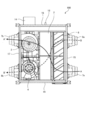
- FIG. 3 is a plan view of the heat exchange type ventilator according to the first embodiment.
- FIG. 4 is a cross-sectional view of the heat exchange type ventilator according to the first embodiment when viewed from the side.
- the heat exchange type ventilator 100 includes a casing 1, a heat exchanger 2, an air supply blower 3, an exhaust air blower 4, an air supply filter 5, and an exhaust filter 6, which are main bodies.
- the housing 1 is formed with an outdoor suction portion 7a, an indoor suction portion 8a, an indoor blowout portion 7b, and an outdoor blowout portion 8b.
- An air supply path that connects the outdoor suction portion 7a and the indoor blowing portion 7b is formed inside the housing 1.
- an exhaust path that connects the indoor suction portion 8a and the outdoor outlet portion 8b is formed inside the housing 1.
- the air supply fan 3 is provided in the air supply path.
- the air supply blower 3 generates an air supply air that causes the outdoor air (air supply) taken into the air supply path from the outdoor suction portion 7a to be blown out from the indoor side blowing portion 7b.
- the exhaust fan 4 is provided in the exhaust path.
- the exhaust blower 4 generates an exhaust flow that blows indoor air (exhaust gas) taken into the exhaust path from the indoor suction portion 8a from the outdoor blowing portion 8b.
- the heat exchanger 2 is provided at the intersection of the air supply path and the exhaust path in the housing 1 to exchange heat between the air supply airflow and the exhaust airflow.
- the heat exchange type ventilator 100 is a ventilator that performs ventilation while exchanging heat between the supply airflow and the exhaust airflow.
- the housing 1 is composed of six surfaces: an upper plate 9, a bottom plate 10 facing the upper plate 9, and four side plates 15 to 18 that block between the upper plate 9 and the bottom plate 10.
- the side plate 15 is provided with an outdoor suction portion 7a and an indoor suction portion 8a.
- the side plate 17 facing the side plate 15 is provided with an indoor side blowing portion 7b and an outdoor side blowing portion 8b.
- the path from the outdoor side suction portion 7a through the heat exchanger 2 and the air supply fan 3 becomes the air supply path AA ′
- the path from the indoor side suction portion 8a through the heat exchanger 2 and the exhaust air fan 4 Becomes the exhaust path BB ′.
- the supply blower 3 and the exhaust blower 4 are arranged on the downstream side of the heat exchanger 2 in each path.
- the control circuit 14 is attached to the side plate 18. Further, in addition to the indoor side suction portion 8a, the side plate 18 is formed with an opening 18a and an opening 18b that can be used as an air intake port to the exhaust path B-B '.
- the opening 18 a is connected upstream of the heat exchanger 2, and the air taken in from the opening 18 a is exhausted through the heat exchanger 2.
- the opening 18 b is connected downstream from the heat exchanger 2, and the air taken in from the opening 18 b is exhausted without passing through the heat exchanger 2. By exhausting without passing through the heat exchanger 2, the heat loss is not performed, but the pressure loss necessary for passing through the heat exchanger 2 can be reduced. Thereby, the load of the exhaust fan 4 can be reduced and the power consumption can be reduced.
- the side plate 16 facing the side plate 18 is formed with openings 16a and 16b which are insertion openings.
- the air supply filter 5 and the exhaust filter 6 can be inserted into the housing 1 through the openings 16a and 16b. Since both the air supply filter 5 and the exhaust filter 6 can be maintained from one side of the side plate 16, the cleaning property can be improved.
- FIG. 5 is a perspective view of the heat exchanger 2 in the first embodiment.
- FIG. 6 is an exploded perspective view of the heat exchanger 2 in the first embodiment.
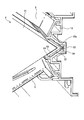
- FIG. 7 is a partial enlarged cross-sectional view in which a corner portion of the heat exchanger 2 in the first embodiment is enlarged.
- the heat exchanger 2 includes a heat exchange element 21, a frame member 22, and an end surface member 23.
- the heat exchange element 21 is formed, for example, by alternately laminating a paper partition member 21a having a sheet shape and a polygonal shape and a paper spacing member 21b having a waveform.
- a paper partition member 21a having a sheet shape and a polygonal shape
- interval holding member 21b are exhibiting rectangular shape, and the heat exchange element 21 in which these were laminated
- the stacking direction of the partition members 21a is simply referred to as the stacking direction.
- the space between the partition members 21a spaced by the spacing member 21b becomes a flow path through which air can pass.
- Total heat exchange is performed between the supply airflow and the exhaust flow through the partition member 21a by allowing the supply airflow to pass through the flow path on one side and the exhaust flow through the flow path on the other side across the partition member 21a.
- the heat exchange element 21 can exchange sensible heat or latent heat.
- the dew condensation water generated when heat exchange is performed is retained in the paper partition member 21a and the paper spacing member 21b, so that the blockage of the flow path due to icing can be reduced.
- a side extending along the stacking direction is covered with the frame member 22.
- the frame member 22 covers a side extending along the stacking direction among the sides of the heat exchange element 21. As shown in FIGS. 5 and 7, the frame member 22 has an L-shaped cross section and faces two side surfaces extending from each side of the heat exchange element 21. Outer protrusions 52 extending in the stacking direction are formed on the surface of the frame member 22 opposite to the surface facing the heat exchange element 21.
- inner projections 53 and 54 extending along the stacking direction are formed on the surface of the frame member 22 facing the heat exchange element 21.
- the inner protrusion 53 and the inner protrusion 54 are formed on the surface of the frame member 22 that faces one surface of the heat exchange element 21 with a gap in the direction perpendicular to the stacking direction. Since the frame member 22 faces the two surfaces of the heat exchange element 21, two inner protrusions 53 and two inner protrusions 54 are formed on the frame member 22.
- the inner protrusions 53 and 54 abut against the side surface of the heat exchange element 21 or bite into the side surface of the heat exchange element 21.
- the end face member 23 covers the end face of the heat exchange element 21 in the stacking direction.
- the end face member 23 is an elastic body having airtightness for preventing air leakage from the heat exchange element 21 to the end face side.
- a drain pan 11 is provided on the inner surface side of the bottom plate 10, and the drain pan 11 has a drain port 12.
- the drain pan 11 includes an air supply side drain pan 19 for retaining water when moisture contained in the air taken in from the outdoor-side suction portion 7a is condensed in the heat exchanger 2 or the like. Further, the drain pan 11 is an exhaust side drain pan in order to retain the condensed water generated when the air taken in from the indoor suction portion 8a exchanges heat with the air taken in from the outdoor suction portion 7a in the heat exchanger 2. 20.
- the exhaust side drain pan 20 communicates with the drain port 12 and can drain the drain water. In addition, when the amount of water retained in the supply side drain pan 19 is large, it is possible to provide a water channel for flowing to the drain side drain pan 20.
- the heat exchanger 2 is inserted into the housing 1 through an opening formed by removing the drain pan 11.
- the heat exchanger 2 is disposed in the housing 1 in a posture in which one side extending along the stacking direction and a side opposite to the side are aligned in the vertical direction.
- Support recesses 25 a to 25 d for supporting the heat exchanger 2 are formed inside the housing 1.
- the support recesses 25a to 25d are grooves extending along the stacking direction of the partition members 21a in the housing 1.
- FIG. 8 is a partial enlarged cross-sectional view in which the corner portion of the heat exchanger 2 accommodated in the housing 1 is enlarged in the heat exchange type ventilator 100 according to the first embodiment.
- casing 1 is expanded and shown.
- the support recess 25 a is formed in the rib frame 13 that supports the air supply filter 5 and the exhaust filter 6 in the housing 1.
- An outer protrusion 52 formed on the frame member 22 of the heat exchanger 2 is fitted into the support recess 25a. By positioning the outer projection 52 in the support recess 25a, the heat exchanger 2 is positioned in the housing 1.
- a sealing material 56 may be sandwiched between the support recess 25 a and the outer protrusion 52.
- FIG. 9 is a partial enlarged cross-sectional view in which the corner portion of the heat exchanger accommodated in the housing 1 is enlarged in the heat exchange type ventilator 100 according to the first embodiment.
- casing 1 is expanded and shown.
- the support recess 25 b is formed in the casing of the air supply fan 3 and the exhaust fan 4.
- An outer protrusion 52 formed on the frame member 22 of the heat exchanger 2 is fitted into the support recess 25b. By positioning the outer protrusion 52 in the support recess 25b, the heat exchanger 2 is positioned in the housing 1. As shown in FIG.
- a sealing material 56 may be sandwiched between the support recess 25 b and the outer protrusion 52. Further, in the case where a partition wall is provided between the air supply fan 3 and the exhaust fan 4 and the heat exchanger 2, a support recess 25b may be formed in the partition wall.
- the support recess 25 c is formed in the housing 1 on the upper plate 9 side of the heat exchanger 2, for example, the upper plate 9.
- the support recess 25 d is formed in the housing 1 on the bottom plate 10 side of the heat exchanger 2, for example, the drain pan 11.
- the outer protrusions 52 of the frame member 22 fit into the support recesses 25c and 25d.
- the sealing material 56 may be sandwiched between the support recesses 25 c and 25 d and the outer protrusion 52.
- the inner protrusions 53 and 54 formed on the frame member 22 are in line contact with the heat exchange element 21, so that the frame member 22 and the heat exchange element 21 are in surface contact. Compared to the case, the gap is less likely to occur, and the airtightness can be improved. Further, the sealing material 57 is sandwiched in the gap between the frame member 22 and the heat exchange element 21, thereby further improving the airtightness.
- the inner protrusions 53 and 54 can be used as marks for the application area when the sealing material 57 is applied.
- the inner protrusions 53 and 54 can be used as walls that prevent the sealing material 57 from leaking from the gap between the frame material 22 and the heat exchange element 21.
- the inner protrusion 54 provided on the end side of the frame member 22 relative to the inner protrusion 53 easily functions as a wall that prevents leakage of the sealing material 57.
- the inner protrusion 54 can function more reliably as a wall that prevents leakage.
- the number of the inner protrusions formed on the surface of the frame member 22 that faces one surface of the heat exchange element 21 may be one, or may be three or more.
- the sealing structure in which the outer protrusion 52 of the frame member 22 is fitted in the support recesses 25a to 25d can improve the airtightness between the heat exchanger 2 and the housing 1.
- the heat exchanger 2 contracts due to aging
- the outer protrusion 52 is fitted in the support recesses 25a to 25d, the airtightness between the heat exchanger 2 and the housing 1 is ensured. That is, even when the heat exchanger 2 contracts, airtightness is easily ensured.
- the airtightness between the heat exchanger 2 and the housing 1 is secured. Is done.
- the sealing material 56 between the outer protrusion 52 and the support recesses 25a to 25d when the heat exchanger 2 contracts, the air tightness is more reliably ensured.
- the greater the depth at which the outer protrusion 52 fits into the support recesses 25a to 25d the more airtightness can be ensured for a larger contraction amount of the heat exchanger 2.
- the heat exchanger 2 can be prevented from being displaced and dropped in the housing 1. . Further, since the heat exchanger 2 is reinforced by the frame member 22, the product life can be extended.
- the configuration described in the above embodiment shows an example of the contents of the present invention, and can be combined with another known technique, and can be combined with other configurations without departing from the gist of the present invention. It is also possible to omit or change the part.
Landscapes
- Engineering & Computer Science (AREA)
- Mechanical Engineering (AREA)
- General Engineering & Computer Science (AREA)
- Chemical & Material Sciences (AREA)
- Combustion & Propulsion (AREA)
- Physics & Mathematics (AREA)
- Thermal Sciences (AREA)
- Heat-Exchange Devices With Radiators And Conduit Assemblies (AREA)
Abstract
Dispositif de ventilation de type à échange de chaleur comprenant : un corps principal comportant un chemin d'alimentation en air et un chemin d'échappement formés dans celui-ci ; un ventilateur d'alimentation en air situé à l'intérieur du chemin d'alimentation en air ; un ventilateur d'échappement situé à l'intérieur du chemin d'échappement ; et un échangeur de chaleur (2) qui amène la chaleur à être échangée entre l'air s'écoulant le long du chemin d'alimentation en air et l'air s'écoulant le long du chemin d'échappement. L'échangeur de chaleur (2) possède : des éléments d'échange de chaleur (21) ayant une pluralité d'éléments de séparation en polygone en forme de feuille stratifiés dans ceux-ci ayant un espace entre eux ; et un matériau d'encadrement (22) recouvrant les côtés des éléments d'échange de chaleur (21) qui s'étendent le long de la direction de stratification des éléments de séparation. Le matériau d'encadrement (22) présente des saillies extérieures (52) formées dans celui-ci qui s'étendent le long de la direction de stratification, sur une surface opposée à une surface faisant face aux éléments d'échange de chaleur (21).
Priority Applications (18)
| Application Number | Priority Date | Filing Date | Title |
|---|---|---|---|
| PCT/JP2015/065677 WO2016194085A1 (fr) | 2015-05-29 | 2015-05-29 | Dispositif de ventilation de type à échange de chaleur |
| EP15894120.3A EP3306207B1 (fr) | 2015-05-29 | 2015-05-29 | Dispositif de ventilation de type à échange de chaleur |
| JP2017521348A JP6509337B2 (ja) | 2015-05-29 | 2015-05-29 | 熱交換型換気装置 |
| PCT/JP2015/080853 WO2016194257A1 (fr) | 2015-05-29 | 2015-10-30 | Dispositif de ventilation de type à échange de chaleur |
| JP2017521652A JP6671362B2 (ja) | 2015-05-29 | 2015-10-30 | 熱交換型換気装置 |
| EP15894291.2A EP3306211B1 (fr) | 2015-05-29 | 2015-10-30 | Dispositif de ventilation de type à échange de chaleur |
| JP2017521655A JP6584502B2 (ja) | 2015-05-29 | 2015-10-30 | 熱交換型換気装置 |
| JP2017521654A JP6509339B2 (ja) | 2015-05-29 | 2015-10-30 | 熱交換型換気装置 |
| JP2017521653A JP6320635B2 (ja) | 2015-05-29 | 2015-10-30 | 熱交換型換気装置 |
| EP15894293.8A EP3306213B1 (fr) | 2015-05-29 | 2015-10-30 | Dispositif de ventilation de type à échange de chaleur |
| PCT/JP2015/080855 WO2016194259A1 (fr) | 2015-05-29 | 2015-10-30 | Dispositif de ventilation de type à échange de chaleur |
| EP15894290.4A EP3306210B1 (fr) | 2015-05-29 | 2015-10-30 | Dispositif de ventilation à échange de chaleur |
| PCT/JP2015/080854 WO2016194258A1 (fr) | 2015-05-29 | 2015-10-30 | Dispositif de ventilation à échange de chaleur |
| PCT/JP2015/080857 WO2016194261A1 (fr) | 2015-05-29 | 2015-10-30 | Dispositif de ventilation de type à échange de chaleur |
| EP15894292.0A EP3306212B1 (fr) | 2015-05-29 | 2015-10-30 | Dispositif de ventilation de type à échange de chaleur |
| EP15894289.6A EP3258181B1 (fr) | 2015-05-29 | 2015-10-30 | Dispositif de ventilation de type à échange de chaleur |
| PCT/JP2015/080856 WO2016194260A1 (fr) | 2015-05-29 | 2015-10-30 | Dispositif de ventilation de type à échange de chaleur |
| JP2017521656A JP6509340B2 (ja) | 2015-05-29 | 2015-10-30 | 熱交換型換気装置 |
Applications Claiming Priority (1)
| Application Number | Priority Date | Filing Date | Title |
|---|---|---|---|
| PCT/JP2015/065677 WO2016194085A1 (fr) | 2015-05-29 | 2015-05-29 | Dispositif de ventilation de type à échange de chaleur |
Publications (1)
| Publication Number | Publication Date |
|---|---|
| WO2016194085A1 true WO2016194085A1 (fr) | 2016-12-08 |
Family
ID=57440213
Family Applications (1)
| Application Number | Title | Priority Date | Filing Date |
|---|---|---|---|
| PCT/JP2015/065677 WO2016194085A1 (fr) | 2015-05-29 | 2015-05-29 | Dispositif de ventilation de type à échange de chaleur |
Country Status (3)
| Country | Link |
|---|---|
| EP (1) | EP3306207B1 (fr) |
| JP (1) | JP6509337B2 (fr) |
| WO (1) | WO2016194085A1 (fr) |
Families Citing this family (2)
| Publication number | Priority date | Publication date | Assignee | Title |
|---|---|---|---|---|
| US11022384B2 (en) | 2018-02-19 | 2021-06-01 | Honeywell International Inc. | Framed heat exchanger core design-fabrication |
| US10837709B2 (en) | 2018-11-06 | 2020-11-17 | Honeywell International Inc. | Heat exchanger |
Citations (4)
| Publication number | Priority date | Publication date | Assignee | Title |
|---|---|---|---|---|
| JPS55141782U (fr) * | 1979-03-30 | 1980-10-09 | ||
| JPS61128587U (fr) * | 1985-01-28 | 1986-08-12 | ||
| JPH09195397A (ja) * | 1996-01-17 | 1997-07-29 | Nitto Denko Corp | 入隅シール方法及びその目地材 |
| JP2004003858A (ja) * | 2003-07-25 | 2004-01-08 | Mitsubishi Electric Corp | 換気装置 |
Family Cites Families (3)
| Publication number | Priority date | Publication date | Assignee | Title |
|---|---|---|---|---|
| JPH05223305A (ja) * | 1992-02-14 | 1993-08-31 | Toshiba Corp | 熱交換装置 |
| JPH07293960A (ja) * | 1994-04-26 | 1995-11-10 | Daikin Ind Ltd | 熱交換エレメントおよびそれを含む熱交換換気装置 |
| CN104315601A (zh) * | 2014-10-13 | 2015-01-28 | 淄博气宇空调节能设备有限公司 | 新风换气机 |
-
2015
- 2015-05-29 WO PCT/JP2015/065677 patent/WO2016194085A1/fr active Application Filing
- 2015-05-29 EP EP15894120.3A patent/EP3306207B1/fr active Active
- 2015-05-29 JP JP2017521348A patent/JP6509337B2/ja active Active
Patent Citations (4)
| Publication number | Priority date | Publication date | Assignee | Title |
|---|---|---|---|---|
| JPS55141782U (fr) * | 1979-03-30 | 1980-10-09 | ||
| JPS61128587U (fr) * | 1985-01-28 | 1986-08-12 | ||
| JPH09195397A (ja) * | 1996-01-17 | 1997-07-29 | Nitto Denko Corp | 入隅シール方法及びその目地材 |
| JP2004003858A (ja) * | 2003-07-25 | 2004-01-08 | Mitsubishi Electric Corp | 換気装置 |
Also Published As
| Publication number | Publication date |
|---|---|
| EP3306207A4 (fr) | 2019-01-16 |
| EP3306207B1 (fr) | 2020-10-21 |
| JPWO2016194085A1 (ja) | 2017-08-31 |
| EP3306207A1 (fr) | 2018-04-11 |
| JP6509337B2 (ja) | 2019-05-08 |
Similar Documents
| Publication | Publication Date | Title |
|---|---|---|
| JP6584502B2 (ja) | 熱交換型換気装置 | |
| JP6377270B2 (ja) | 熱交換型換気装置 | |
| KR20080060932A (ko) | 환기 장치의 열교환기 | |
| WO2016194085A1 (fr) | Dispositif de ventilation de type à échange de chaleur | |
| JP6509338B2 (ja) | 熱交換型換気装置 | |
| US20230221034A1 (en) | Heat exchanger and heat exchange ventilator | |
| KR101189950B1 (ko) | 환기 장치 및 환기 장치의 열교환기 | |
| WO2021095129A1 (fr) | Dispositif de ventilation du type à échange de chaleur | |
| JP2004003858A (ja) | 換気装置 | |
| JPH09217952A (ja) | 熱交換換気装置 | |
| JP2004309072A (ja) | 熱交換換気装置及び熱交換器 | |
| JP2021085596A (ja) | 筐体、熱交換装置およびそれらの製造方法 |
Legal Events
| Date | Code | Title | Description |
|---|---|---|---|
| 121 | Ep: the epo has been informed by wipo that ep was designated in this application |
Ref document number: 15894120 Country of ref document: EP Kind code of ref document: A1 |
|
| ENP | Entry into the national phase |
Ref document number: 2017521348 Country of ref document: JP Kind code of ref document: A |
|
| REEP | Request for entry into the european phase |
Ref document number: 2015894120 Country of ref document: EP |
|
| NENP | Non-entry into the national phase |
Ref country code: DE |